RU2660718C2 - Centrifugal compressor cover configured to be fastened through the output side near its input edge, containing this cover gas turbine engine - Google Patents
Centrifugal compressor cover configured to be fastened through the output side near its input edge, containing this cover gas turbine engine Download PDFInfo
- Publication number
- RU2660718C2 RU2660718C2 RU2016103716A RU2016103716A RU2660718C2 RU 2660718 C2 RU2660718 C2 RU 2660718C2 RU 2016103716 A RU2016103716 A RU 2016103716A RU 2016103716 A RU2016103716 A RU 2016103716A RU 2660718 C2 RU2660718 C2 RU 2660718C2
- Authority
- RU
- Russia
- Prior art keywords
- cover
- crankcase
- gas turbine
- turbine engine
- centrifugal compressor
- Prior art date
Links
Images
Classifications
-
- F—MECHANICAL ENGINEERING; LIGHTING; HEATING; WEAPONS; BLASTING
- F04—POSITIVE - DISPLACEMENT MACHINES FOR LIQUIDS; PUMPS FOR LIQUIDS OR ELASTIC FLUIDS
- F04D—NON-POSITIVE-DISPLACEMENT PUMPS
- F04D29/00—Details, component parts, or accessories
- F04D29/40—Casings; Connections of working fluid
- F04D29/42—Casings; Connections of working fluid for radial or helico-centrifugal pumps
- F04D29/4206—Casings; Connections of working fluid for radial or helico-centrifugal pumps especially adapted for elastic fluid pumps
-
- F—MECHANICAL ENGINEERING; LIGHTING; HEATING; WEAPONS; BLASTING
- F01—MACHINES OR ENGINES IN GENERAL; ENGINE PLANTS IN GENERAL; STEAM ENGINES
- F01D—NON-POSITIVE DISPLACEMENT MACHINES OR ENGINES, e.g. STEAM TURBINES
- F01D11/00—Preventing or minimising internal leakage of working-fluid, e.g. between stages
- F01D11/08—Preventing or minimising internal leakage of working-fluid, e.g. between stages for sealing space between rotor blade tips and stator
- F01D11/14—Adjusting or regulating tip-clearance, i.e. distance between rotor-blade tips and stator casing
-
- F—MECHANICAL ENGINEERING; LIGHTING; HEATING; WEAPONS; BLASTING
- F01—MACHINES OR ENGINES IN GENERAL; ENGINE PLANTS IN GENERAL; STEAM ENGINES
- F01D—NON-POSITIVE DISPLACEMENT MACHINES OR ENGINES, e.g. STEAM TURBINES
- F01D25/00—Component parts, details, or accessories, not provided for in, or of interest apart from, other groups
- F01D25/24—Casings; Casing parts, e.g. diaphragms, casing fastenings
- F01D25/243—Flange connections; Bolting arrangements
-
- F—MECHANICAL ENGINEERING; LIGHTING; HEATING; WEAPONS; BLASTING
- F02—COMBUSTION ENGINES; HOT-GAS OR COMBUSTION-PRODUCT ENGINE PLANTS
- F02C—GAS-TURBINE PLANTS; AIR INTAKES FOR JET-PROPULSION PLANTS; CONTROLLING FUEL SUPPLY IN AIR-BREATHING JET-PROPULSION PLANTS
- F02C6/00—Plural gas-turbine plants; Combinations of gas-turbine plants with other apparatus; Adaptations of gas- turbine plants for special use
- F02C6/04—Gas-turbine plants providing heated or pressurised working fluid for other apparatus, e.g. without mechanical power output
- F02C6/06—Gas-turbine plants providing heated or pressurised working fluid for other apparatus, e.g. without mechanical power output providing compressed gas
- F02C6/08—Gas-turbine plants providing heated or pressurised working fluid for other apparatus, e.g. without mechanical power output providing compressed gas the gas being bled from the gas-turbine compressor
-
- F—MECHANICAL ENGINEERING; LIGHTING; HEATING; WEAPONS; BLASTING
- F04—POSITIVE - DISPLACEMENT MACHINES FOR LIQUIDS; PUMPS FOR LIQUIDS OR ELASTIC FLUIDS
- F04D—NON-POSITIVE-DISPLACEMENT PUMPS
- F04D17/00—Radial-flow pumps, e.g. centrifugal pumps; Helico-centrifugal pumps
- F04D17/08—Centrifugal pumps
- F04D17/10—Centrifugal pumps for compressing or evacuating
-
- F—MECHANICAL ENGINEERING; LIGHTING; HEATING; WEAPONS; BLASTING
- F04—POSITIVE - DISPLACEMENT MACHINES FOR LIQUIDS; PUMPS FOR LIQUIDS OR ELASTIC FLUIDS
- F04D—NON-POSITIVE-DISPLACEMENT PUMPS
- F04D29/00—Details, component parts, or accessories
- F04D29/60—Mounting; Assembling; Disassembling
- F04D29/62—Mounting; Assembling; Disassembling of radial or helico-centrifugal pumps
- F04D29/624—Mounting; Assembling; Disassembling of radial or helico-centrifugal pumps especially adapted for elastic fluid pumps
-
- F—MECHANICAL ENGINEERING; LIGHTING; HEATING; WEAPONS; BLASTING
- F01—MACHINES OR ENGINES IN GENERAL; ENGINE PLANTS IN GENERAL; STEAM ENGINES
- F01D—NON-POSITIVE DISPLACEMENT MACHINES OR ENGINES, e.g. STEAM TURBINES
- F01D5/00—Blades; Blade-carrying members; Heating, heat-insulating, cooling or antivibration means on the blades or the members
- F01D5/005—Repairing methods or devices
-
- F—MECHANICAL ENGINEERING; LIGHTING; HEATING; WEAPONS; BLASTING
- F05—INDEXING SCHEMES RELATING TO ENGINES OR PUMPS IN VARIOUS SUBCLASSES OF CLASSES F01-F04
- F05D—INDEXING SCHEME FOR ASPECTS RELATING TO NON-POSITIVE-DISPLACEMENT MACHINES OR ENGINES, GAS-TURBINES OR JET-PROPULSION PLANTS
- F05D2230/00—Manufacture
- F05D2230/60—Assembly methods
Abstract
Description
Область техникиTechnical field
Настоящее изобретение относится к конструкции крышки центробежного компрессора в газотурбинном двигателе. В частности, оно относится к способу ее установки в газотурбинном двигателе для сохранения герметичности объема, предназначенного для отбираемых газов, который эта крышка образует вместе с картером газотурбинного двигателя на периферии компрессора.The present invention relates to the construction of a centrifugal compressor cover in a gas turbine engine. In particular, it relates to a method of its installation in a gas turbine engine to maintain the tightness of the volume intended for the sampled gases, which this cover forms together with the crankcase of the gas turbine engine on the periphery of the compressor.
Функцией центробежного компрессора в газотурбинном двигателе является нагнетание сжатого воздуха в камеру сгорания. Для этого ротор имеет расширяющуюся форму, захватывая воздух на выходе осевого компрессора и направляя его в радиальном направлении в канал отбора, сообщающийся с камерой сгорания. Крышка образует статор, то есть наружную стенку канала для прохождения воздуха вокруг ротора.The function of a centrifugal compressor in a gas turbine engine is to inject compressed air into the combustion chamber. To do this, the rotor has an expanding shape, capturing air at the outlet of the axial compressor and directing it in the radial direction to the selection channel in communication with the combustion chamber. The cover forms a stator, that is, the outer wall of the channel for the passage of air around the rotor.
Как известно, воздух отбирают на уровне центробежного компрессора с целью использования этого сжатого воздуха в качестве источника мощности для агрегатов газотурбинного двигателя или летательного аппарата. Отверстия, выполненные в крышке, позволяют отбирать этот воздух в канале компрессора и направлять его в систему, которая должна его распределять в использующие его агрегаты. Для обеспечения эффективного отбора необходимо, чтобы крышка была герметичной. Для этого крышка входит в герметичный контакт с деталями картера вокруг воздухозаборных отверстий, образуя объем отбора на входе системы распределения сжатого воздуха.As you know, air is taken at the level of a centrifugal compressor in order to use this compressed air as a power source for units of a gas turbine engine or aircraft. The holes made in the cover allow you to take this air in the compressor channel and direct it to the system, which should distribute it to the units using it. To ensure effective selection, the lid must be airtight. To do this, the cover comes into tight contact with the crankcase parts around the air intake openings, forming a sampling volume at the inlet of the compressed air distribution system.
Однако крышка такого компрессора является сложной в установке деталью. Действительно, она должна обеспечивать минимальный зазор с лопастями ротора для обеспечения производительности компрессора. Она должна также обеспечивать непрерывность канала на входе и на выходе. Вместе с тем, механические и термические напряжения, связанные с работой турбины, приводят к значительным деформациям всех деталей в зоне, где находится крышка, в частности, лопастей ротора.However, the cover of such a compressor is a difficult part to install. Indeed, it should provide a minimum clearance with the rotor blades to ensure compressor performance. It should also ensure continuity of the channel at the input and output. However, mechanical and thermal stresses associated with the operation of the turbine, lead to significant deformations of all parts in the area where the cover is located, in particular, the rotor blades.
Часто крышку крепят на картере при помощи кольцевого фланца, устанавливаемого на выходе на этой крышке на уровне зоны большего радиуса. Однако, как правило, воздухозаборные отверстия находятся в зоне промежуточного радиуса дальше к выходу на крышке. В этом случае болтовое крепление этого фланца на картере легко обеспечивает герметичность объема отбора на выходе воздухозаборных отверстий. Но возникает проблема обеспечения герметичности на соединении крышки с другой деталью картера, закрывающей объем отбора на входе воздухозаборных отверстий. Для достижения этого результата герметичность можно обеспечить при помощи прокладок между деталью и крышкой, как описано в документе US7824151, или за счет простой центровки, как предложено в документе ЕР2206882. Эти решения ограничивают утечки, но не обеспечивают идеальной герметичности, в частности, по причине деформаций деталей между различными режимами работы газотурбинного двигателя. Это приводит к потере давления, то есть к снижению характеристик одновременно для компрессора и для системы отбора сжатого воздуха.Often the lid is mounted on the crankcase using an annular flange mounted at the outlet of this lid at the level of a zone of a larger radius. However, as a rule, the air sampling openings are located in the intermediate radius zone further to the outlet on the lid. In this case, the bolt fastening of this flange to the crankcase easily ensures the tightness of the sampling volume at the outlet of the air intake holes. But the problem arises of ensuring tightness at the connection of the cover with another part of the crankcase, covering the selection volume at the inlet of the air intake openings. To achieve this result, tightness can be achieved by using gaskets between the part and the cover, as described in US7824151, or by simple centering, as proposed in EP2206882. These solutions limit leakages but do not provide perfect tightness, in particular due to deformation of parts between different operating modes of a gas turbine engine. This leads to a loss of pressure, that is, to a decrease in performance both for the compressor and for the compressed air extraction system.
В некоторых конструкциях крышек компрессора, описанных, например, в US2011/0002774 и FR2931521, используют фланец, располагаемый на выходе на крышке компрессора и соединяемый болтами с картером газотурбинного двигателя для крепления этой крышки. В этом случае болтовое соединение фланца позволяет обеспечить герметичность объема на входе крышки. Можно даже предусмотреть, как в FR2931521, конструкцию, закрывающую на выходе объем и окружающую крышку компрессора.Some compressor cover designs, such as those described in US2011 / 0002774 and FR2931521, for example, use a flange located at the outlet of the compressor cover and bolted to the crankcase of the gas turbine engine to secure the cover. In this case, the bolt connection of the flange allows to ensure the tightness of the volume at the inlet of the cover. You can even provide, as in FR2931521, a structure that closes the volume at the outlet and the surrounding cover of the compressor.
Однако после крепления болтами фланца на входной части крышки, в частности, для обеспечения герметичности на этом уровне, возникает проблема доступа к средствам крепления во время монтажа. Действительно, либо деталь конструкции или фланец перекрывает доступ к ним, когда крышку позиционируют для монтажа, либо, в лучшем случае, пространство, находящееся непосредственно сзади крепежных отверстий, оказывается ограниченным уже самой формой крышки. В этом случае необходимо предусмотреть конструкцию газотурбинного двигателя таким образом, чтобы иметь доступ к винтам крепления фланца крышки через выходную полость осевого компрессора, находящегося перед центробежным компрессором.However, after bolting the flange to the inlet of the cover, in particular to ensure tightness at this level, there is a problem of access to the fastening means during installation. Indeed, either a structural part or a flange blocks access to them when the cover is positioned for installation, or, in the best case, the space located directly behind the mounting holes is already limited by the shape of the cover itself. In this case, it is necessary to provide the design of the gas turbine engine in such a way as to have access to the screws that secure the cover flange through the outlet cavity of the axial compressor in front of the centrifugal compressor.
Настоящее изобретение призвано предложить простое решение для легкого крепления крышки ее входным краем при помощи стяжного средства на картере газотурбинного двигателя и с обеспечением возможности ее адаптации без существенных изменений к конструкции, когда картер газотурбинного двигателя не позволяет получить доступ к этой части крышки во время монтажа.The present invention is intended to provide a simple solution for easily securing the cover with its inlet edge using a clamping means on the crankcase of the gas turbine engine and allowing it to be adapted without significant structural changes when the crankcase of the gas turbine engine does not allow access to this part of the cover during installation.
Сущность изобретенияSUMMARY OF THE INVENTION
Объектом изобретения является крышка центробежного компрессора, предназначенная для крепления на картере газотурбинного двигателя, имеющая входной край и выходной край в направлении потока газов, проходящего через компрессор, при этом упомянутая крышка содержит множество отверстий и средств крепления. Эта крышка отличается тем, что входные средства крепления находятся на входе относительно отверстий и доступны для крепежного инструмента по меньшей мере через одно из упомянутых отверстий крышки.The object of the invention is a centrifugal compressor cover for mounting on a crankcase of a gas turbine engine, having an inlet edge and an outlet edge in the direction of the gas flow passing through the compressor, said cover comprising a plurality of holes and mounting means. This cover is characterized in that the input fastening means are at the entrance relative to the openings and are accessible to the fixing tool through at least one of the said openings of the cover.
Изобретение решает задачу облегчения монтажа крышки за счет обеспечения доступа к средствам крепления через выходную сторону, когда крышку устанавливают на место. На средствах крепления можно предварительно позиционировать стяжные средства, и в этом случае достаточно ввести крепежный инструмент через обеспечивающее к ним доступ отверстие для крепления крышки путем затягивания на картере.The invention solves the problem of facilitating the installation of the cover by providing access to the fastening means through the output side when the cover is installed in place. Coupling means can be pre-positioned on the fastening means, and in this case, it is enough to introduce the fastening tool through the opening for securing the cover to them by tightening it on the crankcase.
Предпочтительно, это расположение соответствует отверстиям, предназначенным для отбора воздуха. Таким образом, крышка изначально предусмотрена для участия в системе распределения сжатого воздуха с отбором воздуха на уровне компрессора. В этом случае, с одной стороны, обеспечивают правильное позиционирование этих отверстий и их правильный размер, чтобы не нарушать работу компрессора, и, с другой стороны, нет необходимости в изменении конструкции крышки на этом уровне.Preferably, this arrangement corresponds to the openings for air sampling. Thus, the cover was originally designed to participate in the compressed air distribution system with air sampling at the compressor level. In this case, on the one hand, they provide the correct positioning of these holes and their correct size so as not to disrupt the compressor, and, on the other hand, there is no need to change the design of the cover at this level.
Предпочтительно упомянутые входные средства крепления крышки центробежного компрессора содержат наружный фланец и крепежные отверстия, выполненные в упомянутом фланце, при этом весь узел предназначен для взаимодействия со стяжными средствами типа винта и гайки, приводимыми в действие крепежным инструментом. Отверстия в фланце можно легко выполнить путем механической обработки и легко позиционировать на фланце. Широко используемая система винта и гайки позволяют производить простое крепление крышки путем ее затягивания на картере. Например, поскольку каждое входное крепежное средство определяет ось, соответствующую вращению подвижного стяжного средства для ее крепления, существует по меньшей мере одно из упомянутых отверстий крышки, через которое проходит эта ось. В частности, в случае когда крепление производят при помощи болтов, это позволяет использовать гаечный ключ без сложного механизма.Preferably, said input means for securing the cover of the centrifugal compressor comprise an outer flange and mounting holes formed in said flange, wherein the entire assembly is designed to cooperate with coupling means such as a screw and a nut driven by a fixing tool. The holes in the flange can be easily machined and easily positioned on the flange. The widely used screw and nut system makes it easy to fasten the cover by tightening it to the crankcase. For example, since each input fixing means defines an axis corresponding to the rotation of the movable coupling means for securing it, at least one of said cover openings exists through which this axis passes. In particular, in the case where the fastening is carried out using bolts, this allows the use of a wrench without a complicated mechanism.
Предпочтительно упомянутый фланец образует стенку, полностью окружающую упомянутую крышку. Этот фланец, выполненный с возможностью обеспечения на входе упомянутых отверстий герметичного окружного соединения с деталью картера после затягивания средств крепления, препятствует выходу через переднюю сторону воздуха, проходящего через отверстия крышки, во время работы газотурбинного двигателя. Прежде всего это позволяет избежать установления сообщения между пространством, в которое попадает воздух, выходящий через отверстия крышки, с входными ступенями газотурбинного двигателя и нарушения его работы. Кроме того, устройства, описанные в вышеупомянутых документах, обеспечивают герметичность соединения крышки с картером на уровне ее наибольшего радиуса на выходе отверстий. Таким образом, во время работы газотурбинного двигателя установление сообщения потока в компрессоре с наружным пространством крышки через отверстия, используемые для введения крепежных инструментов, не влияет на производительность компрессора, поскольку давление уравновешивается. Точно также, с точки зрения отбора воздуха для использования в других агрегатах, отсутствие утечек на этом уровне позволяет сохранять высокое давление в системе распределения воздуха.Preferably, said flange forms a wall completely surrounding said cover. This flange, made with the possibility of providing at the entrance of the said openings a tight circular connection with the crankcase after tightening the fastening means, prevents the air passing through the openings of the cover through the front side during operation of the gas turbine engine. First of all, this allows avoiding the establishment of communication between the space into which air enters through the openings of the cover with the inlet stages of the gas turbine engine and disruption of its operation. In addition, the devices described in the aforementioned documents provide a tight connection between the cover and the crankcase at the level of its largest radius at the outlet of the holes. Thus, during the operation of the gas turbine engine, the establishment of a flow message in the compressor with the outer space of the lid through the holes used to introduce fixing tools does not affect the compressor performance, since the pressure is balanced. In the same way, from the point of view of air selection for use in other units, the absence of leaks at this level allows you to maintain high pressure in the air distribution system.
Предпочтительно, в каждое крепежное отверстие фланца можно вставить стяжной винт по меньшей мере через одно из упомянутых отверстий крышки. Это позволяет вводить, например, винты после установки крышки на картере. В варианте, если отверстия фланца сажают на связанные с картером шпильки, отверстия позволяют вставлять гайки и устанавливать их на шпильках.Preferably, a tightening screw can be inserted into each mounting hole of the flange through at least one of said cover openings. This allows you to insert, for example, screws after installing the cover on the crankcase. In the embodiment, if the holes of the flange are planted on the studs connected to the crankcase, the holes allow you to insert the nuts and install them on the studs.
Предпочтительно, упомянутый фланец расположен вблизи входного края крышки.Preferably, said flange is located near the inlet edge of the cover.
В частном варианте выполнения крышка центробежного компрессора дополнительно содержит выходной фланец крепления на картере газотурбинного двигателя, соединенный с наружной стенкой крышки между упомянутыми отверстиями и выходным краем и образующий уплотнительное средство. Использование фланца крепления на выходе для обеспечения герметичного окружного соединения с картером позволяет легко адаптировать крышку для обеспечения идеальной герметичности объема сбора отбираемых газов и облегчения ее установки. Предпочтительно, этот фланец крепят на картере газотурбинного двигателя при помощи болтов.In a particular embodiment, the lid of the centrifugal compressor further comprises an outlet mounting flange on the crankcase of the gas turbine engine connected to the outer wall of the lid between said openings and the outlet edge and forming sealing means. The use of a mounting flange at the outlet to ensure a tight circumferential connection with the crankcase makes it easy to adapt the cover to ensure perfect tightness of the collection volume of the sampled gases and to facilitate its installation. Preferably, this flange is bolted to the crankcase of a gas turbine engine.
Объектом изобретения является также газотурбинный двигатель, содержащий центробежный компрессор с описанной выше крышкой, картер которого выполнен с возможностью образования герметичного соединения с входным фланцем крышки после затягивания стяжных средств.The object of the invention is also a gas turbine engine containing a centrifugal compressor with the cover described above, the crankcase of which is configured to form a tight connection with the inlet flange of the cover after tightening the clamping means.
Предпочтительно, картер выполнен с возможностью образования с упомянутой крышкой по меньшей мере одного замкнутого объема для отбора воздуха, проходящего через отверстия крышки.Preferably, the crankcase is configured to form with said cover at least one closed volume for taking air passing through the openings of the cover.
Предпочтительно, по меньшей мере часть отверстий крышки и упомянутый объем отбора воздуха выполнены с возможностью участия в системе отбора воздуха.Preferably, at least a portion of the cover openings and said air take-off volume are adapted to participate in the air take-off system.
Краткое описание изобретенияSUMMARY OF THE INVENTION
Настоящее изобретение и его другие детали, отличительные признаки и преимущества будут более очевидны из нижеследующего описания со ссылками на прилагаемые чертежи, на которых:The present invention and its other details, features and advantages will be more apparent from the following description with reference to the accompanying drawings, in which:
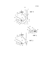
Фиг.1 - вид в осевом разрезе первого варианта выполнения компрессора газотурбинного двигателя с заявленной крышкой.Figure 1 is a view in axial section of a first embodiment of a compressor of a gas turbine engine with the claimed cover.
Фиг.2 - вид, увеличенный относительно Фиг.1, входной зоны крепления крышки с винтом и гайкой в разборе.Figure 2 is a view enlarged relative to Figure 1, the input zone of the fastening of the cover with a screw and nut in the analysis.
Фиг.3 - вид в осевом разрезе газотурбинного двигателя с крышкой, показанной на Фиг.1, в фазе монтажа.Figure 3 is a view in axial section of a gas turbine engine with the cover shown in Figure 1, in the installation phase.
Как показано на Фиг.1, заявленная крышка 1 центробежного компрессора образует радиально наружную стенку канала, в котором вращаются лопасти 2 рабочего колеса 3 ротора. Узел имеет симметрию вращения вокруг не показанной оси, которая является горизонтальной относительно Фиг.1 и находится снизу показанных на чертеже деталей. Ротор, вращаясь вокруг этой оси, всасывает воздух через свой вход 4, который ориентирован в осевом направлении и нагнетает его с более высоким давлением через свой выход 5, ориентированный в радиальном направлении. Как правило, этот компрессор направляет сжатый воздух в радиальный канал 6 отбора, предназначенный для питания камеры сгорания, которая не показана, но находится справа относительно Фиг.1, и он питается на входе от осевого компрессора 7.As shown in figure 1, the inventive cover 1 of the centrifugal compressor forms a radially outer wall of the channel in which the rotor blades 2 of the
Крышка 1 представляет собой тело вращения вокруг оси симметрии компрессора, форма которого соответствует, с учетом минимального зазора, форме поверхности, сканируемой радиальным концом лопастей 2. Кроме того, крышка 1 выполнена таким образом, чтобы ее входной передний край 8 обеспечивал непрерывность формы с радиально наружной стенкой канала осевого компрессора 7 и чтобы ее выходной задний край 10 обеспечивал непрерывность формы со стенкой 11 канала 6 отбора.The cover 1 is a body of rotation around the axis of symmetry of the compressor, the shape of which corresponds, taking into account the minimum clearance, to the shape of the surface scanned by the radial end of the blades 2. In addition, the cover 1 is made so that its input
Крепление крышки на картере газотурбинного двигателя должно позволять позиционировать ее с достаточной точностью для соблюдения вышеупомянутых требований, а также позволять крышке перемещаться в зависимости от условий работы, чтобы следовать деформациям лопастей 2 с сохранением оптимального зазора.The fastening of the cover on the crankcase of the gas turbine engine should allow it to be positioned with sufficient accuracy to comply with the above requirements, and also allow the cover to move depending on operating conditions in order to follow the deformations of the blades 2 while maintaining an optimal clearance.
Было предложено несколько решений, в частности, крепление крышки при помощи двух фланцев, как указано в вышеупомянутых документах US2011/0002774 и EP2206882. Что касается удержания крышки, этот монтаж с двумя фланцами предопределяет точки крепления крышки, что необходимо учитывать в характере осуществляемых соединений. Вместе с тем, как показывают упомянутые известные источники, такой монтаж можно вполне реализовать. Изобретение может использовать другие комбинации между фланцами, регулируя упругость обеспечиваемых ими соединений.Several solutions have been proposed, in particular, fixing the cover using two flanges, as indicated in the aforementioned documents US2011 / 0002774 and EP2206882. As for the cover holding, this mounting with two flanges determines the fixing points of the cover, which must be taken into account in the nature of the connections made. At the same time, as the mentioned well-known sources show, such an installation can be fully implemented. The invention may use other combinations between the flanges, adjusting the elasticity of the joints provided by them.
Первый вариант выполнения изобретения предусматривает использование такого крепления с двумя фланцами. Кольцевой фланец 12, присоединяемый на выходе в части максимального радиуса крышки 1 относительно оси вращения, крепят болтами по краю окружной детали 13 картера. Кроме того, крышку крепят также в ее входной части при помощи фланца 14 на другой детали 15 картера по всей ее окружности. Этот фланец 14 является деталью в виде усеченного конуса, которая расположена радиально снаружи крышки 1 и отделяет входной край 8 от выходного края 10 по всей окружности крышки. Его крепят на крышке 1 очень близко от входного края 8 крышки 1, и он имеет небольшое радиальное удлинение. Таким образом, соединение между крышкой и деталью 15 картера происходит очень близко от входного края 8. Этот фланец 14 представляет дополнительный интерес с учетом своего положения, что будет показано ниже.The first embodiment of the invention provides for the use of such a mounting with two flanges. An
В некоторых газотурбинных двигателях крышка участвует также функции отбора сжатого воздуха на уровне компрессора с целью его подачи в систему распределения в направлении различных агрегатов внутри летательного аппарата.In some gas turbine engines, the cover also involves the function of taking compressed air at the compressor level to supply it to the distribution system in the direction of the various units inside the aircraft.
В представленном примере в крышке 1 выполнено несколько отверстий 16, одно из которых показано в разрезе на Фиг.1. Эти отверстия 16 расположены на венце вокруг оси симметрии с радиусом, приблизительно соответствующим минимальному радиусу крышки по входному краю 8 и увеличенным на четверть разности с максимальным радиусом по выходному краю 10. Иначе говоря, эти отверстия находятся также в зоне максимальной кривизны осевого профиля крышки 1. Таким образом, они находятся в зоне, где крышка играет наименьшую роль для удержания потока в компрессоре. Следовательно, они могут быть выполнены с достаточным сечением, чтобы пропускать часть воздуха, циркулирующего в роторе, в направлении наружной стороны крышки, существенно не влияя при этом на работу компрессора.In the presented example,
Отбираемый воздух собирается в объеме 17 сбора, который, в свою очередь, сообщается с непоказанной системой распределения. В примере, представленном на Фиг.1, этот объем 17 ограничен вблизи крышки, часть крышки 1 вместе с:The sampled air is collected in a
- выходным фланцем 12 на выходе, затем кольцевой деталью 13 картера,- an
- входным фланцем 14 на входе, затем кольцевой деталью 15 картера.- an
Как показано на Фиг.2, входной фланец 15 закреплен на детали 15 при помощи систем, включающих в себя винт 18 и гайку 19, проходящие через отверстия 20 и 21 фланца 14 и детали 15. Разумеется, во время монтажа крышки эти отверстия располагают друг против друга. Эти отверстия, в частности, отверстия 20, выполненные в фланце 14, образуют, таким образом, вместе с окружающей их частью фланца 14 средства крепления, связанные с крышкой 1. Эти средства 20 крепления взаимодействуют с отверстиями 21, находящимися на краю кольцевой детали 15, и со средствами 18 и 19 болтового соединения для прижатия фланца 14 к детали 15. Входящие друг с другом в контакт части фланца и края детали 15 выполнены, в случае необходимости, с установленной между ними регулировочной прокладкой 23 для обеспечения герметичности соединения по отношению к сжатому воздуху, благодаря давлению со стороны средств 18-19 болтового соединения после их затягивания. Аналогично, выходной фланец 12 закреплен болтовыми средствами на краю детали 13 картера и обеспечивает герметичность объема 17 сбора отбираемого воздуха с выходной стороны крышки 1.As shown in FIG. 2, the
В целом фланец 12 расположен радиально снаружи крышки, что позволяет получить доступ к ее концу, закрепленному болтами на картере через выходную сторону этого фланца, во время операций монтажа или демонтажа крышки.In general, the
Трудность монтажа в этой конфигурации состоит в том, что для обеспечения герметичности на входе крышки деталь 15 картера расположена ближе к входному краю 8 крышки 1, где радиус является наименьшим. Во время монтажа в газотурбинном двигателе крышку устанавливают через выходную сторону уже установленных частей картера и компрессора, как показано на Фиг.3. Крышка 1, как и выходной фланец 12, перекрывает доступ к средствами 20 крепления и 18-19 болтового соединения. В заявленной крышке отверстия 16 крышки 1, предусмотренные для отбора воздуха, расположены напротив крепежных отверстий 20 в фланце 14 таким образом, чтобы крепежный инструмент, например, гаечный ключ 22, мог захватить не показанную на Фиг.3 головку винта 18, походящего через отверстия 20 фланца 14 и отверстия 21 детали 15 картера, для его завинчивания на гайке 19.The difficulty of installation in this configuration is that to ensure tightness at the inlet of the lid, the
В представленном примере гайка 19 закреплена напротив отверстия 21 детали 15 картера с входной стороны и заблокирована от вращения. Следовательно, крышку можно установить с задней стороны картера для завинчивания винтов 18 в гайки 18 через отверстия 20 фланца и отверстия 21 детали 15 картера, которые предварительно следует совместить. Кроме того, при соблюдении критерия работы компрессора это отверстие 16 является достаточно широким, чтобы через него можно было пропустить винт 18 для его введения в гайку 19 через отверстия 20 и 21, а также головку ключа 22, которая будет взаимодействовать с головкой винта 18.In the presented example, the
В варианте выполнения головка ключа 22 может быть менее широкой, чем головка винта 18, в отличие от того, что показано на Фиг.3, если она взаимодействует с вырезом в головке винта 18. Таким образом, винты 18 можно предварительно позиционировать в крепежных отверстиях 20 входного фланца 14 крышки перед ее установкой на картере. В этом случае сечение воздухозаборного отверстия 16 должно пропускать только относительно тонкий ключ.In an embodiment, the head of the key 22 may be less wide than the head of the
В другом варианте выполнения направление установки на место винтов 18 или гаек 19 меняется на противоположное. Винт 18, заблокированный от вращения на детали 15 картера, образует, таким образом, шпильку, на которую сажают отверстие 20 фланца 14, прежде чем завинтить гайку 19.In another embodiment, the installation direction of the
Claims (10)
Applications Claiming Priority (3)
| Application Number | Priority Date | Filing Date | Title |
|---|---|---|---|
| FR1357109 | 2013-07-18 | ||
| FR1357109A FR3008750B1 (en) | 2013-07-18 | 2013-07-18 | TURBOMACHINE CENTRIFUGAL COMPRESSOR COVER FIXED BY THE DOWNSTAIR NEAR ITS UPSTREAM EDGE, TURBOMACHINE HAVING THIS COVER. |
| PCT/FR2014/051842 WO2015008000A2 (en) | 2013-07-18 | 2014-07-17 | Cover of a turbomachine centrifugal compressor capable of being rigidly connected via the downstream side near to the upstream edge of same, and turbomachine comprising this cover |
Publications (3)
| Publication Number | Publication Date |
|---|---|
| RU2016103716A RU2016103716A (en) | 2017-08-23 |
| RU2016103716A3 RU2016103716A3 (en) | 2018-05-10 |
| RU2660718C2 true RU2660718C2 (en) | 2018-07-09 |
Family
ID=49620058
Family Applications (1)
| Application Number | Title | Priority Date | Filing Date |
|---|---|---|---|
| RU2016103716A RU2660718C2 (en) | 2013-07-18 | 2014-07-17 | Centrifugal compressor cover configured to be fastened through the output side near its input edge, containing this cover gas turbine engine |
Country Status (8)
| Country | Link |
|---|---|
| US (1) | US10100842B2 (en) |
| EP (1) | EP3022404B1 (en) |
| JP (1) | JP6475239B2 (en) |
| CN (1) | CN105452616B (en) |
| CA (1) | CA2919596C (en) |
| FR (1) | FR3008750B1 (en) |
| RU (1) | RU2660718C2 (en) |
| WO (1) | WO2015008000A2 (en) |
Families Citing this family (4)
| Publication number | Priority date | Publication date | Assignee | Title |
|---|---|---|---|---|
| FR3040077B1 (en) * | 2015-08-12 | 2017-08-11 | Snecma | TURBOMACHINE, SUCH AS A TURBO AIRBORNE OR TURBOPROPULSER |
| FR3103241B1 (en) | 2019-11-15 | 2021-12-17 | Safran Trans Systems | WHEEL FOR A TURBOMACHINE EPICYCLOIDAL GEAR GEAR REDUCER SATELLITE CARRIER |
| FR3103240B1 (en) | 2019-11-15 | 2022-07-15 | Safran Aircraft Engines | IMPELLER FOR A TURBOMACHINE EPICYCLOIDAL GEAR SPEED REDUCER SATELLITE CARRIER |
| FR3128753B1 (en) | 2021-11-03 | 2023-11-24 | Safran Trans Systems | MECHANICAL SPEED REDUCER FOR AN AIRCRAFT TURBOMACHINE |
Citations (4)
| Publication number | Priority date | Publication date | Assignee | Title |
|---|---|---|---|---|
| US4687412A (en) * | 1985-07-03 | 1987-08-18 | Pratt & Whitney Canada Inc. | Impeller shroud |
| EP1167722A2 (en) * | 2000-06-20 | 2002-01-02 | General Electric Company | Methods and apparatus for delivering cooling air within gas turbines |
| RU2010153329A (en) * | 2008-05-26 | 2012-07-10 | Турбомека (Fr) | GAS TURBINE ENGINE COMPRESSOR COVER CONTAINING AXIAL STOP |
| FR2976623A1 (en) * | 2011-06-20 | 2012-12-21 | Snecma | DECOUPLING DEVICE FOR DOUBLE FLOW TURBOMOTEUR |
Family Cites Families (14)
| Publication number | Priority date | Publication date | Assignee | Title |
|---|---|---|---|---|
| US4248566A (en) * | 1978-10-06 | 1981-02-03 | General Motors Corporation | Dual function compressor bleed |
| US4264271A (en) * | 1979-03-15 | 1981-04-28 | Avco Corporation | Impeller shroud of a centrifugal compressor |
| JPH03260336A (en) | 1990-03-12 | 1991-11-20 | Mitsubishi Heavy Ind Ltd | Bleed device of centrifugal compressor |
| US6183195B1 (en) * | 1999-02-04 | 2001-02-06 | Pratt & Whitney Canada Corp. | Single slot impeller bleed |
| US7094029B2 (en) * | 2003-05-06 | 2006-08-22 | General Electric Company | Methods and apparatus for controlling gas turbine engine rotor tip clearances |
| US7435050B2 (en) * | 2006-01-11 | 2008-10-14 | United Technologies Corporation | Split flange V-groove and anti-rotation mating system |
| US7824151B2 (en) * | 2006-12-06 | 2010-11-02 | United Technologies Corporation | Zero running clearance centrifugal compressor |
| US8292592B2 (en) * | 2008-04-02 | 2012-10-23 | United Technologies Corporation | Nosecone bolt access and aerodynamic leakage baffle |
| FR2930588B1 (en) * | 2008-04-24 | 2010-06-04 | Snecma | COMPRESSOR ROTOR OF A TURBOMACHINE HAVING CENTRIFIC AIR-LEVELING MEANS |
| US8087880B2 (en) * | 2008-12-03 | 2012-01-03 | General Electric Company | Active clearance control for a centrifugal compressor |
| US8147178B2 (en) | 2008-12-23 | 2012-04-03 | General Electric Company | Centrifugal compressor forward thrust and turbine cooling apparatus |
| US8616854B2 (en) * | 2009-03-05 | 2013-12-31 | Rolls-Royce Corporation | Nose cone assembly |
| US9353685B2 (en) * | 2012-12-21 | 2016-05-31 | United Technologies Corporation | Turbine engine nosecone with deformation region |
| US9650916B2 (en) * | 2014-04-09 | 2017-05-16 | Honeywell International Inc. | Turbomachine cooling systems |
-
2013
- 2013-07-18 FR FR1357109A patent/FR3008750B1/en active Active
-
2014
- 2014-07-17 EP EP14790146.6A patent/EP3022404B1/en active Active
- 2014-07-17 JP JP2016526683A patent/JP6475239B2/en active Active
- 2014-07-17 US US14/904,880 patent/US10100842B2/en active Active
- 2014-07-17 RU RU2016103716A patent/RU2660718C2/en active
- 2014-07-17 CN CN201480043939.4A patent/CN105452616B/en active Active
- 2014-07-17 CA CA2919596A patent/CA2919596C/en active Active
- 2014-07-17 WO PCT/FR2014/051842 patent/WO2015008000A2/en active Application Filing
Patent Citations (4)
| Publication number | Priority date | Publication date | Assignee | Title |
|---|---|---|---|---|
| US4687412A (en) * | 1985-07-03 | 1987-08-18 | Pratt & Whitney Canada Inc. | Impeller shroud |
| EP1167722A2 (en) * | 2000-06-20 | 2002-01-02 | General Electric Company | Methods and apparatus for delivering cooling air within gas turbines |
| RU2010153329A (en) * | 2008-05-26 | 2012-07-10 | Турбомека (Fr) | GAS TURBINE ENGINE COMPRESSOR COVER CONTAINING AXIAL STOP |
| FR2976623A1 (en) * | 2011-06-20 | 2012-12-21 | Snecma | DECOUPLING DEVICE FOR DOUBLE FLOW TURBOMOTEUR |
Also Published As
| Publication number | Publication date |
|---|---|
| CA2919596C (en) | 2020-12-15 |
| WO2015008000A3 (en) | 2015-04-09 |
| RU2016103716A3 (en) | 2018-05-10 |
| CN105452616A (en) | 2016-03-30 |
| FR3008750A1 (en) | 2015-01-23 |
| JP2016528428A (en) | 2016-09-15 |
| JP6475239B2 (en) | 2019-02-27 |
| US10100842B2 (en) | 2018-10-16 |
| RU2016103716A (en) | 2017-08-23 |
| EP3022404B1 (en) | 2017-03-08 |
| EP3022404A2 (en) | 2016-05-25 |
| CN105452616B (en) | 2017-06-09 |
| US20160195099A1 (en) | 2016-07-07 |
| CA2919596A1 (en) | 2015-01-22 |
| WO2015008000A2 (en) | 2015-01-22 |
| FR3008750B1 (en) | 2015-07-17 |
Similar Documents
| Publication | Publication Date | Title |
|---|---|---|
| RU2660718C2 (en) | Centrifugal compressor cover configured to be fastened through the output side near its input edge, containing this cover gas turbine engine | |
| EP1961936B1 (en) | Hybrid turbocharger | |
| RU2717187C2 (en) | Fixing system, which is equipped with engine wall | |
| US10598096B2 (en) | Rotor disk having a centripetal air collection device, compressor comprising said disc and turbomachine with such a compressor | |
| US20140144146A1 (en) | Tile fastening arrangement of a gas-turbine combustion chamber | |
| RU2496988C2 (en) | Gas turbine engine rotor, turbojet and plug for gas turbine engine rotor | |
| US9017029B2 (en) | Gas-turbine balancing device | |
| RU2010147837A (en) | GAS TURBINE ENGINE COMPRESSOR ROTOR CONTAINING CENTRIFUGAL AIR INTAKE MEANS | |
| GB2526930A (en) | Attachment of a discharge conduit of a turbine engine | |
| US11149571B2 (en) | Guiding ring for variable-pitch blades and method of mounting said ring | |
| US10519808B2 (en) | Turbocharger | |
| US10392965B2 (en) | Splitter nose of a low-pressure compressor of an axial turbomachine with annular deicing conduit | |
| US11313275B2 (en) | Nozzle ring for a turbocharger | |
| KR101522099B1 (en) | Exhaust gas turbocharger | |
| KR20140108123A (en) | Intermediate wall for sealing the rear space of a radial-flow compressor | |
| CN111315961B (en) | Supporting device of radial centripetal air extraction mechanism | |
| GB2478007A (en) | Exhaust system connection arrangement for a turbocharged engine | |
| KR101822316B1 (en) | Steam turbine | |
| CN105370328B (en) | Exhaust gas turbocharger | |
| EP3014077A1 (en) | Axial flow expander | |
| US20190376398A1 (en) | Part of a turbomachine comprising a washer cooperating with a counterbore | |
| JP2018100660A (en) | Radial compressor and turbocharger | |
| RU163138U1 (en) | TURBINE STEP ASSEMBLY OF THE TURBO-REFRIGERATING UNIT | |
| FR3129442A1 (en) | Centrifugal compressor equipped with a device for extracting ingested particles | |
| RU2188969C2 (en) | Stator of gas turbine engine |
Legal Events
| Date | Code | Title | Description |
|---|---|---|---|
| PD4A | Correction of name of patent owner |