RU2660671C2 - Compact device for controlling the supply of thread to a processing machine - Google Patents
Compact device for controlling the supply of thread to a processing machine Download PDFInfo
- Publication number
- RU2660671C2 RU2660671C2 RU2016117791A RU2016117791A RU2660671C2 RU 2660671 C2 RU2660671 C2 RU 2660671C2 RU 2016117791 A RU2016117791 A RU 2016117791A RU 2016117791 A RU2016117791 A RU 2016117791A RU 2660671 C2 RU2660671 C2 RU 2660671C2
- Authority
- RU
- Russia
- Prior art keywords
- thread
- tension
- speed
- machine
- control unit
- Prior art date
Links
Images

Classifications
-
- B—PERFORMING OPERATIONS; TRANSPORTING
- B65—CONVEYING; PACKING; STORING; HANDLING THIN OR FILAMENTARY MATERIAL
- B65H—HANDLING THIN OR FILAMENTARY MATERIAL, e.g. SHEETS, WEBS, CABLES
- B65H61/00—Applications of devices for metering predetermined lengths of running material
- B65H61/005—Applications of devices for metering predetermined lengths of running material for measuring speed of running yarns
-
- B—PERFORMING OPERATIONS; TRANSPORTING
- B65—CONVEYING; PACKING; STORING; HANDLING THIN OR FILAMENTARY MATERIAL
- B65H—HANDLING THIN OR FILAMENTARY MATERIAL, e.g. SHEETS, WEBS, CABLES
- B65H59/00—Adjusting or controlling tension in filamentary material, e.g. for preventing snarling; Applications of tension indicators
- B65H59/40—Applications of tension indicators
-
- B—PERFORMING OPERATIONS; TRANSPORTING
- B65—CONVEYING; PACKING; STORING; HANDLING THIN OR FILAMENTARY MATERIAL
- B65H—HANDLING THIN OR FILAMENTARY MATERIAL, e.g. SHEETS, WEBS, CABLES
- B65H61/00—Applications of devices for metering predetermined lengths of running material
-
- B—PERFORMING OPERATIONS; TRANSPORTING
- B65—CONVEYING; PACKING; STORING; HANDLING THIN OR FILAMENTARY MATERIAL
- B65H—HANDLING THIN OR FILAMENTARY MATERIAL, e.g. SHEETS, WEBS, CABLES
- B65H63/00—Warning or safety devices, e.g. automatic fault detectors, stop-motions ; Quality control of the package
- B65H63/02—Warning or safety devices, e.g. automatic fault detectors, stop-motions ; Quality control of the package responsive to reduction in material tension, failure of supply, or breakage, of material
- B65H63/024—Warning or safety devices, e.g. automatic fault detectors, stop-motions ; Quality control of the package responsive to reduction in material tension, failure of supply, or breakage, of material responsive to breakage of materials
- B65H63/028—Warning or safety devices, e.g. automatic fault detectors, stop-motions ; Quality control of the package responsive to reduction in material tension, failure of supply, or breakage, of material responsive to breakage of materials characterised by the detecting or sensing element
-
- G—PHYSICS
- G01—MEASURING; TESTING
- G01L—MEASURING FORCE, STRESS, TORQUE, WORK, MECHANICAL POWER, MECHANICAL EFFICIENCY, OR FLUID PRESSURE
- G01L5/00—Apparatus for, or methods of, measuring force, work, mechanical power, or torque, specially adapted for specific purposes
- G01L5/04—Apparatus for, or methods of, measuring force, work, mechanical power, or torque, specially adapted for specific purposes for measuring tension in flexible members, e.g. ropes, cables, wires, threads, belts or bands
- G01L5/10—Apparatus for, or methods of, measuring force, work, mechanical power, or torque, specially adapted for specific purposes for measuring tension in flexible members, e.g. ropes, cables, wires, threads, belts or bands using electrical means
- G01L5/107—Apparatus for, or methods of, measuring force, work, mechanical power, or torque, specially adapted for specific purposes for measuring tension in flexible members, e.g. ropes, cables, wires, threads, belts or bands using electrical means for measuring a reaction force applied on an element disposed between two supports, e.g. on a plurality of rollers or gliders
-
- B—PERFORMING OPERATIONS; TRANSPORTING
- B65—CONVEYING; PACKING; STORING; HANDLING THIN OR FILAMENTARY MATERIAL
- B65H—HANDLING THIN OR FILAMENTARY MATERIAL, e.g. SHEETS, WEBS, CABLES
- B65H2220/00—Function indicators
- B65H2220/01—Function indicators indicating an entity as a function of which control, adjustment or change is performed, i.e. input
-
- B—PERFORMING OPERATIONS; TRANSPORTING
- B65—CONVEYING; PACKING; STORING; HANDLING THIN OR FILAMENTARY MATERIAL
- B65H—HANDLING THIN OR FILAMENTARY MATERIAL, e.g. SHEETS, WEBS, CABLES
- B65H2701/00—Handled material; Storage means
- B65H2701/30—Handled filamentary material
- B65H2701/31—Textiles threads or artificial strands of filaments
-
- B—PERFORMING OPERATIONS; TRANSPORTING
- B65—CONVEYING; PACKING; STORING; HANDLING THIN OR FILAMENTARY MATERIAL
- B65H—HANDLING THIN OR FILAMENTARY MATERIAL, e.g. SHEETS, WEBS, CABLES
- B65H2701/00—Handled material; Storage means
- B65H2701/30—Handled filamentary material
- B65H2701/36—Wires
-
- B—PERFORMING OPERATIONS; TRANSPORTING
- B65—CONVEYING; PACKING; STORING; HANDLING THIN OR FILAMENTARY MATERIAL
- B65H—HANDLING THIN OR FILAMENTARY MATERIAL, e.g. SHEETS, WEBS, CABLES
- B65H51/00—Forwarding filamentary material
- B65H51/20—Devices for temporarily storing filamentary material during forwarding, e.g. for buffer storage
- B65H51/22—Reels or cages, e.g. cylindrical, with storing and forwarding surfaces provided by rollers or bars
-
- B—PERFORMING OPERATIONS; TRANSPORTING
- B65—CONVEYING; PACKING; STORING; HANDLING THIN OR FILAMENTARY MATERIAL
- B65H—HANDLING THIN OR FILAMENTARY MATERIAL, e.g. SHEETS, WEBS, CABLES
- B65H51/00—Forwarding filamentary material
- B65H51/30—Devices controlling the forwarding speed to synchronise with supply, treatment, or take-up apparatus
-
- B—PERFORMING OPERATIONS; TRANSPORTING
- B65—CONVEYING; PACKING; STORING; HANDLING THIN OR FILAMENTARY MATERIAL
- B65H—HANDLING THIN OR FILAMENTARY MATERIAL, e.g. SHEETS, WEBS, CABLES
- B65H59/00—Adjusting or controlling tension in filamentary material, e.g. for preventing snarling; Applications of tension indicators
- B65H59/02—Adjusting or controlling tension in filamentary material, e.g. for preventing snarling; Applications of tension indicators by regulating delivery of material from supply package
- B65H59/06—Adjusting or controlling tension in filamentary material, e.g. for preventing snarling; Applications of tension indicators by regulating delivery of material from supply package by devices acting on material leaving the package
-
- B—PERFORMING OPERATIONS; TRANSPORTING
- B65—CONVEYING; PACKING; STORING; HANDLING THIN OR FILAMENTARY MATERIAL
- B65H—HANDLING THIN OR FILAMENTARY MATERIAL, e.g. SHEETS, WEBS, CABLES
- B65H59/00—Adjusting or controlling tension in filamentary material, e.g. for preventing snarling; Applications of tension indicators
- B65H59/38—Adjusting or controlling tension in filamentary material, e.g. for preventing snarling; Applications of tension indicators by regulating speed of driving mechanism of unwinding, paying-out, forwarding, winding, or depositing devices, e.g. automatically in response to variations in tension
- B65H59/384—Adjusting or controlling tension in filamentary material, e.g. for preventing snarling; Applications of tension indicators by regulating speed of driving mechanism of unwinding, paying-out, forwarding, winding, or depositing devices, e.g. automatically in response to variations in tension using electronic means
- B65H59/388—Regulating forwarding speed
-
- G—PHYSICS
- G01—MEASURING; TESTING
- G01L—MEASURING FORCE, STRESS, TORQUE, WORK, MECHANICAL POWER, MECHANICAL EFFICIENCY, OR FLUID PRESSURE
- G01L5/00—Apparatus for, or methods of, measuring force, work, mechanical power, or torque, specially adapted for specific purposes
- G01L5/04—Apparatus for, or methods of, measuring force, work, mechanical power, or torque, specially adapted for specific purposes for measuring tension in flexible members, e.g. ropes, cables, wires, threads, belts or bands
- G01L5/10—Apparatus for, or methods of, measuring force, work, mechanical power, or torque, specially adapted for specific purposes for measuring tension in flexible members, e.g. ropes, cables, wires, threads, belts or bands using electrical means
- G01L5/102—Apparatus for, or methods of, measuring force, work, mechanical power, or torque, specially adapted for specific purposes for measuring tension in flexible members, e.g. ropes, cables, wires, threads, belts or bands using electrical means using sensors located at a non-interrupted part of the flexible member
-
- G—PHYSICS
- G01—MEASURING; TESTING
- G01L—MEASURING FORCE, STRESS, TORQUE, WORK, MECHANICAL POWER, MECHANICAL EFFICIENCY, OR FLUID PRESSURE
- G01L5/00—Apparatus for, or methods of, measuring force, work, mechanical power, or torque, specially adapted for specific purposes
- G01L5/04—Apparatus for, or methods of, measuring force, work, mechanical power, or torque, specially adapted for specific purposes for measuring tension in flexible members, e.g. ropes, cables, wires, threads, belts or bands
- G01L5/10—Apparatus for, or methods of, measuring force, work, mechanical power, or torque, specially adapted for specific purposes for measuring tension in flexible members, e.g. ropes, cables, wires, threads, belts or bands using electrical means
- G01L5/108—Apparatus for, or methods of, measuring force, work, mechanical power, or torque, specially adapted for specific purposes for measuring tension in flexible members, e.g. ropes, cables, wires, threads, belts or bands using electrical means for measuring a reaction force applied on a single support, e.g. a glider
Abstract
Description
Объектом настоящего изобретения является устройство для управления подачей текстильной или металлической нити к обрабатывающей машине, такой как ткацкий станок или катушечная или намоточная машина, согласно преамбуле основного пункта формулы изобретения. Также объектом изобретения является способ, выполняемый посредством одного такого устройства.The object of the present invention is a device for controlling the supply of textile or metallic thread to a processing machine, such as a weaving machine or a bobbin or winding machine, according to the preamble of the main claim. Another object of the invention is a method performed by one such device.
Обратимся в частности, но без ограничения, к области текстильной промышленности, в которой существует множество применений, в которых важно точно измерять натяжение количество и скорость нити во время производственных процессов. Например, в документе WO2013/045982, зарегистрированном на настоящего Заявителя, описан способ подачи нити с постоянным натяжением и с постоянной скоростью или количеством нити к ткацкому станку, в котором необходимо отслеживать постоянство упомянутых параметров в точке, удаленной (например, на расстояние от нуля до десятков метров) от бобины, с которой разматывается нить. В этом тексте описано наличие разных контуров для регулировки натяжения нити и ее скорости: в частности, предусмотрено, что датчики, используемые для определения информации, полезной для второго регулирующего контура (такой как натяжение нити и скорость ее подачи), расположенные вблизи от зоны, в которой нить вытягивается из ткацкого станка для ее использования, используются для регулировки натяжения и скорости нити в точке, более удаленной от такой машины. Таким образом, требуемые количество/скорость нити достигаются вблизи от ткацкого станка, к которому она подается.We turn in particular, but without limitation, to the field of the textile industry, in which there are many applications in which it is important to accurately measure the tension of the quantity and speed of the thread during production processes. For example, document WO2013 / 045982 registered to this Applicant describes a method for feeding a thread with constant tension and at a constant speed or number of threads to a weaving machine, in which it is necessary to monitor the constancy of the mentioned parameters at a point remote (for example, from a distance from zero to tens of meters) from the bobbin with which the thread is unwound. This text describes the existence of different loops for adjusting the thread tension and its speed: in particular, it is envisaged that the sensors used to determine information useful for the second control loop (such as the thread tension and feed speed) located close to the zone which the thread is pulled from the loom for its use, are used to adjust the tension and speed of the thread at a point farther from such a machine. Thus, the required number / speed of the thread is achieved close to the loom to which it is fed.
В швейных машинах для качества процесса также очень важно контролировать оба параметра нити, то есть натяжение и количество подаваемой нити. Процесс шитья почти всегда происходит посредством использования двух нитей, первой, с помощью которой фактически выполняется стежок, и второй, которая выполняет функцию опоры. В целом, в соответствии с конструкцией этих машин, первая нить физически доступна и, таким образом, может быть контролируемой посредством датчика, в то время как вторая не может. Таким образом, естественным является управление качеством выполнения вышивания через контроль одной нити, посредством отслеживания ее натяжения и использованного количества для проверки того, что они остаются в заданном интервале во время вышивания. В частности, посредством контроля натяжения и количества подаваемой нити, возможно с абсолютной уверенностью перехватывать отсутствие второй нити.In sewing machines, for the quality of the process, it is also very important to control both parameters of the thread, that is, the tension and amount of feed. The sewing process almost always occurs through the use of two threads, the first with which the stitch is actually sewn, and the second that acts as a support. In general, in accordance with the design of these machines, the first thread is physically accessible and thus can be controlled by a sensor, while the second cannot. Thus, it is natural to control the quality of embroidery through the control of one thread, by monitoring its tension and the amount used to verify that they remain in the specified interval during embroidery. In particular, by controlling the tension and quantity of the supplied thread, it is possible with absolute certainty to intercept the absence of a second thread.
В документе DE 101 01 747, который образует основу преамбулы п.1 формулы изобретения, описано устройство для управления подачей нити, которая разматывается с соответствующей опоры, к обрабатывающей машине.DE 101 01 747, which forms the basis of the preamble of
Устройство содержит основную часть, несущую множество вращающихся элементов, по которым проматывается нить и с которыми взаимодействует датчик скорости, который соединен с узлом управления и выполнен с возможностью определения их скорости вращения. Также предусмотрено средство определения натяжения перемещающейся нити.The device comprises a main part carrying a plurality of rotating elements through which the thread is rolled and with which a speed sensor interacts, which is connected to the control unit and configured to determine their rotation speed. Means are also provided for determining the tension of the moving yarn.
Целью настоящего изобретения является разработка устройства, которое действительно и эффективно выполнено с возможностью управления подачей текстильной или металлической нити к обрабатывающей машине, такой как ткацкий станок или катушечная или намоточная машина, сохраняя постоянное управление натяжением нити и количеством нити, подаваемой к такой машине.The aim of the present invention is to develop a device that is really and effectively configured to control the supply of textile or metal thread to a processing machine, such as a weaving machine or a bobbin or winding machine, while maintaining constant control of the thread tension and the amount of thread fed to such a machine.
В частности, целью изобретения является разработка устройства упомянутого выше типа, которое имеет очень ограниченный размер для простой установки на каждом типе ткацкого станка или которое работает с металлическими нитями.In particular, it is an object of the invention to provide a device of the type mentioned above, which has a very limited size for easy installation on each type of loom or which works with metal threads.
Дополнительной целью является разработка устройства упомянутого выше типа, которое может быть встроено в "сеть" аналогичных устройств, в машине, работающей с множеством нитей, причем все упомянутые устройства могут быть управляемыми однозначно и централизованно для обеспечения проверки правильности подачи всех нитей к такой машине и для предотвращения, помимо всего прочего, в области текстильной промышленности, получения готовых произведенных продуктов, которые содержат такие нити, которые имеют дефекты.An additional goal is to develop a device of the type mentioned above, which can be integrated into a "network" of similar devices, in a machine operating with multiple threads, and all of the mentioned devices can be controlled uniquely and centrally to ensure that all threads are fed to such a machine correctly and for preventing, inter alia, the textile industry from obtaining finished manufactured products that contain such threads that are defective.
Дополнительной целью является разработка устройства упомянутого выше типа, которое может быть изготовлено легко и с ограниченными затратами.An additional objective is to develop a device of the type mentioned above, which can be manufactured easily and at a limited cost.
Еще одной целью является разработка способа для управления подачей нити к обрабатывающей машине, который, посредством использования устройства согласно изобретению, обеспечивает наличие комплексного множества регулирующих контуров для управления такой подачей.Another goal is to develop a method for controlling the flow of thread to a processing machine, which, through the use of the device according to the invention, provides a complex set of control loops to control such a feed.
Эти и другие цели, которые будут понятны специалистам в данной области техники, достигаются посредством устройства согласно прилагаемой формуле изобретения.These and other objectives, which will be understood by specialists in this field of technology, are achieved by means of a device according to the attached claims.
Для лучшего понимания настоящего изобретения, к описанию приложены следующие чертежи в качестве иллюстративного и неограничивающего примера, в которых:For a better understanding of the present invention, the following drawings are attached to the description as an illustrative and non-limiting example, in which:
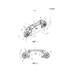
Фиг.1 представляет собой вид в перспективе варианта осуществления настоящего изобретения;Figure 1 is a perspective view of an embodiment of the present invention;
Фиг.2 представляет собой вид спереди устройства с Фиг.1;Figure 2 is a front view of the device of Figure 1;
Фиг.3 представляет собой вид справа устройства с Фиг.1;Figure 3 is a right side view of the device of Figure 1;
Фиг.4 представляет собой вид сверху устройства с Фиг.1;Figure 4 is a top view of the device of Figure 1;
Фиг.5 представляет собой вид в разрезе по линии 5-5 с Фиг.4; иFigure 5 is a sectional view taken along line 5-5 of Figure 4; and
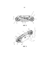
Фиг.6 представляет собой вид в перспективе варианта устройства с Фиг.1.Fig.6 is a perspective view of a variant of the device of Fig.1.
На чертежах показаны два устройства для управления подачей нити согласно изобретению, соответственно, на Фиг.1-5 и Фиг.6. Далее в этом документе, со ссылкой на фиг.1-5, описано только первое из этих устройств, поскольку второе (Фиг.6) отличается от первого только своей внешней конфигурацией, а не техническими характеристиками. Конечно же, то, что обозначено как отличительный признак на Фиг.1-5, также относится к устройству на Фиг.6.The drawings show two devices for controlling the filament according to the invention, respectively, in Fig.1-5 and Fig.6. Further in this document, with reference to FIGS. 1-5, only the first of these devices is described, since the second (FIG. 6) differs from the first only in its external configuration, and not in its technical characteristics. Of course, what is designated as the hallmark of FIGS. 1-5 also applies to the device of FIG. 6.
Как видно на упомянутых выше чертежах, устройство согласно изобретению содержит основную часть 1, которая в варианте осуществления на чертежах является, по существу, пластинообразной, удлиненной по ее продольной оси X и имеющей противоположные поверхности 2 и 3. Под термином "по существу пластинообразная" понимается факт того, что протяженность основной части 1 вдоль оси X значительно превышает протяженность вдоль оси Y, перпендикулярной оси X, то есть перпендикулярной поверхностям 2 и 3.As can be seen in the above drawings, the device according to the invention comprises a
На поверхности 2 основной части 1 установлены два вращающихся неприводных элемента 5 и 6.On the
Вращающиеся элементы 5 и 6 имеют оси K вращения, параллельные друг другу, лежащие в той же плоскости, что и ось X. Эти элементы имеют канавку 10, в которой может скользить нить F, подаваемая к обрабатывающей машине (не показана). Упомянутая нить может представлять собой текстильную нить или металлическую нить, и обрабатывающая машина может представлять собой как ткацкий станок, так и катушечную или намоточную машину. Нить разматывается с ее опоры, которая может представлять собой бобину или часть элемента для подачи нити к машине. Такая нить может быть перемещена с опоры к машине или наоборот.The
Нить на своем пути встречается с вращающимися элементами 5 и 6 (соответственно, для входа в устройство, которое является объектом изобретения, и выхода из него) и ее движение естественным образом приводит их во вращение.The thread on its way meets the
Каждый из последних взаимодействует с датчиком 12, который определяет его вращение. Такой датчик 12, показанный только в качестве примера на Фиг.1 и 2, может быть любого типа, например один или более датчиков Холла, взаимодействующих с одним или более магнитами, связанными с соответствующим вращающимся элементом; как вариант он может представлять собой оптический или магнитный энкодер, или энкодер другого типа.Each of the latter interacts with a
Датчики 12 соединены с блок 13 управления нитью, схематично показанным на Фиг.5, выполненным с возможностью измерения, посредством сигналов, исходящих от самих датчиков 12, скорости вращения каждого из упомянутых элементов и, следовательно, непрямо, количества нити или пряжи, перемещаемой на упомянутом элементе. Предпочтительно, с помощью сигналов, идущих от датчиков 12, узел управления может измерять не только количество, но также и направление скольжения нити, следовательно, обладая возможностью измерения величины скольжения нити по упомянутым элементам 5 и 6 в направлении ткацкого станка и величину ее скольжения в противоположном направлении.The
Преимущественно, узел 13 выполнен с возможностью самостоятельного понимания различных этапов работы машины (ткацкой или работающей с металлической нитью) с помощью информации о скорости нити и информации о количестве подаваемой нити, определяемой посредством датчиков 12.Mostly, the
Датчик 15 натяжения, соединенный с узлом 13, может быть датчиком любого типа, например тензодатчиком, и он взаимодействует с нитью в то время как она проходит от одного вращающегося элемента к другому.The
Благодаря датчику 15, узел 13 управления подачей может проверять развитие или изменение натяжения нити во время подачи нити, в частности, отслеживать среднее или мгновенное значение этой величины для проверки того, что она остается в заданном поле допуска. Если это не определяется, генератор сигнала тревоги, соединенный с узлом 13, предпочтительно образует звуковой и/или визуальный сигнал тревоги.Thanks to the
Следовательно, узел 13 через вращающиеся элементы 5 и 6 измеряет количество нити F, подаваемой к ткацкому станку. В частности, элемент 5 принимает нить от бобины или эквивалентного устройства подачи (не показано), тогда как элемент 6 отправляет эту нить к обрабатывающей машине.Therefore, the
Следовательно, узел 13, с помощью датчиков 12, связанных с вращающимися элементами 5 и 6, определяет и измеряет подаваемое количество нити и скорость подачи и сравнивает их с заданными величинами, хранимыми в самом узле или в памяти узла, с которой он взаимодействует. Если между определяемой величиной и хранимой величиной существует расхождение, узел 13 предпочтительно образует звуковой и/или визуальный сигнал тревоги с помощью упомянутого генератора сигнала тревоги.Therefore, the
В частности, такие заданные и хранимые величины могут быть фиксированными, предварительно заданными или самообучаемыми во время выполнения образца или производимого продукта, который проверен или принят. Такие величины также могут быть изменяемыми (и не фиксированными) как функция конкретных этапов работы такой машины.In particular, such set and stored values may be fixed, pre-set or self-learning during the execution of a sample or manufactured product that has been tested or accepted. Such quantities can also be variable (and not fixed) as a function of the specific stages of the operation of such a machine.
Следовательно, узел 13, продолжающий отслеживать сигналы, идущие от датчиков 12 и от датчика 15, может осуществлять отслеживание и перехват любой неправильности, связанной с натяжением или с количеством нити, подаваемой к ткацкому станку во время работы.Therefore, the
В частности, посредством отслеживания информации, идущей от датчика 15 натяжения, он может проверять, чтобы измеренное натяжение нити лежало в предварительно заданном, заданном или самообучаемом диапазоне. Узел 13 управления может преимущественно использовать мгновенную величину измерения или его (среднюю) отфильтрованную величину для перехвата неправильностей, таких как внезапные изменения (пики натяжения) или медленные изменения (смещения по причине, например, изменения трения нормальных направляющих нити, присутствующих вдоль пути нити).In particular, by monitoring the information coming from the
Посредством отслеживания только информации, идущей от датчиков 12 вращения, узел 13 управления может определять, скользит ли нить или нет, и, возможно, также направление скольжения. Узел 13 управления может использовать информацию "нить скользит" для самосинхронизации управления натяжением, например, для проверки того, что датчик активен только во время действительных этапов производства.By monitoring only information coming from the
Следовательно, узел 13 управления, посредством обработки информации, идущей от датчиков 12, может измерять скорость нити и, следовательно, количество подаваемой нити, с абсолютной точностью. Узел управления может использовать эту информацию для отслеживания нахождения этой информации в предварительно заданном или самообучаемом интервале, во время выполнения ранее запущенного этапа изготовления образца, в результате которого получен проверенный и принятый образец готового продукта. В этом случае это также происходит посредством использования мгновенных или отфильтрованных величин для перехвата разных аварийных ситуаций.Therefore, the
К тому же, при наличии двух датчиков 12 перемещения, узел 13 управления может преимущественно отслеживать дифференциал между величиной скорости на входе в основную часть 1 и величиной скорости на выходе из основной части 1 устройства. На самом деле, дифференциал скорости, имеющий большую величину или изменяющийся со временем (медленно или внезапно), может означать проблему во время выполнения этапа изготовления.In addition, if there are two
В частности, с помощью анализа дифференциала скорости, узел 13 управления может перехватывать механические неполадки устройства, являющегося объектом изобретения, например, если один из двух шкивов 5 и 6 не вращается правильно, или если датчик 15 натяжения поврежден или загрязнен и, таким образом, вызывает избыточное трение в точке соприкосновения.In particular, by analyzing the speed differential, the
Анализ дифференциала также может быть использован для перехвата неправильностей процессов изготовления. Например, посредством отслеживания нити, покрытой парафином, датчик может проверять, чтобы количество парафина на нити F было постоянным и не изменялось во времени. Изменение парафина приводит к изменению коэффициента скольжения нити и, следовательно, к изменению трения по керамической части датчика натяжения и, как следствие, к дифференциалу скорости между входным вращающимся элементом 5 и выходным вращающимся элементом 6.Differential analysis can also be used to intercept manufacturing process irregularities. For example, by monitoring a paraffin coated thread, the sensor can verify that the amount of paraffin on thread F is constant and does not change over time. A change in paraffin leads to a change in the slip coefficient of the thread and, consequently, to a change in friction along the ceramic part of the tension sensor and, as a result, to a speed differential between the
Дифференциал скорости также может означать неправильное прохождение нити внутри устройства согласно изобретению (например, нить не проходит правильно по вращающимся элементам 5, 6 или по датчику 15 натяжения).The differential speed can also mean incorrect passage of the thread inside the device according to the invention (for example, the thread does not pass correctly on the
Узел 13 управления также может использовать измеренную величину количества/скорости для автоматического изменения контрольных порогов натяжения и самого количества/скорости как функции количества/скорости подаваемой нити для обеспечения оптимального управления подачей нити F как функции разных этапов работы.The
Дифференциал также может быть использован для измерения коэффициента удлинения или упругости самой нити F, учитывая, что прохождение по датчику 15 натяжения вызывает трение и, следовательно, удлинение нити, которое может быть измерено с помощью дифференциала скорости между входным шкивом и выходным шкивом.The differential can also be used to measure the elongation or elasticity coefficient of the filament itself F, given that the passage through the
К тому же, комбинация датчика 15 натяжения и измерения количества/скорости подаваемой нити позволяет получать счетчики метража, обладающие очень высокой точностью, поскольку изменение натяжения вызывает удлинение измеряемой нити F как функцию прилагаемого или измеряемого натяжения; следовательно, величина измеренного количества нити может быть автоматически уравновешена как функция самого натяжения. Например, посредством использования нити с фактором удлинения 5%, в процессе используются измерения количества нити с погрешностями, которые никогда не составляют меньше этих 5%. Измерение натяжения нити во время процесса одновременно с измерением количества нити, наоборот, позволяет применять фактор уравновешивания к измеренным длинам нити как функцию считанного натяжения. Например, в иллюстративном случае заданной итоговой метрической величины 1000 м при среднем натяжении 5 г, и управлении нитью, которая при 1 г натяжения имеет удлинение 1%, а при натяжении 10 г имеет максимальное удлинение 5%, устройство согласно изобретению как функция измеренного натяжения может уравновешивать некоторое количество нити в реальном времени, исправляя измерение самого процентного отношения.In addition, the combination of the
Например, 1000 м при 1 г преобразуется в 1000+0,04×1000=1040 м; тогда как 1000 м при 10 г преобразуется в 1000-0,05⋅1000=950 м.For example, 1000 m at 1 g is converted to 1000 + 0.04 × 1000 = 1040 m; while 1000 m at 10 g is converted to 1000-0.05-1000 = 950 m.
Таким образом, возможно изготовить счетчики метража с погрешностью значительно меньше 1%, даже в случае пряж со значительным коэффициентом удлинения.Thus, it is possible to produce meter meters with an error significantly less than 1%, even in the case of yarns with a significant elongation coefficient.
Наконец, информация, относящаяся к натяжению и скорости/количеству нити F, подаваемой в процесс, может быть использована для замыкания комплексных регулировочных контуров, как тех, которые описаны в WO2013/045982.Finally, information relating to the tension and speed / number of threads F fed to the process can be used to close complex control loops, such as those described in WO2013 / 045982.
Узел 13 управления может быть вставлен в основную часть 1 (как видно на Фиг.5).The
Узел 13 управления может предусматривать использование входа 20 в качестве сигнала синхронизации, с помощью которого узел 13 включает и выключает отслеживание нахождения в поле параметров (натяжения и скорости/количества подаваемой нити) только во время действительного использования нити такой машиной.The
Предпочтительно, узел 13 может выполнять управление на основе предварительно заданных параметров, которые являются функцией рабочей фазы машины. Это возможно благодаря сигналу синхронизации, который идет через соединение или вход 20, который позволяет такому узлу проверять упомянутую рабочую фазу: например, узел проверяет количество подаваемой нити F для каждого швейного стежка и сравнивает его с соответствующими хранимыми параметрами, запрограммированными или самообучаемыми, и выполняет такую проверку, как функцию изготовленной части продукта, например носка с цветными вставками, во время производственной фазы. Если между определяемым значением и запрограммированным или предварительно заданным значением существует разница, узел 13 приводит в действие звуковой и/или визуальный сигнал тревоги.Preferably, the
Основная часть 1 может иметь такое же соединение 20 или дополнительный вход (или окно) 26 (схематично показанный на Фиг.1) для соединения с устройством согласно изобретению линии последовательной передачи данных (соединение через кабель или Wi-Fi); посредством этого соединения, информация, определяемая узлом 13, может быть также передана удаленно к центру сбора информации для возможной дальнейшей ее обработки. В это же время, через внешний интерфейс возможно задавать контрольные величины, и упомянутый внешний интерфейс может представлять собой портативный компьютер, терминал, планшет или смартфон.The
Наконец, выше описано решение, в котором устройство согласно изобретению имеет узел 13 управления внутри своей основной части 1. Тем не менее, в упрощенной форме, последнее не содержит упомянутый узел, а имеет три (аналоговых/цифровых) выхода сигнала относительно измеренного натяжения и скорости двух вращающихся элементов 5 и 6. Такая информация может проходить, через кабель, к удаленному узлу управления, к которому возможно прибывает другая информация, соответствующая другим устройствам, аналогичным описанному выше, работающим на разных нитях обрабатывающей машины (например, на нитях трикотажной машины); такой удаленный узел управления принимает всю информацию, сравнивает ее с соответствующими хранимыми и предварительно заданными величинами для управления качеством рабочего процесса, выполняемого посредством упомянутых нитей F или для замыкания комплексных регулировочных контуров, как тех, которые описаны в WO2013/045982.Finally, the solution described above is described in which the device according to the invention has a
Следовательно, изобретение представляет собой компактное устройство, выполненное с возможностью обеспечения оптимального управления подачей нити из бобины к такому устройству и от устройства к ткацкому станку. Таким образом, благодаря устройству, описанному в этом документе, могут быть предусмотрены два контура для регулировки подачи нити с единственным элементом, использующим два вращающихся подающих элемента и единственный датчик натяжения, расположенный между ними. Это увеличивает простоту изготовления устройства управления подачей, а также улучшает его надежность и уменьшает его стоимость.Therefore, the invention is a compact device, made with the possibility of providing optimal control of the filament from the bobbin to such a device and from the device to the weaving machine. Thus, thanks to the device described in this document, two loops can be provided for adjusting the filament feed with a single element using two rotating feed elements and a single tension sensor located between them. This increases the ease of manufacture of the feed control device, and also improves its reliability and reduces its cost.
Благодаря изобретению, может быть осуществлен способ для управления подачей нити, который содержит определение множества измерений скорости, натяжения и количества подаваемой нити и замыкание комплексного множества контуров регулировки и контуров управления с высокой точностью (счетчик метража) для подачи нити, в которых итоговый результат является функцией комбинации самих измерений.Thanks to the invention, a method for controlling the filing of a thread can be implemented, which comprises determining a plurality of measurements of speed, tension and quantity of filing filament and closing a complex set of control loops and control loops with high accuracy (meter counter) for filing a filament, in which the final result is a function combinations of the measurements themselves.
В свете предшествующего описания могут быть получены другие варианты осуществления изобретения, например, более в общем, такие, в которых предусмотрено множество вращающихся элементов, вблизи от которых расположены один или более датчиков натяжения, причем упомянутые вращающиеся элементы, расположенные в каскаде вдоль пути нити, все связаны с основной частью 1 (между ними могут быть расположены соответствующие датчики натяжения). Также такие варианты осуществления должны лежать в объеме прилагаемой формулы изобретения.In the light of the preceding description, other embodiments of the invention can be obtained, for example, more generally, those in which a plurality of rotating elements are provided, adjacent to which one or more tension sensors are located, said rotating elements located in a cascade along the thread path, all connected to the main part 1 (between them, appropriate tension sensors can be located). Also, such embodiments should be within the scope of the appended claims.
Claims (13)
1. Компактное устройство для управления подачей тканевой или металлической нити, которая разматывается с соответствующей опоры к обрабатывающей машине, такой как ткацкий станок или катушечная или намоточная машина, причем упомянутая подача может происходить от опоры к машине и от последней к опоре, причем упомянутое устройство содержит основную часть (1), несущую по меньшей мере два вращающихся элемента (5, 6), по которым проматывается нить и с которыми связано средство (12) определения для определения скорости их вращения, причем это средство (12) определения соединено с узлом (13) управления, причем предусмотрено средство (15) для определения натяжения нити, которое соединено с упомянутым узлом (13), причем каждый из упомянутых вращающихся элементов (5, 6) является неприводным и приводится во вращение посредством нити, которая перемещается по нему, причем средство (15) определения натяжения присутствует вблизи от него, отличающееся тем, что в нем предусмотрены два неприводных вращающихся элемента (5, 6), выполненные с возможностью измерения количества и скорости подаваемой нити, приводимые во вращение нитью, которая перемещается по ним, причем средство (15) определения натяжения находится между ними, причем узел (13) управления определяет состояние скольжения и покоя нити (F), ее скорость и/или количество подаваемой нити и направление скольжения нити (F), то есть перемещается ли она к обрабатывающей машине или перемещается ли она от последней.
1. A compact device for controlling the supply of fabric or metal thread, which is unwound from a suitable support to a processing machine, such as a weaving machine or a bobbin or winding machine, said feeding may be from a support to the machine and from the latter to the support, said device comprising the main part (1), bearing at least two rotating elements (5, 6), on which the thread is rolled and with which the means (12) of determining are determined for determining the speed of their rotation, and this means about (12) definitions connected to the node (13) control, and provides means (15) for determining the tension of the thread, which is connected to the said node (13), and each of these rotating elements (5, 6) is non-driven and rotated by means of a thread that moves along it, and the means (15) for determining the tension is present close to it, characterized in that it has two non-driving rotating elements (5, 6), configured to measure the quantity and speed of the supplied thread, which are rotated by the thread that moves along them, and the means (15) for determining the tension is between them, and the control unit (13) determines the sliding and quiescent state of the thread (F), its speed and / or the amount of supplied thread and the direction of sliding of the thread ( F), i.e. whether it moves to the processing machine or whether it moves from the latter.
7. Устройство по п.1, отличающееся тем, что узел (13) управления соединен с датчиками натяжения и количества и скорости подаваемой нити других аналогичных устройств, которые, тем не менее, работают на множестве разных нитей, которые все подаются к одной обрабатывающей машине, причем упомянутый узел (13) принимает всю информацию, относящуюся к контролируемым натяжениям, скоростям и количествам нитей и сравнивает ее с соответствующими хранимыми и предварительно заданными величинами, причем упомянутый выше узел (13) оказывает воздействие на единственное устройство для управления качеством рабочего процесса, работающего с таким множеством нитей (F), и/или для регулировки подачи последних к такой машине с автономными комплексными контурами для регулировки натяжения и/или скорости при работе с отдельными нитями.6. The device according to claim 5, characterized in that the said control unit (13) independently understands the various stages of the machine operation by means of information about the speed of the thread and information about the quantity of the supplied thread, determined using the said means (12) for determining the speed.
7. The device according to claim 1, characterized in that the control unit (13) is connected to the sensors of tension and the quantity and speed of the supplied thread of other similar devices, which, however, operate on many different threads, which are all fed to one processing machine moreover, said node (13) takes all the information related to controlled tension, speed and number of threads and compares it with the corresponding stored and pre-set values, and the above node (13) has an effect on A device for controlling the quality of the work process working with so many threads (F), and / or for adjusting the supply of the latter to such a machine with autonomous integrated circuits for adjusting tension and / or speed when working with individual threads.
Applications Claiming Priority (3)
| Application Number | Priority Date | Filing Date | Title |
|---|---|---|---|
| IT001662A ITMI20131662A1 (en) | 2013-10-08 | 2013-10-08 | COMPACT DEVICE FOR CHECKING THE WIRE SUPPLY TO A OPERATING MACHINE |
| ITMI2013A001662 | 2013-10-08 | ||
| PCT/IB2014/065032 WO2015052624A1 (en) | 2013-10-08 | 2014-10-03 | Compact device for controlling the supply of thread to a processing machine |
Publications (3)
| Publication Number | Publication Date |
|---|---|
| RU2016117791A RU2016117791A (en) | 2017-11-15 |
| RU2016117791A3 RU2016117791A3 (en) | 2018-05-10 |
| RU2660671C2 true RU2660671C2 (en) | 2018-07-09 |
Family
ID=49640007
Family Applications (1)
| Application Number | Title | Priority Date | Filing Date |
|---|---|---|---|
| RU2016117791A RU2660671C2 (en) | 2013-10-08 | 2014-10-03 | Compact device for controlling the supply of thread to a processing machine |
Country Status (9)
| Country | Link |
|---|---|
| US (1) | US9845219B2 (en) |
| EP (1) | EP3055242B1 (en) |
| JP (1) | JP6417411B2 (en) |
| CN (1) | CN105612117B (en) |
| ES (1) | ES2665449T3 (en) |
| IT (1) | ITMI20131662A1 (en) |
| RU (1) | RU2660671C2 (en) |
| TW (1) | TWI658984B (en) |
| WO (1) | WO2015052624A1 (en) |
Families Citing this family (9)
| Publication number | Priority date | Publication date | Assignee | Title |
|---|---|---|---|---|
| USD794683S1 (en) * | 2015-09-15 | 2017-08-15 | Btsr International S.P.A. | Yarn feeder |
| USD794715S1 (en) * | 2015-09-15 | 2017-08-15 | Btsr International S.P.A. | Yarn feeder |
| WO2018224398A1 (en) * | 2017-06-07 | 2018-12-13 | Oerlikon Textile Gmbh & Co. Kg | Method and device for monitoring a yarn tension of a running yarn |
| IT201700086095A1 (en) | 2017-07-27 | 2019-01-27 | Btsr Int Spa | METHOD AND SYSTEM FOR FEEDING A WIRED AND BRAIDED METALLIC CABLE OR A FLAT WIRE FROM A RELATIVE SUPPORT WITHOUT MODIFY STRUCTURE OR CONFORMATION OF THE WIRE |
| KR20190036234A (en) * | 2017-09-27 | 2019-04-04 | 주식회사 마이크로오토메이션 | Apparatus for exercise quantity measurement |
| NO20171695A1 (en) * | 2017-10-20 | 2019-04-22 | Wilhelmsen Ships Service As | A smart line sensor |
| EP3737943A1 (en) | 2018-01-09 | 2020-11-18 | Oerlikon Textile GmbH & Co. KG | Method and device for monitoring a texturing process |
| CN108502630A (en) * | 2018-05-25 | 2018-09-07 | 苏州七瑾年新材料科技有限公司 | A kind of production of chemical fibre winding device |
| CN108803521B (en) * | 2018-06-26 | 2020-03-06 | 康赛妮集团有限公司 | Continuous intelligent flexible production method for carded wool spinning |
Citations (6)
| Publication number | Priority date | Publication date | Assignee | Title |
|---|---|---|---|---|
| SU417361A1 (en) * | 1971-03-04 | 1974-02-28 | П. В. Ползик, В. А. Палагин, В. Н. Станишевский, В. Д. Лебедев, Э. И. Гаража, А. Н. Савельев , А. М. Булавчиков | DEVICE FOR AUTOMATIC STABILIZATION THREAD TENSION |
| US4163126A (en) * | 1978-03-09 | 1979-07-31 | W. C. Dillon And Co. Inc. | Tension indicating device |
| JPH10115565A (en) * | 1996-09-03 | 1998-05-06 | W Schlafhorst Ag & Co | Apparatus for measuring thread tension of running thread |
| DE10101747A1 (en) * | 2000-01-19 | 2001-07-26 | Zitec Ag Oberwil | Yarn monitor has measurement arms projecting from a housing with a wheel which is rotated by the moving yarn to measure yarn tension and other parameters such as speed and yarn length |
| WO2002088013A1 (en) * | 2001-04-10 | 2002-11-07 | Iropa Ag | Thread tension measuring device based on a photoelastic measuring principle |
| WO2013045982A1 (en) * | 2011-06-08 | 2013-04-04 | Btsr International S.P.A. | Method and device for feeding a thread to a textile machine with constant tension and constant velocity or quantity |
Family Cites Families (24)
| Publication number | Priority date | Publication date | Assignee | Title |
|---|---|---|---|---|
| FR1525163A (en) * | 1967-03-17 | 1968-05-17 | Ambassades | Voltage-dependent flow control device |
| JPS5123698Y2 (en) * | 1972-04-18 | 1976-06-18 | ||
| US4241616A (en) * | 1979-09-11 | 1980-12-30 | W. C. Dillon & Co., Inc. | Tensiometer capable of being attached to a cable under tension |
| US4492363A (en) * | 1979-12-20 | 1985-01-08 | Niskin Shale J | Multiple pulley sheave assembly with retainer pulleys |
| SE436799B (en) * | 1981-04-07 | 1985-01-21 | Ohrnell Teknik Hb | ELECTRONIC SENSOR ELEMENT PROVIDED TO BE APPLIED ON A LINE EXPOSED |
| JPS5831897A (en) * | 1981-08-19 | 1983-02-24 | 東亜発動機株式会社 | Winder for wire rope |
| US4833927A (en) * | 1983-07-01 | 1989-05-30 | Teleco Oilfield Services Inc. | Cable tensiometer |
| US4992778A (en) * | 1989-12-22 | 1991-02-12 | The University Of New Mexico | Pre-failure tension warning device |
| US5305649A (en) * | 1992-04-13 | 1994-04-26 | Halliburton Company | Cable length and tension measuring device |
| JPH06323842A (en) * | 1993-05-11 | 1994-11-25 | Shimpo Ind Co Ltd | Winding diameter arithmetic equipment |
| DE59405907D1 (en) * | 1994-06-10 | 1998-06-10 | Rueti Ag Maschf | Device for measuring thread tension and weaving machine |
| CN1224689A (en) * | 1998-01-30 | 1999-08-04 | 村田机械株式会社 | Yarn take-up winder |
| JPH11208994A (en) * | 1998-01-30 | 1999-08-03 | Murata Mach Ltd | Spun yarn winder |
| US6134974A (en) * | 1998-06-23 | 2000-10-24 | Montech Systems, Inc. | Incremental filament tension measurement device and method |
| US6895811B2 (en) * | 2001-12-14 | 2005-05-24 | Shawmut Corporation | Detection of small holes in laminates |
| US6901818B1 (en) * | 2002-12-05 | 2005-06-07 | Maxwell C. Cheung | Tension measuring device for mooring line |
| US6991144B2 (en) * | 2004-02-04 | 2006-01-31 | The Procter & Gamble Company | Method of controlling tension in a moving web material |
| FR2888157B1 (en) * | 2005-07-08 | 2009-10-09 | Michelin Soc Tech | METHOD OF REGULATING TENSION OF A PNEUMATIC REINFORCEMENT |
| DE102005058142A1 (en) * | 2005-12-06 | 2007-06-21 | Voith Patent Gmbh | Method for determining a stretching property of a paper web |
| ITMI20072269A1 (en) * | 2007-12-04 | 2009-06-05 | Btsr Int Spa | METHOD AND ARRANGEMENT FOR CONSTANT WIRE LENGTH SUPPLEMENT OF A TEXTILE MACHINE OPERATING ON A PLURALITY OF WIRES |
| JP5123698B2 (en) * | 2008-03-07 | 2013-01-23 | 寿照 河内 | Parent tug |
| JP2011141463A (en) * | 2010-01-08 | 2011-07-21 | Oki Data Corp | Image forming apparatus and medium conveying method |
| ES2401809B1 (en) * | 2011-10-11 | 2014-01-30 | Dinacell Electrónica, Sl | SENSOR FOR MEASURING MECHANICAL VOLTAGES, ADAPTABLE TO DIFFERENT CALIBER CABLES |
| US9404566B2 (en) * | 2013-09-05 | 2016-08-02 | Randal Salvatore | Power measurement system based on self-limiting force |
-
2013
- 2013-10-08 IT IT001662A patent/ITMI20131662A1/en unknown
-
2014
- 2014-10-03 CN CN201480055139.4A patent/CN105612117B/en active Active
- 2014-10-03 RU RU2016117791A patent/RU2660671C2/en active
- 2014-10-03 JP JP2016521336A patent/JP6417411B2/en active Active
- 2014-10-03 US US15/023,759 patent/US9845219B2/en active Active
- 2014-10-03 ES ES14786359.1T patent/ES2665449T3/en active Active
- 2014-10-03 WO PCT/IB2014/065032 patent/WO2015052624A1/en active Application Filing
- 2014-10-03 EP EP14786359.1A patent/EP3055242B1/en active Active
- 2014-10-06 TW TW103134738A patent/TWI658984B/en active
Patent Citations (6)
| Publication number | Priority date | Publication date | Assignee | Title |
|---|---|---|---|---|
| SU417361A1 (en) * | 1971-03-04 | 1974-02-28 | П. В. Ползик, В. А. Палагин, В. Н. Станишевский, В. Д. Лебедев, Э. И. Гаража, А. Н. Савельев , А. М. Булавчиков | DEVICE FOR AUTOMATIC STABILIZATION THREAD TENSION |
| US4163126A (en) * | 1978-03-09 | 1979-07-31 | W. C. Dillon And Co. Inc. | Tension indicating device |
| JPH10115565A (en) * | 1996-09-03 | 1998-05-06 | W Schlafhorst Ag & Co | Apparatus for measuring thread tension of running thread |
| DE10101747A1 (en) * | 2000-01-19 | 2001-07-26 | Zitec Ag Oberwil | Yarn monitor has measurement arms projecting from a housing with a wheel which is rotated by the moving yarn to measure yarn tension and other parameters such as speed and yarn length |
| WO2002088013A1 (en) * | 2001-04-10 | 2002-11-07 | Iropa Ag | Thread tension measuring device based on a photoelastic measuring principle |
| WO2013045982A1 (en) * | 2011-06-08 | 2013-04-04 | Btsr International S.P.A. | Method and device for feeding a thread to a textile machine with constant tension and constant velocity or quantity |
Also Published As
| Publication number | Publication date |
|---|---|
| EP3055242A1 (en) | 2016-08-17 |
| CN105612117B (en) | 2019-11-29 |
| RU2016117791A3 (en) | 2018-05-10 |
| EP3055242B1 (en) | 2018-01-10 |
| JP2016533989A (en) | 2016-11-04 |
| RU2016117791A (en) | 2017-11-15 |
| TW201529461A (en) | 2015-08-01 |
| CN105612117A (en) | 2016-05-25 |
| JP6417411B2 (en) | 2018-11-07 |
| TWI658984B (en) | 2019-05-11 |
| US9845219B2 (en) | 2017-12-19 |
| US20160229659A1 (en) | 2016-08-11 |
| ITMI20131662A1 (en) | 2015-04-09 |
| WO2015052624A1 (en) | 2015-04-16 |
| ES2665449T3 (en) | 2018-04-25 |
Similar Documents
| Publication | Publication Date | Title |
|---|---|---|
| RU2660671C2 (en) | Compact device for controlling the supply of thread to a processing machine | |
| US9126799B2 (en) | Yarn storage feed device | |
| JP6002214B2 (en) | Method and apparatus for feeding yarn to a textile machine with constant tension and constant speed or quantity | |
| JP2016533989A5 (en) | ||
| WO1999036746A1 (en) | A method of determining the thickness and/or the homogeneity of a moving linear textile formation and a device for carrying out the method | |
| BRPI0713356A2 (en) | device for separating wires from a layer of wires, method for operating the device and use of the device | |
| CN104870351A (en) | Method and device for feeding a metal wire to an operating machine at a constant tension and quantity | |
| CN100422745C (en) | Method and device for contactless determination of the speed of a running thread of yarn | |
| CN201326073Y (en) | Warp knitting machine | |
| EP1332333A1 (en) | Device for optical yarn measurement | |
| TWI777555B (en) | An apparatus and a method for measuring width of moving fabric woven on a circular loom | |
| KR102528836B1 (en) | Winding of multiple elongated elements | |
| Narayana | Novel method for dynamic yarn tension measurement and control in direct cabling process | |
| KR102555593B1 (en) | Creel group control system | |
| JP3652901B2 (en) | Method and apparatus for measuring yarn tension | |
| DE19511527C2 (en) | Device for determining twisting parameters on a twisting machine, in particular a cabling machine | |
| Jihong et al. | Measurement of high rotating speed of ring spinning frame | |
| Cooray et al. | Mathematical modeling of over-end yarn withdrawl, and the development/design of a device for uniform unwinding tension | |
| IT201800007909A1 (en) | METHOD OF MEASURING YARN CONSUMPTION FOR ACCUMULATION WEFT FEEDERS | |
| JPS58207255A (en) | Abnormality sensing method for threads | |
| ITMI20090239U1 (en) | DEVICE FOR AUTOMATICALLY ASSESSING THE WIRE LENGTH ABSORBED BY A STRAIGHT MACHINE AND AUTOMATICALLY COMPENSATING THE FRICTIONS BY CHANGING THE POWER SUPPLY VOLTAGE | |
| ITMI20091037A1 (en) | METHOD AND DEVICE FOR AUTOMATICALLY ASSESSING THE WIRE LENGTH ABSORBED BY A STRAIGHT-SIDED MACHINE | |
| Shankam Narayana | A Novel Method for Dynamic Yarn Tension Measurement and Control in Direct Cabling Process | |
| WO2000020317A1 (en) | Method and arrangement in connection with a winder | |
| EP2284303A1 (en) | Rotary creel of a sample warping machine, sample warping machine and method for measuring a bobbin diameter |