RU2657391C2 - Turbomachine containing crankcase wear indicator - Google Patents
Turbomachine containing crankcase wear indicator Download PDFInfo
- Publication number
- RU2657391C2 RU2657391C2 RU2015151391A RU2015151391A RU2657391C2 RU 2657391 C2 RU2657391 C2 RU 2657391C2 RU 2015151391 A RU2015151391 A RU 2015151391A RU 2015151391 A RU2015151391 A RU 2015151391A RU 2657391 C2 RU2657391 C2 RU 2657391C2
- Authority
- RU
- Russia
- Prior art keywords
- crankcase
- wall
- plug
- wear indicator
- compressor
- Prior art date
Links
- 230000003628 erosive effect Effects 0.000 claims description 17
- 239000011248 coating agent Substances 0.000 claims description 5
- 238000000576 coating method Methods 0.000 claims description 5
- 238000002679 ablation Methods 0.000 claims description 4
- 230000000694 effects Effects 0.000 abstract description 2
- 239000000126 substance Substances 0.000 abstract 1
- 238000012544 monitoring process Methods 0.000 description 5
- 239000007799 cork Substances 0.000 description 3
- 239000000463 material Substances 0.000 description 3
- 230000008439 repair process Effects 0.000 description 3
- 238000000034 method Methods 0.000 description 2
- 239000002245 particle Substances 0.000 description 2
- 238000010521 absorption reaction Methods 0.000 description 1
- 238000005452 bending Methods 0.000 description 1
- 230000000903 blocking effect Effects 0.000 description 1
- 238000002485 combustion reaction Methods 0.000 description 1
- 230000006835 compression Effects 0.000 description 1
- 238000007906 compression Methods 0.000 description 1
- 239000000428 dust Substances 0.000 description 1
- 238000001839 endoscopy Methods 0.000 description 1
- 239000003550 marker Substances 0.000 description 1
- 238000005259 measurement Methods 0.000 description 1
- 239000004576 sand Substances 0.000 description 1
- 239000007787 solid Substances 0.000 description 1
- 230000003068 static effect Effects 0.000 description 1
- 230000000007 visual effect Effects 0.000 description 1
Images
Classifications
-
- F—MECHANICAL ENGINEERING; LIGHTING; HEATING; WEAPONS; BLASTING
- F01—MACHINES OR ENGINES IN GENERAL; ENGINE PLANTS IN GENERAL; STEAM ENGINES
- F01D—NON-POSITIVE DISPLACEMENT MACHINES OR ENGINES, e.g. STEAM TURBINES
- F01D21/00—Shutting-down of machines or engines, e.g. in emergency; Regulating, controlling, or safety means not otherwise provided for
- F01D21/14—Shutting-down of machines or engines, e.g. in emergency; Regulating, controlling, or safety means not otherwise provided for responsive to other specific conditions
-
- F—MECHANICAL ENGINEERING; LIGHTING; HEATING; WEAPONS; BLASTING
- F01—MACHINES OR ENGINES IN GENERAL; ENGINE PLANTS IN GENERAL; STEAM ENGINES
- F01D—NON-POSITIVE DISPLACEMENT MACHINES OR ENGINES, e.g. STEAM TURBINES
- F01D21/00—Shutting-down of machines or engines, e.g. in emergency; Regulating, controlling, or safety means not otherwise provided for
- F01D21/003—Arrangements for testing or measuring
-
- F—MECHANICAL ENGINEERING; LIGHTING; HEATING; WEAPONS; BLASTING
- F01—MACHINES OR ENGINES IN GENERAL; ENGINE PLANTS IN GENERAL; STEAM ENGINES
- F01D—NON-POSITIVE DISPLACEMENT MACHINES OR ENGINES, e.g. STEAM TURBINES
- F01D21/00—Shutting-down of machines or engines, e.g. in emergency; Regulating, controlling, or safety means not otherwise provided for
-
- F—MECHANICAL ENGINEERING; LIGHTING; HEATING; WEAPONS; BLASTING
- F04—POSITIVE - DISPLACEMENT MACHINES FOR LIQUIDS; PUMPS FOR LIQUIDS OR ELASTIC FLUIDS
- F04D—NON-POSITIVE-DISPLACEMENT PUMPS
- F04D27/00—Control, e.g. regulation, of pumps, pumping installations or pumping systems specially adapted for elastic fluids
- F04D27/001—Testing thereof; Determination or simulation of flow characteristics; Stall or surge detection, e.g. condition monitoring
-
- F—MECHANICAL ENGINEERING; LIGHTING; HEATING; WEAPONS; BLASTING
- F04—POSITIVE - DISPLACEMENT MACHINES FOR LIQUIDS; PUMPS FOR LIQUIDS OR ELASTIC FLUIDS
- F04D—NON-POSITIVE-DISPLACEMENT PUMPS
- F04D29/00—Details, component parts, or accessories
- F04D29/40—Casings; Connections of working fluid
- F04D29/42—Casings; Connections of working fluid for radial or helico-centrifugal pumps
- F04D29/4206—Casings; Connections of working fluid for radial or helico-centrifugal pumps especially adapted for elastic fluid pumps
-
- F—MECHANICAL ENGINEERING; LIGHTING; HEATING; WEAPONS; BLASTING
- F05—INDEXING SCHEMES RELATING TO ENGINES OR PUMPS IN VARIOUS SUBCLASSES OF CLASSES F01-F04
- F05D—INDEXING SCHEME FOR ASPECTS RELATING TO NON-POSITIVE-DISPLACEMENT MACHINES OR ENGINES, GAS-TURBINES OR JET-PROPULSION PLANTS
- F05D2220/00—Application
- F05D2220/30—Application in turbines
- F05D2220/32—Application in turbines in gas turbines
- F05D2220/329—Application in turbines in gas turbines in helicopters
-
- F—MECHANICAL ENGINEERING; LIGHTING; HEATING; WEAPONS; BLASTING
- F05—INDEXING SCHEMES RELATING TO ENGINES OR PUMPS IN VARIOUS SUBCLASSES OF CLASSES F01-F04
- F05D—INDEXING SCHEME FOR ASPECTS RELATING TO NON-POSITIVE-DISPLACEMENT MACHINES OR ENGINES, GAS-TURBINES OR JET-PROPULSION PLANTS
- F05D2260/00—Function
- F05D2260/80—Diagnostics
Landscapes
- Engineering & Computer Science (AREA)
- Mechanical Engineering (AREA)
- General Engineering & Computer Science (AREA)
- Structures Of Non-Positive Displacement Pumps (AREA)
- Supercharger (AREA)
Abstract
Description
Область техники, к которой относится изобретениеFIELD OF THE INVENTION
Предлагаемое изобретение относится к области турбомашин, более конкретно к области компрессоров газотурбинных двигателей, в частности к центробежным компрессорам. Предметом изобретения является устройство, которое позволяет простым способом определить состояние износа определенных частей турбомашины.The present invention relates to the field of turbomachines, and more particularly to the field of compressors of gas turbine engines, in particular to centrifugal compressors. The subject of the invention is a device that allows a simple way to determine the state of wear of certain parts of a turbomachine.
Уровень техникиState of the art
Газотурбинные двигатели, используемые для привода лопаточного колеса вертолета, состоят из воздушных трактов радиального или осевого течения для участка траектории.Gas turbine engines used to drive the helicopter blade wheel consist of air paths of radial or axial flow for a portion of the trajectory.
Например, известный двигатель содержит первую крыльчатку, состоящую, например, из двух последовательных центробежных компрессоров - этот комплект приводится в действие осевой турбиной – и вторую крыльчатку свободной турбины, ниже по потоку турбины первой крыльчатки, для привода вала отбора мощности.For example, a known engine comprises a first impeller, for example, consisting of two successive centrifugal compressors — this set is driven by an axial turbine — and a second impeller of a free turbine, downstream of the first impeller, to drive a power take-off shaft.
Другой пример известного двигателя содержит первую крыльчатку, образованную комплектом из осевого трехступенчатого компрессора и центробежного компрессора, расположенных последовательно и приводимых двумя осевыми турбинами; вторая крыльчатка образована сдвоенной турбиной, которая получает газ от турбины первой крыльчатки и приводит в действие вал отбора мощности.Another example of a known engine comprises a first impeller formed by a set of an axial three-stage compressor and a centrifugal compressor arranged in series and driven by two axial turbines; the second impeller is formed by a twin turbine that receives gas from the turbine of the first impeller and drives the power take-off shaft.
В соответствии с формами использования этих типов летательных аппаратов, которые направляют их движение в атмосфере, загрязненной пылью и песком, двигатели подвергаются сильной эрозии твердыми частицами, всасываемыми вместе с поступающим воздухом.In accordance with the forms of use of these types of aircraft, which direct their movement in an atmosphere contaminated by dust and sand, the engines undergo severe erosion by solid particles absorbed together with the incoming air.
Большое внимание отводится деталям, чувствительным к воздействию эрозии, так чтобы принять необходимые меры в случае необходимости.Much attention is given to parts sensitive to the effects of erosion, so as to take the necessary measures if necessary.
В указанных выше типах двигателей любой воздушный тракт может подвергаться эрозии, в частности лопатки, но также статические участки воздушного тракта, например изгиб на центробежном двухкаскадном компрессоре, представляющий зону выхода диффузора первой ступени, или также картер на аксиально-центробежном компрессоре с абляционным покрытием или без оного напротив верхних частей лопаток на осевом компрессоре.In the above types of engines, any air path can undergo erosion, in particular vanes, but also static sections of the air path, for example, a bend on a centrifugal two-stage compressor, representing the exit zone of the first stage diffuser, or also a crankcase on an axial-centrifugal compressor with or without ablative coating thereof opposite the upper parts of the blades on an axial compressor.
Предметом изобретения является устройство, которое позволяет детектировать и определить величину эрозии, вызванную всасыванием частиц в воздушный тракт.The subject of the invention is a device that allows you to detect and determine the amount of erosion caused by the absorption of particles into the air duct.
Также является предметом изобретения устройство, которое не требует обязательного демонтажа двигателя.Also a subject of the invention is a device that does not require the dismantling of the engine.
Изобретение относится более конкретно к определенным зонам воздушного тракта, которые не подвергаются сильной эрозии и для которых желательным является упрощенный мониторинг. Речь идет, например, о внутренней стенке изгиба ниже диффузора с покрытием из абляционного материала или о картере без такого покрытия, напротив верхних частей лопаток крыльчатки осевого компрессора.The invention relates more particularly to certain areas of the airway that are not subject to severe erosion and for which simplified monitoring is desirable. We are talking, for example, about the inner wall of the bend below the diffuser coated with ablative material or about the crankcase without such a coating, opposite the upper parts of the impeller blades of the axial compressor.
Заявитель уже зарегистрировал заявку на патент FR 1159071 от 7 октября 2011 г., относящуюся к центробежному компрессору, оборудованному маркером измерения износа. Согласно его реализации крышка лопаточного колеса компрессора включает с внутренней стороны абляционное покрытие, содержащее по существу в его срединной части маркеры, выполненные в форме выточки и с заданной глубиной в абляционном материале. Мониторинг износа осуществляют путем контроля посредством эндоскопии. Эндоскоп вставляют в компрессор и активный конец эндоскопа позиционируют напротив меток, чтобы выдавать сигнал изображения меток. Эндоскопный сигнал зависит от числа маркеров и износа в зоне последних; его обрабатывают, чтобы получить критерий принятия решения о демонтаже двигателя для замены и ремонта изношенных деталей. По тематике сигнализатора износа были предложены другие патентные заявки, такие как FR 2938651 или FR 2946267, которые относятся к сигнализаторам износа, предусмотренным на лопатках колеса компрессора или на самом лопаточном колесе.The applicant has already filed patent application FR 1159071 dated October 7, 2011, relating to a centrifugal compressor equipped with a wear measurement marker. According to its implementation, the cover of the compressor blade wheel includes, on the inside, an ablation coating containing essentially in its middle part markers made in the form of a recess and with a predetermined depth in the ablation material. Wear monitoring is carried out by monitoring through endoscopy. The endoscope is inserted into the compressor and the active end of the endoscope is positioned opposite the marks to give a signal image of the marks. The endoscopic signal depends on the number of markers and wear in the zone of the latter; it is processed to obtain a decision criterion for dismantling the engine to replace and repair worn parts. Other patent applications have been proposed on the subject of the wear indicator, such as FR 2938651 or FR 2946267, which relate to wear indicators provided on the blades of the compressor wheel or on the blade wheel itself.
Изложение сущности изобретенияSUMMARY OF THE INVENTION
В дополнение метода мониторинга динамики износа на крышке лопаточного колеса теперь предложено устройство, которое позволяет узнать износ определенных частей воздушного тракта простым визуальным обзором, без необходимости использования какой-либо контрольной аппаратуры.In addition to the method for monitoring the dynamics of wear on the cover of a blade wheel, a device has now been proposed that allows you to find out the wear of certain parts of the air duct with a simple visual overview, without the need for any control equipment.
Согласно изобретению турбомашина, содержащая картер с внутренней стенкой, ограничивающей воздушный тракт, и картер, содержащий, по меньшей мере, одно отверстие, которое входит в указанный воздушный тракт и образует проход для эндоскопа, причем отверстие во время работы турбомашины закрыто пробкой, которая имеет участок концевой поверхности, который обеспечивает продолжение внутренней стенки картера, отличающаяся тем, что сигнализатор износа внутренней стенки картера образует одно целое с пробкой или с внутренней стенкой картера вблизи пробки.According to the invention, a turbomachine comprising a crankcase with an inner wall defining an air path and a crankcase comprising at least one hole that enters said air path and forms an endoscope passage, the opening being closed by a plug during operation of the turbomachine, which has a section end surface, which ensures the continuation of the inner wall of the crankcase, characterized in that the wear indicator of the inner wall of the crankcase forms a whole with the plug or with the inner wall of the crankcase cork.
Благодаря изобретению представляется возможным простой, не требующий использования никакой аппаратуры, мониторинг износа в зонах турбомашины, которые непосредственно недоступны и которые прежде нуждались в операциях демонтажа и удаления двигателя. Сигнализатор износа позволяет легко решить, следует ли демонтировать или нет турбомашину для проведения ремонта.Thanks to the invention, it seems possible to simple, not requiring the use of any equipment, monitoring of wear in the areas of the turbomachine, which are directly inaccessible and which previously needed engine dismantling and removal operations. The wear indicator makes it easy to decide whether or not to dismantle the turbomachine for repairs.
Согласно одной форме осуществления сигнализатор износа имеет форму выточки, выполненной на указанном участке концевой поверхности пробки. Эта форма осуществления пригодна для применения, когда указанный участок поверхности пробки находится на уровне внутренней стенки картера. Предпочтительно, пробка выполнена из того же материала, что и он.According to one embodiment, the wear indicator is in the form of a recess made in the indicated portion of the end surface of the plug. This form of implementation is suitable for use when the indicated portion of the surface of the plug is at the level of the inner wall of the housing. Preferably, the cork is made of the same material as it is.
Согласно другой форме осуществления, сигнализатор износа представляет собой паз, выточенный во внутренней стенке картера, который может быть виден снаружи через указанное отверстие, образующее проход для эндоскопа. Согласно этой форме осуществления, пробка может не находиться на одном уровне с воздушным трактом.According to another embodiment, the wear indicator is a groove machined in the inner wall of the crankcase, which can be seen externally through said opening, forming a passage for the endoscope. According to this embodiment, the plug may not be at the same level with the airway.
Глубину выточки выбирают предпочтительно так, чтобы она соответствовала толщине внутренней стенки, которая может быть удалена в результате эрозии, в случае допустимой эрозии зоны. Таким образом, когда выточка не видна, следует понимать, что пришло время приступить к ремонту изделия.The depth of the groove is preferably chosen so that it corresponds to the thickness of the inner wall, which can be removed as a result of erosion, in the case of permissible erosion of the zone. Thus, when the undercut is not visible, it should be understood that the time has come to begin repairing the product.
Как указано выше, предметом изобретения является собственно центробежный компрессор, отверстие в котором, образующее проход для эндоскопа вместе с сигнализатором износа, расположено в изгибе ниже диффузора, на выходе ступени компрессора.As indicated above, the subject of the invention is a centrifugal compressor itself, an opening in which, forming an endoscope passage along with a wear indicator, is located in a bend below the diffuser, at the outlet of the compressor stage.
Изобретение относится также к осевому компрессору или осевой части компрессора, в которой отверстие, образующее проход для эндоскопа, расположено вблизи от абляционного покрытия, напротив верхних частей лопаток ротора компрессора.The invention also relates to an axial compressor or an axial part of a compressor, in which the hole forming the passage for the endoscope is located close to the ablation coating, opposite the upper parts of the compressor rotor blades.
Краткое описание чертежейBrief Description of the Drawings
На фиг.1 показан центробежный двухкаскадный газотурбинный двигатель, к которому применимо изобретение.Figure 1 shows a centrifugal two-stage gas turbine engine to which the invention is applicable.
На фиг.2 показана деталь двигателя с фиг.1 в изометрии с тангенциальным разрезом по его оси, на уровне изгиба воздушного тракта ниже первого диффузора, также показана эндоскопная пробка.In Fig.2 shows a detail of the engine of Fig.1 in an isometric view with a tangential section along its axis, at the level of the bend of the air path below the first diffuser, an endoscope plug is also shown.
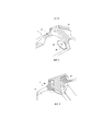
На фиг.3 показана в изометрии с тангенциальным разрезом по оси двигателя с видом изнутри, деталь эндоскопной пробки в положении на картере с выточкой, образующей сигнализатор износа по первой форме осуществления изобретения.Figure 3 shows in isometric view with a tangential cut along the axis of the engine with an inside view, a detail of the endoscope plug in position on the crankcase with a recess forming a wear indicator according to the first embodiment of the invention.
На фиг.4 показана деталь компрессора двигателя с фиг.1, с разрезом на уровне эндоскопной пробки, с сигнализатором износа по второй форме осуществления изобретения.Figure 4 shows a detail of the compressor of the engine of figure 1, with a cut at the level of the endoscope plug, with a wear indicator according to the second form of embodiment of the invention.
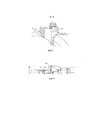
На фиг.5 показана деталь с фиг.4 без пробки.Figure 5 shows the detail of figure 4 without plugs.
На фиг.6 показан газотурбинный двигатель с осевым и центробежным компрессором, к которому также относится изобретение.6 shows a gas turbine engine with an axial and centrifugal compressor, to which the invention also relates.
Подробное описание вариантов осуществления изобретения Detailed Description of Embodiments
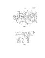
На фиг.1 показан известный газотурбинный двигатель 1 для привода лопаток ротора вертолета. Он содержит часть, образующую газогенератор с центробежным двухкаскадным компрессором, то есть соответственно с двумя лопаточными колесами сжатия 2 и 4, жестко соединенными с коаксиальной турбиной 6. Воздушный тракт 3 внутри картера - кольцевой и простирается от воздухозаборника 3а, который направляет воздух к осевому входу компрессора 2. Сжатый компрессором воздух направляется радиально через диффузор 3b. Дальше воздушный тракт 3 образует изгиб 3с, так что направляет воздух по оси машины к осевому входу второго лопаточного колеса компрессора 4. Затем воздух направляется в камеру сгорания 5, которая питает турбину 6 горячим газом. Происходит расширение газа в турбине 9 второго ротора, жестко соединенного с валом отбора мощности для привода нагрузки. Воздушный тракт ограничен двумя коаксиальными стенками, т.е. внутренней стенкой 3i картера 7.Figure 1 shows a known gas turbine engine 1 for driving rotor blades of a helicopter. It contains a part forming a gas generator with a centrifugal two-stage compressor, that is, respectively, with two
На фиг.2 изображен разрез части картера 7 двигателя с фиг.1, виден изгиб 3с воздушного тракта, ниже диффузора 3b. Этот изгиб служит для изменения направления воздушного потока, поступающего из диффузора на ось машины. В картере 7 на уровне изгиба 3с расположено радиальное отверстие 7r. Это отверстие выходит в воздушный тракт и обеспечивает проход непоказанного эндоскопа, посредством которого может быть осуществлен контроль внутри воздушного тракта. Это отверстие 7r обычно закрыто пробкой 8, которая показана в разрезе на фиг.2. Пробка содержит втулку 8f, которую подгоняют по отверстию 7r, так что она заполняет его и исключает утечки воздуха во время работы агрегата; втулка жестко соединена с блокирующей поперечной плитой 8v, через которую пробка сболчена с картером 7. С другой стороны, втулка пробки 8 имеет участок концевой поверхности 8s соответственно внутренней стенки 3i, так что обеспечивает ее продолжение. Figure 2 shows a section of part of the
Согласно изобретению сигнализатор износа размещен на пробке. Предпочтительно, он состоит из выточки 8l, выполненной на участке поверхности 8s пробки. Форма выточки может быть круглой, овальной или любого другого профиля. Эту выточку 81 можно видеть на фиг.3. Глубина выточки соответствует потенциалу эрозии внутренней стенки 3i. Таким образом, можно легко проверить состояние износа изделия. Если выточка не видна при демонтаже пробки 8, это означает, что потенциал эрозии исчерпан. Так что деталь нуждается в ремонте или замене.According to the invention, the wear indicator is placed on the plug. Preferably, it consists of a recess 8l formed on a portion of the
В тех случаях, когда участок концевой поверхности 8s не находится на одном уровне с внутренней стенкой 3i картера, индикация, полученная от этой выточки как сигнализаторе эрозии, может быть менее точной. Чтобы решить эту проблему, сигнализатор износа помещают при этом на внутренней стенке 3i, на уровне края отверстия. Это решение изображено на фиг.4 и 5.In cases where the portion of the
На фиг.4 видно, что участок концевой поверхности 8s пробки слегка отстоит по уровню относительно внутренней стенки 3i. Способ применения сигнализатора эрозии в форме паза 3s во внутренней стенке на краю отверстия 7r позволяет избежать сомнений в связи с таким разбросом уровня конца пробки. Этот паз 3s, который входит в отверстие 7r, виден снаружи картера, когда убирают пробку. Это положение изображено на фиг.5. Как и в предыдущем случае, глубина паза во внутренней стенке 3i соответствует потенциалу эрозии последней. Если паз 3s не виден невооруженным глазом или посредством эндоскопа, это означает, что потенциал эрозии внутренней стенки исчерпан. Что указывает на необходимость ремонта.Figure 4 shows that the portion of the
Эрозия внутренней стенки не происходит симметричным образом вокруг оси машины, она зависит от положения двигателя на летательном аппарате или также от формы воздухозаборника. Необходимо при этом своевременно предусмотреть отверстие для прохода эндоскопа в зоне, которая может быть наиболее подвержена эрозии. В равной мере, следует принять во внимание доступность отверстия под эндоскоп.Erosion of the inner wall does not occur symmetrically around the axis of the machine, it depends on the position of the engine on the aircraft or also on the shape of the air intake. It is necessary to provide a timely hole for the passage of the endoscope in an area that may be most prone to erosion. Equally, the accessibility of the hole for the endoscope should be taken into account.
На фиг.6 изображен газотурбинный двигатель 10 с осевым и центробежным компрессором 12; первые ступени 121 компрессора осевые. По мере того как картер, охватывая первые ступени 121, предлагает отверстие для прохода эндоскопа, заявляемое изобретение выгодно применяется для мониторинга эрозии внутренней стенки картера в этой зоне. Решение не иллюстрируется на соответствующей фигуре, однако легко напрашивается решение, описанное для внутренней стенки картера в зоне изгиба на выходе центробежного компрессора.Figure 6 shows a
Claims (9)
Applications Claiming Priority (3)
| Application Number | Priority Date | Filing Date | Title |
|---|---|---|---|
| FR1354556A FR3006013B1 (en) | 2013-05-21 | 2013-05-21 | TURBOMACHINE COMPRISING A WEAR OF THE CARTER |
| FR1354556 | 2013-05-21 | ||
| PCT/FR2014/051113 WO2014188107A1 (en) | 2013-05-21 | 2014-05-13 | Turbomachine comprising a casing wear indicator |
Publications (3)
| Publication Number | Publication Date |
|---|---|
| RU2015151391A RU2015151391A (en) | 2017-06-26 |
| RU2015151391A3 RU2015151391A3 (en) | 2018-04-03 |
| RU2657391C2 true RU2657391C2 (en) | 2018-06-13 |
Family
ID=49753251
Family Applications (1)
| Application Number | Title | Priority Date | Filing Date |
|---|---|---|---|
| RU2015151391A RU2657391C2 (en) | 2013-05-21 | 2014-05-13 | Turbomachine containing crankcase wear indicator |
Country Status (11)
| Country | Link |
|---|---|
| US (1) | US10156155B2 (en) |
| EP (1) | EP2999859B1 (en) |
| JP (1) | JP6411470B2 (en) |
| KR (1) | KR102219495B1 (en) |
| CN (1) | CN105229266B (en) |
| CA (1) | CA2911875C (en) |
| ES (1) | ES2616886T3 (en) |
| FR (1) | FR3006013B1 (en) |
| PL (1) | PL2999859T3 (en) |
| RU (1) | RU2657391C2 (en) |
| WO (1) | WO2014188107A1 (en) |
Families Citing this family (2)
| Publication number | Priority date | Publication date | Assignee | Title |
|---|---|---|---|---|
| GB201415201D0 (en) * | 2014-08-28 | 2014-10-15 | Rolls Royce Plc | A wear monitor for a gas turbine engine fan |
| GB202115178D0 (en) * | 2021-10-22 | 2021-12-08 | Rolls Royce Plc | Gas passage |
Citations (6)
| Publication number | Priority date | Publication date | Assignee | Title |
|---|---|---|---|---|
| SU567847A1 (en) * | 1976-04-12 | 1977-08-05 | Всесоюзный научно-исследовательский институт природных газов | Centrifugal compressor |
| FR2510180A1 (en) * | 1981-07-23 | 1983-01-28 | United Technologies Corp | OPENING OPENING CAP FOR GAS TURBINE |
| SU1408119A1 (en) * | 1986-04-07 | 1988-07-07 | Всесоюзный научно-исследовательский и конструкторско-технологический институт компрессорного машиностроения | Indicator of wear of compressor flow section elements |
| FR2938651A1 (en) * | 2008-11-14 | 2010-05-21 | Turbomeca | METHOD AND ASSEMBLY FOR DETERMINING THE WEAR OF THE LEADING EDGE OF A BLADE |
| US20120207586A1 (en) * | 2011-02-15 | 2012-08-16 | Chehab Abdullatif M | Turbine tip clearance measurement |
| FR2981131A1 (en) * | 2011-10-07 | 2013-04-12 | Turbomeca | CENTRIFUGAL COMPRESSOR EQUIPPED WITH A WEAR MEASUREMENT MARKER AND WEAR FOLLOWING METHOD USING THE MARKER |
Family Cites Families (9)
| Publication number | Priority date | Publication date | Assignee | Title |
|---|---|---|---|---|
| FR1159071A (en) | 1955-10-21 | 1958-06-23 | Borg Warner | Automatic control device for operation programs |
| US3936217A (en) * | 1975-01-31 | 1976-02-03 | Westinghouse Electric Corporation | Inspection port for turbines |
| US5472315A (en) * | 1993-11-09 | 1995-12-05 | Sundstrand Corporation | Abradable coating in a gas turbine engine |
| US7967554B2 (en) * | 2007-06-18 | 2011-06-28 | Honeywell International Inc. | Turbine cooling air centrifugal particle separator |
| FR2942267B1 (en) * | 2009-02-19 | 2011-05-06 | Turbomeca | EROSION LAMP FOR COMPRESSOR WHEEL |
| FR2946267B1 (en) | 2009-06-05 | 2012-06-29 | Centre Nat Rech Scient | PROCESS FOR PREPARING AN ORGANOCOMPATIBLE AND HYDROCOMPATIBLE COMPOSITION OF METAL NANOCRYSTALS AND COMPOSITION OBTAINED |
| FR2973003B1 (en) * | 2011-03-21 | 2013-03-29 | Jpb Systeme | SELF-ACTIVABLE LATCH FASTENING DEVICE |
| US9322280B2 (en) * | 2011-08-12 | 2016-04-26 | United Technologies Corporation | Method of measuring turbine blade tip erosion |
| GB201216703D0 (en) * | 2012-09-19 | 2012-10-31 | Rolls Royce Plc | A boroscope and a method of laser processing a component within an assembled apparatus using a boroscope |
-
2013
- 2013-05-21 FR FR1354556A patent/FR3006013B1/en active Active
-
2014
- 2014-05-13 KR KR1020157033855A patent/KR102219495B1/en active IP Right Grant
- 2014-05-13 US US14/891,641 patent/US10156155B2/en active Active
- 2014-05-13 ES ES14729423.5T patent/ES2616886T3/en active Active
- 2014-05-13 CN CN201480028937.8A patent/CN105229266B/en active Active
- 2014-05-13 CA CA2911875A patent/CA2911875C/en active Active
- 2014-05-13 JP JP2016514457A patent/JP6411470B2/en active Active
- 2014-05-13 RU RU2015151391A patent/RU2657391C2/en active
- 2014-05-13 EP EP14729423.5A patent/EP2999859B1/en active Active
- 2014-05-13 PL PL14729423T patent/PL2999859T3/en unknown
- 2014-05-13 WO PCT/FR2014/051113 patent/WO2014188107A1/en active Application Filing
Patent Citations (6)
| Publication number | Priority date | Publication date | Assignee | Title |
|---|---|---|---|---|
| SU567847A1 (en) * | 1976-04-12 | 1977-08-05 | Всесоюзный научно-исследовательский институт природных газов | Centrifugal compressor |
| FR2510180A1 (en) * | 1981-07-23 | 1983-01-28 | United Technologies Corp | OPENING OPENING CAP FOR GAS TURBINE |
| SU1408119A1 (en) * | 1986-04-07 | 1988-07-07 | Всесоюзный научно-исследовательский и конструкторско-технологический институт компрессорного машиностроения | Indicator of wear of compressor flow section elements |
| FR2938651A1 (en) * | 2008-11-14 | 2010-05-21 | Turbomeca | METHOD AND ASSEMBLY FOR DETERMINING THE WEAR OF THE LEADING EDGE OF A BLADE |
| US20120207586A1 (en) * | 2011-02-15 | 2012-08-16 | Chehab Abdullatif M | Turbine tip clearance measurement |
| FR2981131A1 (en) * | 2011-10-07 | 2013-04-12 | Turbomeca | CENTRIFUGAL COMPRESSOR EQUIPPED WITH A WEAR MEASUREMENT MARKER AND WEAR FOLLOWING METHOD USING THE MARKER |
Also Published As
| Publication number | Publication date |
|---|---|
| KR102219495B1 (en) | 2021-02-23 |
| JP2016519255A (en) | 2016-06-30 |
| CN105229266B (en) | 2017-12-12 |
| US20160084107A1 (en) | 2016-03-24 |
| EP2999859A1 (en) | 2016-03-30 |
| WO2014188107A1 (en) | 2014-11-27 |
| US10156155B2 (en) | 2018-12-18 |
| FR3006013A1 (en) | 2014-11-28 |
| PL2999859T3 (en) | 2017-07-31 |
| FR3006013B1 (en) | 2017-10-13 |
| CA2911875C (en) | 2021-02-23 |
| JP6411470B2 (en) | 2018-10-24 |
| CN105229266A (en) | 2016-01-06 |
| RU2015151391A3 (en) | 2018-04-03 |
| EP2999859B1 (en) | 2017-01-25 |
| ES2616886T3 (en) | 2017-06-14 |
| KR20160009578A (en) | 2016-01-26 |
| RU2015151391A (en) | 2017-06-26 |
| CA2911875A1 (en) | 2014-11-27 |
Similar Documents
| Publication | Publication Date | Title |
|---|---|---|
| JP6106678B2 (en) | Centrifugal compressor provided with a marker for measuring wear, and method for monitoring wear using said marker | |
| CN102252642B (en) | Relevant method is calculated to the tip clearance in turbine engine | |
| RU2604777C2 (en) | Gas turbine engine guide vanes sealing device | |
| KR101706795B1 (en) | Erosion indicator for a compressor wheel | |
| US20170184472A1 (en) | Sensor arrangement and measurement method for a turbomachine | |
| BR102017003740A2 (en) | SYSTEM AND METHOD FOR DETECTING DISTORTION IN A COMPONENT OF A GAS TURBINE ENGINE | |
| US10519774B2 (en) | Rotor arrangement for a turbomachine and compressor | |
| RU2010147814A (en) | CENTRIFUGAL AIR INTAKE IN THE ROTOR OF A COMPRESSOR OF A GAS TURBINE ENGINE | |
| JP5638707B2 (en) | Method for determining the diameter of a rotor with rotor blades in a turbomachine | |
| US8297915B2 (en) | Real-time turbomachinery blade breakage monitoring unit and turbo-apparatus | |
| RU2657391C2 (en) | Turbomachine containing crankcase wear indicator | |
| EP3516240B1 (en) | A technique for controlling rotating stall in compressor for a gas turbine engine | |
| KR101509383B1 (en) | A cooling device for a turbine | |
| US20160024946A1 (en) | Rotor blade dovetail with round bearing surfaces | |
| EP2937512A1 (en) | Gas turbine engine component and corresponding assembly | |
| RU2585154C2 (en) | Fan or compressor of turbomachine | |
| KR20160146875A (en) | Method of monitoring rubbing between a rotary part and a stationary part in a rotating turbomachine, monitoring arrangement and turbomachine | |
| JPH0953463A (en) | Blade temperature monitoring device | |
| US20140060003A1 (en) | Turbomachine having a flow monitoring system and method of monitoring flow in a turbomachine | |
| KR20150109281A (en) | Rotor shaft with cooling bore inlets | |
| EP2639413A1 (en) | A steam turbine and method for removing moisture from the steam turbine | |
| JPS5920843B2 (en) | Turbine rotor blade abnormality detection device | |
| EP2674580A1 (en) | Method and apparatus for mitigating out of roundness effects at a turbine |
Legal Events
| Date | Code | Title | Description |
|---|---|---|---|
| PD4A | Correction of name of patent owner |