RU2657260C2 - Seal assembly and neck seal for rolling mill - Google Patents
Seal assembly and neck seal for rolling mill Download PDFInfo
- Publication number
- RU2657260C2 RU2657260C2 RU2015135821A RU2015135821A RU2657260C2 RU 2657260 C2 RU2657260 C2 RU 2657260C2 RU 2015135821 A RU2015135821 A RU 2015135821A RU 2015135821 A RU2015135821 A RU 2015135821A RU 2657260 C2 RU2657260 C2 RU 2657260C2
- Authority
- RU
- Russia
- Prior art keywords
- seal
- roll
- neck
- seal assembly
- sealing
- Prior art date
Links
- 238000005096 rolling process Methods 0.000 title claims description 8
- 238000007789 sealing Methods 0.000 claims abstract description 48
- 230000002706 hydrostatic effect Effects 0.000 claims abstract description 9
- 230000008878 coupling Effects 0.000 claims description 7
- 238000010168 coupling process Methods 0.000 claims description 7
- 238000005859 coupling reaction Methods 0.000 claims description 7
- 238000005272 metallurgy Methods 0.000 abstract 2
- 230000000694 effects Effects 0.000 abstract 1
- 239000000126 substance Substances 0.000 abstract 1
- 230000008901 benefit Effects 0.000 description 3
- 239000000463 material Substances 0.000 description 3
- 239000000356 contaminant Substances 0.000 description 2
- 238000007792 addition Methods 0.000 description 1
- 230000003247 decreasing effect Effects 0.000 description 1
- 238000005516 engineering process Methods 0.000 description 1
- 230000001050 lubricating effect Effects 0.000 description 1
- 238000004519 manufacturing process Methods 0.000 description 1
- 230000004048 modification Effects 0.000 description 1
- 238000012986 modification Methods 0.000 description 1
Images
Classifications
-
- B—PERFORMING OPERATIONS; TRANSPORTING
- B21—MECHANICAL METAL-WORKING WITHOUT ESSENTIALLY REMOVING MATERIAL; PUNCHING METAL
- B21B—ROLLING OF METAL
- B21B31/00—Rolling stand structures; Mounting, adjusting, or interchanging rolls, roll mountings, or stand frames
- B21B31/07—Adaptation of roll neck bearings
- B21B31/078—Sealing devices
-
- B—PERFORMING OPERATIONS; TRANSPORTING
- B21—MECHANICAL METAL-WORKING WITHOUT ESSENTIALLY REMOVING MATERIAL; PUNCHING METAL
- B21B—ROLLING OF METAL
- B21B31/00—Rolling stand structures; Mounting, adjusting, or interchanging rolls, roll mountings, or stand frames
- B21B31/07—Adaptation of roll neck bearings
-
- F—MECHANICAL ENGINEERING; LIGHTING; HEATING; WEAPONS; BLASTING
- F16—ENGINEERING ELEMENTS AND UNITS; GENERAL MEASURES FOR PRODUCING AND MAINTAINING EFFECTIVE FUNCTIONING OF MACHINES OR INSTALLATIONS; THERMAL INSULATION IN GENERAL
- F16J—PISTONS; CYLINDERS; SEALINGS
- F16J15/00—Sealings
- F16J15/16—Sealings between relatively-moving surfaces
- F16J15/32—Sealings between relatively-moving surfaces with elastic sealings, e.g. O-rings
- F16J15/3204—Sealings between relatively-moving surfaces with elastic sealings, e.g. O-rings with at least one lip
- F16J15/3232—Sealings between relatively-moving surfaces with elastic sealings, e.g. O-rings with at least one lip having two or more lips
-
- F—MECHANICAL ENGINEERING; LIGHTING; HEATING; WEAPONS; BLASTING
- F16—ENGINEERING ELEMENTS AND UNITS; GENERAL MEASURES FOR PRODUCING AND MAINTAINING EFFECTIVE FUNCTIONING OF MACHINES OR INSTALLATIONS; THERMAL INSULATION IN GENERAL
- F16J—PISTONS; CYLINDERS; SEALINGS
- F16J15/00—Sealings
- F16J15/16—Sealings between relatively-moving surfaces
- F16J15/32—Sealings between relatively-moving surfaces with elastic sealings, e.g. O-rings
- F16J15/3268—Mounting of sealing rings
Landscapes
- Engineering & Computer Science (AREA)
- Mechanical Engineering (AREA)
- General Engineering & Computer Science (AREA)
- Rolling Contact Bearings (AREA)
- Sealing Of Bearings (AREA)
- Rolls And Other Rotary Bodies (AREA)
- Sealing With Elastic Sealing Lips (AREA)
Abstract
Description
Перекрестные ссылки на родственные заявкиCross references to related applications
Настоящая заявка притязает на приоритет перед предварительной заявкой на патент США № 61/756506, зарегистрированной 25 января 2013 г., содержание и сущность которой полностью включены в данный документ по ссылке.This application claims priority over provisional patent application US No. 61/756506, registered January 25, 2013, the contents and essence of which are fully incorporated into this document by reference.
Область техники, к которой относится изобретениеFIELD OF THE INVENTION
Аспекты настоящего изобретения относятся в целом к использованию гибких уплотнений для применения в подшипниках и с узлом уплотнения, используемым в прокатном стане с технологиями гидростатических подшипников. Аспекты настоящего изобретения относятся, в частности, к улучшениям узла уплотнения и уплотнения шейки, которые предотвращают вхождение загрязнений в такие подшипники и утечку масла из таких подшипников.Aspects of the present invention relate generally to the use of flexible seals for use in bearings and with the seal assembly used in a rolling mill with hydrostatic bearing technology. Aspects of the present invention relate in particular to improvements to the neck seal assembly and seals that prevent contaminants from entering such bearings and oil leakage from such bearings.
Предпосылки создания изобретенияBACKGROUND OF THE INVENTION
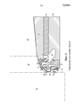
На фиг. 1 показан известный гидростатический подшипник в сборе, содержащий валок 10, имеющий концевую поверхность 12 и конусообразную секцию 14 шейки, ведущую к уменьшенному конусообразному диаметру 16, окруженному муфтой 18. Муфта 18 прикреплена к валку 10 посредством шпонки или другого устройства (не показано) для вращения вместе с втулкой 20, содержащейся в опорном подшипнике 22 валка или закрепленной относительно него.In FIG. 1 shows a known hydrostatic bearing assembly comprising a
Гибкое уплотнение 24 шейки установлено на конусообразной секции 14 валка для вращения с ней. Уплотнение 24 имеет круглое тело и удерживается на месте между муфтой 18 и конусообразной секцией 14 валка.A
Внутренний и наружный фланцы 26, 28 выступают радиально наружу из тела уплотнения. В контексте настоящего документа термин "внутренний" означает компонент, ближайший к концевой поверхности 12 валка, и термин "наружный" означает компонент, ближайший к втулке 6 и подшипнику 22. Отражатель 30 выступает под углом в сторону подшипника 22.The inner and
Внутренний и наружный фланцы 26, 28 имеют направленные в противоположные стороны манжетные уплотнения, выполненные с возможностью соприкосновения с окружными внутренней и наружной уплотнительными поверхностями 32, 34 концевой уплотнительной пластины 36. Концевая уплотнительная пластина прикреплена к подшипнику 22 и взаимодействует с ним для создания маслосборника 38. Окружные уплотнительные поверхности 32, 34 концевой уплотнительной пластины 36 разделены выступающим вовнутрь круглым фланцем 37, выполняющим функцию механической дамбы. Внутреннее кольцо 40 уплотнения и маслоотражательный щиток 42 завершают узел уплотнения.The inner and
Во время работы валок 10, уплотнение 24 шейки, внутреннее кольцо 40 уплотнения и муфта 18 вращаются вместе, тогда как втулка 20, подшипник 22, концевая уплотнительная пластина 36 и маслоотражательный щиток 42 остаются неподвижными. Масло подается между муфтой 18 и втулкой 20. Это масло принимает форму тонкой смазывающей пленки в зоне нагрузки подшипника перед выходом между муфтой 18 и втулкой 20 для собирания в маслосборнике 38.During operation, the
Отражатель 30 и наружный фланец 28 предназначены для удерживания масла в подшипнике, тогда как маслоотражательный щиток 42, внутреннее уплотнительное кольцо 40 и внутренний фланец 26 предназначены для исключения вхождения в подшипник внешних загрязнителей.The
Краткое изложение сущности изобретенияSummary of the invention
Вкратце аспекты настоящего изобретения относятся к улучшенному узлу уплотнения и уплотнению шейки. В соответствии с иллюстративными вариантами осуществления и при сравнении с обычным уплотнением и уплотнительным устройством, показанным на фиг. 1, уплотнение и концевая уплотнительная пластина настоящего изобретения имеют уменьшенную ширину, посредством этого позволяя либо увеличить ширину бочки валка, либо использовать альтернативные геометрии подшипника в этой же опоре валка для улучшения несущей способности опоры валка.Briefly, aspects of the present invention relate to an improved seal assembly and neck seal. In accordance with exemplary embodiments and when compared with the conventional seal and sealing device shown in FIG. 1, the seal and the end sealing plate of the present invention have a reduced width, thereby allowing either to increase the width of the roll barrel or to use alternative bearing geometries in the same roll support to improve the bearing capacity of the roll support.
Уменьшение ширины уплотнения и концевой уплотнительной пластины возможно посредством исключения фланца 37 обычной уплотнительной пластины и предусмотрения ступенчатой внутренней части, образующей внутреннюю и наружную уплотнительные поверхности, причем наружная уплотнительная поверхность имеет больший диаметр, чем диаметр внутренней уплотнительной поверхности, и обе уплотнительные поверхности соединены посредством кольцевой подпорной поверхности. Уплотнение соответственно переделано для предусмотрения наружного уплотнительного фланца, имеющего больший наружный диаметр, чем наружный диаметр внутреннего уплотнительного фланца.Reducing the width of the seal and the end sealing plate is possible by eliminating the
Краткое описание чертежейBrief Description of the Drawings
Эти и другие признаки и преимущества настоящего изобретения описаны далее более подробно со ссылкой на прилагаемые чертежи, в которых:These and other features and advantages of the present invention are described in more detail below with reference to the accompanying drawings, in which:
фиг. 1 представляет собой вид в частичном разрезе обычного гидростатического подшипника в сборе; иFIG. 1 is a partial sectional view of a conventional hydrostatic bearing assembly; and
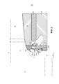
фиг. 2 представляет собой вид в частичном разрезе гидростатического подшипника в сборе и уплотнения согласно иллюстративным вариантам осуществления настоящего изобретения.FIG. 2 is a partial cross-sectional view of a hydrostatic bearing assembly and seal according to exemplary embodiments of the present invention.
Подробное описание вариантов осуществления настоящего изобретенияDetailed Description of Embodiments of the Present Invention
Для облегчения понимания вариантов осуществления, принципов и признаков настоящего изобретения они объяснены далее в этом документе со ссылкой на выполнение в иллюстративных вариантах осуществления. В частности, они описаны в контексте узла уплотнения и уплотнения шейки для гидростатического подшипника в прокатном стане.To facilitate understanding of the embodiments, principles and features of the present invention, they are explained later in this document with reference to the implementation in illustrative embodiments. In particular, they are described in the context of a seal assembly and a neck seal for a hydrostatic bearing in a rolling mill.
Компоненты и материалы, описанные далее в этом документе как составляющие различные варианты осуществления, являются иллюстративными и не являются ограничивающими. В объем вариантов осуществления настоящего изобретения включено множество подходящих компонентов и материалов, которые могут осуществлять функции, такие же или подобные функциям материалов и компонентов, описанных в этом документе.The components and materials described later in this document as constituting various embodiments are illustrative and not restrictive. In the scope of embodiments of the present invention included many suitable components and materials that can perform functions that are the same or similar to the functions of the materials and components described herein.
На фиг. 2 показаны гидростатический подшипник в сборе и уплотнение шейки согласно иллюстративным вариантам осуществления настоящего изобретения. Концевая уплотнительная пластина 36a теперь имеет ступенчатую внутреннюю часть, образующую внутреннюю и наружную окружные уплотнительные поверхности 32a, 34a, соединенные кольцевой подпорной поверхностью 37a. Диаметр наружной уплотнительной поверхности 34a больше, чем диаметр внутренней уплотнительной поверхности 32a. Обе уплотнительные поверхности 32a, 32b предпочтительно параллельны оси "A" вращения валка 10, причем подпорная поверхность 37a предпочтительно перпендикулярна оси A.In FIG. 2 shows a hydrostatic bearing assembly and a neck seal in accordance with illustrative embodiments of the present invention. The
Уплотнение 24a шейки теперь соответственно выполнено с наружным диаметром наружного фланца 28a, который больше, чем наружный диаметр внутреннего фланца 26a.The
Эти переделанные геометрии уплотнения 24a шейки и концевой уплотнительной пластины 36a позволяют исключить фланец 37 обычной концевой уплотнительной пластины 36, что, в свою очередь, позволяет преимущественно уменьшить ширину как уплотнения шейки, так и концевой уплотнительной пластины.These redone geometries of the
Это устройство имеет множество преимуществ. В качестве примера и не в качестве ограничения и без какого-либо конкретного порядка, во-первых, уменьшенная ширина уплотнения шейки и концевой уплотнительной пластины обеспечивает возможность увеличения ширины валка 10 (обозначенной "L" на фиг. 2) в той же опоре прокатного стана с преимуществами, очевидными для пользователя прокатного стана. Во-вторых, в качестве альтернативы может быть сохранена стандартная ширина валка с уменьшением ширины уплотнения и концевой уплотнительной пластины, используемым для альтернативных геометрий подшипника в той же опоре прокатного стана, разработанной для улучшения несущей способности опоры валка. В-третьих, переделанный узел уплотнения упрощает изготовление и сборку компонентов уплотнения.This device has many advantages. As an example and not by way of limitation and without any specific order, firstly, the reduced width of the neck seal and the end sealing plate makes it possible to increase the width of the roll 10 (indicated by "L" in Fig. 2) in the same support of the rolling mill with benefits that are obvious to the user of the rolling mill. Secondly, as an alternative, the standard roll width can be maintained with decreasing seal width and end sealing plate used for alternative bearing geometries in the same support of the rolling mill, designed to improve the bearing capacity of the roll support. Third, a redesigned seal assembly simplifies the manufacture and assembly of seal components.
Несмотря на то, что варианты осуществления настоящего изобретения описаны в иллюстративных формах, специалистам в данной области техники будет понятно, что множество модификаций, дополнений и исключений настоящего изобретения может быть выполнено без отхода от сущности и объема изобретения и его эквивалентов, как изложено в прилагаемой формуле изобретения.Although embodiments of the present invention are described in illustrative forms, those skilled in the art will understand that many modifications, additions and exceptions to the present invention can be made without departing from the spirit and scope of the invention and its equivalents, as set forth in the accompanying claims inventions.
Claims (5)
Applications Claiming Priority (3)
| Application Number | Priority Date | Filing Date | Title |
|---|---|---|---|
| US201361756506P | 2013-01-25 | 2013-01-25 | |
| US61/756,506 | 2013-01-25 | ||
| PCT/US2014/012168 WO2014116531A1 (en) | 2013-01-25 | 2014-01-20 | Seal assembly and neck seal for rolling mill |
Publications (2)
| Publication Number | Publication Date |
|---|---|
| RU2015135821A RU2015135821A (en) | 2017-03-02 |
| RU2657260C2 true RU2657260C2 (en) | 2018-06-09 |
Family
ID=50064796
Family Applications (1)
| Application Number | Title | Priority Date | Filing Date |
|---|---|---|---|
| RU2015135821A RU2657260C2 (en) | 2013-01-25 | 2014-01-20 | Seal assembly and neck seal for rolling mill |
Country Status (12)
| Country | Link |
|---|---|
| US (1) | US20160236250A1 (en) |
| EP (1) | EP2948258B1 (en) |
| JP (1) | JP6407169B2 (en) |
| KR (1) | KR102185262B1 (en) |
| CN (1) | CN104918721B (en) |
| BR (1) | BR112015017164B1 (en) |
| CA (1) | CA2899171C (en) |
| ES (1) | ES2672302T3 (en) |
| PL (1) | PL2948258T3 (en) |
| RU (1) | RU2657260C2 (en) |
| TW (1) | TWI632961B (en) |
| WO (1) | WO2014116531A1 (en) |
Families Citing this family (3)
| Publication number | Priority date | Publication date | Assignee | Title |
|---|---|---|---|---|
| CN109710964B (en) * | 2018-11-07 | 2020-11-10 | 西安交通大学 | Method for designing radial oil film bearing of rolling mill |
| US11008275B2 (en) * | 2019-06-12 | 2021-05-18 | Evonik Operations Gmbh | Process for preparing carboxylic acids or salts thereof from hydrocarbons |
| CN113418006B (en) * | 2021-06-21 | 2023-02-28 | 太原重工股份有限公司 | Reverse waterproof device of oil film bearing |
Citations (4)
| Publication number | Priority date | Publication date | Assignee | Title |
|---|---|---|---|---|
| US2860931A (en) * | 1956-09-11 | 1958-11-18 | Aluminum Co Of America | Roll neck bearing seals |
| WO2003078085A1 (en) * | 2002-03-15 | 2003-09-25 | Sms Demag Aktiengesellschaft | Sealing device comprising a two-piece annular body |
| RU2262402C1 (en) * | 2003-01-31 | 2005-10-20 | Морган Констракшн Компани | Packing unit of roll journal |
| RU2391158C1 (en) * | 2007-01-29 | 2010-06-10 | Смс Зимаг Аг | Journal seal for bearing of roller |
Family Cites Families (9)
| Publication number | Priority date | Publication date | Assignee | Title |
|---|---|---|---|---|
| CA1064539A (en) * | 1976-07-15 | 1979-10-16 | Lowell S. Salter (Jr.) | Flexible seal and seal assembly |
| US4585236A (en) * | 1985-03-14 | 1986-04-29 | Morgan Construction Company | Double jointed coolant seal |
| US5478090A (en) * | 1993-06-16 | 1995-12-26 | Morgan Construction Company | Interlocked seal and sleeve for rolling mill oil film bearing |
| US5316392A (en) * | 1993-10-21 | 1994-05-31 | Morgan Construction Company | Coolant guard for rolling mill oil film bearing assembly |
| US6146020A (en) * | 1999-02-26 | 2000-11-14 | Morgan Construction Company | Seal assembly for rolling mill oil film bearing |
| US20050184469A1 (en) * | 2004-02-20 | 2005-08-25 | Kazuo Ishii | Bearing seal |
| US7467796B2 (en) * | 2004-08-12 | 2008-12-23 | Morgan Construction, Company | Bearing seal with flexible lip |
| US8500332B2 (en) * | 2010-05-05 | 2013-08-06 | Siemens Industry, Inc. | Self pumping oil film bearing |
| US20110278801A1 (en) * | 2010-05-11 | 2011-11-17 | Morgan Construction Company | Neck seal |
-
2014
- 2014-01-20 JP JP2015555202A patent/JP6407169B2/en not_active Expired - Fee Related
- 2014-01-20 BR BR112015017164-8A patent/BR112015017164B1/en active IP Right Grant
- 2014-01-20 EP EP14703011.8A patent/EP2948258B1/en active Active
- 2014-01-20 ES ES14703011.8T patent/ES2672302T3/en active Active
- 2014-01-20 CA CA2899171A patent/CA2899171C/en active Active
- 2014-01-20 WO PCT/US2014/012168 patent/WO2014116531A1/en active Application Filing
- 2014-01-20 PL PL14703011T patent/PL2948258T3/en unknown
- 2014-01-20 RU RU2015135821A patent/RU2657260C2/en active
- 2014-01-20 KR KR1020157015116A patent/KR102185262B1/en active IP Right Grant
- 2014-01-20 US US14/364,329 patent/US20160236250A1/en not_active Abandoned
- 2014-01-20 CN CN201480003956.5A patent/CN104918721B/en active Active
- 2014-01-25 TW TW103102924A patent/TWI632961B/en active
Patent Citations (4)
| Publication number | Priority date | Publication date | Assignee | Title |
|---|---|---|---|---|
| US2860931A (en) * | 1956-09-11 | 1958-11-18 | Aluminum Co Of America | Roll neck bearing seals |
| WO2003078085A1 (en) * | 2002-03-15 | 2003-09-25 | Sms Demag Aktiengesellschaft | Sealing device comprising a two-piece annular body |
| RU2262402C1 (en) * | 2003-01-31 | 2005-10-20 | Морган Констракшн Компани | Packing unit of roll journal |
| RU2391158C1 (en) * | 2007-01-29 | 2010-06-10 | Смс Зимаг Аг | Journal seal for bearing of roller |
Also Published As
| Publication number | Publication date |
|---|---|
| TWI632961B (en) | 2018-08-21 |
| CN104918721A (en) | 2015-09-16 |
| EP2948258A1 (en) | 2015-12-02 |
| JP6407169B2 (en) | 2018-10-17 |
| CN104918721B (en) | 2020-07-28 |
| EP2948258B1 (en) | 2018-03-07 |
| KR102185262B1 (en) | 2020-12-01 |
| BR112015017164A2 (en) | 2017-07-11 |
| TW201446352A (en) | 2014-12-16 |
| CA2899171A1 (en) | 2014-07-31 |
| JP2016504201A (en) | 2016-02-12 |
| BR112015017164B1 (en) | 2022-08-16 |
| CA2899171C (en) | 2021-02-02 |
| KR20150110478A (en) | 2015-10-02 |
| WO2014116531A1 (en) | 2014-07-31 |
| US20160236250A1 (en) | 2016-08-18 |
| PL2948258T3 (en) | 2018-07-31 |
| ES2672302T3 (en) | 2018-06-13 |
| RU2015135821A (en) | 2017-03-02 |
Similar Documents
| Publication | Publication Date | Title |
|---|---|---|
| US9925830B2 (en) | Bearing rolling including a low friction sealing device, in particular for a hub bearing unit | |
| RU2657260C2 (en) | Seal assembly and neck seal for rolling mill | |
| US8955849B2 (en) | Radial shaft seal and assembly therewith | |
| AU2016304974A1 (en) | Sealing structure for bearing | |
| RU2012153344A (en) | NOZZLE SEAL FOR A HYDROSTATIC BEARING OF A ROLLING STATION WITH VOILERS LOCATED FROM ANOTHER FROM ANOTHER FOR OIL COMING FROM THE SUPPORT BUSHING AND BEARING INSIDE | |
| WO2009060715A1 (en) | Bearing for alternator | |
| JP2016504201A5 (en) | ||
| EP3184865B1 (en) | Sealing structure | |
| JP2015206441A (en) | sealing device | |
| CN103277519A (en) | Double-framework floating lip oil seal | |
| US10955005B2 (en) | Cardan universal joint seal with radially extending lips | |
| CN103629246B (en) | Double sealed bearing | |
| RU2017109819A (en) | RADIAL MOBILE SEALING | |
| ITUB20159812A1 (en) | ? IMPROVED ROLLINA? | |
| JP2018080741A5 (en) | ||
| CN205689596U (en) | Low-torque taper roll bearing | |
| JP2011058524A (en) | Rotary shaft seal structure of transmission device for automobile | |
| JP2013160280A (en) | Sealed rolling bearing | |
| CN100413609C (en) | Sealing device for cylinder bearings | |
| CN203702886U (en) | Bearing unit with rotational speed detection device | |
| WO2015166883A1 (en) | Tapered roller bearing | |
| JP2019060441A (en) | Ball bearing with seal | |
| CN211082782U (en) | Oil seal of motor reducer assembly and motor reducer assembly with same | |
| CN109958719A (en) | Bearing with contact type sealing structure | |
| JP2015215062A (en) | Sealing device |
Legal Events
| Date | Code | Title | Description |
|---|---|---|---|
| HC9A | Changing information about inventors |