RU2656657C2 - Composite layer materials containing the pattern of holes produced by controlled fiber placement - Google Patents
Composite layer materials containing the pattern of holes produced by controlled fiber placement Download PDFInfo
- Publication number
- RU2656657C2 RU2656657C2 RU2015149039A RU2015149039A RU2656657C2 RU 2656657 C2 RU2656657 C2 RU 2656657C2 RU 2015149039 A RU2015149039 A RU 2015149039A RU 2015149039 A RU2015149039 A RU 2015149039A RU 2656657 C2 RU2656657 C2 RU 2656657C2
- Authority
- RU
- Russia
- Prior art keywords
- layers
- holes
- laying
- fibers
- bundles
- Prior art date
Links
Images

Classifications
-
- B—PERFORMING OPERATIONS; TRANSPORTING
- B32—LAYERED PRODUCTS
- B32B—LAYERED PRODUCTS, i.e. PRODUCTS BUILT-UP OF STRATA OF FLAT OR NON-FLAT, e.g. CELLULAR OR HONEYCOMB, FORM
- B32B5/00—Layered products characterised by the non- homogeneity or physical structure, i.e. comprising a fibrous, filamentary, particulate or foam layer; Layered products characterised by having a layer differing constitutionally or physically in different parts
- B32B5/02—Layered products characterised by the non- homogeneity or physical structure, i.e. comprising a fibrous, filamentary, particulate or foam layer; Layered products characterised by having a layer differing constitutionally or physically in different parts characterised by structural features of a fibrous or filamentary layer
- B32B5/024—Woven fabric
-
- B—PERFORMING OPERATIONS; TRANSPORTING
- B29—WORKING OF PLASTICS; WORKING OF SUBSTANCES IN A PLASTIC STATE IN GENERAL
- B29C—SHAPING OR JOINING OF PLASTICS; SHAPING OF MATERIAL IN A PLASTIC STATE, NOT OTHERWISE PROVIDED FOR; AFTER-TREATMENT OF THE SHAPED PRODUCTS, e.g. REPAIRING
- B29C70/00—Shaping composites, i.e. plastics material comprising reinforcements, fillers or preformed parts, e.g. inserts
- B29C70/04—Shaping composites, i.e. plastics material comprising reinforcements, fillers or preformed parts, e.g. inserts comprising reinforcements only, e.g. self-reinforcing plastics
- B29C70/06—Fibrous reinforcements only
- B29C70/10—Fibrous reinforcements only characterised by the structure of fibrous reinforcements, e.g. hollow fibres
- B29C70/16—Fibrous reinforcements only characterised by the structure of fibrous reinforcements, e.g. hollow fibres using fibres of substantial or continuous length
- B29C70/22—Fibrous reinforcements only characterised by the structure of fibrous reinforcements, e.g. hollow fibres using fibres of substantial or continuous length oriented in at least two directions forming a two dimensional structure
- B29C70/224—Fibrous reinforcements only characterised by the structure of fibrous reinforcements, e.g. hollow fibres using fibres of substantial or continuous length oriented in at least two directions forming a two dimensional structure the structure being a net
-
- B—PERFORMING OPERATIONS; TRANSPORTING
- B29—WORKING OF PLASTICS; WORKING OF SUBSTANCES IN A PLASTIC STATE IN GENERAL
- B29C—SHAPING OR JOINING OF PLASTICS; SHAPING OF MATERIAL IN A PLASTIC STATE, NOT OTHERWISE PROVIDED FOR; AFTER-TREATMENT OF THE SHAPED PRODUCTS, e.g. REPAIRING
- B29C70/00—Shaping composites, i.e. plastics material comprising reinforcements, fillers or preformed parts, e.g. inserts
- B29C70/04—Shaping composites, i.e. plastics material comprising reinforcements, fillers or preformed parts, e.g. inserts comprising reinforcements only, e.g. self-reinforcing plastics
- B29C70/28—Shaping operations therefor
- B29C70/30—Shaping by lay-up, i.e. applying fibres, tape or broadsheet on a mould, former or core; Shaping by spray-up, i.e. spraying of fibres on a mould, former or core
- B29C70/38—Automated lay-up, e.g. using robots, laying filaments according to predetermined patterns
- B29C70/386—Automated tape laying [ATL]
-
- B—PERFORMING OPERATIONS; TRANSPORTING
- B32—LAYERED PRODUCTS
- B32B—LAYERED PRODUCTS, i.e. PRODUCTS BUILT-UP OF STRATA OF FLAT OR NON-FLAT, e.g. CELLULAR OR HONEYCOMB, FORM
- B32B3/00—Layered products comprising a layer with external or internal discontinuities or unevennesses, or a layer of non-planar form; Layered products having particular features of form
- B32B3/02—Layered products comprising a layer with external or internal discontinuities or unevennesses, or a layer of non-planar form; Layered products having particular features of form characterised by features of form at particular places, e.g. in edge regions
-
- B—PERFORMING OPERATIONS; TRANSPORTING
- B32—LAYERED PRODUCTS
- B32B—LAYERED PRODUCTS, i.e. PRODUCTS BUILT-UP OF STRATA OF FLAT OR NON-FLAT, e.g. CELLULAR OR HONEYCOMB, FORM
- B32B3/00—Layered products comprising a layer with external or internal discontinuities or unevennesses, or a layer of non-planar form; Layered products having particular features of form
- B32B3/10—Layered products comprising a layer with external or internal discontinuities or unevennesses, or a layer of non-planar form; Layered products having particular features of form characterised by a discontinuous layer, i.e. formed of separate pieces of material
- B32B3/12—Layered products comprising a layer with external or internal discontinuities or unevennesses, or a layer of non-planar form; Layered products having particular features of form characterised by a discontinuous layer, i.e. formed of separate pieces of material characterised by a layer of regularly- arranged cells, e.g. a honeycomb structure
-
- B—PERFORMING OPERATIONS; TRANSPORTING
- B32—LAYERED PRODUCTS
- B32B—LAYERED PRODUCTS, i.e. PRODUCTS BUILT-UP OF STRATA OF FLAT OR NON-FLAT, e.g. CELLULAR OR HONEYCOMB, FORM
- B32B3/00—Layered products comprising a layer with external or internal discontinuities or unevennesses, or a layer of non-planar form; Layered products having particular features of form
- B32B3/26—Layered products comprising a layer with external or internal discontinuities or unevennesses, or a layer of non-planar form; Layered products having particular features of form characterised by a particular shape of the outline of the cross-section of a continuous layer; characterised by a layer with cavities or internal voids ; characterised by an apertured layer
- B32B3/266—Layered products comprising a layer with external or internal discontinuities or unevennesses, or a layer of non-planar form; Layered products having particular features of form characterised by a particular shape of the outline of the cross-section of a continuous layer; characterised by a layer with cavities or internal voids ; characterised by an apertured layer characterised by an apertured layer, the apertures going through the whole thickness of the layer, e.g. expanded metal, perforated layer, slit layer regular cells B32B3/12
-
- B—PERFORMING OPERATIONS; TRANSPORTING
- B32—LAYERED PRODUCTS
- B32B—LAYERED PRODUCTS, i.e. PRODUCTS BUILT-UP OF STRATA OF FLAT OR NON-FLAT, e.g. CELLULAR OR HONEYCOMB, FORM
- B32B5/00—Layered products characterised by the non- homogeneity or physical structure, i.e. comprising a fibrous, filamentary, particulate or foam layer; Layered products characterised by having a layer differing constitutionally or physically in different parts
- B32B5/02—Layered products characterised by the non- homogeneity or physical structure, i.e. comprising a fibrous, filamentary, particulate or foam layer; Layered products characterised by having a layer differing constitutionally or physically in different parts characterised by structural features of a fibrous or filamentary layer
- B32B5/022—Non-woven fabric
-
- B—PERFORMING OPERATIONS; TRANSPORTING
- B32—LAYERED PRODUCTS
- B32B—LAYERED PRODUCTS, i.e. PRODUCTS BUILT-UP OF STRATA OF FLAT OR NON-FLAT, e.g. CELLULAR OR HONEYCOMB, FORM
- B32B5/00—Layered products characterised by the non- homogeneity or physical structure, i.e. comprising a fibrous, filamentary, particulate or foam layer; Layered products characterised by having a layer differing constitutionally or physically in different parts
- B32B5/02—Layered products characterised by the non- homogeneity or physical structure, i.e. comprising a fibrous, filamentary, particulate or foam layer; Layered products characterised by having a layer differing constitutionally or physically in different parts characterised by structural features of a fibrous or filamentary layer
- B32B5/12—Layered products characterised by the non- homogeneity or physical structure, i.e. comprising a fibrous, filamentary, particulate or foam layer; Layered products characterised by having a layer differing constitutionally or physically in different parts characterised by structural features of a fibrous or filamentary layer characterised by the relative arrangement of fibres or filaments of different layers, e.g. the fibres or filaments being parallel or perpendicular to each other
-
- B—PERFORMING OPERATIONS; TRANSPORTING
- B32—LAYERED PRODUCTS
- B32B—LAYERED PRODUCTS, i.e. PRODUCTS BUILT-UP OF STRATA OF FLAT OR NON-FLAT, e.g. CELLULAR OR HONEYCOMB, FORM
- B32B5/00—Layered products characterised by the non- homogeneity or physical structure, i.e. comprising a fibrous, filamentary, particulate or foam layer; Layered products characterised by having a layer differing constitutionally or physically in different parts
- B32B5/22—Layered products characterised by the non- homogeneity or physical structure, i.e. comprising a fibrous, filamentary, particulate or foam layer; Layered products characterised by having a layer differing constitutionally or physically in different parts characterised by the presence of two or more layers which are next to each other and are fibrous, filamentary, formed of particles or foamed
- B32B5/24—Layered products characterised by the non- homogeneity or physical structure, i.e. comprising a fibrous, filamentary, particulate or foam layer; Layered products characterised by having a layer differing constitutionally or physically in different parts characterised by the presence of two or more layers which are next to each other and are fibrous, filamentary, formed of particles or foamed one layer being a fibrous or filamentary layer
- B32B5/26—Layered products characterised by the non- homogeneity or physical structure, i.e. comprising a fibrous, filamentary, particulate or foam layer; Layered products characterised by having a layer differing constitutionally or physically in different parts characterised by the presence of two or more layers which are next to each other and are fibrous, filamentary, formed of particles or foamed one layer being a fibrous or filamentary layer another layer next to it also being fibrous or filamentary
-
- B—PERFORMING OPERATIONS; TRANSPORTING
- B32—LAYERED PRODUCTS
- B32B—LAYERED PRODUCTS, i.e. PRODUCTS BUILT-UP OF STRATA OF FLAT OR NON-FLAT, e.g. CELLULAR OR HONEYCOMB, FORM
- B32B5/00—Layered products characterised by the non- homogeneity or physical structure, i.e. comprising a fibrous, filamentary, particulate or foam layer; Layered products characterised by having a layer differing constitutionally or physically in different parts
- B32B5/22—Layered products characterised by the non- homogeneity or physical structure, i.e. comprising a fibrous, filamentary, particulate or foam layer; Layered products characterised by having a layer differing constitutionally or physically in different parts characterised by the presence of two or more layers which are next to each other and are fibrous, filamentary, formed of particles or foamed
- B32B5/24—Layered products characterised by the non- homogeneity or physical structure, i.e. comprising a fibrous, filamentary, particulate or foam layer; Layered products characterised by having a layer differing constitutionally or physically in different parts characterised by the presence of two or more layers which are next to each other and are fibrous, filamentary, formed of particles or foamed one layer being a fibrous or filamentary layer
- B32B5/28—Layered products characterised by the non- homogeneity or physical structure, i.e. comprising a fibrous, filamentary, particulate or foam layer; Layered products characterised by having a layer differing constitutionally or physically in different parts characterised by the presence of two or more layers which are next to each other and are fibrous, filamentary, formed of particles or foamed one layer being a fibrous or filamentary layer impregnated with or embedded in a plastic substance
-
- B—PERFORMING OPERATIONS; TRANSPORTING
- B32—LAYERED PRODUCTS
- B32B—LAYERED PRODUCTS, i.e. PRODUCTS BUILT-UP OF STRATA OF FLAT OR NON-FLAT, e.g. CELLULAR OR HONEYCOMB, FORM
- B32B2260/00—Layered product comprising an impregnated, embedded, or bonded layer wherein the layer comprises an impregnation, embedding, or binder material
- B32B2260/02—Composition of the impregnated, bonded or embedded layer
- B32B2260/021—Fibrous or filamentary layer
- B32B2260/023—Two or more layers
-
- B—PERFORMING OPERATIONS; TRANSPORTING
- B32—LAYERED PRODUCTS
- B32B—LAYERED PRODUCTS, i.e. PRODUCTS BUILT-UP OF STRATA OF FLAT OR NON-FLAT, e.g. CELLULAR OR HONEYCOMB, FORM
- B32B2260/00—Layered product comprising an impregnated, embedded, or bonded layer wherein the layer comprises an impregnation, embedding, or binder material
- B32B2260/04—Impregnation, embedding, or binder material
- B32B2260/046—Synthetic resin
-
- B—PERFORMING OPERATIONS; TRANSPORTING
- B32—LAYERED PRODUCTS
- B32B—LAYERED PRODUCTS, i.e. PRODUCTS BUILT-UP OF STRATA OF FLAT OR NON-FLAT, e.g. CELLULAR OR HONEYCOMB, FORM
- B32B2262/00—Composition or structural features of fibres which form a fibrous or filamentary layer or are present as additives
- B32B2262/10—Inorganic fibres
- B32B2262/106—Carbon fibres, e.g. graphite fibres
-
- B—PERFORMING OPERATIONS; TRANSPORTING
- B32—LAYERED PRODUCTS
- B32B—LAYERED PRODUCTS, i.e. PRODUCTS BUILT-UP OF STRATA OF FLAT OR NON-FLAT, e.g. CELLULAR OR HONEYCOMB, FORM
- B32B2305/00—Condition, form or state of the layers or laminate
- B32B2305/02—Cellular or porous
- B32B2305/024—Honeycomb
-
- B—PERFORMING OPERATIONS; TRANSPORTING
- B32—LAYERED PRODUCTS
- B32B—LAYERED PRODUCTS, i.e. PRODUCTS BUILT-UP OF STRATA OF FLAT OR NON-FLAT, e.g. CELLULAR OR HONEYCOMB, FORM
- B32B2307/00—Properties of the layers or laminate
- B32B2307/10—Properties of the layers or laminate having particular acoustical properties
- B32B2307/102—Insulating
-
- B—PERFORMING OPERATIONS; TRANSPORTING
- B32—LAYERED PRODUCTS
- B32B—LAYERED PRODUCTS, i.e. PRODUCTS BUILT-UP OF STRATA OF FLAT OR NON-FLAT, e.g. CELLULAR OR HONEYCOMB, FORM
- B32B2605/00—Vehicles
-
- Y—GENERAL TAGGING OF NEW TECHNOLOGICAL DEVELOPMENTS; GENERAL TAGGING OF CROSS-SECTIONAL TECHNOLOGIES SPANNING OVER SEVERAL SECTIONS OF THE IPC; TECHNICAL SUBJECTS COVERED BY FORMER USPC CROSS-REFERENCE ART COLLECTIONS [XRACs] AND DIGESTS
- Y10—TECHNICAL SUBJECTS COVERED BY FORMER USPC
- Y10T—TECHNICAL SUBJECTS COVERED BY FORMER US CLASSIFICATION
- Y10T428/00—Stock material or miscellaneous articles
- Y10T428/24—Structurally defined web or sheet [e.g., overall dimension, etc.]
- Y10T428/24058—Structurally defined web or sheet [e.g., overall dimension, etc.] including grain, strips, or filamentary elements in respective layers or components in angular relation
- Y10T428/24074—Strand or strand-portions
Abstract
Description
ОБЩАЯ ИНФОРМАЦИЯGENERAL INFORMATION
1. Область техники:1. Field of technology:
Настоящее описание в целом относится к способам изготовления композиционных слоистых материалов и, более конкретно, относится к способу получения систем отверстий в указанных слоистых материалах с применением регулируемой выкладки волокон, а также к слоистым материалам, имеющим системы отверстий, полученным с помощью них.The present description generally relates to methods for manufacturing composite laminate materials and, more particularly, relates to a method for producing hole systems in said laminate materials using adjustable lay-out of fibers, as well as to layered materials having hole systems obtained using them.
2. Уровень техники:2. The level of technology:
В некоторых случаях в композиционном материале необходимо получить большое количество отверстий или перфораций. Например, в акустически обработанных конструкциях может быть использована акустическая панель, имеющая внешнюю листовую облицовку с тысячами отверстий. Отверстия в листовой облицовке вместе с ячеистой сердцевиной панели обеспечивают ослабление звука. Обшивка крыльев воздушных судов также может содержать композиционные слоистые наружные слои, которые перфорированы для изменения потока воздуха над крылом.In some cases, it is necessary to obtain a large number of holes or perforations in the composite material. For example, in acoustically treated structures, an acoustic panel having an external sheet cladding with thousands of holes can be used. The holes in the sheet cladding along with the cellular core of the panel provide sound attenuation. Aircraft wing sheathing may also contain composite layered outer layers that are perforated to change airflow over the wing.
Современные технологии формирования большого количества перфораций или отверстий в композиционном слоистом материале могут быть долгими, трудоемкими и дорогостоящими. В одной из технологий используют инструмент, называемый матом с шипами, для создания отверстий в отдельных слоях полотна, которые продавливают поверх и вокруг шипов, а затем отверждают с получением слоистого материала. Шипы могут быть хрупкими и с трудом поддающимися удалению из отвержденного слоистого материала. В другой технологии отверстия формируют высверливанием отдельных отверстий в слоистом материале после его отверждения. Сверление тысяч отдельных отверстий с помощью сверла занимает много времени и может приводить к разрушению волокон вокруг отверстий в результате износа сверла. Отверстия в композиционном слоистом материале также могут быть сформированы с применением комбинации нанесения маски и пескоструйной обработки, где систему отверстий маскируют на отвержденном слоистом материале, а отверстия выбивают в нем с помощью пескоструйной обработки. Процесс пескоструйной обработки также может приводить к нежелательному разрушению волокон. Разрушение волокон вокруг отверстия может обусловливать получение выходящего за пределы допусков диаметра отверстия, чистовой обработки отверстия и/или кромок отверстия.Modern technologies for the formation of a large number of perforations or holes in a composite laminate can be long, laborious, and expensive. One technology uses a tool called a spike mat to create holes in individual layers of the fabric that are pressed over and around the spikes and then cured to produce a layered material. The spikes can be brittle and difficult to remove from the cured laminate. In another technology, holes are formed by drilling individual holes in the laminate after it has cured. Drilling thousands of individual holes with a drill takes a lot of time and can lead to the destruction of fibers around the holes as a result of wear on the drill. Holes in the composite laminate can also be formed using a combination of masking and sandblasting, where the hole system is masked on the cured laminate and the holes are knocked out using sandblasting. The sandblasting process can also lead to undesirable destruction of the fibers. The destruction of the fibers around the hole can cause getting beyond the tolerances of the diameter of the hole, finishing the hole and / or the edges of the hole.
Соответственно, существует потребность в способе формирования относительно большого количества отверстий или перфораций в композиционном слоистом материале, который является простым, эффективным и контролируемым, и который исключает необходимость в процессах механической обработки и/или сверления. Существует также потребность в способе формирования систем отверстий in situ в слоистой структуре по мере изготовления слоистого материала. Кроме того, существует потребность в перфорированном композиционном слоистом материале, имеющем регулируемую систему отверстий, где сформированные отверстия могут иметь различный размер, форму и схему расположения.Accordingly, there is a need for a method of forming a relatively large number of holes or perforations in a composite laminate that is simple, efficient and controllable, and which eliminates the need for machining and / or drilling processes. There is also a need for a method of forming in situ hole systems in a layered structure as the layered material is manufactured. In addition, there is a need for a perforated composite laminate having an adjustable hole system, where the formed holes can have a different size, shape and layout.
КРАТКОЕ ОПИСАНИЕSHORT DESCRIPTION
В описанных вариантах реализации предложен способ формирования системы отверстий в композиционном слоистом материале, таком как обшивка, используемая в акустически обработанных панелях для шумоподавления. Системы отверстий могут быть сформированы в слоистой структуре in situ по мере создания слоистого материала. Исключена потребность в специализированном оборудовании, таком как мат с шипами, а также в процессах, таких как сверление и пескоструйная обработка, которые могут приводить к разрушению волокон. Указанный способ может быть осуществлен с помощью оборудования для автоматической выкладки волокон с цифровым управлением и, следовательно, является эффективным, в высокой степени воспроизводимым и подходящим для применения при высоких скоростях производства. Указанный способ также хорошо подходит для применения при изготовлении композиционных слоистых материалов с регулируемой системой отверстий с использованием безавтоклавных процессов. Для улучшения звукопоглощающих свойств слоистого материала, в процессе формирования системы отверстий в слоистый материал могут быть включены тканые или нетканые материалы, такие как, без ограничения, металлические или пластмассовые проволочные сетки.In the described embodiments, there is provided a method of forming a system of holes in a composite laminate, such as skin, used in acoustically processed noise reduction panels. Hole systems can be formed in situ in a layered structure as the layered material is created. Eliminated the need for specialized equipment, such as a spike mat, as well as processes, such as drilling and sandblasting, which can lead to the destruction of fibers. The specified method can be implemented using equipment for the automatic laying of fibers with digital control and, therefore, is effective, highly reproducible and suitable for use at high production speeds. The specified method is also well suited for use in the manufacture of composite layered materials with an adjustable hole system using autoclave-free processes. To improve the sound-absorbing properties of the laminate, woven or non-woven materials, such as, without limitation, metal or plastic wire mesh, can be incorporated into the laminate during the formation of the hole system.
В соответствии с одним из описанных вариантов реализации предложен способ получения композиционного слоистого материала, содержащего систему отверстий. Указанный способ включает формирование пакета слоев посредством выкладки друг на друга нескольких слоев смолы, армированной однонаправленными волокнами («препрег»), где каждый из слоев имеет определенную ориентацию волокон и содержит множество жгутов из армированной волокнами смолы с зазорами между ними. Ориентацию волокон в слоях пакета слоев варьируют с получением системы отверстий в композиционном слоистом материале. Указанный способ может дополнительно включать регулирование зазоров между жгутами в каждом слое, а также варьирование ширины жгутов. Выкладку множества слоев выполняют автоматически с помощью устройства для выкладки волокон с цифровым управлением. Указанный способ также может включать внедрение по меньшей мере одного тканого или нетканого материала в указанное множество слоев. Указанный способ может дополнительно включать выбор системы отверстий и программирование автоматического устройства для выкладки волокон для автоматической выкладки слоев друг на друга, а также для изменения ориентации волокон в слоях для формирования выбранной системы отверстий. Указанный способ может включать выбор размера и формы отверстий и программирование автоматического устройства для выкладки волокон для автоматической выкладки слоев друг на друга, а также для изменения ориентации волокон в слоях для формирования отверстий, имеющих выбранные размер и форму. Указанный способ может дополнительно включать отверждение пакета слоев и выбор смолы, обладающей контролируемыми характеристиками течения, которые по существу препятствуют заполнению отверстий смолой при отверждении. Пакет слоев может быть отвержден с применением безавтоклавного процесса, в котором используют вакуумное давление для облегчения регулирования потока смолы, хотя возможно также автоклавное отверждение.In accordance with one of the described embodiments, a method for producing a composite laminate containing a system of holes is provided. The specified method includes forming a packet of layers by laying on each other several layers of resin reinforced with unidirectional fibers (“prepreg”), where each of the layers has a specific orientation of the fibers and contains many bundles of fiber-reinforced resin with gaps between them. The orientation of the fibers in the layers of the stack of layers varies with obtaining a system of holes in the composite laminate. The specified method may further include adjusting the gaps between the bundles in each layer, as well as varying the width of the bundles. Layout of many layers is performed automatically using a device for laying fibers with digital control. The method may also include incorporating at least one woven or nonwoven material into the plurality of layers. The specified method may further include selecting a system of holes and programming an automatic device for laying out fibers for automatically laying layers on top of each other, as well as for changing the orientation of the fibers in the layers to form the selected system of holes. The specified method may include selecting the size and shape of the holes and programming an automatic device for laying fibers to automatically lay layers on top of each other, as well as changing the orientation of the fibers in the layers to form holes with the selected size and shape. The method may further include curing the stack of layers and selecting a resin having controlled flow characteristics that substantially impede the filling of the holes with the resin during curing. The stack of layers can be cured using a non-autoclave process that uses vacuum pressure to facilitate control of the resin flow, although autoclave curing is also possible.
В соответствии с другим описанным вариантом реализации предложен способ получения пакета слоев композиционного слоистого материала, содержащего систему отверстий. Пакет слоев формируют выкладкой друг на друга множества слоев препрега с однонаправленными волокнами, каждый из которых выкладывают посредством укладки полос волокнистых жгутов препрега. Указанный способ включает также раздвигание жгутов в каждой полосе на некоторое расстояние с получением зазоров между жгутами при укладке указанных полос, и регулирование положения жгутов при укладке полос. При укладке полос регулируют зазоры между жгутами, а ориентацию волокон в слоях варьируют с получением системы отверстий в пакете слоев. Каждый из слоев выкладывают с применением автоматического устройства для выкладки волокон с цифровым управлением. Раздвигание жгутов включает изменение зазоров между жгутами. Указанный способ может дополнительно включать изменение ширины жгутов. Между слоями в пакете слоев может быть расположен по меньшей мере один тканый или нетканый материал. Указанный способ также может включать выбор расположения отверстий, размера отверстий и формы отверстий, и программирование автоматического устройства для выкладки волокон для автоматической выкладки слоев друг на друга, а также для изменения ориентации волокон в слоях для формирования определенной системы отверстий. Указанный способ может дополнительно включать отверждение пакета слоев и выбор смолы, обладающей контролируемыми характеристиками течения, которые по существу препятствуют заполнению отверстий смолой при отверждении.In accordance with another described embodiment, a method for producing a stack of layers of a composite laminate containing a system of holes is provided. The package of layers is formed by laying on each other a plurality of layers of a prepreg with unidirectional fibers, each of which is laid out by laying strips of fiber bundles of the prepreg. The specified method also includes pushing the harnesses in each strip a certain distance to obtain gaps between the harnesses when laying said strips, and adjusting the position of the harnesses when laying strips. When laying strips, the gaps between the bundles are regulated, and the orientation of the fibers in the layers is varied to produce a system of holes in the packet of layers. Each of the layers is laid out using an automatic device for laying out fibers with digital control. Spreading the harnesses involves changing the gaps between the harnesses. The specified method may further include changing the width of the bundles. At least one woven or non-woven material may be located between the layers in the stack of layers. The method may also include selecting the location of the holes, the size of the holes and the shape of the holes, and programming an automatic device for laying fibers to automatically lay layers on top of each other, as well as for changing the orientation of the fibers in the layers to form a specific system of holes. The method may further include curing the stack of layers and selecting a resin having controlled flow characteristics that substantially impede the filling of the holes with the resin during curing.
В соответствии с другим вариантом реализации предложен композиционный слоистый материал, содержащий систему отверстий. Указанный слоистый материал содержит множество отстоящих друг от друга волокнистых жгутов, имеющих различную ориентацию волокон, расположенных так, чтобы образовывать систему отверстий в слоистом материале, а также смолистую матрицу, в которую включены волокнистые жгуты. Волокнистые жгуты расположены во множестве слоев, имеющих различную ориентацию волокон, и указанные волокнистые жгуты имеют разную ширину. Каждое отверстие может иметь многоугольную форму. Смолистая матрица может представлять собой термореактивный материал, отверждаемый термически, или термопластичный материал, и она обладает такими характеристиками течения, которые препятствуют затеканию материала в отверстия во время термического отверждения.According to another embodiment, a composite laminate comprising a system of holes is provided. The specified layered material contains many spaced apart fiber bundles having different orientations of the fibers, arranged so as to form a system of holes in the layered material, as well as a resinous matrix, which includes fiber bundles. The fiber tows are arranged in a plurality of layers having different fiber orientations, and said fiber tows have different widths. Each hole may have a polygonal shape. The resin matrix may be a thermosetting material, thermally curable, or a thermoplastic material, and it has such flow characteristics that prevent the material from flowing into holes during thermal curing.
В соответствии с другим вариантом реализации предложен пакет слоев композиционного слоистого материала, содержащий систему отверстий. Пакет слоев слоистого материала содержит множество слоев армированной волокнами смолы, где каждый из слоев имеет однонаправленные волокна и содержит множество жгутов препрега с зазорами между ними. Слои располагают так, чтобы зазоры между жгутами препрега образовывали систему отверстий в пакете слоев. Смола является термически отверждаемой и имеет при отверждении такие характеристики течения, которые препятствуют затеканию смолы в отверстия. Варьируют зазоры между жгутами препрега, и от слоя к слою варьируют ширину жгутов.In accordance with another implementation option proposed a package of layers of a composite laminate containing a system of holes. The stack of layers of the layered material contains many layers of fiber reinforced resin, where each of the layers has unidirectional fibers and contains many strands of prepreg with gaps between them. The layers are arranged so that the gaps between the prepreg strands form a system of holes in the layer stack. The resin is thermally curable and has, during curing, flow characteristics that prevent the resin from flowing into the holes. The gaps between the prepreg strands vary, and the width of the bundles varies from layer to layer.
Таким образом, в соответствии с одним аспектом настоящего изобретения предложен способ получения композиционного слоистого материала, имеющего систему отверстий, включающий формирование пакета слоев посредством выкладки множества слоев армированной волокнами смолы, каждый из которых имеет определенную ориентацию волокон и содержит множество жгутов из армированной волокнами смолы с зазорами между ними; и варьирование ориентации волокон в слоях пакета слоев с получением системы отверстий в композиционной слоистом материале.Thus, in accordance with one aspect of the present invention, there is provided a method for producing a composite laminate having an aperture system, comprising forming a stack of layers by laying out a plurality of layers of fiber reinforced resin, each of which has a specific fiber orientation and contains a plurality of fiber reinforced resin tows with gaps between them; and varying the orientation of the fibers in the layers of the packet of layers to obtain a system of holes in the composite laminate.
Преимущественно, указанный способ дополнительно включает регулирование зазоров между жгутами в каждом из слоев.Advantageously, said method further includes adjusting the gaps between the bundles in each of the layers.
Преимущественно, способ, в котором выполняют выкладку друг на друга множества слоев, включает применение жгутов, имеющих по меньшей мере две разные ширины, соответственно, в по меньшей мере двух из слоев.Advantageously, the method in which a plurality of layers are laid on each other includes the use of bundles having at least two different widths, respectively, in at least two of the layers.
Преимущественно, способ, в котором выполняют выкладку множества слоев, осуществляют автоматически с помощью устройства для выкладки волокон с цифровым управлением.Advantageously, the method in which a plurality of layers are laid out is carried out automatically using a digitally controlled fiber laying device.
Преимущественно, указанный способ дополнительно включает внедрение по меньшей мере одного тканого или нетканого материала в указанное множество слоев.Advantageously, said method further comprises incorporating at least one woven or non-woven material into said plurality of layers.
Преимущественно, указанный способ дополнительно включает выбор системы отверстий; и программирование автоматического устройства для выкладки волокон для автоматической выкладки друг на друга слоев с применением раздвинутых жгутов, а также для изменения ориентации волокон в слоях для формирования выбранной системы отверстий.Advantageously, said method further includes selecting a hole system; and programming an automatic device for laying out fibers to automatically lay out layers on top of each other using extended harnesses, as well as to change the orientation of the fibers in the layers to form the selected hole system.
Преимущественно, указанный способ дополнительно включает выбор размера и формы отверстий; и программирование автоматического устройства для выкладки волокон для автоматической выкладки слоев друг на друга, а также для изменения ориентации волокон в слоях для формирования отверстий, имеющих выбранные размер и форму.Advantageously, said method further includes selecting the size and shape of the holes; and programming an automatic device for laying out fibers for automatically laying out layers on top of each other, as well as for changing the orientation of the fibers in the layers to form holes of a selected size and shape.
Преимущественно, указанный способ дополнительно включает отверждение пакета слоев; и выбор смолы, обладающей контролируемыми характеристиками течения, которые по существу препятствуют заполнению отверстий смолой при отверждении.Advantageously, said method further includes curing the packet of layers; and selecting a resin having controlled flow characteristics that substantially impede the filling of the holes with the resin during curing.
Преимущественно, способ, в котором выполняют отверждение пакета слоев, осуществляют с применением безавтоклавного и автоклавного процесса отверждения.Advantageously, the method in which the package of layers is cured is carried out using a non-autoclave and autoclave curing process.
В соответствии с другим аспектом настоящего изобретения предложен способ получения пакета слоев композиционного слоистого материала, имеющего систему отверстий, включающий формирование пакета слоев посредством выкладки множества слоев однонаправленных волокон препрега, каждый из указанных слоев выкладывают посредством укладки полос волокнистых жгутов препрега; раздвигание жгутов в каждой полосе на некоторое расстояние друг от друга с получением зазоров между жгутами при укладке полос; регулирование положений жгутов при укладке полос; регулирование зазоров между жгутами при укладке полос; и изменение ориентации волокон в слоях с получением системы отверстий в пакете слоев.In accordance with another aspect of the present invention, there is provided a method for producing a stack of layers of a composite laminate having a system of holes, comprising forming a stack of layers by laying out a plurality of layers of unidirectional prepreg fibers, each of which is laid out by laying strips of fibrous prepreg strands; pushing the harnesses in each strip a certain distance from each other to obtain gaps between the harnesses when laying strips; regulation of the positions of the harnesses when laying strips; regulation of gaps between plaits when laying strips; and changing the orientation of the fibers in the layers to obtain a system of holes in the package of layers.
Преимущественно, указанный способ выкладки каждого из слоев выполняют с применением автоматического устройства для выкладки волокон с цифровым управлением.Advantageously, said method of laying out each of the layers is performed using an automatic digitally arranged fiber laying device.
Преимущественно, указанный способ, в котором выполняют раздвигание жгутов, включает изменение зазоров между жгутами.Advantageously, said method in which the extension of the strands is carried out involves changing the gaps between the strands.
Преимущественно, указанный способ дополнительно включает изменение ширины жгутов.Advantageously, said method further includes changing the width of the tows.
Преимущественно, указанный способ дополнительно включает внедрение по меньшей мере одного тканого или нетканого материала между слоями пакета слоев.Advantageously, said method further comprises incorporating at least one woven or nonwoven material between the layers of the stack of layers.
Преимущественно, указанный способ дополнительно включает выбор расположения отверстий, размера отверстий и формы отверстий; и программирование автоматического устройства для выкладки волокон для автоматической выкладки слоев друг на друга, а также для изменения ориентации волокон в слоях для формирования определенной системы отверстий.Advantageously, said method further includes selecting the location of the holes, the size of the holes and the shape of the holes; and programming an automatic device for laying out fibers for automatically laying out layers on top of each other, as well as for changing the orientation of the fibers in the layers to form a specific hole system.
Преимущественно, указанный способ дополнительно включает отверждение пакета слоев; и выбор смолы, обладающей контролируемыми характеристиками течения, которые по существу препятствуют затеканию смолы в отверстия в процессе отверждения.Advantageously, said method further includes curing the packet of layers; and selecting a resin having controlled flow characteristics that substantially prevent the resin from flowing into the holes during the curing process.
В соответствии с другим аспектом настоящего изобретения предложен композиционный слоистый материал, имеющий систему отверстий, содержащий множество отстоящих друг от друга волокнистых жгутов, имеющих различную ориентацию волокон, расположенных так, чтобы образовывать систему отверстий в слоистом материале; а также смолистую матрицу, в которую включены волокнистые жгуты.In accordance with another aspect of the present invention, there is provided a composite laminate having an aperture system, comprising a plurality of spaced apart fiber bundles having different fiber orientations arranged to form an aperture system in the laminate; as well as a resinous matrix, which includes fiber bundles.
Преимущественно, указанный композиционный слоистый материал содержит волокнистые жгуты, расположенные во множестве слоев с различной ориентацией волокон.Advantageously, said composite laminate comprises fibrous tows arranged in a plurality of layers with different fiber orientations.
Преимущественно, указанный композиционный слоистый материал содержит волокнистые жгуты разной ширины.Advantageously, said composite laminate comprises fibrous tows of different widths.
Преимущественно, указанный композиционный слоистый материал имеет отверстия многоугольной формы.Advantageously, said composite laminate has openings of a polygonal shape.
Преимущественно, указанный композиционный слоистый материал имеет смолистую матрицу, которая представляет собой термически отверждаемый термореактивный материал и имеет характеристики течения, которые препятствуют затеканию термореактивного материала в отверстия в процессе термического отверждения.Advantageously, said composite laminate has a resinous matrix that is a thermoset thermoset material and has flow characteristics that prevent the thermoset material from flowing into holes during thermal curing.
В соответствии с другим аспектом настоящего изобретения предложен пакет слоев композиционного слоистого материала, имеющий систему отверстий, содержащий множество слоев армированной волокнами смолы, каждый из которых содержит однонаправленные волокна, и содержащий множество жгутов препрега с зазорами между ними; и указанные слои располагают так, чтобы зазоры между жгутами препрега образовывали систему отверстий в пакете слоев.In accordance with another aspect of the present invention, there is provided a stack of layers of a composite laminate having an aperture system comprising a plurality of fiber-reinforced resin layers, each of which contains unidirectional fibers, and comprising a plurality of prepreg bundles with gaps between them; and said layers are arranged so that the gaps between the prepreg strands form a system of holes in the layer stack.
Преимущественно, указанный композиционный слоистый материал содержит смолу, которая является термически отверждаемой и имеет при отверждении такие характеристики течения, которые препятствуют затеканию смолы в отверстия.Advantageously, said composite laminate comprises a resin that is thermally curable and has, during curing, flow characteristics that prevent the resin from flowing into the holes.
Преимущественно, указанный композиционный слоистый материал содержит переменные зазоры между жгутами препрега.Advantageously, said composite laminate comprises variable gaps between the prepreg strands.
Преимущественно, указанный композиционный слоистый материал содержит жгуты, ширина которых варьируется от слоя к слою.Advantageously, said composite laminate comprises bundles, the width of which varies from layer to layer.
Отличительные признаки, функции и преимущества в различных вариантах реализации настоящего описания могут быть достигнуты независимо или могут быть комбинированы в других вариантах реализации, дополнительные подробности которых станут понятны со ссылкой на следующее описание и чертежи.Distinctive features, functions and advantages in various embodiments of the present description can be achieved independently or can be combined in other embodiments, the additional details of which will become clear with reference to the following description and drawings.
КРАТКОЕ ОПИСАНИЕ ЧЕРТЕЖЕЙBRIEF DESCRIPTION OF THE DRAWINGS
В прилагаемой формуле изобретения представлены новые признаки, которые считаются характерными для иллюстративных вариантов реализации. Однако иллюстративные варианты реализации, а также предпочтительный способ применения, их дополнительные задачи и преимущества станут более понятны со ссылкой на следующее подробное описание иллюстративного варианта реализации настоящего изобретения при рассмотрении вместе с сопровождающими чертежами, среди которых:In the attached claims, new features are presented that are considered characteristic of illustrative embodiments. However, illustrative embodiments, as well as the preferred method of application, their additional tasks and advantages will become more clear with reference to the following detailed description of an illustrative embodiment of the present invention when considered together with the accompanying drawings, including:
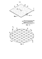
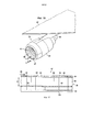
На фиг. 1 представлено изображение вида в перспективе композиционного слоистого материала, имеющего систему отверстий, сформированную в соответствии с описанным способом.In FIG. 1 is a perspective view of a composite laminate having a hole system formed in accordance with the described method.
На фиг. 1А представлено изображение области, обозначенной как «фиг. 1А» на фиг. 1.In FIG. 1A is an image of an area designated as “FIG. 1A "in FIG. one.
На фиг. 2 представлено изображение области, обозначенной как «фиг. 2» на фиг. 1.In FIG. 2 is an image of an area designated as “FIG. 2 ”in FIG. one.
На фиг. 3 представлено изображение вида в поперечном сечении по линии 3-3, показанной на фиг. 2.In FIG. 3 is a cross-sectional view taken along line 3-3 of FIG. 2.
На фиг. 3А представлено такое же изображение, как на фиг. 3, но демонстрирующее альтернативный вариант реализации композиционного слоистого материала, содержащего внедренный слой пористого материала.In FIG. 3A shows the same image as in FIG. 3, but showing an alternative embodiment of a composite laminate comprising an embedded layer of porous material.
На фиг. 4 представлено изображение вида сверху области, обозначенной как «фиг. 4» на фиг. 2.In FIG. 4 is a plan view of a region designated as “FIG. 4 ”in FIG. 2.
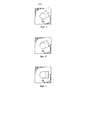
На фиг. 5 представлено изображение вида сверху, демонстрирующее отверстие шестиугольной формы.In FIG. 5 is a plan view showing a hexagonal hole.
На фиг. 6 представлено изображение вида сверху отверстия, имеющего восьмиугольную форму.In FIG. 6 is a plan view of a hole having an octagonal shape.
На фиг. 7 представлено изображение вида сверху отверстия, имеющего круглую форму.In FIG. 7 is a top view of a hole having a circular shape.
На фиг. 8 представлено изображение вида сверху, демонстрирующее слой с ориентацией волокон под углом 0°.In FIG. 8 is a plan view showing a layer with a fiber orientation at an angle of 0 °.
На фиг. 8А представлено изображение области, обозначенной как «фиг. 8А» на фиг. 8.In FIG. 8A is an image of an area designated as “FIG. 8A ”in FIG. 8.
На фиг. 9 представлено изображение вида сверху слоя с ориентацией волокон под углом 90°.In FIG. 9 is a top view of a layer with a fiber orientation of 90 °.
На фиг. 10 представлено изображение вида сверху слоя с ориентацией волокон под углом +45°.In FIG. 10 is a top view of a layer with fiber orientation at an angle of + 45 °.
На фиг. 11 представлено изображение вида сверху слоя с ориентацией волокон под углом -45°.In FIG. 11 is a top view of a layer with fiber orientation at an angle of -45 °.
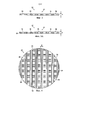
На фиг. 12 представлено изображение вида сверху нескольких выложенных поверх друг друга групп жгутов, расположенных с образованием требуемой системы отверстий в соответствии с описанным способом.In FIG. 12 is a top view of several bundle groups laid on top of each other arranged to form the desired hole system in accordance with the described method.
На фиг. 12А представлено изображение области, обозначенной как «фиг. 12А» на фиг. 12.In FIG. 12A is an image of a region designated as “FIG. 12A ”in FIG. 12.
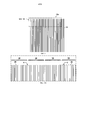
На фиг. 13 представлена обычная схема расположения слоев для изготовления композиционного слоистого материала, имеющего регулируемую систему отверстий.In FIG. 13 illustrates a conventional layering pattern for manufacturing a composite laminate having an adjustable hole system.
На фиг. 14 представлена комбинация блок-схемы и схематического изображения, демонстрирующая элементы автоматической системы для выкладки волокон, используемой для изготовления композиционных слоистых материалов, имеющих регулируемые системы отверстий.In FIG. 14 is a combination of a block diagram and a schematic diagram illustrating elements of an automatic fiber lining system used to make composite laminate materials having adjustable hole systems.
На фиг. 15 представлена блок-схема, демонстрирующая регулируемые по отдельности модули направления жгутов, образующие часть головки для выкладки ленты, показанной на фиг. 14.In FIG. 15 is a block diagram showing individually individually adjustable tow direction modules forming part of the head for laying out the tape shown in FIG. fourteen.
На фиг. 16 представлено изображение вида в перспективе части крыла, демонстрирующее двигатель с воздухозаборником, акустически обработанным с применением описанного композиционного слоистого материала.In FIG. 16 is a perspective view of a portion of a wing showing an engine with an air intake acoustically treated using the described composite laminate.
На фиг. 17 представлено изображение вида части акустической панели в поперечном сечении по линии 17-17, показанной на фиг. 16.In FIG. 17 is a cross-sectional view of a part of the acoustic panel taken along line 17-17 of FIG. 16.
На фиг. 18 представлена блок-схема способа изготовления композиционного слоистого материала, имеющего регулируемую систему отверстий.In FIG. 18 is a flowchart of a method for manufacturing a composite laminate having an adjustable hole system.
На фиг. 19 представлена блок-схема способа получения пакета слоев композиционного слоистого материала, имеющего регулируемую систему отверстий.In FIG. 19 is a flowchart of a method for producing a stack of layers of a composite laminate having an adjustable hole system.
На фиг. 20 представлена блок-схема производства воздушного судна и методика технического обслуживания.In FIG. 20 is a flowchart of aircraft manufacturing and a maintenance technique.
На фиг. 21 представлена блок-схема воздушного судна.In FIG. 21 is a block diagram of an aircraft.
ПОДРОБНОЕ ОПИСАНИЕDETAILED DESCRIPTION
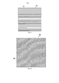
Ссылаясь на фиг. 1-3, композиционный слоистый материал 30 содержит множество перфораций или отверстий 34, которые расположены по схеме 32, здесь и далее иногда называемой системой 32 отверстий. В изображенном варианте реализации отверстия 34 проходят через всю толщину «D» слоистого материала 30, однако отверстия 34 могут быть сформированы так, что они лишь частично проходят через толщину «D». В изображенном варианте реализации система 32 отверстий представляет собой прямоугольную систему, в которой отверстия 34 расположены в определенной матрице, однако в других вариантах реализации система 32 отверстий может быть неупорядоченной, в зависимости от применения. Слоистый материал 30 содержит множество слоев 33 (фиг. 1А) армированной волокнами смолы, такой как, без ограничения, волокнистый эпоксиуглепластик или другая термореактивный, или армированный волокнами термопластичный материал.Referring to FIG. 1-3, the
В некоторых вариантах реализации, как показано на фиг. 3А, между слоями 33 может быть расположен один или более слоев 35 материала с получением слоистого материала 30 для конкретных применений. Внедренный слой 35 может быть тканым или нетканым материалом, или комбинацией тканых и нетканых материалов. Например, внедренный слой 35 может содержать пластиковую или проволочную сетку, предназначенную для улучшения акустических свойств слоистого материала 30.In some embodiments, as shown in FIG. 3A, between the
Ссылаясь на фиг. 1 и 4, каждый из слоев 33 может содержать смолу, армированную однонаправленными волокнами. Например, и без ограничения, смола, армированная однонаправленными волокнами, может содержать волокнистую ленту или жгуты 36 (разрезанную ленту), предварительно пропитанные термореактивной или термопластичной смолой. Жгуты 36 могут быть получены, например и без ограничения, посредством разрезания ленты препрега на полоски требуемой ширины «W». Как подробнее описано ниже, жгуты 36 отстоят друг от друга на некоторое расстояние и имеют такие ориентации волокон, которые приводят к получению отверстий 34, проходящих через слои 33.Referring to FIG. 1 and 4, each of the
В варианте реализации, изображенном на фиг. 1-4, отверстия 34 имеют по существу квадратную форму, однако возможны и другие формы отверстий. Например и без ограничения, слои 33 могут быть выложены друг на друга с образованием отверстий 34а, имеющих шестиугольную форму, показанную на фиг. 5, или восьмиугольную форму 34b, показанную на фиг. 6. В зависимости от количества слоев 33 могут быть получены отверстия 34 с, имеющие по существу круглую форму, как показано на фиг. 7. Помимо регулирования формы отверстий 34, с применением описанного способа может быть обеспечена также возможность регулирования величины или максимального размера в поперечном сечении «D».In the embodiment depicted in FIG. 1-4, the
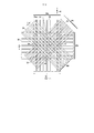
Слоистый материал 30 формируют выкладкой друг на друга множества слоев 33 (см. фиг. 1) однонаправленных волокон препрега, где указанные слои имеют разные ориентации волокон. Например, ссылаясь на фиг. 8, 9, 10 и 11, слоистый материал 30 может содержать слои 33а, 33b, 33с, 33d, соответственно, имеющие ориентации волокон под углом 0°, 90°, +45° и -45°, соответственно. В зависимости от применения возможны другие ориентации слоев, а также требуемые размер и форма отверстий 34. Ссылаясь на фиг. 8А, каждый из слоев 33 может быть сформирован посредством укладки по существу параллельных групп 38 жгутов 36 препрега, где жгуты 36 в каждой группе 38 отодвинуты друг от друга на требуемое расстояние с образованием зазоров «G» между жгутами 36. Размер, форма и положение отверстий 34 в системе 32 отверстий определяются ориентацией волокон в слоях 33, положением жгутов 36, шириной «W» жгутов 36 и размером зазоров «G».
Далее рассмотрены фиг. 12 и 12А, на которых изображены четыре перекрывающиеся группы 38а, 38b, 38 с, 38d, которые, соответственно, образуют часть слоев 33а, 33b, 33 с, 33d, изображенных на фиг. 8-11. Жгуты 36 в каждой группе 38 имеют требуемую ширину «W» и отстоят друг от друга на некоторое расстояние, образуя требуемый зазор «G». Зазоры «G» формируют посредством регулирования положений жгутов 36 относительно друг друга по мере укладки групп 38 при формировании слоев 33. Жгуты 36 в каждой группе 38 могут быть уложены в одну полосу 50 с применением, например, автоматического устройства для выкладки волокон, более подробно описанного ниже. Группы 48 и, следовательно, слои 33 содержат волокна, ориентированные относительно исходного направления, которое в иллюстрированном примере представляет собой направление X, под углом 0°.Next, FIGS. 12 and 12A, which depict four overlapping
На фиг. 13 представлена типичная схема расположения слоев композиционного слоистого материала 30 (фиг. 1), имеющего требуемую схему 32 отверстий. В указанном примере схема расположения слоев относится к слоистому материалу, содержащему 8 слоев 33, имеющих, соответственно, ориентации волокон под углом 0°, +45°, 90°, -45°, -45°, 90°, +45° и 0°. Группы 38а, 38b, 38c, 38d жгутов, изображенные на фиг. 12, соответственно, образуют части слоев 1-4, изображенных на схеме расположения слоев на фиг. 13. Зазоры «G» определены положением осевых линий 55 (фиг. 12) жгутов 36. Зазоры «G», ширина «W» жгутов 36 и ориентация слоев 33 определяют размер, положение и форму отверстий 34 в системе 32 отверстий.In FIG. 13 shows a typical layout of the layers of the composite laminate 30 (FIG. 1) having the desired
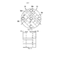
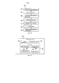
Каждый из слоев 33 слоистого материала 30 может быть выложен с помощью любого из нескольких известных устройство для автоматической выкладки волокон (AFP). Например, компоненты одного из известных устройство AFP показаны в общем виде на фиг. 14. Головка 58 для выкладки волокон может быть установлена на манипуляторе 77, управляемом контроллером 76, приводимым в действие одной или более цифровых программ 74 управления. Контроллер 76 может содержать компьютер общего назначения или программируемый логический контроллер (PLC). Контроллер 76 и манипулятор 77 приводят в действие головку 58 укладчика над подложкой 64 в требуемом направлении 66 для укладки множества групп 38 жгутов 36 с требуемой ориентацией волокон в соответствии со схемой расположения слоев, выбранной для данного применения.Each of the
Для простоты иллюстрации на фиг. 14 не показаны зазоры «G» между жгутами 36. Жгуты 36 могут поступать через коллиматор 70, который обеспечивает выравнивание и раздвигание жгутов 36. Выровненные жгуты 36 подают через подающие и направляющие ролики 72 и обрезают до требуемой длины группы с помощью одного или более ножей 60. Затем на подложку 64 наносят жгуты 36 и уплотняют валиком 68. В некоторых вариантах реализации для выкладки всех слоев 33 в слоистом материале 30 может быть использована одна головка 58 укладчика. Однако для укладки слоистого материала могут быть использованы несколько головок укладчика, в которые поступают жгуты разной ширины «W». Например, на фиг. 14 для ускорения процесса выкладки слоев контроллер 76, работающий синхронно с головкой 58 укладчика, приводит в действие вторую головку 81 укладчика, установленную на второй манипулятор 79.For simplicity, the illustration in FIG. 14, no “G” gaps are shown between the
Головки 58, 81 укладчика, изображенные на фиг. 14, могут осуществлять известное регулируемое размещение жгутов по типу, представленному на фиг. 15. Множество встроенных устройств 85 подачи жгутов обеспечивают доставку жгутов 36 от встроенного устройства подачи жгутов (не показано) к отдельным модулям 83 направления жгутов. Модули 83 направления жгутов выполнены с возможностью продольного движения 91 для регулирования зазора «G» между соседними жгутами 36 в каждой группе 38.The stacker heads 58, 81 shown in FIG. 14 may carry out known adjustable placement of harnesses of the type shown in FIG. 15. Many of the built-in
Как описано ранее, слоистый материал 30, имеющий регулируемую систему 32 отверстий, может быть использован во многих применениях акустической обработки. Например, ссылаясь на фиг. 16, двигатель 78 с высокой степенью двухконтурности установлен на крыло 82 воздушного судна с помощью кронштейна 80. Двигатель 20 содержит окружающую его гондолу 84 двигателя, имеющую воздухозаборник 86. Воздухозаборник 86 содержит акустически обработанную область 88 в форме акустической панели 87 для снижения шума, вызываемого вращающимися лопастями в двигателе 78.As described previously, the laminate 30 having an
Далее рассмотрена фиг. 17, которая представляет собой вид в поперечном сечении, иллюстрирующий дополнительные детали акустической панели 87. В общих чертах, панель 87 содержит ячеистую сотовую сердцевину 89, расположенную между внутренней и внешней листовой облицовкой 92, 102, соответственно. Внутренняя листовая облицовка 92 содержит множество перфораций, проходящих сквозь нее 44, которые обеспечивают возможность прохождения звуковых волн, включая шум, через внутреннюю листовую облицовку 92 в сердцевину 89. Описанный в настоящем документе композиционный слоистый материал 30, имеющий регулируемую систему отверстий, может быть использован в качестве внутренней листовой облицовки 92. Внутренняя листовая облицовка 92 прикреплена к поверхности ячеистой сердцевины 89 по линии 94 клеевого соединения. Точно также, внешняя листовая облицовка 102 прикреплена к внешней поверхности ячеистой сердцевины 89 по линии 100 клеевого соединения.Next, FIG. 17, which is a cross-sectional view illustrating additional details of the
В иллюстрированных вариантах реализации и внутренняя, и внешняя листовые облицовки 92, 102, соответственно, содержат слоистый композиционный материал, такой как CFRP (пластик, армированный углеродным волокном) или армированный волокном термопластичный материал, однако любая из указанных листовых облицовок может содержать другие материалы, такие как, без ограничения, керамический материал или металл, такой как алюминий. Ячеистая сердцевина 89 может содержать металл, такой как алюминий, полимер или другие материалы, и она состоит из множества отдельных многоугольных ячеек 96. В иллюстрированном примере ячейки 46 являются шестиугольными, однако возможны и другие геометрические формы ячеек. Ячеистая сердцевина 89 разделена на ячейки множеством отдельных перегородок 98, которые расположены в ячейках 96 на определенной глубине «D». Перегородки 98 способствуют погашению и ослаблению звуковых волн, поступающих в ячеистую сердцевину 89 через перфорации 90 во внутренней листовой облицовке 92.In the illustrated embodiments, both the inner and outer sheet claddings 92, 102, respectively, comprise a layered composite material such as CFRP (carbon fiber reinforced plastic) or fiber reinforced thermoplastic material, however, any of these sheet claddings may contain other materials such such as, without limitation, a ceramic material or metal such as aluminum.
На фиг. 18 в общих чертах представлены общие этапы осуществления способа получения композиционного слоистого материала, имеющего требуемую систему 32 отверстий 34. На этапе 104 формируют многослойный пакет 30, используя жгуты 36 препрега с зазорами «G» между ними. На этапе 106 варьируют ориентацию волокон в слоях 33 для формирования системы 32 отверстий 34 в слоистом материале 30.In FIG. 18 generally outlines the general steps for implementing a method for producing a composite laminate having the desired system of 32
На фиг. 19 в общих чертах представлены общие этапы осуществления способа получения пакета слоев композиционного слоистого материала, имеющего систему 32 отверстий 34. На этапе 108 формируют пакет слоев посредством выкладки множества слоев 33 однонаправленных волокон препрега. Выкладка слоев 33 может быть осуществлена посредством укладки полос 50 жгутов 36 волокон препрега. На этапе 110 жгуты 36 в каждой из полос 50 отодвигают друг от друга с получением зазоров «G» между жгутами 36 при укладке полос 50. На этапе 112 регулируют положение жгутов 36 при укладке полос 50. Точно так же, на этапе 114 регулируют зазоры «G» между жгутами 36 при укладке полос 50. На этапе 116 варьируют ориентацию волокон в слоях 33 для формирования системы 32 отверстий 34 в пакете слоев. Готовый слоистый материал может быть отвержден с применением безавтоклавного процесса, в котором используют вакуумное давление для облегчения регулирования потока смолы и предотвращения затекания смолы в отверстия 34 при отверждении. В альтернативном варианте отверждение слоистого материала 30 может быть осуществлено в автоклаве, при условии, что используемая смола имеет более высокую вязкость, которая обеспечивает такие характеристики течения смолы, которые препятствуют затеканию смолы в отверстия 34 в процессе отверждения.In FIG. 19 outlines the general steps of implementing a method for producing a stack of layers of a composite laminate having a system of 32
Варианты реализации настоящего изобретения могут находить применение в различных потенциальных областях, в частности, в транспортной промышленности, включая, например, аэрокосмическую промышленность, судостроение, автомобилестроение, а также в других областях, в которых могут быть использованы композиционные слоистые материалы, имеющие регулируемую систему отверстий. Так, ссылаясь на фиг. 20 и 21, варианты реализации настоящего описания могут быть использованы в контексте производства воздушных суден и способа 118 технического обслуживания, как показано на фиг. 20, а также в воздушном судне 120, как показано на фиг. 21. Применения описанных вариантов реализации в воздушных суднах могут включать, например, без ограничения, акустические панели для ослабления звука или для изменения воздушного потока над крылом. На стадии предварительного производства иллюстративный способ 118 может включать разработку и проектирование 122 воздушного судна 120, а также закупку 124 материалов. Во время производства осуществляют изготовление 126 компонентов и сборку узлов, а также интеграцию 128 систем воздушного судна 120. Описанные варианты реализации могут быть использованы на стадии изготовления и сборки деталей узлов, имеющих регулируемые системы отверстий. Затем воздушное судно 120 может проходить сертификацию и доставку 130 для ввода в эксплуатацию 132. В течение срока эксплуатации заказчиком воздушное судно 120 подлежит регулярному техническому обеспечению и обслуживанию 134, которое также может включать модификацию, перенастройку, модернизацию и т.д. Во время технического обеспечения и обслуживания 134 на воздушное судно 122 могут быть установлены запасные детали или узлы, которые могут содержать системы отверстий, сформированные по описанному способу.Embodiments of the present invention may find application in various potential areas, in particular in the transportation industry, including, for example, the aerospace industry, shipbuilding, automotive, as well as in other areas in which composite layered materials having an adjustable hole system can be used. So, referring to FIG. 20 and 21, embodiments of the present disclosure may be used in the context of aircraft manufacturing and
Каждый из процессов в соответствии со способом 118 может быть осуществлен или выполнен компанией, занимающейся системной интеграцией, третьей стороной и/или авиакомпанией (например, заказчиком). В контексте настоящего описания компания, занимающаяся системной интеграцией, может включать, без ограничения, любое количество производителей воздушных суден и субподрядчиков главных систем; третья сторона может включать, без ограничения, любое количество посредников, субподрядчиков и поставщиков; и авиакомпания может быть авиационной компанией, лизинговой компанией, военной организацией, обслуживающей организацией и т.д.Each of the processes in accordance with
Как показано на фиг. 21, воздушное судно 120, изготовленное по иллюстративному способу 118, может содержать корпус 136 с множеством систем 128 и внутреннюю часть 140. Примеры систем 138 высокого уровня включают одну или более из винтомоторных систем 142, электрических систем 144, гидравлических систем 146 и систем 148 искусственного климата. Может быть включено любое количество других систем. Описанный способ может быть использован для изготовления деталей и узлов, формирующих часть корпуса 136 и/или винтомоторной системы 142. Например, описанный способ может быть использован для получения акустических панелей, имеющих регулируемые системы отверстий, которые обеспечивают снижение шума, создаваемого двигателями, составляющими часть винтомоторной системы 142. Точно так же, описанный способ может быть использовано для получения панелей или обшивки, имеющей регулируемую систему отверстий, которая составляет часть корпуса 136 или которую используют во внутренней части 140 для снижения шума. Несмотря на представленный пример применения в аэрокосмической области, принципы настоящего описания могут быть применены к другим отраслям промышленности, таким как судостроение и автомобилестроение.As shown in FIG. 21, an
Системы и способы, осуществленные в настоящем документе, могут быть использованы на любом одном или более этапах способа 118 производства и обслуживания. Например, детали или узлы, соответствующие процессу 126 производства, могут быть изготовлены или произведены по такому же способу, как детали или компоненты, изготовленные при эксплуатации воздушного судна 120. Кроме того, один или более вариантов реализации устройства, вариантов реализации способа или их комбинации могут быть использованы на стадиях 126 и 128 производства, например, для значительного ускорения сборки или снижения стоимости воздушного судна 120. Точно так же, один или более вариантов реализации устройства, вариантов реализации способа или их комбинации могут быть использованы при эксплуатации воздушного судна 120, например и без ограничения, для технического обеспечения и обслуживания 134.The systems and methods implemented herein can be used in any one or more steps of the manufacturing and
В контексте настоящего документа выражение «по меньшей мере один из», используемое с перечнем элементов, означает, что могут быть использованы различные комбинации одного или более перечисленных элементов и что может быть необходим лишь один элемент из перечня. Например, «по меньшей мере один из элемента А, элемента В и элемента С» может включать, без ограничения, элемент А, элемент А и элемент В, или элемент В. Представленный пример также может включать элемент А, элемент В и элемент С или элемент В и элемент С.Элемент может представлять собой конкретный объект, предмет или категорию. Другими словами, «по меньшей мере один» означает, что может быть использована любая комбинация элементов и любое количество элементов перечня, но не все элементы перечня являются необходимыми.In the context of this document, the expression “at least one of” used with a list of elements means that various combinations of one or more of the listed elements may be used and that only one element from the list may be needed. For example, “at least one of element A, element B and element C” may include, without limitation, element A, element A and element B, or element B. The presented example may also include element A, element B and element C or Element B and Element C. An element can be a specific object, item, or category. In other words, “at least one” means that any combination of items and any number of items in the list can be used, but not all items in the list are necessary.
Таким образом, подводя итог, в соответствии с первым аспектом настоящего изобретения предложен:Thus, summing up, in accordance with the first aspect of the present invention proposed:
А1. Способ получения композиционного слоистого материала, имеющего систему отверстий, включающий:A1. A method of obtaining a composite layered material having a system of holes, including:
формирование пакета слоев посредством выкладки друг на друга множества слоев армированной волокнами смолы, где каждый из слоев имеет определенную ориентацию волокон и содержит множество жгутов из армированной волокнами смолы с зазорами между ними;forming a stack of layers by laying on each other a plurality of layers of fiber reinforced resin, where each of the layers has a specific orientation of the fibers and contains many strands of fiber reinforced resin with gaps between them;
иand
варьирование ориентации волокон в слоях пакета слоев с получением системы отверстий в композиционном слоистом материале.varying the orientation of the fibers in the layers of the package of layers with obtaining a system of holes in the composite laminate.
А2. Предложен также способ в соответствии с абзацем А1, дополнительно включающий:A2. Also proposed is a method in accordance with paragraph A1, further comprising:
регулирование зазоров между жгутами в каждом из слоев.regulation of the gaps between the bundles in each of the layers.
A3. Предложен также способ в соответствии с абзацем А1, отличающийся тем, что выкладка друг на друга множества слоев включает применение жгутов, имеющих по меньшей мере две разные ширины, соответственно, в по меньшей мере двух из слоев.A3. Also proposed is a method in accordance with paragraph A1, characterized in that laying on each other a plurality of layers includes the use of bundles having at least two different widths, respectively, in at least two of the layers.
А4. Предложен также способ в соответствии с абзацем А1, отличающийся тем, что выкладку множества слоев осуществляют автоматически с помощью устройства для выкладки волокон с цифровым управлением.A4. A method is also proposed in accordance with paragraph A1, characterized in that the laying out of the plurality of layers is carried out automatically using a digitally controlled fiber laying device.
А5. Предложен также способ в соответствии с абзацем А1, дополнительно включающий:A5. Also proposed is a method in accordance with paragraph A1, further comprising:
включение по меньшей мере одного тканого или нетканого материала в указанное множество слоев.the inclusion of at least one woven or non-woven material in the specified many layers.
А6. Предложен также способ в соответствии с абзацем А1, дополнительно включающий:A6. Also proposed is a method in accordance with paragraph A1, further comprising:
выбор системы отверстий; иchoice of hole system; and
программирование автоматического устройства для выкладки волокон для автоматической выкладки друг на друга слоев с применением раздвинутых жгутов, а также для изменения ориентации волокон в слоях для формирования выбранной системы отверстий.programming an automatic device for laying out fibers to automatically lay out layers on top of each other using extended bundles, as well as to change the orientation of the fibers in the layers to form the selected hole system.
А7. Предложен также способ в соответствии с абзацем А6, дополнительно включающий:A7. Also proposed is a method in accordance with paragraph A6, further comprising:
выбор размера и формы отверстий; иselection of size and shape of holes; and
программирование автоматического устройства для выкладки волокон для автоматической выкладки друг на друга слоев и варьирования ориентации волокон в слоях для формирования отверстий, имеющих выбранные размер и форму.programming an automatic device for laying out fibers for automatically laying out layers on each other and varying the orientation of the fibers in the layers to form holes with selected size and shape.
А8. Предложен также способ в соответствии с абзацем А1, дополнительно включающий:A8. Also proposed is a method in accordance with paragraph A1, further comprising:
отверждение пакета слоев; иcuring the package of layers; and
выбор смолы, обладающей контролируемыми характеристиками течения, которые по существу препятствуют затеканию смолы в отверстия в процессе отверждения.selecting a resin having controlled flow characteristics that substantially prevent the resin from flowing into the holes during the curing process.
А9. Предложен также способ в соответствии с абзацем А8, отличающийся тем, что отверждение пакета слоев осуществляют с применением безавтоклавного и автоклавного процесса отверждения.A9. A method is also proposed in accordance with paragraph A8, characterized in that the curing of the package of layers is carried out using an autoclave-free and autoclave curing process.
В соответствии с дополнительным аспектом настоящего изобретения предложен:In accordance with a further aspect of the present invention, there is provided:
81. Способ получения пакета слоев композиционного слоистого материала, имеющего систему отверстий, включающий:81. A method of obtaining a package of layers of a composite laminate having a system of holes, including:
формирование пакета слоев посредством выкладки друг на друга множества слоев препрега с однонаправленными волокнами, каждый из которых выкладывают посредством укладки полос волокнистых жгутов препрега;the formation of a package of layers by laying on top of each other many layers of the prepreg with unidirectional fibers, each of which is laid out by laying strips of fiber bundles of the prepreg;
отодвигание жгутов в каждой полосе друг от друга с получением зазоров между жгутами при укладке полос;pushing the harnesses in each strip from each other to obtain gaps between the harnesses when laying strips;
регулирование положений жгутов при укладке полос;regulation of the positions of the harnesses when laying strips;
регулирование зазоров между жгутами при укладке полос; иregulation of gaps between plaits when laying strips; and
изменение ориентации волокон в слоях с получением системы отверстий в пакете слоев.changing the orientation of the fibers in the layers to obtain a system of holes in the package of layers.
82. Предложен также способ в соответствии с абзацем В1, отличающийся тем, что каждый из слоев выкладывают с помощью устройства для выкладки волокон с цифровым управлением.82. A method is also proposed in accordance with paragraph B1, characterized in that each of the layers is laid out using a digitally controlled fiber laying device.
83. Предложен также способ в соответствии с абзацем В1, отличающийся тем, что раздвигание жгутов включает изменение зазоров между жгутами.83. A method is also proposed in accordance with paragraph B1, characterized in that the extension of the bundles involves changing the gaps between the bundles.
84. Предложен также способ в соответствии с абзацем В1, дополнительно включающий варьирование ширины жгутов.84. A method is also proposed in accordance with paragraph B1, further comprising varying the width of the bundles.
85. Предложен также способ в соответствии с абзацем В1, дополнительно включающий:85. A method is also proposed in accordance with paragraph B1, further comprising:
включение по меньшей мере одного тканого или нетканого материала между слоями пакета слоев.the inclusion of at least one woven or non-woven material between the layers of the package layers.
86. Предложен также способ в соответствии с абзацем В1, дополнительно включающий:86. A method is also proposed in accordance with paragraph B1, further comprising:
выбор положения отверстий, размера отверстий и формы отверстий; иselection of hole position, hole size and hole shape; and
программирование автоматического устройства для выкладки волокон для автоматической выкладки друг на друга слоев и варьирования ориентации волокон в слоях для формирования системы отверстий.programming an automatic device for laying fibers to automatically lay layers on each other and varying the orientation of the fibers in the layers to form a system of holes.
B7. Предложен также способ в соответствии с абзацем В1, дополнительно включающий:B7. Also proposed is a method in accordance with paragraph B1, further comprising:
отверждение пакета слоев; иcuring the package of layers; and
выбор смолы, обладающей контролируемыми характеристиками течения, которые по существу препятствуют затеканию смолы в отверстия в процессе отверждения.selecting a resin having controlled flow characteristics that substantially prevent the resin from flowing into the holes during the curing process.
С1. Композиционный слоистый материал, имеющий систему отверстий, содержащий:C1. A composite laminate having an aperture system comprising:
множество отстоящих друг от друга волокнистых жгутов, имеющих переменную ориентацию волокон, расположенных для получения системы отверстий в слоистом материале; иa plurality of spaced fiber bundles having a variable orientation of fibers arranged to produce a system of holes in the laminate; and
смолистую матрицу, в которую заделаны волокнистые жгуты.resinous matrix into which the fiber bundles are embedded.
С2. Предложен также композиционный слоистый материал в соответствии с абзацем С1, отличающийся тем, что волокнистые жгуты расположены во множестве слоев с различной ориентацией волокон.C2. A composite layered material is also proposed in accordance with paragraph C1, characterized in that the fiber bundles are arranged in a plurality of layers with different fiber orientations.
С3. Предложен также композиционный слоистый материал в соответствии с абзацем С1, отличающийся тем, что волокнистые жгуты имеют разную ширину.C3. A composite layered material is also proposed in accordance with paragraph C1, characterized in that the fiber bundles have different widths.
С4. Предложен также композиционный слоистый материал в соответствии с абзацем С1, отличающийся тем, что каждое отверстие имеет многоугольную форму.C4. A composite layered material is also proposed in accordance with paragraph C1, wherein each hole has a polygonal shape.
С5. Предложен также композиционный слоистый материал в соответствии с абзацем С1, отличающийся тем, что смолистая матрица представляет собой термически отверждаемый термореактивный материал, обладающий характеристиками течения, которые препятствуют затеканию термореактивного материала в отверстия при термическом отверждении.C5. A composite layered material is also proposed in accordance with paragraph C1, characterized in that the resinous matrix is a thermally curable thermosetting material having flow characteristics that prevent the thermosetting material from flowing into holes during thermal curing.
D1. Пакет слоев композиционного слоистого материала, имеющий систему отверстий, содержащий:D1. A package of layers of composite laminate having a system of holes containing:
множество слоев армированной волокнами смолы, где каждый из слоев имеет волокна, ориентированные в одном направлении, и содержит множество жгутов препрега с зазорами между ними; иa plurality of layers of fiber-reinforced resin, where each of the layers has fibers oriented in one direction, and contains a plurality of prepreg tows with gaps between them; and
слои расположены так, чтобы зазоры между жгутами препрега образовывали систему отверстий в пакете слоев.the layers are arranged so that the gaps between the prepreg strands form a system of holes in the layer stack.
D2. Предложен также пакет слоев композиционного слоистого материала в соответствии с абзацем D1, отличающийся тем, что смола является термически отверждаемой и имеет при отверждении такие характеристики течения, которые препятствуют затеканию смолы в отверстия.D2. Also proposed is a package of layers of composite laminate in accordance with paragraph D1, characterized in that the resin is thermally curable and has during curing such flow characteristics that prevent the resin from flowing into the holes.
D3. Предложен также композиционный слоистый материал в соответствии с абзацем D1, отличающийся тем, что зазоры между жгутами препрега варьируются.D3. A composite layered material is also proposed in accordance with paragraph D1, characterized in that the gaps between the prepreg strands vary.
D4. Предложен также композиционный слоистый материал в соответствии с абзацем D1, отличающийся тем, что каждый жгут имеет ширину, и ширина жгутов варьируется от слоя к слою.D4. A composite layered material is also proposed in accordance with paragraph D1, characterized in that each bundle has a width, and the width of the bundles varies from layer to layer.
Описание различных иллюстративных вариантов реализации представлено для демонстрации и описания, и оно не предназначено быть исчерпывающим или ограниченным до вариантов реализации в описанной форме. Специалистам в данной области техники станут понятны многочисленные модификации и вариации. Кроме того, одни иллюстративные варианты реализации могут обеспечивать другие преимущества по сравнению с другими иллюстративными вариантами реализации. Выбранный вариант или варианты реализации выбраны и описаны для наилучшего пояснения принципов вариантов реализации, практического применения и обеспечения возможности понимания специалистами в данной области техники настоящего описания для различных вариантов реализации с различными модификациями, подходящими для конкретного предполагаемого применения.The description of various illustrative embodiments is presented for demonstration and description, and it is not intended to be exhaustive or limited to the embodiments in the described form. Numerous modifications and variations will become apparent to those skilled in the art. In addition, some illustrative embodiments may provide other advantages compared to other illustrative embodiments. The selected option or options for implementation are selected and described to best explain the principles of the options for implementation, practical application and to ensure that experts in the art can understand the present description for various embodiments with various modifications suitable for the particular intended application.
Claims (22)
Applications Claiming Priority (3)
| Application Number | Priority Date | Filing Date | Title |
|---|---|---|---|
| US13/953,392 | 2013-07-29 | ||
| US13/953,392 US20150030803A1 (en) | 2013-07-29 | 2013-07-29 | Composite Laminates Having Hole Patterns Produced by Controlled Fiber Placement |
| PCT/US2014/042522 WO2015017033A1 (en) | 2013-07-29 | 2014-06-16 | Composite laminates having hole patterns produced by controlled fiber placement |
Related Child Applications (1)
| Application Number | Title | Priority Date | Filing Date |
|---|---|---|---|
| RU2018118625A Division RU2765421C2 (en) | 2013-07-29 | 2014-06-16 | Composite layered materials containing system of holes obtained by adjustable fiber layout |
Publications (2)
| Publication Number | Publication Date |
|---|---|
| RU2015149039A RU2015149039A (en) | 2017-09-01 |
| RU2656657C2 true RU2656657C2 (en) | 2018-06-06 |
Family
ID=51179162
Family Applications (2)
| Application Number | Title | Priority Date | Filing Date |
|---|---|---|---|
| RU2018118625A RU2765421C2 (en) | 2013-07-29 | 2014-06-16 | Composite layered materials containing system of holes obtained by adjustable fiber layout |
| RU2015149039A RU2656657C2 (en) | 2013-07-29 | 2014-06-16 | Composite layer materials containing the pattern of holes produced by controlled fiber placement |
Family Applications Before (1)
| Application Number | Title | Priority Date | Filing Date |
|---|---|---|---|
| RU2018118625A RU2765421C2 (en) | 2013-07-29 | 2014-06-16 | Composite layered materials containing system of holes obtained by adjustable fiber layout |
Country Status (8)
| Country | Link |
|---|---|
| US (1) | US20150030803A1 (en) |
| EP (1) | EP3027405B1 (en) |
| JP (2) | JP6495275B2 (en) |
| CN (1) | CN105431286A (en) |
| BR (1) | BR112015032418A8 (en) |
| CA (2) | CA2916411C (en) |
| RU (2) | RU2765421C2 (en) |
| WO (1) | WO2015017033A1 (en) |
Families Citing this family (20)
| Publication number | Priority date | Publication date | Assignee | Title |
|---|---|---|---|---|
| US11728768B2 (en) | 2006-12-06 | 2023-08-15 | Solaredge Technologies Ltd. | Pairing of components in a direct current distributed power generation system |
| US9643392B2 (en) | 2013-07-29 | 2017-05-09 | The Boeing Company | Septumization of honeycomb sandwiches |
| US9693166B2 (en) | 2014-06-24 | 2017-06-27 | The Boeing Company | Automated production of acoustic structures |
| EP3299153A4 (en) * | 2015-05-21 | 2019-02-20 | Mitsubishi Electric Corporation | Honeycomb core, honeycomb sandwiching structure, and method for producing honeycomb core |
| CN106796617B (en) * | 2015-08-11 | 2018-09-25 | 沙特基础工业全球技术公司 | More plate layer laminar composites with low aerial weight |
| US10399276B2 (en) | 2015-08-12 | 2019-09-03 | General Electric Company | System and method for controlling at least one variable during layup of a composite part using automated fiber placement |
| US10369756B2 (en) * | 2015-08-25 | 2019-08-06 | The Boeing Company | Method of manufacturing a composite article |
| CN110461918B (en) * | 2017-03-31 | 2022-06-28 | 三菱化学株式会社 | Prepreg and method for producing same, cell layer with skin material, fiber-reinforced composite material molded article, and method for producing same |
| EP3638832A4 (en) * | 2017-06-13 | 2020-10-28 | Honeywell International Inc. | Breathable light weight unidirectional laminates |
| BR112020011357B1 (en) * | 2017-12-06 | 2023-12-19 | Safran Aircraft Engines | METHOD FOR IN SITU DEPOSITION OF A COATING BY ADDITIVE MANUFACTURING, SYSTEM FOR DEPOSITION OF FILAMENTARY MATERIAL, AND COATING OF TURBOM MACHINE WALLS SUSCEPTIBLE TO ABRASION |
| FR3074444A1 (en) * | 2017-12-06 | 2019-06-07 | Safran Aircraft Engines | METHOD FOR MANUFACTURING AN ORDINARY ORDER OF ACOUSTIC CHANNELS IN ABRADABLE MATERIAL |
| CN111655452B (en) * | 2017-12-06 | 2023-01-17 | 赛峰航空器发动机 | Method for making an ordered network of acoustic channels from a wear-resistant material |
| US11534992B2 (en) | 2019-03-04 | 2022-12-27 | The Boeing Company | Tooling assembly and associated system and method for manufacturing a porous composite structure |
| US11413833B2 (en) | 2019-03-04 | 2022-08-16 | The Boeing Company | Tooling assembly and associated system and method for manufacturing a porous composite structure |
| JP7249404B2 (en) * | 2019-03-29 | 2023-03-30 | 川崎重工業株式会社 | Composite material panel structure and manufacturing method thereof |
| KR102311748B1 (en) * | 2019-08-05 | 2021-10-13 | 한국과학기술연구원 | Sound absorption device and Method of manufacturing the same |
| CN111016301B (en) * | 2020-01-10 | 2023-11-17 | 杭州友凯船艇有限公司 | Reinforcing and preparing scheme for periphery of fiber composite material connecting hole |
| CN113002008B (en) * | 2021-04-30 | 2022-02-22 | 浙江大学 | Composite material grid structure without carbon fiber accumulation at grid intersection and manufacturing method |
| WO2023286174A1 (en) * | 2021-07-13 | 2023-01-19 | ギガフォトン株式会社 | Composite component, laser processing method, and method for producing composite component |
| US20230040244A1 (en) * | 2021-08-06 | 2023-02-09 | Raytheon Technologies Corporation | Composite fan blade airfoil, methods of manufacture thereof and articles comprising the same |
Citations (4)
| Publication number | Priority date | Publication date | Assignee | Title |
|---|---|---|---|---|
| US20070175571A1 (en) * | 2006-02-02 | 2007-08-02 | Rubin Alexander M | Novel fabrication process for thermoplastic composite parts |
| US20100065367A1 (en) * | 2008-09-17 | 2010-03-18 | General Electric Company | Method of Manufacture of Composite Laminates, an Assembly Therefor, and Related Articles |
| RU2385231C1 (en) * | 2008-07-21 | 2010-03-27 | Федеральное государственное унитарное предприятие "Обнинское научно-производственное предприятие "Технология" | Method to produce laminar products from polymer composite material |
| US20100247838A1 (en) * | 2009-03-24 | 2010-09-30 | The Boeing Company | Method of making bead-stiffened composite parts and parts made thereby |
Family Cites Families (12)
| Publication number | Priority date | Publication date | Assignee | Title |
|---|---|---|---|---|
| US3765980A (en) * | 1971-09-24 | 1973-10-16 | Combination Eng Inc | Method for forming pipe with integral hole or nozzle pattern |
| US4600619A (en) * | 1984-12-31 | 1986-07-15 | The Boeing Company | Continuously wound filament structure for use in noise attenuation element |
| JPH07173824A (en) * | 1993-11-04 | 1995-07-11 | Mitsui Toatsu Chem Inc | Ground reinforcer |
| JP2001521839A (en) * | 1997-11-05 | 2001-11-13 | シコルスキー エアクラフト コーポレイション | Supply control system for fiber placement device |
| GB2401346B (en) * | 2003-05-07 | 2005-04-13 | Oxford Magnet Tech | A structural composite material for acoustic damping |
| EP2021237A1 (en) * | 2006-05-30 | 2009-02-11 | Airbus Deutschland GmbH | Sandwich element for sound-absorbing inner cladding of transport means, especially for sound-absorbing inner cladding of aircraft fuselage cells |
| JP4990181B2 (en) * | 2007-07-06 | 2012-08-01 | 三菱電機株式会社 | Advanced grid structure |
| US9278484B2 (en) * | 2008-04-17 | 2016-03-08 | The Boeing Company | Method and apparatus for producing contoured composite structures and structures produced thereby |
| US9090028B2 (en) * | 2008-04-17 | 2015-07-28 | The Boeing Company | Method for producing contoured composite structures and structures produced thereby |
| FR2953058B1 (en) * | 2009-11-23 | 2017-11-03 | Aircelle Sa | ACOUSTIC SKIN FOR AN ACOUSTIC PANEL OF AN AIRCRAFT NACELLE |
| JP5836885B2 (en) * | 2011-08-05 | 2015-12-24 | 三菱電機株式会社 | Advanced grid structure manufacturing method, advanced grid structure, and space telescope using the advanced grid structure |
| US20140081444A1 (en) * | 2012-09-18 | 2014-03-20 | Todd W. Rudberg | Sequencer system for an automatic tape laying and projection system |
-
2013
- 2013-07-29 US US13/953,392 patent/US20150030803A1/en not_active Abandoned
-
2014
- 2014-06-16 CA CA2916411A patent/CA2916411C/en active Active
- 2014-06-16 BR BR112015032418A patent/BR112015032418A8/en not_active Application Discontinuation
- 2014-06-16 WO PCT/US2014/042522 patent/WO2015017033A1/en active Application Filing
- 2014-06-16 RU RU2018118625A patent/RU2765421C2/en active
- 2014-06-16 CN CN201480042807.XA patent/CN105431286A/en active Pending
- 2014-06-16 EP EP14739304.5A patent/EP3027405B1/en active Active
- 2014-06-16 RU RU2015149039A patent/RU2656657C2/en active
- 2014-06-16 JP JP2016531613A patent/JP6495275B2/en active Active
- 2014-06-16 CA CA3112536A patent/CA3112536C/en active Active
-
2018
- 2018-12-06 JP JP2018228829A patent/JP2019073021A/en active Pending
Patent Citations (4)
| Publication number | Priority date | Publication date | Assignee | Title |
|---|---|---|---|---|
| US20070175571A1 (en) * | 2006-02-02 | 2007-08-02 | Rubin Alexander M | Novel fabrication process for thermoplastic composite parts |
| RU2385231C1 (en) * | 2008-07-21 | 2010-03-27 | Федеральное государственное унитарное предприятие "Обнинское научно-производственное предприятие "Технология" | Method to produce laminar products from polymer composite material |
| US20100065367A1 (en) * | 2008-09-17 | 2010-03-18 | General Electric Company | Method of Manufacture of Composite Laminates, an Assembly Therefor, and Related Articles |
| US20100247838A1 (en) * | 2009-03-24 | 2010-09-30 | The Boeing Company | Method of making bead-stiffened composite parts and parts made thereby |
Also Published As
| Publication number | Publication date |
|---|---|
| US20150030803A1 (en) | 2015-01-29 |
| RU2765421C2 (en) | 2022-01-31 |
| CA3112536C (en) | 2023-07-11 |
| JP2016525471A (en) | 2016-08-25 |
| CN105431286A (en) | 2016-03-23 |
| EP3027405A1 (en) | 2016-06-08 |
| CA3112536A1 (en) | 2015-02-05 |
| WO2015017033A1 (en) | 2015-02-05 |
| RU2018118625A3 (en) | 2021-08-16 |
| RU2018118625A (en) | 2018-11-05 |
| RU2015149039A (en) | 2017-09-01 |
| CA2916411C (en) | 2021-02-16 |
| BR112015032418A8 (en) | 2020-01-14 |
| BR112015032418A2 (en) | 2017-07-25 |
| CA2916411A1 (en) | 2015-02-05 |
| JP2019073021A (en) | 2019-05-16 |
| EP3027405B1 (en) | 2024-03-06 |
| JP6495275B2 (en) | 2019-04-03 |
Similar Documents
| Publication | Publication Date | Title |
|---|---|---|
| RU2656657C2 (en) | Composite layer materials containing the pattern of holes produced by controlled fiber placement | |
| JP6906017B2 (en) | Formation of septum for cellular core | |
| CN104417761B (en) | System and method for forming perforation in cylinder section | |
| CN105523175B (en) | Perforated surface for suction lamination flow control | |
| EP2386483A2 (en) | Curved composite frames and method of making the same | |
| US20070187024A1 (en) | Composite material placement method and system | |
| JP7017318B2 (en) | Acoustic panel material | |
| US9302869B2 (en) | System and method of manufacturing composite core | |
| WO2011107733A2 (en) | Seamless acoustic liner | |
| JP2012527375A (en) | Method of forming structure with lightning protection | |
| EP2772344A1 (en) | System and method of manufacturing composite core | |
| US10562202B2 (en) | System and method of post-cure processing of composite core | |
| EP3839939B1 (en) | Structural single degree of freedom face sheet acoustic liner | |
| GB2486120A (en) | Manufacturing composite acoustic panels | |
| CN108237703B (en) | Method for obtaining a porous acoustic absorption layer and porous acoustic absorption layer obtained thereby | |
| US20150360440A1 (en) | Pre-Filled Radius Layups | |
| CN111645337B (en) | Tool assembly for fabricating porous composite structures and related systems and methods | |
| EP2960043A1 (en) | System and method of manufaturing composite core | |
| US9757906B2 (en) | Methods of making composite charges | |
| JP6947844B2 (en) | Method of manufacturing two or more fiber composite parts at the same time |