RU2654046C2 - Distributed arc fault protection between outlet and circuit breaker - Google Patents
Distributed arc fault protection between outlet and circuit breaker Download PDFInfo
- Publication number
- RU2654046C2 RU2654046C2 RU2016105243A RU2016105243A RU2654046C2 RU 2654046 C2 RU2654046 C2 RU 2654046C2 RU 2016105243 A RU2016105243 A RU 2016105243A RU 2016105243 A RU2016105243 A RU 2016105243A RU 2654046 C2 RU2654046 C2 RU 2654046C2
- Authority
- RU
- Russia
- Prior art keywords
- branch
- voltage
- current
- controller
- measuring
- Prior art date
Links
Images


Classifications
-
- H—ELECTRICITY
- H02—GENERATION; CONVERSION OR DISTRIBUTION OF ELECTRIC POWER
- H02H—EMERGENCY PROTECTIVE CIRCUIT ARRANGEMENTS
- H02H3/00—Emergency protective circuit arrangements for automatic disconnection directly responsive to an undesired change from normal electric working condition with or without subsequent reconnection ; integrated protection
- H02H3/26—Emergency protective circuit arrangements for automatic disconnection directly responsive to an undesired change from normal electric working condition with or without subsequent reconnection ; integrated protection responsive to difference between voltages or between currents; responsive to phase angle between voltages or between currents
- H02H3/28—Emergency protective circuit arrangements for automatic disconnection directly responsive to an undesired change from normal electric working condition with or without subsequent reconnection ; integrated protection responsive to difference between voltages or between currents; responsive to phase angle between voltages or between currents involving comparison of the voltage or current values at two spaced portions of a single system, e.g. at opposite ends of one line, at input and output of apparatus
-
- H—ELECTRICITY
- H01—ELECTRIC ELEMENTS
- H01H—ELECTRIC SWITCHES; RELAYS; SELECTORS; EMERGENCY PROTECTIVE DEVICES
- H01H9/00—Details of switching devices, not covered by groups H01H1/00 - H01H7/00
- H01H9/54—Circuit arrangements not adapted to a particular application of the switching device and for which no provision exists elsewhere
-
- H—ELECTRICITY
- H02—GENERATION; CONVERSION OR DISTRIBUTION OF ELECTRIC POWER
- H02H—EMERGENCY PROTECTIVE CIRCUIT ARRANGEMENTS
- H02H1/00—Details of emergency protective circuit arrangements
- H02H1/0007—Details of emergency protective circuit arrangements concerning the detecting means
- H02H1/0015—Using arc detectors
-
- H—ELECTRICITY
- H02—GENERATION; CONVERSION OR DISTRIBUTION OF ELECTRIC POWER
- H02H—EMERGENCY PROTECTIVE CIRCUIT ARRANGEMENTS
- H02H3/00—Emergency protective circuit arrangements for automatic disconnection directly responsive to an undesired change from normal electric working condition with or without subsequent reconnection ; integrated protection
- H02H3/26—Emergency protective circuit arrangements for automatic disconnection directly responsive to an undesired change from normal electric working condition with or without subsequent reconnection ; integrated protection responsive to difference between voltages or between currents; responsive to phase angle between voltages or between currents
-
- H—ELECTRICITY
- H02—GENERATION; CONVERSION OR DISTRIBUTION OF ELECTRIC POWER
- H02H—EMERGENCY PROTECTIVE CIRCUIT ARRANGEMENTS
- H02H7/00—Emergency protective circuit arrangements specially adapted for specific types of electric machines or apparatus or for sectionalised protection of cable or line systems, and effecting automatic switching in the event of an undesired change from normal working conditions
- H02H7/26—Sectionalised protection of cable or line systems, e.g. for disconnecting a section on which a short-circuit, earth fault, or arc discharge has occured
- H02H7/261—Sectionalised protection of cable or line systems, e.g. for disconnecting a section on which a short-circuit, earth fault, or arc discharge has occured involving signal transmission between at least two stations
- H02H7/263—Sectionalised protection of cable or line systems, e.g. for disconnecting a section on which a short-circuit, earth fault, or arc discharge has occured involving signal transmission between at least two stations involving transmissions of measured values
Abstract
Description
ОБЛАСТЬ ТЕХНИКИ, К КОТОРОЙ ОТНОСИТСЯ ИЗОБРЕТЕНИЯFIELD OF THE INVENTION
Настоящее изобретение относится, в общем, к обнаружению отказов и, в частности, к распределенному обнаружению дугового пробоя в электропроводке ответвления.The present invention relates, in General, to the detection of failures and, in particular, to a distributed detection of arc breakdown in the branch wiring.
УРОВЕНЬ ТЕХНИКИBACKGROUND
Устройство обнаружения дугового пробоя применяется для обнаружения опасных событий образования дуги в цепи и, в ответ на это, для размыкания прерывателя цепи и выключения питания цепи. Данные устройства обнаружения включают в себя ответвленную цепь, цепь выводного устройства и комбинированные прерыватели цепи при дуговом пробое (AFCI). Современные бытовые устройства обнаружения дугового пробоя контролируют и защищают от дуговых пробоев из единственного местоположения, т.е. начальной точки ответвления или первого выводного устройства. Поскольку устройство измеряет состояния ответвленной цепи только из одного местоположения, то требуется вероятностный алгоритм для обнаружения опасных образований дуги. Таким образом, существует вероятность, что устройство обнаружения дугового пробоя может быть подвержено нежелательным размыканиям, например, ложным срабатываниям или ложноположительным срабатываниям, которые, в лучшем случае, создают неудобство для пользователя.The arc breakdown detection device is used to detect dangerous events of arc formation in the circuit and, in response to this, to open the circuit breaker and turn off the power to the circuit. These detection devices include a branch circuit, an output terminal circuit, and combined arcing breakers (AFCIs). Modern household devices for the detection of arc breakdown control and protect against arc breakdowns from a single location, i.e. the starting point of the branch or the first output device. Since the device measures the state of the branch circuit from only one location, a probabilistic algorithm is required to detect dangerous arc formations. Thus, there is a possibility that the arcing breakdown detection device may be susceptible to unwanted interruptions, for example, false positives or false positives, which, in the best case, cause inconvenience to the user.
СУЩНОСТЬ ИЗОБРЕТЕНИЯSUMMARY OF THE INVENTION
Представляемые способы и системы используют невероятностную схему обнаружения дугового пробоя, которая измеряет состояния (например, напряжение или ток), с использованием датчиков, в нескольких местоположениях в цепи, например, ответвленной цепи, для обнаружения наличия состояния дугового пробоя. В представляемых способах и системах, измеренные состояния в начальной точке ответвления и каждом оконечном устройстве передаются обратно в централизованную систему обработки данных, например, контроллер, по проводному, беспроводному каналу связи или каналу связи по линии питания. Контроллер может определять наличие состояния дугового пробоя, если таковое вообще имеет место, по оценке измеренного состояния со стороны питания в начальной точке ответвления и со стороны нагрузки в каждом оконечном устройстве. Затем контроллер может выдать сигнал отключения для размыкания прерывателя цепи, если обнаружено состояние дугового пробоя. Соответственно, представляемые способы и системы обеспечивают более совершенное обнаружение дугового пробоя, чем вероятностные системы обнаружения дугового пробоя. Представляемые способы и системы могут изолировать дуговой пробой между двумя элементами ответвления. Энергия, отбираемая на один элемент ответвления в ответвленной цепи, также может контролироваться датчиками, применяемыми в представляемых способах и системах.The presented methods and systems use an improbable arc breakdown detection circuit that measures conditions (e.g. voltage or current) using sensors at several locations in a circuit, such as a branch circuit, to detect the presence of an arc breakdown condition. In the presented methods and systems, the measured states at the starting point of the branch and each terminal device are transferred back to a centralized data processing system, for example, a controller, via a wired, wireless communication channel or a communication channel via a power line. The controller can determine the presence of the state of the arc breakdown, if any, by assessing the measured state on the supply side at the starting point of the branch and on the load side in each terminal device. The controller can then issue a trip signal to open the circuit breaker if an arc fault condition is detected. Accordingly, the presented methods and systems provide more advanced detection of arc breakdown than probabilistic detection systems of arc breakdown. The presented methods and systems can isolate an arc breakdown between two branch elements. The energy taken for one element of the branch in the branch circuit can also be controlled by sensors used in the presented methods and systems.
В одном примерном варианте осуществления, контроллер принимает информацию, соответствующую результату измерения напряжения в начальной точке ответвления, или результату измерения тока, измеренному датчиком на стороне питания в начальной точке ответвления со стороны питания от множества оконечных устройств в ответвленной цепи (например, в прерывателе цепи, определяющем ответвление). Контроллер также принимает информацию, соответствующую результату измерения напряжения или тока со стороны нагрузки на каждом из оконечных устройств, измеренному соответствующим датчиком, расположенным со стороны нагрузки. Затем контроллер сравнивает результат измерения напряжения или тока в начальной точке ответвления с результатами измерения напряжения или тока со стороны нагрузки, чтобы идентифицировать неравномерности напряжения или тока в цепи. Сравнение может включать в себя определение разности напряжений или токов между результатом измерения напряжения или тока в начальной точке ответвления и результатами измерения со стороны нагрузки напряжения или тока оконечных устройств и, затем, сравнения разности напряжений или токов с порогом, чтобы определить, находится ли напряжение или ток в допустимых пределах для ответвленной цепи. Контроллер обнаруживает наличие состояния дугового пробоя на основании сравнения и размыкает прерыватель цепи для прерывания тока в ответвленной цепи, если обнаруживается состояние дугового пробоя.In one exemplary embodiment, the controller receives information corresponding to a voltage measurement result at a branch start point, or a current measurement result measured by a sensor on a supply side at a branch start point on a supply side from a plurality of terminals in a branch circuit (e.g., a circuit breaker, defining a branch). The controller also receives information corresponding to the result of measuring the voltage or current from the load side on each of the terminal devices, measured by a corresponding sensor located on the load side. The controller then compares the result of measuring the voltage or current at the starting point of the branch with the results of measuring the voltage or current on the load side to identify uneven voltage or current in the circuit. The comparison may include determining the difference in voltage or current between the result of measuring the voltage or current at the starting point of the branch and the measurement results from the load side of the voltage or current of the terminal devices, and then comparing the difference in voltage or current with the threshold to determine if the voltage is current within the permissible limits for the branch circuit. The controller detects the presence of an arc fault condition based on a comparison and opens the circuit breaker to interrupt the current in the branch circuit if an arc fault condition is detected.
Представляемые способы и системы могут обнаруживать последовательный дуговой пробой или параллельный дуговой пробой. Например, последовательный дуговой пробой может содержать импеданс. Таким образом, на дуговом пробое будет создаваться разность напряжений, например, чрезмерное падение напряжения. Посредством измерения напряжения в начальной точке ответвления и на каждом оконечном устройстве, расположенном со стороны нагрузки, контроллер может определять падение напряжения для секции электропроводки ответвления схемы ответвления для каждого оконечного устройства, например, разность между напряжением в начальной точке ответвления и напряжение со стороны нагрузки на оконечном устройстве. Падение напряжения в каждой секции ответвленной цепи можно сравнивать с порогом падения напряжения для обнаружения наличия напряжения на дуге и, следовательно, дугового пробоя. Например, падение напряжения свыше порога падения напряжения будет указывать на неравномерности напряжения, отражающие наличие последовательного дугового пробоя. Затем контроллер может выдать сигнал отключения (например, команду на размыкание), если обнаруживается состояние дугового пробоя. Порог падения напряжения может быть фиксированным порогом или переменным порогом, основанным на токе нагрузки, измеряемым в ответвленной цепи. Например, порог может изменяться непосредственно с током нагрузки, например, порог может повышаться для уменьшения чувствительности системы при повышенных токах нагрузки.The present methods and systems may detect a sequential arcing breakdown or a parallel arcing breakdown. For example, a sequential arcing breakdown may contain impedance. Thus, in an arc breakdown, a voltage difference will be created, for example, an excessive voltage drop. By measuring the voltage at the starting point of the branch and at each terminal device located on the load side, the controller can determine the voltage drop for the wiring section of the branch of the branch circuit for each terminal device, for example, the difference between the voltage at the starting point of the branch and the voltage from the load side at the terminal device. The voltage drop in each section of the branch circuit can be compared with the voltage drop threshold to detect the presence of voltage on the arc and, consequently, the arc breakdown. For example, a voltage drop above the voltage drop threshold will indicate voltage unevenness, reflecting the presence of a sequential arc breakdown. The controller can then issue a trip signal (for example, an open command) if an arc fault condition is detected. The voltage drop threshold can be a fixed threshold or a variable threshold based on the load current measured in a branch circuit. For example, the threshold can change directly with the load current, for example, the threshold can be increased to reduce the sensitivity of the system at high load currents.
Кроме того, параллельный пробой в ответвленной цепи увеличивает отбираемый ток, определяемый в начальной точке ответвления, (например, автоматическим переключателем); однако, сумма всех токов в каждом элементе со стороны нагрузки не будет увеличиваться. Поэтому, параллельный пробой произошел, если результат измерения тока в начальной точке ответвления отличается от суммы результатов измерения токов для оконечных устройств. Соответственно, контроллер может быть сконфигурирован с возможностью вычисления разности токов (например, различия или изменения тока) между результатом измерения тока для начальной точки ответвления и суммой токов каждого оконечного устройства в ответвленной цепи. Затем контроллер может сравнить разность токов с порогом разности токов, чтобы обнаружить наличия дугового пробоя. Например, вычисленная разность токов, превышающая порог разности токов, будет указывать на неравномерности тока, отражающие наличие параллельного дугового пробоя. Затем контроллер может выдать сигнал отключения, если обнаруживается состояние дугового пробоя.In addition, parallel breakdown in the branch circuit increases the sampled current detected at the starting point of the branch (for example, by an automatic switch); however, the sum of all currents in each element on the load side will not increase. Therefore, a parallel breakdown occurred if the result of measuring the current at the starting point of the branch is different from the sum of the results of measuring currents for terminal devices. Accordingly, the controller may be configured to calculate a current difference (for example, a difference or a change in current) between a current measurement result for a branch start point and a sum of currents of each terminal device in a branch circuit. The controller can then compare the current difference with the current difference threshold to detect the presence of an arc breakdown. For example, a calculated current difference that exceeds the current difference threshold will indicate current irregularities reflecting the presence of a parallel arc breakdown. The controller can then issue a trip signal if an arc fault condition is detected.
КРАТКОЕ ОПИСАНИЕ ЧЕРТЕЖЕЙBRIEF DESCRIPTION OF THE DRAWINGS
Описание различных примерных вариантов осуществления приведено в связи прилагаемыми чертежами, на которых показано:Various exemplary embodiments are described in conjunction with the accompanying drawings, in which:
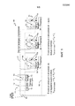
Фиг.1 - примерная система обнаружения дугового пробоя для множества оконечных устройств, например, электрических розеток.Figure 1 is an exemplary arc breakdown detection system for a variety of terminal devices, for example, electrical outlets.
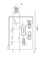
Фиг.2 - блок-схема примерных компонентов оконечного устройства, показанного на фиг.1, например, электрической розетки, в соответствии с одним вариантом осуществления.FIG. 2 is a block diagram of exemplary components of a terminal device shown in FIG. 1, for example, an electrical outlet, in accordance with one embodiment.
Фиг.3 - блок-схема примерных компонентов прерывателя цепи, показанного на фиг.1, в соответствии с одним вариантом осуществления.FIG. 3 is a block diagram of exemplary components of a circuit breaker shown in FIG. 1, in accordance with one embodiment.
Фиг.4 - примерная принципиальная схема, показывающая местоположение последовательного дугового пробоя, обнаруживаемого прерывателем цепи, показанным на фиг.1.FIG. 4 is an exemplary circuit diagram showing the location of a sequential arc breakdown detected by a circuit breaker shown in FIG. 1.
Фиг.5 - примерная принципиальная схема, показывающая местоположение параллельного дугового пробоя, обнаруживаемого прерывателем цепи, показанным на фиг.1.FIG. 5 is an exemplary circuit diagram showing a location of a parallel arc breakdown detected by a circuit breaker shown in FIG. 1.
Фиг.6 - блок-схема последовательности операций примерного способа управления, выполняемого контроллером системы защиты от дугового пробоя, показанной на фиг.1, для обнаружения дугового пробоя в ответвленной цепи, в соответствии с раскрытым вариантом осуществления.FIG. 6 is a flowchart of an exemplary control method performed by the controller of the arcing protection system of FIG. 1 for detecting arcing in a branch circuit, in accordance with the disclosed embodiment.
Фиг.7 - блок-схема последовательности операций примерного способа управления, выполняемого контроллером системы защиты от дугового пробоя, показанного на фиг.1, для обнаружения последовательного дугового пробоя в ответвленной цепи, в соответствии с дополнительным раскрытым вариантом осуществления.FIG. 7 is a flowchart of an exemplary control method performed by the controller of the arcing protection system of FIG. 1 for detecting a sequential arcing fault in a branch circuit, in accordance with a further disclosed embodiment.
Фиг.8 - блок-схема последовательности операций примерного способа управления, выполняемого контроллером системы защиты от дугового пробоя, показанного на фиг.1, для обнаружения параллельного дугового пробоя в ответвленной цепи, в соответствии с другим раскрытым вариантом осуществления.FIG. 8 is a flowchart of an exemplary control method performed by the controller of the arcing protection system of FIG. 1 for detecting parallel arcing in a branch circuit in accordance with another disclosed embodiment.
ПОДРОБНОЕ ОПИСАНИЕDETAILED DESCRIPTION
Фиг.1 изображает примерную систему 100 обнаружения дугового пробоя, которая включает в себя прерыватель цепи 110, множество оконечных устройств 150, расположенных ниже по потоку, например, электрических розеток A, B и C, подсоединенных электропроводкой ответвления ответвленной цепи. Система 100 включает в себя источник 102 питания переменного тока, который может быть обычной 200-А линией питания для здания, например, жилого здания. Линейный провод 104, который может служить электропроводкой ответвления, которая соединяет источник 102 питания переменного тока с прерывателем цепи 110 и оконечными устройствами 150. Нейтральный провод 106 также соединяет источник 102 питания переменного тока с прерывателем цепи 110 и оконечными устройствами 150. Линия 108 заземления также соединяет прерыватель цепи 110 с оконечным устройством 150. Понятно, что прерыватель цепи 110 применяется для защиты от коротких замыканий и других ситуаций перегрузки из-за оконечного устройства 150 посредством прерывания подачи питания в оконечные устройства 150 в случае аномальной ситуации, например, например, чрезмерного тока.Figure 1 depicts an exemplary arc
Каждое из оконечных устройств 150 включает в себя контроллер 160 для управления компонентами и действиями оконечного устройства, датчик 152 тока со стороны нагрузки и датчик 154 напряжения со стороны нагрузки. Датчик 152 тока со стороны нагрузки присоединен с возможностью измерения тока в линейном проводе 104 и представления выходного сигнала, характеризующего измеренный ток в линейном проводе 104, в контроллер 160. Датчик 154 напряжения присоединен между линейным проводом 104 и нейтральным проводом 106 для обеспечения напряжения между линейным и нейтральным проводниками 104 и 106, соответственно. Датчик 154 напряжения представляет выходной сигнал, характеризующий измеренное напряжение между линейным проводом 104 и нейтральным проводом 106, в контроллер 160. Как показано на фиг.2, оконечное устройство 110 может также включать в себя память 162 и интерфейс(ы) 164 связи (например, схемы связи) для осуществления связи с другими удаленными устройствами, например, прерывателем цепи 110. Память 162 может хранить данные или исполняемый компьютером код. Контроллер 160 может передавать информацию, например, измеренные ток или напряжение в/на оконечном устройстве 150, в прерыватель цепи 110 через интерфейс 164 связи. Оконечное устройство 150 может осуществлять связь через интерфейс 164 связи, с использованием коммуникационного протокола для осуществления беспроводной, проводной связи или связи по линии питания.Each of the
В приведенном примере оконечные устройства 150 включают в себя обычные трехконтактные розетки 156 электропитания, которые обеспечивают питание, когда подсоединено (включено в розетку) нагрузочное устройство. Однако, оконечные устройства 150 могут включать в себя другие электрические устройства, кроме электрических розеток, например, электрические переключатели (например, переключатели освещения), электрические разъемы, устройства освещения и т.п.In the example shown,
Как также показано на фиг.1, прерыватель цепи 110 включает в себя возможность обнаружения перегрузки по току, а также обнаружение дугового пробоя путем контроля тока или напряжения в начальной точке ответвления с помощью датчика(ов) со стороны питания и на каждом оконечном устройстве с помощью датчика(ов) со стороны нагрузки, как поясняется ниже. Прерыватель цепи 110 включает в себя контроллер 118 отключения, контроллер 120 для управления компонентами и действиями прерывателя цепи 110 и датчики со стороны питания, например, датчик 114 тока и датчик 116 напряжения. Контроллер 118 отключения управляет размыкающим механизмом 112 (называемым также «прерывателем цепи»), который, при включении, прерывает поток мощности в линейный провод 104. Размыкающий механизм 112 может представлять собой реле, через которое передается мощность, когда реле замкнуто, и которое прерывает питание, когда реле разомкнуто. Разумеется, можно применить другие размыкающие механизмы. Как показано на фиг.3, прерыватель цепи 110 может также включать в себя память 122 и интерфейс(ы) 124 связи (например, схемы связи) для осуществления связи с другими удаленными устройствами, например, оконечными устройствами 150. Память 122 может хранить данные или исполняемый компьютером код. Контроллер 120 может управлять связью через интерфейс 124 связи, с каждым из оконечных устройств 150, для приема измеренного тока или напряжения в оконечных устройствах 150. Прерыватель цепи 110 может осуществлять беспроводную, проводную связь или связь по линии питания с каждым из оконечных устройств 150 через интерфейс 124 связи.As also shown in FIG. 1, the
Датчик 114 тока подсоединен с возможностью определения тока в линейном проводе 104 и представления выходного сигнала, характеризующего снятый ток в линейном проводе 104 начальной точке ответвления, в контроллер 120. Датчик 116 напряжения присоединен между линейным проводом 104 и нейтральным проводом 106 для обеспечения напряжения между линейным и нейтральным проводниками 104 и 106, соответственно. Датчик 116 напряжения представляет выходной сигнал, характеризующий измеренное напряжение между линейным проводом 104 и нейтральным проводом 106 в начальной точке ответвления, в контроллер 160. Контроллер 120 оценивает измеренные ток или напряжение в начальной точке ответвления и в каждом из оконечных устройств 150, чтобы определять, существуют ли неравномерности напряжения или тока, и управляет контроллером 118 отключения для запуска размыкающего механизма 112, когда обнаруживается аномальной состояние, например, состояние дугового пробоя.The
Как поясняется ниже со ссылкой на фиг.4 и 5, прерыватель цепи 110 обеспечивает обнаружение дугового пробоя и защиту от состояния последовательного дугового пробоя и состояния параллельного дугового пробоя, соответственно. Фиг.4 является примерной принципиальной схемой, показывающей местоположение репрезентативного последовательного дугового пробоя 402, обнаруженного системой 100 защиты от дугового пробоя. Последовательный дуговой пробой 402 может происходить, когда дуга имеет место либо на линейном проводе 120, либо на нейтральном проводе 122.As explained below with reference to FIGS. 4 and 5, the
Для защиты от последовательного дугового пробоя, контроллер 120 получает результаты измерения напряжения в начальной точке ответвления и на каждом из оконечных устройств 150 (например, электрических розеток A, B и C), вычисляет падение напряжения в секции электропроводки ответвления (или «ответвительной проводной секции») 104, 106 ответвленной цепи для каждого оконечного устройства 150 и сравнивает каждое из падений напряжения с порогом падения напряжения, например, допустимым напряжением ответвленной цепи. Падение напряжения в секции электропроводки ответвления для оконечного устройства является разностью между результатом измерения напряжения в начальной точке ответвления и результатом измерения напряжения со стороны нагрузки на оконечном устройстве. Порог падения напряжения может быть фиксированным порогом или переменным порогом, основанным на токе нагрузки, измеряемым в ответвленной цепи. Например, порог может изменяться непосредственно с током нагрузки, например, порог может повышаться для уменьшения чувствительности системы при повышенных токах нагрузки.To protect against consecutive arc breakdown, the
Если каждое из падений напряжения находится в пределах допустимого напряжения (например, V ответвленной цепи ≈ VA ≈ VB ≈ VC), то последовательный дуговой пробой отсутствует. В ином случае, если какое-то из падений напряжения превышает допустимое напряжение, то импеданс цепи является слишком большим и, следовательно, контроллером 120 обнаруживается последовательный дуговой пробой. Например, как показано на фиг.4, падение напряжения в секции электропроводки ответвления для каждого из оконечных устройств 150, например, электрическим розеткам B и C, превышает допустимое напряжение (например, Vпрерывателя цепи >> VB или VC), отражая наличие большого импеданса в ответвленной цепи, в результате последовательного дугового пробоя 402. Если последовательный дуговой пробой присутствует, например, последовательный дуговой пробой 402, то контроллер 120 вынуждает размыкающий механизм 112 разомкнуться посредством контроллера 118 отключения.If each of the voltage drops is within the permissible voltage (for example, V of the branch circuit ≈ V A ≈ V B ≈ V C ), then there is no consecutive arc breakdown. Otherwise, if any of the voltage drops exceeds the permissible voltage, then the circuit impedance is too large and, therefore, a sequential arc breakdown is detected by the
Фиг.5 является примерной принципиальной схемой, показывающей местоположение репрезентативного параллельного дугового пробоя 502, обнаруженного системой 100 защиты от дугового пробоя. Параллельный дуговой пробой 502 может возникать, когда дуга образуется между линейным проводом 104 и нейтральным проводом 106. Такая дуга создает сопротивление посредством обеспечения пути для тока между линейным проводом 104 и нейтральным проводом 106.5 is an exemplary circuit diagram showing a location of a representative
Для обнаружения параллельного дугового пробоя, контроллер 120 получает результаты измерения тока в начальной точке ответвления и в каждом из оконечных устройств 150 (например, электрических розеток A, B и C) и вычисляет разностный ток между результатом измерения тока в начальной точке ответвления и суммирует измерения тока со стороны нагрузки для каждого оконечного устройства 150. Затем контроллер 120 сравнивает разностный ток с порогом разности токов, например, допустимым током ответвленной цепи. Если разность токов находится в пределах допустимого тока (например, I ответвленной цепи ≈ IA+IB+IC), то параллельный дуговой пробой отсутствует. В противном случае, если вычисленная разность токов превышает допустимый ток, то контроллером 120 обнаруживается параллельный дуговой пробой. Например, как показано на фиг.5, разностный ток превышает допустимый ток (например, I ответвленной цепи > IA+IB+IC), отражая, тем самым, наличие большого сопротивления в ответвленной цепи в результате параллельного дугового пробоя 502. Если параллельный дуговой пробой, например, параллельный дуговой пробой 502, присутствует, то контроллер 120 вынуждает размыкающий механизм 112 разомкнуться посредством контроллера 118 отключения.To detect parallel arc faults, the
Преимущества системы 100 включают в себя выполнение обнаружения пробоя в электропроводке ответвления ответвленной цепи, при исключении использования вероятностных алгоритмов обнаружения, поскольку определительный результат измерения напряжения или тока в начальной точке ответвления и на каждом оконечном устройстве представляется в прерыватель цепи 110. В системе 100, централизованная система управления, например, контроллер 110, собирает каждое из измеренных состояний в начальной точке и на каждом оконечном устройстве и определяет наличие состояния дугового пробоя, если таковое вообще имеет место, в ответвленной цепи по оценке измеренных состояний. Система может изолировать дуговой пробой между двумя элементами ответвления и определять секцию электропроводки ответвления, в которой происходит дуговой пробой. Система 100 обеспечивает, в результате, более совершенное обнаружение дугового пробоя, с более надежным исключением ненужных размыканий, чем вероятностный алгоритм обнаружения. Система может быть встроена в приложения «эффективных домов» или применяться как средство для поиска неисправностей для информирования пользователя о местоположениях дуговых пробоев. Кроме того, энергия, отбираемая на один элемент ответвления в ответвленной цепи, также может контролироваться датчиками в системах.The advantages of
Контроллеры, представленные в настоящей заявке, например, контроллеры 120 и 160, могут представлять собой микропроцессор, процессор, специализированную интегральную схему (ASIC), программируемый логический контроллер (PLC), программируемое логическое устройство (PLD), логическое устройство с эксплуатационным программированием (FPLD), эксплуатационно программируемую вентильную матрицу (FPGA), дискретную логику и т.п. или любое другое аналогичное устройство. Контроллеры 120 и 160 может включать в себя память (не показанную) или получать доступ к внешней памяти (например, 122 или 162), которая может включать в себя аппаратное обеспечение, микропрограммное обеспечение или материальный машиночитаемый носитель для хранения данных, который хранит команды и данные для выполнения операций, описанных в настоящей заявке. Машиночитаемый носитель для хранения данных включает в себя любой механизм, который хранит информацию и представляет информацию в машиночитаемой форме. Например, машиночитаемый носитель для хранения данных включает в себя постоянную память (ROM), оперативную память (RAM), носитель на магнитных дисках для хранения данных, оптический носитель для хранения данных, флэш-память и т.п.The controllers presented in this application, for example,
Работа различных примерных алгоритмов принятия решений обнаружения и защиты от дугового пробоя описана ниже со ссылкой на фиг.1, 4 и 5 в связи блок-схемами последовательностей операций, показанными на фиг.6-8. Блок-схемы последовательностей операций на фиг.6-8 характеризуют примерные машиночитаемые команды для выполнения вышеописанных способов для обнаружения и защиты от дуговых пробоев. В данном примере машиночитаемые команды содержат алгоритмы для выполнения: (a) процессором, (b) контроллером или (c) одним или более другими подходящими устройствами обработки данных. Алгоритмы могут быть реализованы в программном обеспечении, хранящемся на материальном носителе, например, во флэш-памяти, на компакт-диске, гибком диске, жестком дисководе, цифровом видео (универсальном) диске (DVD) или в других запоминающих устройствах, но специалисты со средним уровнем компетентности в данной области техники без труда поймут, что весь алгоритм и/или его части могут, в качестве альтернативы, выполняться другим устройством, кроме процессора и/или могут быть реализованы в микропрограммном обеспечении или специализированном аппаратном обеспечения общеизвестным способом (например, алгоритм может быть реализован специализированной интегральной схемой (ASIC), программируемым логическим устройством (PLD), логическим устройством с эксплуатационным программированием (FPLD), эксплуатационно программируемой вентильной матрицей (FPGA), дискретной логикой и т.п.). Например, любой или все компоненты контроллеров, например, контроллеров 120 и 160, в системе 100 на фиг.1 могут быть реализованы посредством программного обеспечения, аппаратного обеспечения и/или микропрограммного обеспечения. Кроме того, хотя примерные алгоритмы описаны со ссылкой на блок-схемы последовательностей операций, изображенные на фиг.6-8, специалисты со средним уровнем компетентности в данной области техники без труда поймут, что, в качестве альтернативы, можно воспользоваться другими способами реализации примерных машиночитаемых команд. Например, можно изменять последовательность выполнения блоков, и/или можно изменять, исключать или объединять некоторые из описанных блоков.The operation of various exemplary decision-making algorithms for detecting and protecting against arc faults is described below with reference to FIGS. 1, 4 and 5 in connection with the flowcharts shown in FIGS. 6-8. The flowcharts of FIGS. 6-8 describe exemplary computer-readable instructions for performing the above methods for detecting and protecting against arc breakdowns. In this example, machine-readable instructions comprise algorithms for executing: (a) a processor, (b) a controller, or (c) one or more other suitable data processing devices. Algorithms can be implemented in software stored on tangible media, for example, flash memory, a CD, a floppy disk, a hard disk drive, a digital video (universal) disk (DVD), or other storage devices, but specialists with average the level of competence in the art will easily understand that the entire algorithm and / or its parts can, alternatively, be executed by a device other than the processor and / or can be implemented in firmware or specialized in hardware in a well-known way (for example, an algorithm can be implemented by a specialized integrated circuit (ASIC), programmable logic device (PLD), logic device with operational programming (FPLD), field programmable gate array (FPGA), discrete logic, etc.) . For example, any or all of the components of the controllers, for example, the
На фиг.6 показана блок-схема последовательности операций примерного способа 600 управления, выполняемого контроллером (например, контроллером 120) в системе 100 защиты от дугового пробоя, показанной на фиг.1, для обнаружения дугового пробоя в ответвленной цепи, в соответствии с раскрытым вариантом осуществления.FIG. 6 is a flowchart of an
На этапе 602 контроллер 120 инициирует процедуру обнаружения дугового пробоя. На этапе 604 контроллер 120 принимает результат измерения напряжения или тока в ответвленной цепи, полученного датчиком(ами) со стороны питания (например, датчиком 114 тока или датчиком 116 напряжения) в начальной точке ответвления со стороны питания от всех оконечных устройств 150. На этапе 606 контроллер 120 принимает результат измерения напряжения или тока со стороны нагрузки на/в каждом оконечном устройстве 150, измеренный(е) соответствующим(и) датчиком(ами), расположенным(и) со стороны нагрузки (например, датчиком 152 тока или датчиком 154 напряжения). На этапе 608 контроллер 120 сравнивает результат измерения напряжения или тока в начальной точке ответвления с результатами измерения напряжения или тока со стороны нагрузки на/в оконечных устройствах 150.At 602, the
На этапе 610 контроллер 120 обнаруживает на основании сравнения, существует ли состояние дугового пробоя. Например, контроллер 120 определяет на основании сравнения, существуют ли неравномерности напряжения или тока на/в каждом оконечном устройстве 150 относительно напряжения или тока в начальной точке ответвления. В отсутствие неравномерности, способ 600 возвращается на этап 604. В противном случае, на этапе 612, если обнаружено состояние дугового пробоя, контроллер 120 выдает сигнал отключения для размыкания прерывателя цепи 110, посредством контроллера 118 отключения и размыкающего механизма 112.At
На Фиг.7 представлена блок-схема последовательности операций примерного способа 700 управления, выполняемого контроллером (например, контроллером 120) в системе 100 защиты от дугового пробоя, показанной на фиг.1, для обнаружения последовательного дугового пробоя в ответвленной цепи, с соответствии с раскрытым вариантом осуществления.FIG. 7 is a flowchart of an
На этапе 702 контроллер 120 инициирует процедуру обнаружения последовательного дугового пробоя. На этапе 704 контроллер 120 принимает результат измерения напряжения в ответвленной цепи, полученного датчиком(ами) со стороны питания (например, датчиком 116 напряжения) в начальной точке ответвления со стороны питания от всех оконечных устройств 150. На этапе 706 контроллер 120 принимает результат измерения напряжения со стороны нагрузки на каждом оконечном устройстве 150, измеренный соответствующим(и) датчиком(ами) (например, датчиком 154 напряжения). На этапе 708 контроллер 120 определяет падение напряжения в секции электропроводки ответвления для каждого оконечного устройства 150. Например, падение напряжения в секции электропроводки ответвления для оконечного устройства равно разности между результатом измерения напряжения в начальной точке ответвления и результатом измерения напряжения со стороны нагрузки на оконечном устройстве.At 702, the
На этапе 710 контроллер 120 сравнивает найденные падения напряжений с порогом падения напряжения (например, допустимым напряжением или стандартным отклонением для ответвленной цепи). Порог падения напряжения может быть фиксированным порогом или переменным порогом, основанным на токе нагрузки, измеряемым в ответвленной цепи. Например, порог может изменяться непосредственно с током нагрузки, например, порог может повышаться для уменьшения чувствительности системы при повышенных токах нагрузки. На этапе 712 контроллер 120 определяет на основании сравнения, существует ли состояние последовательного дугового пробоя. Например, если падение напряжения в секции электропроводки ответвления для любого из оконечных устройств 150 (например, разность между напряжениями в начальной точке ответвления и в электрической розетке A, в начальной точке ответвления и в электрической розетке B и в начальной точке ответвления и в электрической розетке C) находится в пределах допуска для ответвленной цепи, то напряжения в начальной точке ответвления (VПрерывателя цепи), в электрической розетке A (VA), в электрической розетке B (VB) и в электрической розетке C (VC) равны или приблизительно равны, как показано на фиг.1 (поясняется выше). В данном случае, в ответвленной цепи отсутствует последовательный дуговой пробой, поэтому способ 700 возвращается на этап 704.At
Однако, если падение напряжения в секции электропроводки ответвления для любого из оконечных устройств 150 превышает допустимое напряжение для секции ответвления, то контроллер 120 определяет последовательный дуговой пробой в секции ответвления. Например, если любое из напряжений на оконечных устройствах 150, например, VA, VB и VC, превышает напряжение в начальной точке цепи (VПрерывателя цепи), то имеет место последовательный дуговой пробой, например, последовательный дуговой пробой 402, как показано на фиг.4. В данном случае контроллер 120 выдает сигнал отключения для размыкания прерывателя цепи 110 посредством контроллера 118 отключения и размыкающего механизма 112, на этапе 714.However, if the voltage drop in the branch wiring section for any of the
На Фиг.8 представлена блок-схема последовательности операций примерного способа 800 управления, выполняемого контроллером (например, контроллером 120) в системе 100 защиты от дугового пробоя, показанной на фиг.1, для обнаружения параллельного дугового пробоя в ответвленной цепи, с соответствии с раскрытым вариантом осуществления.FIG. 8 is a flowchart of an
На этапе 802 контроллер 120 инициирует процедуру обнаружения параллельного дугового пробоя. На этапе 804 контроллер 120 принимает результат измерения тока ответвленной цепи, полученного датчиком(ами) со стороны питания (например, датчиком 114 тока) в начальной точке ответвления со стороны питания от всех оконечных устройств 150. На этапе 806 контроллер 120 принимает результат измерения тока со стороны нагрузки на каждом оконечном устройстве 150, измеренный соответствующим(и) датчиком(ами) (например, датчиком 152 напряжения). На этапе 808 контроллер 120 определяет разность токов в ответвленной цепи. Например, контроллер определяет разность между результатом измерения тока в начальной точке ответвления и суммой всех результатов измерения токов со стороны нагрузки в каждом оконечном устройстве 150.At 802,
На этапе 810 контроллер 120 сравнивает разность токов с порогом разности токов (например, допустимым током или стандартным отклонением для ответвленной цепи). Например, если разность токов равна нулю или находится в пределах допуска для ответвленной цепи, то ток в начальной точке ответвления (IПрерывателя цепи) равен или приблизительно равен сумме токов каждого из оконечных устройств 150 (например, IA+IB+IC), как показано на фиг.1. В данном случае, в ответвленной цепи отсутствует параллельный дуговой пробой, поэтому способ 800 возвращается на этап 804.At
Однако, если разность токов превышает допустимый ток для ответвленной цепи, то контроллер 120 определяет параллельный дуговой пробой в ответвленной цепи. Например, если ток в начальной точке ответвления (IПрерывателя цепи) превышает сумму токов оконечных устройств 150 (например, IA+IB+IC), то имеет место параллельный дуговой пробой, например, параллельный дуговой пробой 502, как показано на фиг.5. В данном случае, на этапе 814 контроллер 120 выдает сигнал отключения для размыкания прерывателя цепи 110, посредством контроллера 118 отключения и размыкающего механизма 112.However, if the current difference exceeds the permissible current for the branch circuit, then the
Хотя выше показаны и описаны конкретные варианты осуществления и применения настоящего изобретения, следует понимать, что настоящее изобретение не ограничено в точности конструкцией и комбинациями, раскрытыми в настоящей заявке, и что на основе вышеприведенных описаний можно выявить различные модификации, изменения и варианты, не выходящие за пределы существа и объема изобретения, определенных в прилагаемой формуле изобретения.Although specific embodiments and applications of the present invention are shown and described above, it should be understood that the present invention is not limited in accuracy by the construction and combinations disclosed in this application, and that based on the above descriptions, various modifications, changes and variations are possible without departing from the scope of the essence and scope of the invention defined in the attached claims.
Claims (45)
Applications Claiming Priority (1)
| Application Number | Priority Date | Filing Date | Title |
|---|---|---|---|
| PCT/US2013/062584 WO2015047383A1 (en) | 2013-09-30 | 2013-09-30 | Distributed arc fault protection between outlet and circuit breaker |
Publications (2)
| Publication Number | Publication Date |
|---|---|
| RU2016105243A RU2016105243A (en) | 2017-11-13 |
| RU2654046C2 true RU2654046C2 (en) | 2018-05-16 |
Family
ID=52744260
Family Applications (1)
| Application Number | Title | Priority Date | Filing Date |
|---|---|---|---|
| RU2016105243A RU2654046C2 (en) | 2013-09-30 | 2013-09-30 | Distributed arc fault protection between outlet and circuit breaker |
Country Status (8)
| Country | Link |
|---|---|
| US (1) | US10181714B2 (en) |
| EP (1) | EP3053235A4 (en) |
| CN (1) | CN105580232B (en) |
| AU (1) | AU2013401941B2 (en) |
| CA (1) | CA2921338C (en) |
| MX (1) | MX356122B (en) |
| RU (1) | RU2654046C2 (en) |
| WO (1) | WO2015047383A1 (en) |
Cited By (4)
| Publication number | Priority date | Publication date | Assignee | Title |
|---|---|---|---|---|
| RU199233U1 (en) * | 2020-04-17 | 2020-08-24 | Общество с ограниченной ответственностью "Эколайт" (ООО "Эколайт") | ARC BREAKDOWN PROTECTION DEVICE |
| RU200084U1 (en) * | 2020-05-22 | 2020-10-05 | Федеральное государственное бюджетное образовательное учреждение высшего образования "Казанский государственный энергетический университет" | Device for testing arc fault and spark gaps protection devices |
| RU2737951C1 (en) * | 2020-06-03 | 2020-12-07 | Владимир Семенович Мельников | Electrical installation control and protection system |
| RU2739576C1 (en) * | 2020-05-22 | 2020-12-28 | Федеральное государственное бюджетное образовательное учреждение высшего образования "Казанский государственный энергетический университет" | Method of checkout of arc-breakdown protection and spark gaps |
Families Citing this family (24)
| Publication number | Priority date | Publication date | Assignee | Title |
|---|---|---|---|---|
| US9659721B1 (en) | 2014-05-06 | 2017-05-23 | Google Inc. | Circuit breakers with integrated safety, control, monitoring, and protection features |
| WO2016137424A1 (en) * | 2015-02-23 | 2016-09-01 | Ge Aviation Systems Llc | Method and apparatus for an electrical fault detecting system for a cable |
| US9966206B1 (en) * | 2015-05-06 | 2018-05-08 | Google Llc | Circuit breakers with integrated safety, control, monitoring, and protection features |
| DE102015115284B3 (en) * | 2015-09-10 | 2016-11-24 | Hamburg Innovation Gmbh | Protective device for an electrical power supply device and electrical power supply device with such a protective device |
| DE102016106798A1 (en) * | 2016-04-13 | 2017-10-19 | R. Stahl Schaltgeräte GmbH | Module for providing an intrinsically safe electrical output cable and explosion-proof luminaire |
| CN107370123B (en) * | 2016-05-13 | 2019-02-26 | 上海电科电器科技有限公司 | Arc fault detection device |
| EP3443626B1 (en) | 2016-05-31 | 2023-10-25 | Siemens Aktiengesellschaft | Arc fault identification unit |
| US11205891B2 (en) | 2016-05-31 | 2021-12-21 | Siemens Aktiengesellschaft | Arc fault detection unit |
| WO2017207031A1 (en) * | 2016-05-31 | 2017-12-07 | Siemens Aktiengesellschaft | Arcing fault recognition unit |
| WO2018032652A1 (en) * | 2016-08-19 | 2018-02-22 | 广东美的制冷设备有限公司 | Household appliance, and arc fault detection device and method therefor |
| DE102016219849A1 (en) * | 2016-10-12 | 2018-04-12 | Robert Bosch Gmbh | Device and method for detecting an arc fault and energy supply with a device for detecting an arc fault |
| US10741348B2 (en) * | 2017-03-30 | 2020-08-11 | Richtek Technology Corporation | Power transmission apparatus |
| FR3068138B1 (en) * | 2017-06-22 | 2019-07-19 | Schneider Electric Industries Sas | DEVICE AND METHOD FOR TESTING THE OPERATION OF A PROTECTIVE APPARATUS AND PROTECTIVE APPARATUS COMPRISING SUCH A DEVICE FOR TESTING |
| GB2571551B (en) * | 2018-03-01 | 2021-03-03 | Ge Aviat Systems Ltd | System and method for detecting arc faults |
| CN108899869B (en) * | 2018-05-15 | 2020-04-03 | 广东美的制冷设备有限公司 | Fault arc protection circuit |
| US10601213B2 (en) * | 2018-05-22 | 2020-03-24 | Schneider Electric USA, Inc. | Arc fault detection using frequency hopping techniques |
| US11251602B2 (en) | 2018-07-09 | 2022-02-15 | Schneider Electric Industries Sas | Method for locating an electrical arc fault and electrical installation protection device implementing such a method |
| CN110579681B (en) * | 2019-08-09 | 2021-09-21 | 江苏方天电力技术有限公司 | Distribution network fault arc detection device |
| DE102019214318B4 (en) | 2019-09-20 | 2022-11-10 | Siemens Aktiengesellschaft | protection switching system |
| DE102019214682B4 (en) * | 2019-09-25 | 2021-07-08 | Fraunhofer-Gesellschaft zur Förderung der angewandten Forschung e.V. | Method for protecting at least part of a network segment of an electrical energy distribution network and network segment of an electrical energy distribution network |
| JP2021081398A (en) * | 2019-11-22 | 2021-05-27 | パナソニックIpマネジメント株式会社 | Abnormality detection system, distribution board, abnormality detection method, and program |
| US20230393218A1 (en) | 2020-10-29 | 2023-12-07 | Panasonic Intellectual Property Management Co., Ltd. | Arc detection system, arc detection method, and recording medium |
| US11698403B2 (en) * | 2020-12-17 | 2023-07-11 | Schneider Electric USA, Inc. | Residential fault diagnostic tool |
| US20230197391A1 (en) * | 2021-12-22 | 2023-06-22 | Schneider Electric USA, Inc. | Arc flash detection method |
Citations (5)
| Publication number | Priority date | Publication date | Assignee | Title |
|---|---|---|---|---|
| RU2311699C2 (en) * | 2005-03-02 | 2007-11-27 | Открытое акционерное общество "Всероссийский научно-исследовательский проектно-конструкторский и технологический институт релестроения с опытным производством" | Method and device for protecting power distribution networks against arcing short circuits |
| US20070279068A1 (en) * | 2006-05-31 | 2007-12-06 | Harres Daniel N | Power diagnostic system and method |
| US20080129307A1 (en) * | 2006-11-30 | 2008-06-05 | Honeywell International Inc. | Differential arc fault detection |
| GB2449677A (en) * | 2007-06-01 | 2008-12-03 | Kevin Jones | A system for identifying a risk of fire in a power network |
| RU2484487C2 (en) * | 2004-10-01 | 2013-06-10 | Эрбюс Операсьон (Сас) | Method and device for determination of electric arc occurrence on at least one electric cable |
Family Cites Families (48)
| Publication number | Priority date | Publication date | Assignee | Title |
|---|---|---|---|---|
| US4870529A (en) | 1986-10-31 | 1989-09-26 | Displaytek, Inc. | Active arc protection circuit |
| GB8727490D0 (en) | 1987-11-24 | 1987-12-23 | Nat Res Dev | Detecting faults in transmission circuits |
| US6292337B1 (en) | 1993-08-05 | 2001-09-18 | Technology Research Corporation | Electrical system with arc protection |
| US5650773A (en) | 1995-05-05 | 1997-07-22 | Chiarello; Frank Anthony | Multi-functional intrusion warning system for branch circuits of a home and the like |
| US5973896A (en) | 1995-05-26 | 1999-10-26 | David C. Nemir | Shock and arc protection device for an electrical distribution system |
| FR2749084B3 (en) | 1996-05-22 | 1998-06-26 | Excem | METHOD AND DEVICE FOR DETECTING SERIAL DEFECTS IN AN ELECTRICAL PANEL |
| DE19612216A1 (en) | 1996-03-27 | 1997-10-02 | Siemens Ag | Electronic branch switching device |
| US6014297A (en) | 1997-09-29 | 2000-01-11 | Eaton Corporation | Apparatus for detecting arcing faults and ground faults in multiwire branch electric power circuits |
| US5986860A (en) | 1998-02-19 | 1999-11-16 | Square D Company | Zone arc fault detection |
| US5896262A (en) | 1998-02-26 | 1999-04-20 | Eaton Corporation | Arc fault detector with protection against nuisance trips and circuit breaker incorporating same |
| US6144537A (en) | 1998-07-10 | 2000-11-07 | Hubbell Incorporated | Arcing fault and ground fault interrupting device for branch circuits and extensions |
| US20040136125A1 (en) | 1998-09-16 | 2004-07-15 | Nemir David C. | Leakage current detection based upon load sharing conductors |
| US6084756A (en) | 1999-01-22 | 2000-07-04 | Eaton Corporation | Apparatus for testing protection of an electric power distribution circuit by an arc fault circuit breaker |
| US6504692B1 (en) | 2000-04-06 | 2003-01-07 | Pass & Seymour, Inc. | AFCI device which detects upstream and downstream series and parallel ARC faults |
| US6987389B1 (en) | 2000-11-14 | 2006-01-17 | Pass & Seymour, Inc. | Upstream/downstream arc fault discriminator |
| JP4894087B2 (en) | 2001-02-20 | 2012-03-07 | パナソニック株式会社 | Private branch exchange |
| ES2217108T3 (en) | 2001-08-10 | 2004-11-01 | Abb Schweiz Ag | ELECTRICAL COMPONENT PROTECTED AGAINST DISTURBISHING LIGHT ARCHES. |
| US20030156367A1 (en) | 2002-02-01 | 2003-08-21 | Macbeth Bruce F. | Arc fault circuit interrupter with upstream impedance detector |
| US7180717B2 (en) * | 2002-07-12 | 2007-02-20 | Cooper Technologies Company | Electrical network protection system |
| US7253640B2 (en) | 2003-01-13 | 2007-08-07 | Eaton Corporation | Arc fault detector and method for locating an arc fault |
| CN2651991Y (en) | 2003-07-17 | 2004-10-27 | 黄华道 | Socket with electric arc and leakage protective function |
| US7068045B2 (en) | 2003-07-25 | 2006-06-27 | Gaton Corporation | Apparatus and method for real time determination of arc fault energy, location and type |
| US6943558B2 (en) * | 2003-09-15 | 2005-09-13 | The Boeing Company | System and method for remotely detecting electric arc events in a power system |
| ATE514218T1 (en) | 2004-03-04 | 2011-07-15 | Siemens Ag | PROTECTIVE DEVICE FOR A CONSUMER BRANCH |
| US7057401B2 (en) | 2004-03-23 | 2006-06-06 | Pass & Seymour, Inc. | Electrical wiring inspection system |
| US7362552B2 (en) | 2004-07-20 | 2008-04-22 | Eaton Corporation | Arc fault circuit interrupter |
| US20060092585A1 (en) | 2004-11-04 | 2006-05-04 | Chan Peter O | Electrical supply system with arc protection |
| US7453267B2 (en) | 2005-01-14 | 2008-11-18 | Power Measurement Ltd. | Branch circuit monitor system |
| US7362553B2 (en) | 2005-06-08 | 2008-04-22 | Eaton Corporation | Arc fault circuit interrupter and method for inhibiting series arc protection based on dimmer phase angle |
| US7359168B2 (en) | 2005-10-18 | 2008-04-15 | Eaton Corporation | Arc fault circuit interrupter and method for disabling series arc protection during current transients |
| US7796366B2 (en) | 2005-12-09 | 2010-09-14 | Hamilton Sundstrand Corporation | AC arc fault detection and protection |
| CN101379671B (en) | 2006-02-06 | 2012-04-25 | 施恩禧电气有限公司 | Coordinated fault protection system |
| US7282924B1 (en) | 2006-06-29 | 2007-10-16 | Target Hi-Tech Electronics Ltd. | Computerized electricity system having an arc fault detecting sub-system |
| US7598751B2 (en) | 2006-08-14 | 2009-10-06 | Clemson University Research Foundation | Impedance-based arc fault determination device (IADD) and method |
| US7791346B2 (en) | 2006-10-07 | 2010-09-07 | Ko Instruments, Inc. | Device and method for testing an electrical power branch circuit |
| US7864492B2 (en) * | 2006-10-31 | 2011-01-04 | Siemens Industry, Inc. | Systems and methods for arc fault detection |
| US7463465B2 (en) | 2006-12-28 | 2008-12-09 | General Electric Company | Series arc fault current interrupters and methods |
| US7526393B2 (en) | 2007-09-25 | 2009-04-28 | Thurmond M Jason | Virtual branch load management |
| US7697248B2 (en) | 2007-12-14 | 2010-04-13 | Tomimbang Wendell E | Electrical arc fault circuit interrupter apparatus and method |
| US20090248329A1 (en) * | 2008-03-25 | 2009-10-01 | Siemens Energy & Automation, Inc. | Arc fault root-cause finder system and method |
| US8098465B1 (en) | 2008-03-28 | 2012-01-17 | Reliance Controls Corporation | AFCI breaker providing protection for multiple branch circuits in an electrical panel |
| US7952840B2 (en) | 2008-05-13 | 2011-05-31 | Unitron, L.P. | Receptacle with arc protection circuitry |
| US8233254B2 (en) | 2009-04-10 | 2012-07-31 | Honeywell International, Inc. | Method of ensuring the coordinated arc fault protection in a heirarchial power distribution system |
| US8085055B2 (en) | 2009-04-20 | 2011-12-27 | Veris Industries, Llc | Branch current monitoring system |
| US8405945B2 (en) | 2010-01-14 | 2013-03-26 | International Business Machines Corporation | Power distribution unit branch protection |
| US20120050933A1 (en) | 2010-08-31 | 2012-03-01 | Jian Xu | Branch circuit protection with in-line solid state device |
| US8810253B2 (en) | 2010-09-20 | 2014-08-19 | Thomas L. Marzetta | Characterization of electrical power distribution systems using characterization matrices |
| US8427169B2 (en) | 2010-09-20 | 2013-04-23 | Bertrand M. Hochwald | Noninvasive characterization of electrical power distribution systems |
-
2013
- 2013-09-30 MX MX2016001873A patent/MX356122B/en active IP Right Grant
- 2013-09-30 RU RU2016105243A patent/RU2654046C2/en active
- 2013-09-30 CN CN201380079924.9A patent/CN105580232B/en active Active
- 2013-09-30 WO PCT/US2013/062584 patent/WO2015047383A1/en active Application Filing
- 2013-09-30 US US15/024,571 patent/US10181714B2/en active Active
- 2013-09-30 AU AU2013401941A patent/AU2013401941B2/en active Active
- 2013-09-30 CA CA2921338A patent/CA2921338C/en active Active
- 2013-09-30 EP EP13894733.8A patent/EP3053235A4/en active Pending
Patent Citations (5)
| Publication number | Priority date | Publication date | Assignee | Title |
|---|---|---|---|---|
| RU2484487C2 (en) * | 2004-10-01 | 2013-06-10 | Эрбюс Операсьон (Сас) | Method and device for determination of electric arc occurrence on at least one electric cable |
| RU2311699C2 (en) * | 2005-03-02 | 2007-11-27 | Открытое акционерное общество "Всероссийский научно-исследовательский проектно-конструкторский и технологический институт релестроения с опытным производством" | Method and device for protecting power distribution networks against arcing short circuits |
| US20070279068A1 (en) * | 2006-05-31 | 2007-12-06 | Harres Daniel N | Power diagnostic system and method |
| US20080129307A1 (en) * | 2006-11-30 | 2008-06-05 | Honeywell International Inc. | Differential arc fault detection |
| GB2449677A (en) * | 2007-06-01 | 2008-12-03 | Kevin Jones | A system for identifying a risk of fire in a power network |
Cited By (4)
| Publication number | Priority date | Publication date | Assignee | Title |
|---|---|---|---|---|
| RU199233U1 (en) * | 2020-04-17 | 2020-08-24 | Общество с ограниченной ответственностью "Эколайт" (ООО "Эколайт") | ARC BREAKDOWN PROTECTION DEVICE |
| RU200084U1 (en) * | 2020-05-22 | 2020-10-05 | Федеральное государственное бюджетное образовательное учреждение высшего образования "Казанский государственный энергетический университет" | Device for testing arc fault and spark gaps protection devices |
| RU2739576C1 (en) * | 2020-05-22 | 2020-12-28 | Федеральное государственное бюджетное образовательное учреждение высшего образования "Казанский государственный энергетический университет" | Method of checkout of arc-breakdown protection and spark gaps |
| RU2737951C1 (en) * | 2020-06-03 | 2020-12-07 | Владимир Семенович Мельников | Electrical installation control and protection system |
Also Published As
| Publication number | Publication date |
|---|---|
| AU2013401941B2 (en) | 2019-03-28 |
| WO2015047383A1 (en) | 2015-04-02 |
| US10181714B2 (en) | 2019-01-15 |
| CN105580232B (en) | 2019-07-12 |
| MX2016001873A (en) | 2016-05-24 |
| MX356122B (en) | 2018-05-15 |
| CA2921338A1 (en) | 2015-04-02 |
| CN105580232A (en) | 2016-05-11 |
| US20160241017A1 (en) | 2016-08-18 |
| CA2921338C (en) | 2020-09-15 |
| AU2013401941A1 (en) | 2016-03-03 |
| EP3053235A4 (en) | 2017-06-28 |
| EP3053235A1 (en) | 2016-08-10 |
| RU2016105243A (en) | 2017-11-13 |
Similar Documents
| Publication | Publication Date | Title |
|---|---|---|
| RU2654046C2 (en) | Distributed arc fault protection between outlet and circuit breaker | |
| RU2633518C2 (en) | Method for detecting arc short circuits with application of switched elements in socket | |
| US20210325462A1 (en) | Power distribution systems and methods of testing responses to electrical conditions using a communication network | |
| US20130218359A1 (en) | Power transmission fault analysis system and related method | |
| EP2659561B1 (en) | A method and an apparatus for supervision of current transformer in a differential protection system | |
| US10935609B2 (en) | Methods and systems for ground fault detection in a power distribution system | |
| US10557883B2 (en) | Leakage current detection and protection device for power cord | |
| AU2018204368B2 (en) | Upstream Parallel Arc Fault Outlet Protection Method | |
| US9728955B2 (en) | Zone selective interlocking (ZSI) power distribution operating a ZSI power distribution system | |
| US8737030B2 (en) | Power distribution systems and methods of operating a power distribution system | |
| US8724274B2 (en) | Power distribution systems and methods of operating a power distribution system | |
| US10444725B2 (en) | Power distribution systems and methods of performing zone selective interlocking in power distribution systems with a communication network | |
| KR101019462B1 (en) | Method for determining by detecting inpulse originated from arc | |
| US20230063811A1 (en) | Circuit breakers with notification and reporting capability | |
| US20180241192A1 (en) | Power distribution systems and methods of performing ground fault detection in power distribution systems with a communication network | |
| US11385299B2 (en) | Multiple arc fault/ground fault signal path | |
| CN114646859A (en) | House fault diagnosis tool |