RU2650958C2 - Unit for spreading adhesive onto moving film - Google Patents
Unit for spreading adhesive onto moving film Download PDFInfo
- Publication number
- RU2650958C2 RU2650958C2 RU2015145817A RU2015145817A RU2650958C2 RU 2650958 C2 RU2650958 C2 RU 2650958C2 RU 2015145817 A RU2015145817 A RU 2015145817A RU 2015145817 A RU2015145817 A RU 2015145817A RU 2650958 C2 RU2650958 C2 RU 2650958C2
- Authority
- RU
- Russia
- Prior art keywords
- roller
- applying glue
- movable section
- paragraphs
- contact
- Prior art date
Links
Images


Classifications
-
- B—PERFORMING OPERATIONS; TRANSPORTING
- B05—SPRAYING OR ATOMISING IN GENERAL; APPLYING FLUENT MATERIALS TO SURFACES, IN GENERAL
- B05C—APPARATUS FOR APPLYING FLUENT MATERIALS TO SURFACES, IN GENERAL
- B05C1/00—Apparatus in which liquid or other fluent material is applied to the surface of the work by contact with a member carrying the liquid or other fluent material, e.g. a porous member loaded with a liquid to be applied as a coating
- B05C1/04—Apparatus in which liquid or other fluent material is applied to the surface of the work by contact with a member carrying the liquid or other fluent material, e.g. a porous member loaded with a liquid to be applied as a coating for applying liquid or other fluent material to work of indefinite length
- B05C1/08—Apparatus in which liquid or other fluent material is applied to the surface of the work by contact with a member carrying the liquid or other fluent material, e.g. a porous member loaded with a liquid to be applied as a coating for applying liquid or other fluent material to work of indefinite length using a roller or other rotating member which contacts the work along a generating line
- B05C1/0826—Apparatus in which liquid or other fluent material is applied to the surface of the work by contact with a member carrying the liquid or other fluent material, e.g. a porous member loaded with a liquid to be applied as a coating for applying liquid or other fluent material to work of indefinite length using a roller or other rotating member which contacts the work along a generating line the work being a web or sheets
- B05C1/0834—Apparatus in which liquid or other fluent material is applied to the surface of the work by contact with a member carrying the liquid or other fluent material, e.g. a porous member loaded with a liquid to be applied as a coating for applying liquid or other fluent material to work of indefinite length using a roller or other rotating member which contacts the work along a generating line the work being a web or sheets the coating roller co-operating with other rollers, e.g. dosing, transfer rollers
-
- B—PERFORMING OPERATIONS; TRANSPORTING
- B05—SPRAYING OR ATOMISING IN GENERAL; APPLYING FLUENT MATERIALS TO SURFACES, IN GENERAL
- B05C—APPARATUS FOR APPLYING FLUENT MATERIALS TO SURFACES, IN GENERAL
- B05C1/00—Apparatus in which liquid or other fluent material is applied to the surface of the work by contact with a member carrying the liquid or other fluent material, e.g. a porous member loaded with a liquid to be applied as a coating
- B05C1/04—Apparatus in which liquid or other fluent material is applied to the surface of the work by contact with a member carrying the liquid or other fluent material, e.g. a porous member loaded with a liquid to be applied as a coating for applying liquid or other fluent material to work of indefinite length
- B05C1/08—Apparatus in which liquid or other fluent material is applied to the surface of the work by contact with a member carrying the liquid or other fluent material, e.g. a porous member loaded with a liquid to be applied as a coating for applying liquid or other fluent material to work of indefinite length using a roller or other rotating member which contacts the work along a generating line
- B05C1/0873—Controlling means responsive to conditions of the liquid or other fluent material, of the ambient medium, of the roller or of the work
-
- B—PERFORMING OPERATIONS; TRANSPORTING
- B05—SPRAYING OR ATOMISING IN GENERAL; APPLYING FLUENT MATERIALS TO SURFACES, IN GENERAL
- B05C—APPARATUS FOR APPLYING FLUENT MATERIALS TO SURFACES, IN GENERAL
- B05C1/00—Apparatus in which liquid or other fluent material is applied to the surface of the work by contact with a member carrying the liquid or other fluent material, e.g. a porous member loaded with a liquid to be applied as a coating
- B05C1/04—Apparatus in which liquid or other fluent material is applied to the surface of the work by contact with a member carrying the liquid or other fluent material, e.g. a porous member loaded with a liquid to be applied as a coating for applying liquid or other fluent material to work of indefinite length
- B05C1/08—Apparatus in which liquid or other fluent material is applied to the surface of the work by contact with a member carrying the liquid or other fluent material, e.g. a porous member loaded with a liquid to be applied as a coating for applying liquid or other fluent material to work of indefinite length using a roller or other rotating member which contacts the work along a generating line
- B05C1/12—Apparatus in which liquid or other fluent material is applied to the surface of the work by contact with a member carrying the liquid or other fluent material, e.g. a porous member loaded with a liquid to be applied as a coating for applying liquid or other fluent material to work of indefinite length using a roller or other rotating member which contacts the work along a generating line the work being fed round the roller
-
- B—PERFORMING OPERATIONS; TRANSPORTING
- B05—SPRAYING OR ATOMISING IN GENERAL; APPLYING FLUENT MATERIALS TO SURFACES, IN GENERAL
- B05D—PROCESSES FOR APPLYING FLUENT MATERIALS TO SURFACES, IN GENERAL
- B05D1/00—Processes for applying liquids or other fluent materials
- B05D1/28—Processes for applying liquids or other fluent materials performed by transfer from the surfaces of elements carrying the liquid or other fluent material, e.g. brushes, pads, rollers
-
- B—PERFORMING OPERATIONS; TRANSPORTING
- B05—SPRAYING OR ATOMISING IN GENERAL; APPLYING FLUENT MATERIALS TO SURFACES, IN GENERAL
- B05C—APPARATUS FOR APPLYING FLUENT MATERIALS TO SURFACES, IN GENERAL
- B05C1/00—Apparatus in which liquid or other fluent material is applied to the surface of the work by contact with a member carrying the liquid or other fluent material, e.g. a porous member loaded with a liquid to be applied as a coating
- B05C1/003—Apparatus in which liquid or other fluent material is applied to the surface of the work by contact with a member carrying the liquid or other fluent material, e.g. a porous member loaded with a liquid to be applied as a coating incorporating means for heating or cooling the liquid or other fluent material
-
- B—PERFORMING OPERATIONS; TRANSPORTING
- B05—SPRAYING OR ATOMISING IN GENERAL; APPLYING FLUENT MATERIALS TO SURFACES, IN GENERAL
- B05C—APPARATUS FOR APPLYING FLUENT MATERIALS TO SURFACES, IN GENERAL
- B05C1/00—Apparatus in which liquid or other fluent material is applied to the surface of the work by contact with a member carrying the liquid or other fluent material, e.g. a porous member loaded with a liquid to be applied as a coating
- B05C1/04—Apparatus in which liquid or other fluent material is applied to the surface of the work by contact with a member carrying the liquid or other fluent material, e.g. a porous member loaded with a liquid to be applied as a coating for applying liquid or other fluent material to work of indefinite length
- B05C1/08—Apparatus in which liquid or other fluent material is applied to the surface of the work by contact with a member carrying the liquid or other fluent material, e.g. a porous member loaded with a liquid to be applied as a coating for applying liquid or other fluent material to work of indefinite length using a roller or other rotating member which contacts the work along a generating line
- B05C1/0826—Apparatus in which liquid or other fluent material is applied to the surface of the work by contact with a member carrying the liquid or other fluent material, e.g. a porous member loaded with a liquid to be applied as a coating for applying liquid or other fluent material to work of indefinite length using a roller or other rotating member which contacts the work along a generating line the work being a web or sheets
- B05C1/083—Apparatus in which liquid or other fluent material is applied to the surface of the work by contact with a member carrying the liquid or other fluent material, e.g. a porous member loaded with a liquid to be applied as a coating for applying liquid or other fluent material to work of indefinite length using a roller or other rotating member which contacts the work along a generating line the work being a web or sheets being passed between the coating roller and one or more backing rollers
-
- B—PERFORMING OPERATIONS; TRANSPORTING
- B05—SPRAYING OR ATOMISING IN GENERAL; APPLYING FLUENT MATERIALS TO SURFACES, IN GENERAL
- B05C—APPARATUS FOR APPLYING FLUENT MATERIALS TO SURFACES, IN GENERAL
- B05C1/00—Apparatus in which liquid or other fluent material is applied to the surface of the work by contact with a member carrying the liquid or other fluent material, e.g. a porous member loaded with a liquid to be applied as a coating
- B05C1/04—Apparatus in which liquid or other fluent material is applied to the surface of the work by contact with a member carrying the liquid or other fluent material, e.g. a porous member loaded with a liquid to be applied as a coating for applying liquid or other fluent material to work of indefinite length
- B05C1/08—Apparatus in which liquid or other fluent material is applied to the surface of the work by contact with a member carrying the liquid or other fluent material, e.g. a porous member loaded with a liquid to be applied as a coating for applying liquid or other fluent material to work of indefinite length using a roller or other rotating member which contacts the work along a generating line
- B05C1/0847—Apparatus in which liquid or other fluent material is applied to the surface of the work by contact with a member carrying the liquid or other fluent material, e.g. a porous member loaded with a liquid to be applied as a coating for applying liquid or other fluent material to work of indefinite length using a roller or other rotating member which contacts the work along a generating line the circumferential speed of the coating roller and the work speed having same direction but different value
-
- B—PERFORMING OPERATIONS; TRANSPORTING
- B05—SPRAYING OR ATOMISING IN GENERAL; APPLYING FLUENT MATERIALS TO SURFACES, IN GENERAL
- B05C—APPARATUS FOR APPLYING FLUENT MATERIALS TO SURFACES, IN GENERAL
- B05C1/00—Apparatus in which liquid or other fluent material is applied to the surface of the work by contact with a member carrying the liquid or other fluent material, e.g. a porous member loaded with a liquid to be applied as a coating
- B05C1/04—Apparatus in which liquid or other fluent material is applied to the surface of the work by contact with a member carrying the liquid or other fluent material, e.g. a porous member loaded with a liquid to be applied as a coating for applying liquid or other fluent material to work of indefinite length
- B05C1/08—Apparatus in which liquid or other fluent material is applied to the surface of the work by contact with a member carrying the liquid or other fluent material, e.g. a porous member loaded with a liquid to be applied as a coating for applying liquid or other fluent material to work of indefinite length using a roller or other rotating member which contacts the work along a generating line
- B05C1/086—Apparatus in which liquid or other fluent material is applied to the surface of the work by contact with a member carrying the liquid or other fluent material, e.g. a porous member loaded with a liquid to be applied as a coating for applying liquid or other fluent material to work of indefinite length using a roller or other rotating member which contacts the work along a generating line a pool of coating material being formed between a roller, e.g. a dosing roller and an element cooperating therewith
-
- B—PERFORMING OPERATIONS; TRANSPORTING
- B32—LAYERED PRODUCTS
- B32B—LAYERED PRODUCTS, i.e. PRODUCTS BUILT-UP OF STRATA OF FLAT OR NON-FLAT, e.g. CELLULAR OR HONEYCOMB, FORM
- B32B37/00—Methods or apparatus for laminating, e.g. by curing or by ultrasonic bonding
- B32B37/12—Methods or apparatus for laminating, e.g. by curing or by ultrasonic bonding characterised by using adhesives
- B32B37/1284—Application of adhesive
Abstract
Description
Настоящее изобретение относится к устройству для нанесения клея на движущуюся пленку, в частности к устройству для нанесения клея для установок для склеивания.The present invention relates to a device for applying glue to a moving film, in particular to a device for applying glue for gluing installations.
Для изготовления ламинированных пленок, состоящих из нескольких слоев перекрывающихся пленок, как правило, используются машины, в которых первый слой пленки, например, состоящий из пластика, бумаги, алюминия и тому подобное, покрывается по меньшей мере одним вторым слоем пленки с помощью тонкого слоя клея, который наносится равномерно на один из двух указанных слоев до склеивания.For the manufacture of laminated films consisting of several layers of overlapping films, machines are generally used in which the first film layer, for example, consisting of plastic, paper, aluminum and the like, is coated with at least one second film layer using a thin layer of glue which is applied evenly on one of the two specified layers prior to bonding.
Для изготовления указанных ламинированных пленок, как правило, используются два разных типа клеев, а именно клеи на основе растворителя и клеи, не содержащие растворителя.For the manufacture of these laminated films, as a rule, two different types of adhesives are used, namely solvent-based adhesives and solvent-free adhesives.
При условии химико-физических отличий между этими двумя типами клеев и, в частности, при условии большой разницы в вязкости клеи, как правило, наносятся с помощью устройств для нанесения, предназначенных для одного конкретного типа клея.Subject to chemical-physical differences between the two types of adhesives and, in particular, subject to a large difference in viscosity, adhesives are usually applied using application devices designed for one particular type of adhesive.
В патенте ЕР 1710019, принадлежащем заявителю, описано устройство для нанесения клея для установок для склеивания, подходящих для использования с клеями на основе растворителя.Patent EP 1710019, which is owned by the applicant, describes a glue applicator for adhesive systems suitable for use with solvent based adhesives.
В этих типах устройств для нанесения клей содержится в ракельной камере в контакте с первым роликом, поверхность которого выгравирована так, чтобы получить плотный рисунок из микроскопических ячеек, в которых может быть отложено небольшое количество клея, и который, в свою очередь, вращается в контакте с роликом с резиновым покрытием, на котором указанные микроскопические ячейки оставляют клей, забранный из ракельной камеры. Пленка перемещается в контакте с указанным роликом с резиновым покрытием и поддерживается прижатой к нему так, чтобы переводить тонкий слой клея на его поверхность.In these types of application devices, the adhesive is contained in the doctor blade in contact with the first roller, the surface of which is engraved to obtain a dense pattern of microscopic cells in which a small amount of adhesive can be deposited, and which, in turn, rotates in contact with a rubber-coated roller on which said microscopic cells leave glue taken from the doctor blade. The film moves in contact with the specified rubber-coated roller and is supported pressed against it so as to transfer a thin layer of glue to its surface.
Перемещение из ракельной камеры к первому ролику и затем от первого ролика ко второму ролику становится возможным благодаря низкой вязкости, типичной для клеев на основе растворителя, что позволяет ракельным ножам точно скоблить поверхность первого ролика и позволяет микроскопическим ячейкам переводить большую часть их содержимого на поверхность ролика с резиновым покрытием, оставляя лишь незначительное количество клея приставшим к стенкам микроскопическим ячейками.Moving from the doctor blade to the first roller and then from the first roller to the second roller is possible due to the low viscosity typical of solvent-based adhesives, which allows the doctor blades to accurately scrape the surface of the first roller and allows microscopic cells to transfer most of their contents onto the roller surface with rubber coating, leaving only a small amount of glue adhering to the walls of microscopic cells.
В патенте ЕР 0324892, так же принадлежащем заявителю, с другой стороны описано устройство для нанесения клея для установок для склеивания, подходящее для использования с клеями, не содержащими растворителя.Patent EP 0324892, also owned by the applicant, on the other hand describes a device for applying glue for gluing systems, suitable for use with solvent-free adhesives.
Как известно, эти клеи обладают высокой степенью вязкости (намного большей, чем клеи на основе растворителя), что требует применения устройств для нанесения, отличающихся от описанного выше.As you know, these adhesives have a high degree of viscosity (much higher than solvent based adhesives), which requires the use of application devices that differ from those described above.
В частности, высокая вязкость будет приводить к менее эффективному скоблению первого выгравированного ролика в ракельной камере (что является основным для определения количества клея, переносимого на пленку) и к менее эффективному отложению клея на втором ролике с резиновым покрытием из-за сильного прилипания материала к стенкам микроскопических ячеек.In particular, a high viscosity will lead to less effective scraping of the first engraved roller in the doctor blade (which is the main one for determining the amount of glue transferred to the film) and to less effective adhesive deposition on the second rubber-coated roller due to the strong adhesion of the material to the walls microscopic cells.
По этим причинам устройство для нанесения клея, описанное в патенте ЕР 0324892, содержит стальной первый ролик и стальной второй ролик, расположенный практически в контакте с первым, но без вращения. Клей подается в верхнюю зону между указанными роликами и удерживается в боковом направлении стенками для формирования в некотором роде резервуара.For these reasons, the glue application device described in patent EP 0324892 comprises a steel first roller and a steel second roller located practically in contact with the first, but without rotation. The glue is fed into the upper zone between these rollers and is held laterally by the walls to form a reservoir in some way.
Расстояния в несколько сотых миллиметра между первым и вторым роликами вызывают отложение равномерного слоя пленки на втором ролике, который затем переводится на другой ролик с резиновым покрытием и в конечном счете на распределительный ролик, изготовленный из хромированной стали, до перевода на движущуюся пленку.Distances of a few hundredths of a millimeter between the first and second rollers cause a uniform film layer to deposit on the second roller, which is then transferred to another rubber-coated roller and ultimately to a distribution roller made of chrome steel before being transferred to a moving film.
Количество клея, отложенного на пленку, таким образом, определяется в основном путем регулирования разницы в скорости между первым и вторым роликом и расстоянием между ними.The amount of glue deposited on the film is thus determined mainly by adjusting the difference in speed between the first and second roller and the distance between them.
Также в этом случае описанное устройство для нанесения клея не сможет эффективно работать с клеями на основе растворителя из-за их низкой вязкости, что не сможет обеспечить эффективную дозировку с помощью зазора между первыми двумя роликами, поскольку материал будет легко скользить неконтролируемо из указанного зазора.Also in this case, the described device for applying glue will not be able to work effectively with solvent-based adhesives because of their low viscosity, which will not be able to provide an effective dosage using the gap between the first two rollers, since the material will easily slip uncontrollably from the specified gap.
Несмотря на тот факт, что применение клеев, не содержащих растворителя, быстро увеличивается, в частности, благодаря из преимуществам с точки зрения окружающей среды и сниженной угрозы загрязнения (что крайне важно для пищевых продуктов), клеи на основе растворителя до сих пор широко используются в упаковочном секторе. Для некоторых применений, например, когда упаковка должна быть подвергнута обработке в автоклаве (для стерилизации или в других подобных целях), клеи, не содержащие растворителя, не смогут обеспечить тот же уровень характеристик, как клеи на основе растворителя.Despite the fact that the use of solvent-free adhesives is increasing rapidly, in particular due to environmental benefits and reduced risk of contamination (which is extremely important for food products), solvent based adhesives are still widely used in packaging sector. For some applications, for example, when the packaging is to be autoclaved (for sterilization or other similar purposes), solvent-free adhesives will not be able to provide the same level of performance as solvent-based adhesives.
По этим причинам практически неизбежно для компании, производящей ламинированные изделия из двух или более слоев, не только в упаковочном секторе, оснащать производство установками, которые могут работать с клеями на основе растворителя, и установками, которые могут работать с клеями, не содержащими растворителя.For these reasons, it is almost inevitable for a company that produces laminated products from two or more layers, not only in the packaging sector, to equip the production with plants that can work with solvent-based adhesives, and plants that can work with solvent-free adhesives.
Однако в зависимости от требований, компания может посчитать, что она может работать на полную мощность лишь с одним типом установок, оставляя другие установки простаивать, поскольку они несовместимы с требуемым продуктом.However, depending on the requirements, the company may consider that it can operate at full capacity with only one type of installation, leaving the other plants idle, since they are incompatible with the required product.
Очевидно, что это может привести к существенным убыткам для компании с точки зрения вложений, произведенных для покупки установок, и пространства, которое они непродуктивно занимают.Obviously, this can lead to significant losses for the company in terms of investments made to purchase plants and the space that they occupy unproductively.
Альтернативно для сохранения полной производственной способности компания может быть вынуждена ограничить диапазон своей продукции ее совместимостью с одним из двух типов клеев.Alternatively, in order to maintain full production ability, a company may be forced to limit its product range to its compatibility with one of two types of adhesives.
В данном контексте задача настоящего изобретения заключается в обеспечении устройства для нанесения клея на движущуюся пленку, которое преодолевает проблемы предшествующего уровня техники, описанные выше.In this context, it is an object of the present invention to provide a device for applying glue to a moving film that overcomes the problems of the prior art described above.
В частности, задача настоящего изобретения заключается в обеспечении устройства для нанесения клея на движущуюся пленку, которое может эффективно работать как с клеями низкой вязкости, такими как клеи на основе растворителя или клеи на водной основе, и с клеями высокой вязкости, таким как клеи, не содержащие растворителя.In particular, it is an object of the present invention to provide a device for applying adhesive to a moving film that can work effectively with both low viscosity adhesives such as solvent based or water based adhesives and high viscosity adhesives such as non-adhesive containing solvent.
Более точно задача настоящего изобретения заключается в обеспечении устройства для нанесения клея на движущуюся пленку, которое может быть быстро и просто переключено с конфигурации для работы с клеями низкой вязкости на конфигурацию для работы с клеями высокой вязкости.More precisely, an object of the present invention is to provide a device for applying glue to a moving film, which can be quickly and easily switched from a configuration for working with low viscosity adhesives to a configuration for working with high viscosity adhesives.
Дополнительной задачей настоящего изобретения является обеспечение устройства для нанесения клея на движущуюся пленку, которое не имеет таких затруднений, как известные устройства, и которое является надежным и экономичным.An additional objective of the present invention is the provision of a device for applying glue to a moving film, which does not have such difficulties as known devices, and which is reliable and economical.
Эти задачи по существу достигаются с помощью устройства для нанесения клея на движущуюся пленку, содержащего по меньшей мере одну пару упоров, на которых установлены:These tasks are essentially achieved using a device for applying glue to a moving film, containing at least one pair of stops, on which are installed:
- первый заборный ролик, предназначенный для забора определенного количества клея из зоны забора;- the first intake roller designed to take a certain amount of glue from the fence zone;
- второй ролик, вращающийся в контакте с первым роликом, предназначенный для приема указанного количества клея;- a second roller rotating in contact with the first roller, designed to receive a specified amount of glue;
- третий ролик, вращающийся в контакте со вторым роликом;- a third roller rotating in contact with the second roller;
отличающегося тем, что указанные упоры содержат по меньшей мере один неподвижный участок и один подвижный участок, который может быть прочно соединен с неподвижным участком, при этом указанный подвижный участок выполнен с возможностью:characterized in that the said stops comprise at least one fixed section and one moving section, which can be firmly connected to the fixed section, wherein said moving section is configured to:
- размещения резервуара, в котором расположена зона забора клея, или- the location of the tank in which the glue intake area is located, or
- размещения дополнительного четвертого ролика, расположенного на заданном расстоянии от первого ролика, при этом зона забора расположена в верхнем пространстве между первым и четвертым роликами.- placing an additional fourth roller located at a predetermined distance from the first roller, while the fence zone is located in the upper space between the first and fourth rollers.
Таким образом, путем установки упоров с подвижными участками, предназначенными для размещения резервуара, такого как ракельная камера, например, устройство для нанесения клея может быть использовано с клеями низкой вязкости, например с клеями на основе растворителя. Наоборот, путем установки на упоры подвижного участка, предназначенного для размещения четвертого ролика и указанного ролика, устройство для нанесения клея может быть использовано с клеями с высокой вязкостью, такими как клеи, не содержащие растворителя.Thus, by installing stops with movable sections intended to accommodate a reservoir, such as a doctor blade, for example, an adhesive applicator can be used with low viscosity adhesives, such as solvent based adhesives. Conversely, by mounting the movable portion intended to accommodate the fourth roller and said roller on the stops, the glue applicator can be used with high viscosity adhesives such as solvent-free adhesives.
Предпочтительно, более того, на указанном втором подвижном участке может быть по меньшей мере одна часть гнезда для размещения опорного вала для первого заборного ролика, в то время как оставшаяся часть выполнена на неподвижном участке упора.Preferably, moreover, in said second movable section, there can be at least one part of the socket for receiving the support shaft for the first intake roller, while the remaining part is made on the fixed stop section.
Это обеспечивает возможность быстрой и легкой установки и снятия указанного первого ролика, когда подвижный участок устанавливается или заменяется.This makes it possible to quickly and easily install and remove said first roller when the movable portion is installed or replaced.
Первый ролик, снабженный выгравированной поверхностью, может, таким образом, использоваться для забора определенного количества клея из резервуара, при использовании клеев низкой вязкости, или, наоборот, первый ролик с гладкой поверхностью может быть установлен по существу рядом с четвертым роликом (т.е. на расстоянии в несколько сотых миллиметра) для забора тонкого слоя клеев из зоны забора, расположенной в верхнем пространстве между указанными роликами.The first roller provided with an engraved surface can thus be used to draw a certain amount of glue from the tank when using low viscosity adhesives, or, conversely, the first roller with a smooth surface can be installed essentially next to the fourth roller (i.e. at a distance of several hundredths of a millimeter) for the collection of a thin layer of adhesives from the fence zone located in the upper space between these rollers.
Дополнительные особенности и преимущества станут более понятными из иллюстративного и, следовательно, неограничивающего описания примера предпочтительного, но не исключительного воплощения изобретения, показанного на прилагаемых чертежах, на которых:Additional features and advantages will become more apparent from an illustrative and therefore non-limiting description of an example of a preferred, but not exclusive embodiment of the invention shown in the accompanying drawings, in which:
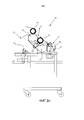
фигура 1 изображает вид сбоку устройства для нанесения, в соответствии с изобретением, в нерабочем состоянии и частично разобранного;figure 1 depicts a side view of a device for applying, in accordance with the invention, inoperative and partially disassembled;
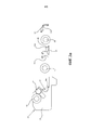
фигура 2а изображает покомпонентный вид сбоку устройства для нанесения, в соответствии с изобретением, в конфигурации для использования с клеями низкой вязкости;figure 2A depicts an exploded side view of a device for applying, in accordance with the invention, in a configuration for use with adhesives of low viscosity;
фигура 2b изображает вид сбоку устройства для нанесения, показанного на фигуре 2а, в рабочем состоянии;figure 2b depicts a side view of the device for applying, shown in figure 2A, in working condition;
фигура 2с изображает вид сбоку устройства для нанесения, показанного на фигуре 1а, в ходе работы;Figure 2c is a side view of the application device shown in Figure 1a during operation;
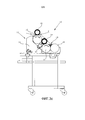
фигура 3а изображает покомпонентный вид сбоку устройства для нанесения в соответствии с изобретением в конфигурации для использования с клеями высокой вязкости;Figure 3a is an exploded side view of an application device according to the invention in a configuration for use with high viscosity adhesives;
фигура 3b изображает вид сбоку устройства для нанесения, показанного на фигуре 3а, в рабочем состоянии;figure 3b depicts a side view of the device for applying, shown in figure 3A, in working condition;
фигура 3с изображает вид сбоку устройства для нанесения, показанного на фигуре 3а, в ходе работы.Figure 3c is a side view of the application device shown in Figure 3a during operation.
Со ссылкой на прилагаемые чертежи устройство для нанесения, обозначенное ссылочной позицией 10, содержит пару обращенных друг к другу упоров 11 (на виде сбоку видно лишь один упор), предназначенных для поддержания концов распределительных роликов, установленных между ними.With reference to the accompanying drawings, the application device, indicated by the
Более точно на указанных упорах установлен по меньшей мере один первый заборный ролик 12 в контакте с клеем в зоне забора 13 (фигуры 2b, 3c), предназначенный для забора определенного количества указанного клея для его перевода на смежный ролик.More precisely, at least one
Еще более точно указанный ролик снабжен опорным валом с двумя выступающими боковыми концами (не показано на чертеже), помещенными соответственно в гнезда на каждом из двух упоров, предпочтительно, фиксированным образом.Even more precisely, said roller is provided with a support shaft with two protruding lateral ends (not shown in the drawing), respectively placed in sockets on each of the two stops, preferably in a fixed manner.
На указанных упорах 11 также закреплен по меньшей мере один второй ролик 14, который вращается в контакте с первым роликом 12, предназначенный для приема определенного количества клея, забранного из зоны 13 забора, с первого ролика 12, и третий ролик 15, который вращается в контакте со вторым роликом 14.At least one
Третий ролик 15 установлен подобно первому ролику 12, в то время как второй ролик 14 может, предпочтительно, быть установлен на опоре 16 (фигуры 2с, 3с), которая будет позволять ему совершать небольшие перемещения относительно первого и третьего роликов 12, 15.The
Особенностью изобретения является то, что указанные упоры 11 содержат по меньшей мере один неподвижный участок 19 и один подвижный участок 20, 21, который может быть прочно присоединен к неподвижному участку, например, с помощью винтов или других подобных соединительных приспособлений.A feature of the invention is that said
В соответствии с изобретением указанный подвижный участок 20, 21 может иметь такую конфигурацию, чтобы принимать резервуар 17, в котором находится указанная зона 13 забора клея (фиг. 2а-2с) или альтернативно для размещения четвертого ролика 18. Более точно указанный четвертый ролик 18 помещен по существу в контакт с первым роликом 12 так, чтобы зона 13 забора располагалась в верхнем пространстве между двумя указанными роликами (фиг. 3а-3с).In accordance with the invention, said
Данная особенность позволяет устройству для нанесения трансформироваться из конфигурации для использования с клеями низкой вязкости, такими как клеи на основе растворителя или клеи на водной основе (фиг. 2b), в конфигурацию для использования с клеями высокой вязкости, такими как клеи, не содержащие растворителя (фиг. 3b), и наоборот.This feature allows the application device to transform from a configuration for use with low viscosity adhesives, such as solvent based adhesives or water based adhesives (FIG. 2b), to a configuration for use with high viscosity adhesives such as solvent free adhesives ( Fig. 3b), and vice versa.
Более точно в одном варианте подвижный участок 20 может иметь такую конфигурацию, чтобы размещать резервуар 17, размещенный около первого ролика 12, так, чтобы по меньшей мере одна часть его поверхности могла входить в контакт с зоной 13 забора клея, содержащейся внутри него.More precisely, in one embodiment, the
Предпочтительно указанный резервуар 17 может содержать ракельную камеру 22, прочно присоединенную к подвижному участку 20 каждого упора с помощью двух опорных скоб.Preferably, said
В данной конфигурации первый ролик 12 может представлять собой ролик анилоксового типа, что означает, что он имеет поверхность, на которой выполнена гравировка, с тем, чтобы сформировать микроскопические ячейки, в которых может быть расположено некоторое количество клея. Предпочтительно поверхность указанного первого ролика 12 выполнена из керамического материала. Ракельная камера, предпочтительно, таким образом сформирована парой ракелей, которые когда они приведены в контакт с подвижной поверхностью первого ролика 12, удаляют излишки клея и оставляют лишь то количество, которое содержится в микроскопических ячейках.In this configuration, the
Клей, содержащийся в микроскопических ячейках первого ролика 12, затем переводится в тонкий слой на втором ролике 14, который вращается в контакте с первым.The glue contained in the microscopic cells of the
В соответствии с предпочтительным вариантом указанный второй ролик 14 покрыт слоем резины, и предпочтительно, слоем вулканизированной резины.In a preferred embodiment, said
Устройство для нанесения такой конфигурации, таким образом, подходит для работы с клеями низкой вязкости, такими как клеи на основе растворителя или клеи на водной основе.A device for applying such a configuration is thus suitable for working with low viscosity adhesives such as solvent based adhesives or water based adhesives.
Работа устройства для нанесения, при таких условиях работы, включает пленку F, частично намотанную на третий ролик 15 и проходящую между ним и вторым роликом 14, от которого она забирает клей в форме тонкого слоя (фиг. 2с).The operation of the application device under these operating conditions includes a film F partially wound on the
Как сказано выше, указанный подвижный участок 21 может альтернативно иметь такую конфигурацию, чтобы размещать четвертый ролик 18, размещенный вблизи и практически в контакте с первым роликом 12.As stated above, said
Указанный четвертый ролик 18 не вращается, а остается закрепленным на своей оси. Более точно на указанном подвижном участке есть гнездо 25 для размещения опорного вала указанного четвертого ролика 18 так же, как предусмотрено для первого и третьего роликов 12, 15.The specified
Еще более точно указанный подвижный участок 21 в данной конфигурации, имеет такую форму, чтобы поддерживать указанные ролики 12, 18 на расстоянии (с зазором) всего в несколько сотых миллиметра друг от друга.Even more accurately, said
Клей подается в зону 13 забора, которая в данном случае расположена в верхней части двух роликов 12, 18, так что после вращения первого ролика 12 тонкий слой клея остается на нем, нанесенный через зазор в несколько сотых миллиметра.The glue is fed into the
В такой конфигурации указанный первый ролик 12 может иметь полностью гладкую поверхность, предпочтительно, изготовленную из хромированной стали.In such a configuration, said
Указанный слой клея затем переводится от первого ролика 12 на второй ролик 14 и затем на третий ролик 15, при этом каждый ролик вращается быстрее, чем предыдущий ролик, что делает слой клея еще тоньше.The specified adhesive layer is then transferred from the
Устройство для нанесения в такой конфигурации, таким образом, подходит для работы с клеями высокой вязкости, такими как клеи, не содержащие растворителя.The application device in this configuration is thus suitable for working with high viscosity adhesives, such as solvent-free adhesives.
В соответствии с изобретением на указанном подвижном участке 20, 21 упора 11 выполнена по меньшей мере часть гнезда 26 для размещения опорного вала (не показано на чертеже) указанного первого заборного ролика 12.In accordance with the invention, at least a portion of a
На практике часть 26b указанного гнезда выполнена на указанном подвижном участке 20, 21 упора 11, и оставшаяся часть 26а выполнена на неподвижном участке 19.In practice, a
Когда подвижный участок 20, 21 соединен с неподвижным участком 19, гнездо 26 может размещать и удерживать вал первого ролика 12.When the
Таким образом, путем удаления и замены подвижного участка 20, 21 каждого упора можно как заменить резервуар 17 четвертым роликом 18 (или наоборот), так и заменить первый ролик 13 другим роликом, имеющим полностью гладкую поверхность, или роликом анилоксового типа с выгравированной поверхностью.Thus, by removing and replacing the
При помощи нескольких простых операций, таким образом, устройство для нанесения может быть трансформировано для использования с клеями низкой вязкости, такими как клеи на основе растворителя, или с клеями высокой вязкости, такими как клеи, не содержащие растворителя.With a few simple steps, the application device can thus be transformed for use with low viscosity adhesives, such as solvent based adhesives, or with high viscosity adhesives, such as solvent free adhesives.
Предпочтительно указанный подвижный участок 21, когда он имеет конфигурацию для приема четвертого ролика 18, может иметь такую форму, чтобы поддерживать первый ролик 12 и указанный четвертый ролик 18 так, чтобы их оси были выровнены по существу в горизонтальной плоскости. Это позволяет использовать верхнюю часть между роликами для приема зоны 13 забора клея.Preferably, said
В соответствии с предпочтительным вариантом указанный подвижный участок 21 может содержать дополнительный подвижный участок 28, который может быть прочно присоединен к нему, в котором выполнена часть 25b гнезда 25 для размещения вала указанного четвертого ролика 18.According to a preferred embodiment, said
Оставшаяся часть 25а гнезда 25, с другой стороны, расположена на подвижном участке 21.The remaining part 25a of the
Такая конфигурация обеспечивает еще более простую установку и снятие четвертого ролика 18 на упоры 11 устройства для нанесения.This configuration provides an even simpler installation and removal of the
В соответствии с другим вариантом устройство для нанесения может также содержать пятый прижимной ролик 27, который вращается в контакте с третьим роликом 15.According to another embodiment, the application device may also comprise a
Когда устройство для нанесения принимает конфигурацию для работы с клеями низкой вязкости, пленка F частично наматывается вокруг третьего ролика 15 на угол, определенный точками контакта указанного третьего ролика 15 со вторым роликом 14 и с указанным пятым прижимным роликом 27 соответственно.When the application device adopts a configuration for working with low viscosity adhesives, the film F is partially wound around the
Наоборот, когда устройство для нанесения принимает конфигурацию для работы с клеями высокой вязкости, пленка F частично наматывается на указанный пятый прижимной ролик 27 под изменяемым углом так, что она входит в контакт с третьим роликом в точке забора клея.On the contrary, when the application device adopts a configuration for working with high viscosity adhesives, the film F is partially wound onto said
Также в соответствии с другим предпочтительным вариантом первый ролик 12 для забора и/или третий ролик 15, и/или четвертый ролик 18 могут быть оборудованы подогревающими приспособлениями для нагрева поверхности при необходимости.Also in accordance with another preferred embodiment, the first pick-up
Предпочтительно указанные приспособления могут содержать проходы на внутренней стороне ролика и под поверхностью, по которым может циркулировать теплопроводящая среда (вода или эквивалентные растворы), нагретые специальным нагревающими устройствами.Preferably, said devices can comprise passages on the inside of the roller and below the surface through which a heat-conducting medium (water or equivalent solutions) can be circulated, heated by special heating devices.
Это особенно полезно, когда устройство для нанесения используется с клеями, не содержащими растворителя, или другими клеями высокой вязкости, которые требуется поддерживать при температурах выше комнатной температуры для поддержания их вязкости, при которой они могут быть распределены.This is especially useful when the application device is used with solvent-free adhesives or other high viscosity adhesives that need to be maintained at temperatures above room temperature to maintain their viscosity at which they can be distributed.
Подобным образом, при необходимости, ролики могут быть быстро охлаждены с помощью циркуляции жидкости низкой температуры внутри них.Similarly, if necessary, the rollers can be quickly cooled by circulating a low temperature liquid inside them.
Благодаря настоящему изобретению можно изготовить устройство для нанесения клея на движущуюся пленку, которое способно работать с разными типами клеев, в частности с клеями, имеющими существенно разные вязкости, такими как клеи на основе растворителя и клеи не содержащие растворителя, например.Thanks to the present invention, it is possible to manufacture a device for applying adhesive to a moving film that is capable of working with different types of adhesives, in particular adhesives having substantially different viscosities, such as solvent-based adhesives and solvent-free adhesives, for example.
Более точно устройство для нанесения в такой конфигурации может быть подготовлено для использования с заданным типом клея всего за несколько минут путем применения подвижных участков 20, 21, предназначенных для размещения ракельной камеры 22 или для размещения четвертого ролика 18.More precisely, the application device in this configuration can be prepared for use with a given type of glue in just a few minutes by using
Подобным образом легко может быть установлен первый ролик 12, оборудованный гравированной поверхностью, для использования с ракельной камерой 22, или ролик с гладкой поверхностью для использования во взаимодействии с четвертым роликом 18.Similarly, a
Устройство для нанесения в соответствии с настоящим изобретением также не имеет сложной конструкции, как у известных устройств, и при этом способно обеспечить такую же надежность и затраты на производство.The application device in accordance with the present invention also does not have a complex structure, as with the known devices, and is capable of providing the same reliability and production costs.
Настоящее изобретение, как описано и проиллюстрировано, может претерпевать различные модификации и варианты, все из которых лежат в пределах изобретения; более того, все детали могут быть заменены другими технически эквивалентными элементами.The present invention, as described and illustrated, may undergo various modifications and variations, all of which are within the scope of the invention; furthermore, all parts can be replaced by other technically equivalent elements.
Claims (15)
Applications Claiming Priority (3)
| Application Number | Priority Date | Filing Date | Title |
|---|---|---|---|
| IT000011A ITPC20130011A1 (en) | 2013-03-27 | 2013-03-27 | GROUP FOR THE COATING OF AN ADHESIVE ON A MOVING MOVIE |
| ITPC2013A000011 | 2013-03-27 | ||
| PCT/IB2014/060002 WO2014155251A1 (en) | 2013-03-27 | 2014-03-20 | Unit for spreading an adhesive onto a moving film |
Publications (2)
| Publication Number | Publication Date |
|---|---|
| RU2015145817A RU2015145817A (en) | 2017-05-04 |
| RU2650958C2 true RU2650958C2 (en) | 2018-04-18 |
Family
ID=48485322
Family Applications (1)
| Application Number | Title | Priority Date | Filing Date |
|---|---|---|---|
| RU2015145817A RU2650958C2 (en) | 2013-03-27 | 2014-03-20 | Unit for spreading adhesive onto moving film |
Country Status (13)
| Country | Link |
|---|---|
| US (1) | US9675988B2 (en) |
| EP (1) | EP2978603B1 (en) |
| CN (1) | CN105142905B (en) |
| AU (1) | AU2014242567B2 (en) |
| BR (1) | BR112015020676B1 (en) |
| CA (1) | CA2907669C (en) |
| ES (1) | ES2748630T3 (en) |
| IT (1) | ITPC20130011A1 (en) |
| PL (1) | PL2978603T3 (en) |
| PT (1) | PT2978603T (en) |
| RU (1) | RU2650958C2 (en) |
| WO (1) | WO2014155251A1 (en) |
| ZA (1) | ZA201506822B (en) |
Families Citing this family (1)
| Publication number | Priority date | Publication date | Assignee | Title |
|---|---|---|---|---|
| ITUA20164002A1 (en) * | 2016-05-31 | 2017-12-01 | Remac Converting S R L | METHOD AND DEVICE FOR CLEANING ROLLERS OF A COATING GROUP |
Citations (4)
| Publication number | Priority date | Publication date | Assignee | Title |
|---|---|---|---|---|
| US2912960A (en) * | 1956-08-29 | 1959-11-17 | Robert S Black | Roll type glue spreaders, surface coaters, and the like |
| EP0324892A2 (en) * | 1987-10-30 | 1989-07-26 | NORDMECCANICA S.p.A. | Plastic film bonding machine with adhesive spreading devices |
| WO2002036343A1 (en) * | 2000-10-31 | 2002-05-10 | Adlamco, Inc. | Process for coating and laminating film using 100% solids adhesive at room temperature |
| US20060219165A1 (en) * | 2005-04-04 | 2006-10-05 | Nordmeccanica S.P.A. | Adhesive-spreading unit, in particular for bonding machines |
Family Cites Families (2)
| Publication number | Priority date | Publication date | Assignee | Title |
|---|---|---|---|---|
| IT1317150B1 (en) * | 2000-03-28 | 2003-05-27 | Novachem Ind S R L | DEVICE FOR THE AUTOMATIC ADJUSTMENT OF THE QUANTITY ADHESIVE DEPOSITED, IN MACHINES FOR THE LAMINATION OF FLEXIBLE FILMS |
| DE10324729A1 (en) * | 2003-05-31 | 2004-12-16 | Bhs Corrugated Maschinen- Und Anlagenbau Gmbh | Method and gluing unit for continuous gluing of webs |
-
2013
- 2013-03-27 IT IT000011A patent/ITPC20130011A1/en unknown
-
2014
- 2014-03-20 RU RU2015145817A patent/RU2650958C2/en active
- 2014-03-20 PL PL14722336T patent/PL2978603T3/en unknown
- 2014-03-20 CN CN201480018118.5A patent/CN105142905B/en active Active
- 2014-03-20 US US14/780,063 patent/US9675988B2/en active Active
- 2014-03-20 ES ES14722336T patent/ES2748630T3/en active Active
- 2014-03-20 BR BR112015020676-0A patent/BR112015020676B1/en active IP Right Grant
- 2014-03-20 PT PT147223366T patent/PT2978603T/en unknown
- 2014-03-20 AU AU2014242567A patent/AU2014242567B2/en active Active
- 2014-03-20 EP EP14722336.6A patent/EP2978603B1/en active Active
- 2014-03-20 WO PCT/IB2014/060002 patent/WO2014155251A1/en active Application Filing
- 2014-03-20 CA CA2907669A patent/CA2907669C/en active Active
-
2015
- 2015-09-15 ZA ZA2015/06822A patent/ZA201506822B/en unknown
Patent Citations (4)
| Publication number | Priority date | Publication date | Assignee | Title |
|---|---|---|---|---|
| US2912960A (en) * | 1956-08-29 | 1959-11-17 | Robert S Black | Roll type glue spreaders, surface coaters, and the like |
| EP0324892A2 (en) * | 1987-10-30 | 1989-07-26 | NORDMECCANICA S.p.A. | Plastic film bonding machine with adhesive spreading devices |
| WO2002036343A1 (en) * | 2000-10-31 | 2002-05-10 | Adlamco, Inc. | Process for coating and laminating film using 100% solids adhesive at room temperature |
| US20060219165A1 (en) * | 2005-04-04 | 2006-10-05 | Nordmeccanica S.P.A. | Adhesive-spreading unit, in particular for bonding machines |
Non-Patent Citations (1)
| Title |
|---|
| Шварц О. и другие, Переработка пластмасс, Санкт-Петербург, Профессия, 2005, с.41-45. * |
Also Published As
| Publication number | Publication date |
|---|---|
| ZA201506822B (en) | 2019-09-25 |
| CN105142905A (en) | 2015-12-09 |
| ES2748630T3 (en) | 2020-03-17 |
| EP2978603B1 (en) | 2019-07-03 |
| US9675988B2 (en) | 2017-06-13 |
| US20160038963A1 (en) | 2016-02-11 |
| AU2014242567B2 (en) | 2017-06-29 |
| BR112015020676A2 (en) | 2017-07-18 |
| WO2014155251A1 (en) | 2014-10-02 |
| RU2015145817A (en) | 2017-05-04 |
| AU2014242567A1 (en) | 2015-10-01 |
| EP2978603A1 (en) | 2016-02-03 |
| PT2978603T (en) | 2019-10-18 |
| ITPC20130011A1 (en) | 2014-09-28 |
| CA2907669A1 (en) | 2014-10-02 |
| PL2978603T3 (en) | 2020-03-31 |
| CA2907669C (en) | 2018-05-29 |
| BR112015020676B1 (en) | 2021-05-11 |
| CN105142905B (en) | 2017-12-19 |
Similar Documents
| Publication | Publication Date | Title |
|---|---|---|
| CN107150006B (en) | Apparatus and method for applying adhesive to a substrate | |
| EP1830969B1 (en) | Method for defining a coating fluid pattern | |
| CN103046437B (en) | Rubber roller system and apparatus for coating | |
| RU2650958C2 (en) | Unit for spreading adhesive onto moving film | |
| CN104607354A (en) | Polyvinyl chloride (PVC) roller painting device and PVC roller painting technology | |
| CN216261644U (en) | Film rubber coating adjustable device | |
| CN105665221A (en) | Reverse precise sizing device | |
| GB2213406A (en) | Coating apparatus | |
| CN211937608U (en) | Gluing scraper for iron core production | |
| CN208004230U (en) | A kind of coating complex machine sizer | |
| JP2016000371A (en) | Roll coating device | |
| CN106597756B (en) | Transfer printing device | |
| CN215518157U (en) | Paper machine glue applying device capable of uniformly applying glue | |
| CN109514991A (en) | A kind of scraper clamp device and its scraping fluid method, alignment film printing machine | |
| CN110614191A (en) | Substrate silicon coating machine for adhesive sticker label | |
| CN212550238U (en) | Even rubber coating device of printing packing | |
| CN206229599U (en) | A kind of Frictioning device and resin invade automatic doubler surface glouer | |
| JP6028628B2 (en) | Electrode manufacturing equipment | |
| JP2007075724A (en) | Coating method and coater | |
| JPH0440254A (en) | Apparatus for manufacturing re-release sheet | |
| CN205219769U (en) | Lithium cell polymer dielectric film preparation knife coating is with manual device of filming | |
| JP2014226636A (en) | Print-coating device | |
| JP2022167224A (en) | roll coater | |
| RU120653U1 (en) | DEVICE FOR FORMING OIL COATING ON ROLL POLYMER MATERIAL | |
| JP2014079694A (en) | Gravure coating device |