RU2648746C1 - Device for measuring absolute integrated coefficients of the transmission of microwaves - Google Patents
Device for measuring absolute integrated coefficients of the transmission of microwaves Download PDFInfo
- Publication number
- RU2648746C1 RU2648746C1 RU2016148975A RU2016148975A RU2648746C1 RU 2648746 C1 RU2648746 C1 RU 2648746C1 RU 2016148975 A RU2016148975 A RU 2016148975A RU 2016148975 A RU2016148975 A RU 2016148975A RU 2648746 C1 RU2648746 C1 RU 2648746C1
- Authority
- RU
- Russia
- Prior art keywords
- microwave
- port
- mixer
- intermediate frequency
- switch
- Prior art date
Links
Images

Classifications
-
- G—PHYSICS
- G01—MEASURING; TESTING
- G01R—MEASURING ELECTRIC VARIABLES; MEASURING MAGNETIC VARIABLES
- G01R27/00—Arrangements for measuring resistance, reactance, impedance, or electric characteristics derived therefrom
- G01R27/28—Measuring attenuation, gain, phase shift or derived characteristics of electric four pole networks, i.e. two-port networks; Measuring transient response
Abstract
Description
Изобретение относится к радиоизмерительной технике и может быть использовано при измерении абсолютных комплексных коэффициентов передачи СВЧ-смесителей и СВЧ-устройств с преобразованием частоты.The invention relates to a radio measuring technique and can be used to measure the absolute complex transmission coefficients of microwave mixers and microwave devices with frequency conversion.
Известны устройства для измерения амплитудно-частотных и фазочастотных характеристик четырехполюсников, содержащие два генератора качающейся частоты, блок управления генераторами, исследуемый четырехполюсник с преобразованием частоты, смеситель фазовой автоподстройки частоты, блок фазовой автоподстройки частоты, два смесителя промежуточной частоты измерительного и опорного каналов, генератор промежуточных частот, фазовый детектор, двухканальный амплитудно-фазовый индикатор и вспомогательный смеситель, а также элемент сравнения и управляемый аттенюатор (а. с. №918890, МПК5 G01R 27/28 и а.с. №1075195, МПК5 G01R 27/28, опубл. 23.02.1984). Помимо параметров четырехполюсников без преобразования частоты, с помощью этих устройств возможно измерение параметров четырехполюсников с преобразованием частоты и СВЧ-смесителей. С помощью указанных устройств возможно измерять лишь относительный комплексный коэффициент передачи испытуемого СВЧ-смесителя. При этом с их помощью нельзя определить абсолютный комплексный коэффициент передачи испытуемого СВЧ-смесителя.Known devices for measuring the amplitude-frequency and phase-frequency characteristics of four-port networks, containing two oscillators of oscillating frequency, a generator control unit, a studied four-terminal network with frequency conversion, a phase locked loop, a phase locked loop, two intermediate frequency mixers of the measuring and reference channels, an intermediate frequency generator , phase detector, two-channel amplitude-phase indicator and auxiliary mixer, as well as a comparison element and controlled attenuator (a.s. No. 918890, IPC 5 G01R 27/28 and a.s. No. 1075195, IPC 5 G01R 27/28, publ. 23.02.1984). In addition to the parameters of the four-terminal network without frequency conversion, using these devices it is possible to measure the parameters of the four-terminal network with frequency conversion and microwave mixers. Using these devices, it is possible to measure only the relative complex transfer coefficient of the tested microwave mixer. Moreover, with their help it is impossible to determine the absolute complex transfer coefficient of the tested microwave mixer.
Известны устройства для измерения амплитудно-частотных и фазочастотных характеристик четырехполюсников с преобразованием частоты, состоящие из измерительного фазового моста на основе испытуемого и опорного четырехполюсников с преобразованием частоты, генератора испытательных сигналов, векторного вольтметра и переключателей (а.с. №1538149, МПК5 G01R 27/28 и а.с. №1599811, MHK5 G01R 27/28, опубл. 15.10.1990).Known devices for measuring the amplitude-frequency and phase-frequency characteristics of four-terminal with frequency conversion, consisting of a measuring phase bridge based on the test and reference four-terminal with frequency conversion, test signal generator, vector voltmeter and switches (AS No. 1538149, IPC 5 G01R 27 / 28 and A.S. No. 1599811, MHK 5 G01R 27/28, publ. 10/15/1990).
Известно устройство для определения коэффициентов передачи преобразователей частоты, состоящее из испытуемого преобразователя частоты, двух опорных преобразователей частоты и векторного анализатора цепей (патент США №6064694, МПК H04B 3/46).A device for determining the transmission coefficients of frequency converters is known, consisting of a tested frequency converter, two reference frequency converters and a vector network analyzer (US patent No. 6064694, IPC H04B 3/46).
Однако указанные устройства обладают погрешностями измерений, которые возникают за счет рассогласований СВЧ-трактов и отражений в СВЧ-соединителях при многочисленных переключениях и соединениях, необходимых для реализации различных режимов измерений.However, these devices have measurement errors that arise due to mismatches of the microwave paths and reflections in the microwave connectors with the numerous switches and connections required to implement various measurement modes.
Наиболее близким по технической сущности к предлагаемому является устройство для измерения абсолютных комплексных коэффициентов передачи и отражения СВЧ-устройств с преобразованием частоты, содержащее испытуемый СВЧ-четырехполюсник, измеритель параметров четырехполюсников СВЧ, состоящий из генератора испытательных СВЧ-сигналов, первого переключателя и связанной с ним согласованной нагрузки, СВЧ-гетеродина, первого, второго, третьего, четвертого направленных ответвителей, векторного вольтметра с выходным контактом, первого и второго портов, испытуемый СВЧ-смеситель, опорный СВЧ-смеситель, СВЧ-генератор, смеситель фазовой автоподстройки частоты, фазовый детектор, первый и второй смесители промежуточной частоты, второй, третий, четвертый переключатели, генератор опорных частот, компаратор и компьютер, образующие вместе с испытуемым СВЧ-смесителем, опорным СВЧ-смесителем и СВЧ-генератором двухканальный супергетеродинный приемник. Описанные элементы в совокупности образуют устройство, позволяющее измерять абсолютные комплексные коэффициенты передачи и отражения испытуемого СВЧ-смесителя без выполнения переключений и переподсоединений в СВЧ-трактах. (патент РФ №2524049, МПК G01R 27/28 (2006.01), опубл. 27.07.2014).The closest in technical essence to the proposed one is a device for measuring the absolute complex transmission and reflection coefficients of microwave devices with frequency conversion, containing the tested microwave four-terminal device, a microwave four-terminal parameter meter, consisting of a generator of test microwave signals, the first switch and associated matched load, microwave oscillator, first, second, third, fourth directional couplers, vector voltmeter with output contact, first and second port, test microwave mixer, microwave reference mixer, microwave generator, phase locked loop, phase detector, first and second intermediate frequency mixers, second, third, fourth switches, reference frequency generator, comparator and computer the tested microwave mixer, reference microwave mixer and microwave generator two-channel superheterodyne receiver. The described elements together form a device that allows you to measure the absolute complex transmission and reflection coefficients of the tested microwave mixer without performing switching and reconnecting in the microwave paths. (RF patent No. 2524049, IPC G01R 27/28 (2006.01), publ. 07.27.2014).
Однако такое устройство обладает амплитудно-фазовой погрешностью, которая возникает при измерении измерителем параметров четырехполюсников СВЧ суммарного комплексного коэффициента передачи испытуемого и опорного СВЧ-смесителей, соединенных последовательно, поскольку в таком режиме измерений устройство не учитывает ослабление сигнала промежуточной частоты, обусловленное потерями преобразования в испытуемом СВЧ-смесителе, а также не позволяет использовать измеритель параметров четырехполюсников СВЧ, не имеющий отдельного вывода зондирующего сигнала.However, such a device has an amplitude-phase error that occurs when the meter measures the parameters of the microwave four-terminal devices of the total complex transfer coefficient of the test and reference microwave mixers connected in series, since in this measurement mode the device does not take into account the attenuation of the intermediate frequency signal due to conversion losses in the tested microwave -mixer, and also does not allow the use of a microwave four-terminal parameter meter that does not have a separate output sounding signal.
Техническим результатом заявляемого изобретения является увеличение точности измерения абсолютного комплексного коэффициента передачи и повышение универсальности устройства.The technical result of the claimed invention is to increase the accuracy of measuring the absolute complex transfer coefficient and increase the versatility of the device.
В устройстве для измерения абсолютных комплексных коэффициентов передачи и отражения СВЧ-устройств с преобразованием частоты, которое взято за прототип, компаратор будем называть измерителем разности фаз и отношения уровней, а измеритель параметров четырехполюсников СВЧ-векторным анализатором цепей.In a device for measuring the absolute complex transmission and reflection coefficients of microwave devices with frequency conversion, which is taken as a prototype, we will call the comparator a phase difference and level ratio meter, and a four-terminal parameter meter a microwave vector network analyzer.
Для достижения технического результата предлагается устройство для измерения абсолютных комплексных коэффициентов передачи СВЧ-смесителей, содержащее векторный анализатор цепей, испытуемый СВЧ-смеситель, опорный СВЧ-смеситель, СВЧ-гетеродин, смеситель промежуточной частоты, первый переключатель, второй переключатель, третий переключатель, измеритель разности фаз и отношения уровней, первый и второй направленные ответвители и дополнительно введенные усилитель промежуточной частоты, регулируемый аттенюатор, делитель мощности. При этом первый порт векторного анализатора цепей соединен с первым портом второго направленного ответвителя, третий порт которого соединен с третьим портом делителя мощности, второй порт которого соединен с третьим портом первого направленного ответвителя, первый порт которого соединен со вторым портом векторного анализатора цепей. Вторые порты первого и второго направленных ответвителей соединены с первыми портами опорного и испытуемого СВЧ-смесителей соответственно. Второй порт испытуемого СВЧ-смесителя соединен с СВЧ-гетеродином, вторым портом опорного СВЧ-смесителя и вторым портом смесителя промежуточной частоты, первый порт которого соединен с первым портом делителя мощности, третий порт испытуемого СВЧ-смесителя соединен со вторым неподвижным контактом второго переключателя, первый неподвижный контакт которого соединен со вторым неподвижным контактом первого переключателя, подвижный контакт которого соединен с третьим портом опорного смесителя, а первый неподвижный контакт соединен с первым неподвижным контактом третьего переключателя. Подвижный контакт второго переключателя соединен с входом усилителя промежуточной частоты, выход которого соединен с входом регулируемого аттенюатора, выход которого соединен с подвижным контактом третьего переключателя, второй неподвижный контакт которого соединен со вторым входом измерителя разности фаз и отношения уровней, первый вход которого соединен с третьим портом смесителя промежуточной частоты.To achieve a technical result, a device for measuring the absolute complex transfer coefficients of microwave mixers is proposed, comprising a vector circuit analyzer, a tested microwave mixer, a microwave reference mixer, a microwave local oscillator, an intermediate frequency mixer, a first switch, a second switch, a third switch, a difference meter phases and level ratios, first and second directional couplers and additionally introduced intermediate frequency amplifier, adjustable attenuator, power divider. In this case, the first port of the vector network analyzer is connected to the first port of the second directional coupler, the third port of which is connected to the third port of the power divider, the second port of which is connected to the third port of the first directional coupler, the first port of which is connected to the second port of the vector network analyzer. The second ports of the first and second directional couplers are connected to the first ports of the reference and test microwave mixers, respectively. The second port of the tested microwave mixer is connected to the microwave local oscillator, the second port of the reference microwave mixer and the second port of the intermediate frequency mixer, the first port of which is connected to the first port of the power divider, the third port of the tested microwave mixer is connected to the second fixed contact of the second switch, the first the fixed contact of which is connected to the second fixed contact of the first switch, the movable contact of which is connected to the third port of the reference mixer, and the first fixed contact is connected to the first m fixed contact of the third switch. The movable contact of the second switch is connected to the input of the intermediate frequency amplifier, the output of which is connected to the input of the adjustable attenuator, the output of which is connected to the movable contact of the third switch, the second fixed contact of which is connected to the second input of the phase difference and level ratio meter, the first input of which is connected to the third port intermediate frequency mixer.
Общими признаками для заявляемого устройства и прототипа являются: векторный анализатор цепей, который в прототипе называется измерителем параметров четырехполюсников СВЧ, испытуемый СВЧ-смеситель, опорный СВЧ-смеситель, СВЧ-гетеродин, смеситель промежуточной частоты, первый переключатель, второй переключатель, третий переключатель, первый и второй направленные ответвители, и измеритель разности фаз и отношения уровней, который в прототипе называется компаратором.Common features for the claimed device and prototype are: a vector circuit analyzer, which in the prototype is called a microwave four-terminal parameter meter, a tested microwave mixer, a microwave reference mixer, a microwave local oscillator, an intermediate frequency mixer, the first switch, the second switch, the third switch, the first and the second directional couplers, and a phase difference meter and level ratio, which in the prototype is called a comparator.
Отличительными признаками предлагаемого устройства для измерения абсолютных комплексных коэффициентов передачи СВЧ-смесителей являются введенные в него усилитель промежуточной частоты, регулируемый аттенюатор и делитель мощности. Связи вновь введенных элементов между собой и общими с прототипом элементами в совокупности образуют устройство, позволяющее устранить амплитудно-фазовую погрешность при определении абсолютных комплексных коэффициентов передачи испытуемого СВЧ-смесителя и использовать измеритель параметров четырехполюсников СВЧ, не имеющий отдельного вывода зондирующего сигнала. За счет этого увеличивается точность измерений и повышается универсальность устройства.Distinctive features of the proposed device for measuring the absolute complex transfer factors of microwave mixers are the intermediate frequency amplifier, an adjustable attenuator and a power divider introduced into it. The connections of the newly introduced elements with each other and with the elements common with the prototype together form a device that allows to eliminate the amplitude-phase error in determining the absolute complex transfer coefficients of the tested microwave mixer and use a four-terminal microwave parameter meter that does not have a separate probe signal output. Due to this, the accuracy of measurements increases and the versatility of the device.
На чертеже представлена блок-схема предлагаемого устройства для определения абсолютных комплексных коэффициентов передачи СВЧ-смесителей.The drawing shows a block diagram of the proposed device for determining the absolute complex transfer coefficients of microwave mixers.
Устройство для измерения абсолютных комплексных коэффициентов передачи СВЧ-смесителей содержит векторный анализатор цепей (ВАЦ) 1, первый направленный ответвитель 2, делитель мощности 3, второй направленный ответвитель 4, СВЧ-гетеродин 5, опорный СВЧ-смеситель 6, испытуемый СВЧ-смеситель 7, смеситель промежуточной частоты 8, первый переключатель 9, второй переключатель 10, усилитель промежуточной частоты 11, регулируемый аттенюатор 12, третий переключатель 13, измеритель разности фаз и отношения уровней 14.A device for measuring the absolute complex transfer coefficients of microwave mixers contains a vector network analyzer (VAC) 1, a first
Первый порт ВАЦ 1 соединен с первым портом второго направленного ответвителя 4, третий порт которого соединен с третьим портом делителя мощности 3, второй порт которого соединен с третьим портом первого направленного ответвителя 2, первый порт которого соединен со вторым портом векторного анализатора цепей 1. Второй порт второго направленного ответвителя 4 соединен с первым портом испытуемого СВЧ-смесителя 7, второй порт которого соединен с СВЧ-гетеродином 5, вторым портом опорного СВЧ-смесителя 6 и вторым портом смесителя промежуточной частоты 8, первый порт которого соединен с первым портом делителя мощности 3. Третий порт испытуемого СВЧ-смесителя 7 соединен со вторым неподвижным контактом второго переключателя 10, первый неподвижный контакт которого соединен со вторым неподвижным контактом первого переключателя 9, подвижный контакт которого соединен с третьим портом опорного смесителя 6, а первый неподвижный контакт соединен с первым неподвижным контактом третьего переключателя 13. Подвижный контакт второго переключателя 10 соединен с входом усилителя промежуточной частоты 11, выход которого соединен с входом регулируемого аттенюатора 12, выход которого соединен с подвижным контактом третьего переключателя 13. Второй неподвижный контакт третьего переключателя 13 соединен со вторым входом измерителя разности фаз и отношения уровней 14, первый вход которого соединен с третьим портом смесителя промежуточной частоты 8.The first port of
Рассмотрим работу предлагаемого устройства для определения абсолютных комплексных коэффициентов передачи СВЧ-смесителей на примере определения фазы абсолютного комплексного коэффициента передачи испытуемого СВЧ-смесителя 7, при этом модуль абсолютного комплексного коэффициента передачи будет определяют аналогично, заменив соответствующие математические операции сложения и вычитания на умножение и деление, либо оставив из их без изменения, в случае использования логарифмического масштаба единиц.Consider the operation of the proposed device for determining the absolute complex transfer coefficients of microwave mixers by determining the phase of the absolute complex transfer coefficient of the tested
Сначала первый 9 и третий 13 переключатели переводят в первое положение, а второй переключатель 10 переводят во второе положение. Это позволяет с помощью ВАЦ 1 измерить суммарный сдвиг фаз Σϕ между его первым и вторым 1 и 2 портами ВАЦ, образованный сдвигами фаз испытуемого СВЧ-смесителя 7 ϕ7, усилителя промежуточной частоты 11 ϕ11, регулируемого аттенюатора 12 ϕ12 и опорного СВЧ-смесителя 6 ϕ6 в виде: Σϕ=ϕ7+ϕ11+ϕ12+ϕ6. Первый 2 и второй 4 направленные ответвители, а также переключатели 9, 10, 13 являются линейными, пассивными и взаимными устройствами они не обладают амплитудно-фазовой погрешностью, поэтому в выражение для Σϕ их сдвиги фаз не входят. Перед началом измерений эти сдвиги фаз компенсируют либо путем выравнивания электрических длин трактов, либо при помощи математической коррекции.First, the first 9 and third 13 switches are moved to the first position, and the
Зондирующий СВЧ-сигнал с частотой ƒ1 через первый порт ВАЦ 1 и второй направленный ответвитель 4 подают на первый порт испытуемого СВЧ-смесителя 7. Этот зондирующий сигнал с частотой ƒ1 в испытуемом СВЧ-смесителе 7, с помощью сигнала с частотой ƒ2, поступающего от СВЧ-гетеродина 5 на второй порт этого смесителя, преобразуется в низкочастотный сигнал промежуточной частоты ƒ3=ƒ1-ƒ2. Сигнал промежуточной частоты ƒ3 с третьего порта испытуемого СВЧ-смесителя 7 проходит через второй переключатель 10 и усиливается с помощью усилителя промежуточной частоты 11, после чего регулируется по уровню регулируемым аттенюатором 12, а затем через третий 13 и первый 9 переключатели подается на третий порт опорного СВЧ-смесителя 6. Этот сигнал промежуточной частоты ƒ3 в опорном СВЧ-смесителе 6, с помощью сигнала с частотой ƒ2, поступающего от СВЧ-гетеродина 5 на второй порт этого смесителя, преобразуется обратно в зондирующий СВЧ-сигнал с частотой ƒ1, который поступает через первый направленный ответвитель 2 во второй порт ВАЦ 1. Благодаря обратному преобразованию частоты сигнала ƒ3 в опорном СВЧ-смесителе 6 в частоту исходного сигнала ƒ1, два последовательно соединенных между собой СВЧ-смесителя 6 и 7 воспринимаются ВАЦ 1 как обычный четырехполюсник без преобразования частоты. В результате ВАЦ 1 сравнивает по фазе сигналы на своих первом и втором портах и таким образом измеряет суммарный угол сдвига фаз Σϕ.A sounding microwave signal with a frequency of ƒ 1 through the
Затем первый 9 и третий 13 переключатели переводят во второе положение, а второй переключатель 10 в первое положение. Зондирующий СВЧ-сигнал с частотой ƒ1 через второй порт ВАЦ 1 подают на первый порт опорного СВЧ-смесителя 6. Этот зондирующий сигнал с частотой ƒ1 в опорном СВЧ-смесителе 6, с помощью сигнала с частотой ƒ2, поступающего от СВЧ-гетеродина 5 на второй порт этого смесителя, преобразуют в низкочастотный сигнал промежуточной частоты ƒ3=ƒ1-ƒ2. Сигнал промежуточной частоты ƒ3 с третьего порта опорного СВЧ-смесителя 6 через первый 9 и второй 10 переключатели поступает на усилитель промежуточной частоты 11, после чего регулируется по уровню регулируемым аттенюатором 12 и через третий переключатель 13 поступает на второй порт измерителя разности фаз и отношения уровней 14.Then, the first 9 and third 13 switches are moved to the second position, and the
На первый порт измерителя разности фаз и отношения уровней 14 поступает сигнал промежуточной частоты ƒ3=ƒ1-ƒ2 от смесителя промежуточной частоты 8, в котором он образуется путем смешивания сигнала с частотой ƒ2, поступающего от СВЧ-гетеродина 5 на второй порт этого смесителя, и сигнала с частотой ƒ1, поступающего от ВАЦ 1 через первый 2 либо второй 4 направленные ответвители, в зависимости от того, на какой из СВЧ-смесителей 6 или 7 подается зондирующий СВЧ-сигнал от ВАЦ 1: если этот сигнал подается на опорный СВЧ-смеситель 6, то используется первый направленный ответвитель 2, а если сигнал подается на испытуемый СВЧ-смеситель 7, то используется второй направленный ответвитель 4.An intermediate frequency signal ƒ 3 = ƒ 1 -ƒ 2 from an intermediate-frequency mixer 8, in which it is formed by mixing a signal with a frequency of ƒ 2 coming from the microwave local oscillator 5 to the second port of this mixer, and a signal with a frequency of ƒ 1 , coming from
Таким образом измеритель разности фаз и отношения уровней определяет следующую разность фаз: Δϕ2=ϕ6+ϕ11+ϕ12-ϕ8, где ϕ8 - сдвиг фаз, вносимый смесителем промежуточной частоты 8.Thus, the phase difference and level ratio meter determines the following phase difference: Δϕ 2 = ϕ 6 + ϕ 11 + ϕ 12 -ϕ 8 , where ϕ 8 is the phase shift introduced by the intermediate frequency mixer 8.
После этого второй переключатель 10 переводят во второе положение. Зондирующий СВЧ-сигнал с частотой ƒ1 через первый порт ВАЦ 1 и второй направленный ответвитель 4 подают на первый порт испытуемого СВЧ-смесителя 7. Этот зондирующий сигнал с частотой ƒ1 в испытуемом СВЧ-смесителе 7, с помощью сигнала с частотой ƒ2, поступающего от СВЧ-гетеродина 5 на второй порт этого смесителя, преобразуют в низкочастотный сигнал промежуточной частоты ƒ3=ƒ1-ƒ2. Сигнал промежуточной частоты ƒ3 с третьего порта испытуемого СВЧ-смесителя 7 через второй переключатель 10 поступает на усилитель промежуточной частоты 11, после чего регулируется по уровню регулируемым аттенюатором 12 и через третий переключатель 13 поступает на второй порт измерителя разности фаз и отношения уровней 14, на первый порт которого также поступает сигнал промежуточной частоты ƒ3 с третьего порта смесителя промежуточной частоты 8.After that, the
Таким образом, измеритель разности фаз и отношения уровней 14 измеряет следующую разность фаз: Δϕ1=ϕ7+ϕ11+ϕ12-ϕ8.Thus, the phase difference meter and the
В итоге определяют искомую фазу ϕ7 абсолютного комплексного коэффициента передачи испытуемого СВЧ-смесителя 7, решив следующую систему уравнений:As a result, determine the desired phase φ 7 integrated absolute transmission rate of the

в виде: 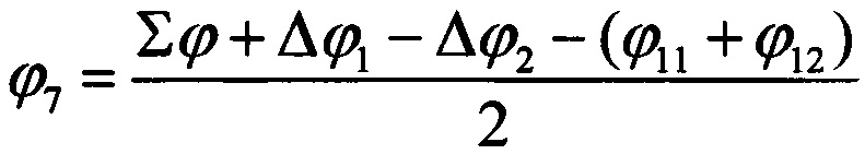
Модуль абсолютного комплексного коэффициента передачи испытуемого СВЧ-смесителя 7 определяют аналогично, заменив соответствующие математические операции сложения и вычитания на умножение и деление, либо оставив их без изменения, в случае использования логарифмического масштаба единиц.The absolute complex transfer coefficient modulus of the tested
Таким образом определяют абсолютный комплексный коэффициент передачи испытуемого СВЧ-смесителя 7.Thus, the absolute complex transfer coefficient of the tested
Наличие в заявляемом устройстве усилителя промежуточной частоты 11 и регулируемого аттенюатора 12 позволяет снизить амплитудно-фазовую погрешность измерения абсолютного комплексного коэффициента передачи испытуемого СВЧ-смесителя 7 за счет восстановления уровня сигнала промежуточной частоты до уровня зондирующего СВЧ-сигнала. Наличие в устройстве делителя мощности 3 в совокупности с первым и вторым направленными ответвителями 2 и 4 позволяет, в отличие от прототипа, применять в этом устройстве векторный анализатор цепей 1, не имеющий отдельного вывода зондирующего сигнала, за счет этого повышается универсальность устройства.The presence of an intermediate frequency amplifier 11 and an
Claims (1)
Priority Applications (1)
| Application Number | Priority Date | Filing Date | Title |
|---|---|---|---|
| RU2016148975A RU2648746C1 (en) | 2016-12-13 | 2016-12-13 | Device for measuring absolute integrated coefficients of the transmission of microwaves |
Applications Claiming Priority (1)
| Application Number | Priority Date | Filing Date | Title |
|---|---|---|---|
| RU2016148975A RU2648746C1 (en) | 2016-12-13 | 2016-12-13 | Device for measuring absolute integrated coefficients of the transmission of microwaves |
Publications (1)
| Publication Number | Publication Date |
|---|---|
| RU2648746C1 true RU2648746C1 (en) | 2018-03-28 |
Family
ID=61866996
Family Applications (1)
| Application Number | Title | Priority Date | Filing Date |
|---|---|---|---|
| RU2016148975A RU2648746C1 (en) | 2016-12-13 | 2016-12-13 | Device for measuring absolute integrated coefficients of the transmission of microwaves |
Country Status (1)
| Country | Link |
|---|---|
| RU (1) | RU2648746C1 (en) |
Citations (6)
| Publication number | Priority date | Publication date | Assignee | Title |
|---|---|---|---|---|
| SU1599811A1 (en) * | 1988-12-05 | 1990-10-15 | Предприятие П/Я А-1490 | Apparatus for measuring amplitude-frequency and phase-frequency characteristics of four-terminal networks with frequency conversion |
| RU2029966C1 (en) * | 1991-06-26 | 1995-02-27 | Минский радиотехнический институт | Method for determining frequency changer gain factor |
| DE102006035827A1 (en) * | 2006-03-15 | 2007-09-20 | Rohde & Schwarz Gmbh & Co. Kg | Frequency conversion circuit e.g. mixer, scattering parameters measuring method, involves phase coherently measuring waves converging and returning at/from gates of frequency conversion circuit even in case of different frequencies |
| US7415373B2 (en) * | 2004-07-05 | 2008-08-19 | Agilent Technologies, Inc. | Method of measuring frequency translation device |
| RU2377583C1 (en) * | 2008-09-10 | 2009-12-27 | Открытое акционерное общество "Научно-производственная компания "Ритм" | Device for measuring complex coefficients of transmission and reflection of microwave four terminal networks |
| RU2524049C1 (en) * | 2013-02-14 | 2014-07-27 | Федеральное государственное бюджетное образовательное учреждение высшего профессионального образования "Кубанский государственный университет" (ФГБОУ ВПО "КубГУ") | Device for measuring absolute complex transmission and reflection coefficients of microwave devices with frequency conversion |
-
2016
- 2016-12-13 RU RU2016148975A patent/RU2648746C1/en active
Patent Citations (6)
| Publication number | Priority date | Publication date | Assignee | Title |
|---|---|---|---|---|
| SU1599811A1 (en) * | 1988-12-05 | 1990-10-15 | Предприятие П/Я А-1490 | Apparatus for measuring amplitude-frequency and phase-frequency characteristics of four-terminal networks with frequency conversion |
| RU2029966C1 (en) * | 1991-06-26 | 1995-02-27 | Минский радиотехнический институт | Method for determining frequency changer gain factor |
| US7415373B2 (en) * | 2004-07-05 | 2008-08-19 | Agilent Technologies, Inc. | Method of measuring frequency translation device |
| DE102006035827A1 (en) * | 2006-03-15 | 2007-09-20 | Rohde & Schwarz Gmbh & Co. Kg | Frequency conversion circuit e.g. mixer, scattering parameters measuring method, involves phase coherently measuring waves converging and returning at/from gates of frequency conversion circuit even in case of different frequencies |
| RU2377583C1 (en) * | 2008-09-10 | 2009-12-27 | Открытое акционерное общество "Научно-производственная компания "Ритм" | Device for measuring complex coefficients of transmission and reflection of microwave four terminal networks |
| RU2524049C1 (en) * | 2013-02-14 | 2014-07-27 | Федеральное государственное бюджетное образовательное учреждение высшего профессионального образования "Кубанский государственный университет" (ФГБОУ ВПО "КубГУ") | Device for measuring absolute complex transmission and reflection coefficients of microwave devices with frequency conversion |
Similar Documents
| Publication | Publication Date | Title |
|---|---|---|
| RU2524049C1 (en) | Device for measuring absolute complex transmission and reflection coefficients of microwave devices with frequency conversion | |
| US9720023B2 (en) | Vector network power meter | |
| CN106249066B (en) | Method for calibrating a cable and corresponding measuring device | |
| WO2010083152A1 (en) | High frequency analysis of a device under test | |
| RU2687850C1 (en) | Measuring device and method of determining complex transfer coefficients of microwave-mixers | |
| CN110581741B (en) | Standing wave abnormal position detection method, equipment and medium | |
| RU2377583C1 (en) | Device for measuring complex coefficients of transmission and reflection of microwave four terminal networks | |
| RU2482504C2 (en) | Method for calibration of inherent s-parameters of devices for measuring complex coefficients of transmission and reflection of microwave four-terminal devices | |
| RU2648746C1 (en) | Device for measuring absolute integrated coefficients of the transmission of microwaves | |
| RU2377591C1 (en) | Method of certification of amplitude-phase error of devices for measurement of complex coefficients of transmitting and reflecting of four-pole shf | |
| RU2621368C1 (en) | Method of determining shift angle of microwave device phase with frequency transformation | |
| RU2494408C1 (en) | Measuring device of scattering parameters of four-pole at ultra-high frequency | |
| RU2276377C1 (en) | Device for measuring amplitude-frequency and phase-frequency characteristics of four-poles with frequency transformer | |
| RU2682079C1 (en) | Device for measuring complex transmission and reflection coefficients of microwave devices with frequency conversion | |
| RU2649861C1 (en) | Device for measuring complex transmission and reflection coefficients of microwave devices with frequency conversion | |
| RU2683804C1 (en) | Microwave two-terminal element complex refining coefficient modulus and argument determining method | |
| RU2805381C1 (en) | Device for measuring complex transmission and reflection coefficients of microwave quadripoles with frequency conversion | |
| RU2774501C1 (en) | Device for measuring complex transmission and reflection coefficients of microwave quadrupoles | |
| RU2646948C1 (en) | Device for measuring complex transmission and reflection coefficients of microwave devices with frequency conversion up | |
| RU2687980C1 (en) | Device for measuring complex transfer coefficients and reflection of microwave devices with frequency conversion | |
| Nikolaenko et al. | Analysis of modern techniques for automatic measurements in microwaves | |
| US20110288800A1 (en) | Method for measuring system parameter of linear multiport and measuring method using vector network analyzer | |
| RU2673781C1 (en) | Method for calibrating two-channel superheterodyne receiver in meter of complex transmission and reflection coefficients of microwave devices with frequency conversion | |
| Korotkov et al. | The method for accurate measurements of absolute phase and group delay of frequency converters | |
| JPS62240870A (en) | Test apparatus |