RU2647212C1 - Sealed assembly for optical fiber alignment - Google Patents
Sealed assembly for optical fiber alignment Download PDFInfo
- Publication number
- RU2647212C1 RU2647212C1 RU2014144530A RU2014144530A RU2647212C1 RU 2647212 C1 RU2647212 C1 RU 2647212C1 RU 2014144530 A RU2014144530 A RU 2014144530A RU 2014144530 A RU2014144530 A RU 2014144530A RU 2647212 C1 RU2647212 C1 RU 2647212C1
- Authority
- RU
- Russia
- Prior art keywords
- optical fiber
- coupling
- cavity
- grooves
- sealed
- Prior art date
Links
Images
Classifications
-
- G—PHYSICS
- G02—OPTICS
- G02B—OPTICAL ELEMENTS, SYSTEMS OR APPARATUS
- G02B6/00—Light guides; Structural details of arrangements comprising light guides and other optical elements, e.g. couplings
- G02B6/24—Coupling light guides
- G02B6/36—Mechanical coupling means
-
- G—PHYSICS
- G02—OPTICS
- G02B—OPTICAL ELEMENTS, SYSTEMS OR APPARATUS
- G02B6/00—Light guides; Structural details of arrangements comprising light guides and other optical elements, e.g. couplings
- G02B6/24—Coupling light guides
- G02B6/36—Mechanical coupling means
- G02B6/3628—Mechanical coupling means for mounting fibres to supporting carriers
- G02B6/3632—Mechanical coupling means for mounting fibres to supporting carriers characterised by the cross-sectional shape of the mechanical coupling means
- G02B6/3636—Mechanical coupling means for mounting fibres to supporting carriers characterised by the cross-sectional shape of the mechanical coupling means the mechanical coupling means being grooves
-
- G—PHYSICS
- G02—OPTICS
- G02B—OPTICAL ELEMENTS, SYSTEMS OR APPARATUS
- G02B6/00—Light guides; Structural details of arrangements comprising light guides and other optical elements, e.g. couplings
- G02B6/24—Coupling light guides
- G02B6/36—Mechanical coupling means
- G02B6/38—Mechanical coupling means having fibre to fibre mating means
- G02B6/3807—Dismountable connectors, i.e. comprising plugs
- G02B6/3833—Details of mounting fibres in ferrules; Assembly methods; Manufacture
- G02B6/3834—Means for centering or aligning the light guide within the ferrule
- G02B6/3838—Means for centering or aligning the light guide within the ferrule using grooves for light guides
- G02B6/3839—Means for centering or aligning the light guide within the ferrule using grooves for light guides for a plurality of light guides
-
- G—PHYSICS
- G02—OPTICS
- G02B—OPTICAL ELEMENTS, SYSTEMS OR APPARATUS
- G02B6/00—Light guides; Structural details of arrangements comprising light guides and other optical elements, e.g. couplings
- G02B6/24—Coupling light guides
- G02B6/36—Mechanical coupling means
- G02B6/38—Mechanical coupling means having fibre to fibre mating means
- G02B6/3807—Dismountable connectors, i.e. comprising plugs
- G02B6/3833—Details of mounting fibres in ferrules; Assembly methods; Manufacture
- G02B6/3855—Details of mounting fibres in ferrules; Assembly methods; Manufacture characterised by the method of anchoring or fixing the fibre within the ferrule
- G02B6/3861—Adhesive bonding
-
- G—PHYSICS
- G02—OPTICS
- G02B—OPTICAL ELEMENTS, SYSTEMS OR APPARATUS
- G02B6/00—Light guides; Structural details of arrangements comprising light guides and other optical elements, e.g. couplings
- G02B6/24—Coupling light guides
- G02B6/36—Mechanical coupling means
- G02B6/38—Mechanical coupling means having fibre to fibre mating means
- G02B6/3807—Dismountable connectors, i.e. comprising plugs
- G02B6/3873—Connectors using guide surfaces for aligning ferrule ends, e.g. tubes, sleeves, V-grooves, rods, pins, balls
- G02B6/3885—Multicore or multichannel optical connectors, i.e. one single ferrule containing more than one fibre, e.g. ribbon type
-
- G—PHYSICS
- G02—OPTICS
- G02B—OPTICAL ELEMENTS, SYSTEMS OR APPARATUS
- G02B6/00—Light guides; Structural details of arrangements comprising light guides and other optical elements, e.g. couplings
- G02B6/24—Coupling light guides
- G02B6/42—Coupling light guides with opto-electronic elements
- G02B6/4201—Packages, e.g. shape, construction, internal or external details
- G02B6/4204—Packages, e.g. shape, construction, internal or external details the coupling comprising intermediate optical elements, e.g. lenses, holograms
- G02B6/4214—Packages, e.g. shape, construction, internal or external details the coupling comprising intermediate optical elements, e.g. lenses, holograms the intermediate optical element having redirecting reflective means, e.g. mirrors, prisms for deflecting the radiation from horizontal to down- or upward direction toward a device
-
- G—PHYSICS
- G02—OPTICS
- G02B—OPTICAL ELEMENTS, SYSTEMS OR APPARATUS
- G02B6/00—Light guides; Structural details of arrangements comprising light guides and other optical elements, e.g. couplings
- G02B6/24—Coupling light guides
- G02B6/42—Coupling light guides with opto-electronic elements
- G02B6/4201—Packages, e.g. shape, construction, internal or external details
- G02B6/4219—Mechanical fixtures for holding or positioning the elements relative to each other in the couplings; Alignment methods for the elements, e.g. measuring or observing methods especially used therefor
-
- G—PHYSICS
- G02—OPTICS
- G02B—OPTICAL ELEMENTS, SYSTEMS OR APPARATUS
- G02B6/00—Light guides; Structural details of arrangements comprising light guides and other optical elements, e.g. couplings
- G02B6/24—Coupling light guides
- G02B6/42—Coupling light guides with opto-electronic elements
- G02B6/4201—Packages, e.g. shape, construction, internal or external details
- G02B6/4248—Feed-through connections for the hermetical passage of fibres through a package wall
-
- G—PHYSICS
- G02—OPTICS
- G02B—OPTICAL ELEMENTS, SYSTEMS OR APPARATUS
- G02B6/00—Light guides; Structural details of arrangements comprising light guides and other optical elements, e.g. couplings
- G02B6/24—Coupling light guides
- G02B6/42—Coupling light guides with opto-electronic elements
- G02B6/4201—Packages, e.g. shape, construction, internal or external details
- G02B6/4251—Sealed packages
- G02B6/4253—Sealed packages by embedding housing components in an adhesive or a polymer material
-
- G—PHYSICS
- G02—OPTICS
- G02B—OPTICAL ELEMENTS, SYSTEMS OR APPARATUS
- G02B6/00—Light guides; Structural details of arrangements comprising light guides and other optical elements, e.g. couplings
- G02B6/24—Coupling light guides
- G02B6/42—Coupling light guides with opto-electronic elements
- G02B6/4292—Coupling light guides with opto-electronic elements the light guide being disconnectable from the opto-electronic element, e.g. mutually self aligning arrangements
-
- G—PHYSICS
- G02—OPTICS
- G02B—OPTICAL ELEMENTS, SYSTEMS OR APPARATUS
- G02B6/00—Light guides; Structural details of arrangements comprising light guides and other optical elements, e.g. couplings
- G02B6/24—Coupling light guides
- G02B6/42—Coupling light guides with opto-electronic elements
-
- Y—GENERAL TAGGING OF NEW TECHNOLOGICAL DEVELOPMENTS; GENERAL TAGGING OF CROSS-SECTIONAL TECHNOLOGIES SPANNING OVER SEVERAL SECTIONS OF THE IPC; TECHNICAL SUBJECTS COVERED BY FORMER USPC CROSS-REFERENCE ART COLLECTIONS [XRACs] AND DIGESTS
- Y10—TECHNICAL SUBJECTS COVERED BY FORMER USPC
- Y10T—TECHNICAL SUBJECTS COVERED BY FORMER US CLASSIFICATION
- Y10T29/00—Metal working
- Y10T29/49—Method of mechanical manufacture
- Y10T29/4998—Combined manufacture including applying or shaping of fluent material
Abstract
Description
Уровень техникиState of the art
1. Приоритет1. Priority
Приоритет по данной заявке принадлежит предварительной заявке на патент США №61/623,027, поданной 11 апреля 2012, и предварительной заявке на патент США №61/699,125, поданной 10 сентября 2012, которые полностью включены в данную заявку в виде ссылок. Все упомянутые далее публикации во всей своей полноте включены в данную заявку в виде ссылок.Priority for this application belongs to provisional application for US patent No. 61/623,027, filed April 11, 2012, and provisional application for US patent No. 61 / 699,125, filed September 10, 2012, which are fully incorporated into this application by reference. All of the following publications in their entirety are incorporated into this application by reference.
2. Права государства2. State rights
Данное изобретение было сделано при поддержке правительства в соответствии с контрактом №К68335-12-С-0123, заключенным с NAVAL AIR WARFARE CTR AIRCRAFT DIVISION. Правительство имеет определенные права на данное изобретение.This invention was made with the support of the government in accordance with contract No. K68335-12-C-0123 concluded with the NAVAL AIR WARFARE CTR AIRCRAFT DIVISION. The government has certain rights to this invention.
3. Область техники3. Field of technology
[0001] Данное изобретение относится к конструкциям муфты для оптического волокна, в частности герметичному узлу (сборке) для выравнивания оптического волокна, включающему муфту для выравнивания оптических волокон.[0001] The present invention relates to constructions of an optical fiber coupler, in particular an airtight assembly (alignment) for aligning an optical fiber, including a sleeve for aligning optical fibers.
4. Описание уровня техники4. Description of the prior art
[0002] Ввиду увеличивающихся требований к полосе пропускания для современной передачи данных (например, для видеоданных высокой четкости), передача сигналов по оптоволокну стала повсеместной для обмена данными. Оптические сигналы передаются по оптоволокну через оптоволоконную сеть и связанные с ней коннекторы и коммутаторы. Оптоволокно обладает значительно более высокой пропускной способностью для широкого диапазона частот и более низкими потерями сигнала по сравнению с медными проводами для заданного физического размера/протяженности.[0002] In view of the increasing bandwidth requirements for modern data transmission (for example, high-definition video), signal transmission over fiber has become ubiquitous for data exchange. Optical signals are transmitted over fiber through a fiber optic network and its associated connectors and switches. The fiber has significantly higher bandwidth for a wide frequency range and lower signal loss compared to copper wires for a given physical size / length.
[0003] При передаче сигналов по оптоволокну преобразования оптических сигналов в электрические сигналы и наоборот происходят за пределами концевого участка оптоволокна. А именно на выходном конце оптоволокна свет из оптического волокна детектируется преобразующим ресивером и конвертируется в электрический сигнал для последующей обработки данных в дальнейшем (то есть преобразование оптического сигнала в электрический). На входном конце оптического волокна электрические сигналы конвертируются в свет, который далее передается в оптоволокно преобразующим трансмиттером (то есть преобразование электрического сигнала в оптический).[0003] When transmitting signals over an optical fiber, conversions of the optical signals into electrical signals and vice versa occur outside the end portion of the optical fiber. Namely, at the output end of the optical fiber, light from the optical fiber is detected by the conversion receiver and converted into an electrical signal for subsequent data processing in the future (i.e., the conversion of the optical signal into electrical). At the input end of the optical fiber, the electrical signals are converted into light, which is then transmitted to the optical fiber by a converting transmitter (i.e., converting the electrical signal into optical).
[0004] Оптоэлектронные устройства (ресивер и трансмиттер и связанные с ними оптические элементы и электронные аппаратные средства) содержатся в оптоэлектронном модуле или блоке. Оптическое волокно вводят снаружи корпуса оптоэлектронного модуля через отверстие, предусмотренное в стенке корпуса. Конец оптического волокна оптически соединяют (стыкуют) с оптоэлектронными устройствами, находящимися внутри корпуса. Проходной элемент (переходник) поддерживает участок оптического волокна, проходящий через отверстие в стенке. Для разнообразных областей применения желательно герметично изолировать оптоэлектронные устройства внутри корпуса оптоэлектронного модуля для защиты компонентов от коррозионных сред, влажности и т.п. Так как блок оптоэлектронного модуля должен быть герметично изолирован как единое целое, проходной элемент (переходник) должен быть герметично изолирован таким образом, чтобы электрооптические компоненты внутри корпуса оптоэлектронного модуля были надежно и постоянно защищены от окружающей среды.[0004] Optoelectronic devices (receiver and transmitter and related optical elements and electronic hardware) are contained in an optoelectronic module or unit. The optical fiber is introduced outside the housing of the optoelectronic module through an opening provided in the wall of the housing. The end of the optical fiber is optically coupled (mated) with optoelectronic devices located inside the housing. A passage element (adapter) supports a portion of the optical fiber passing through an opening in the wall. For various applications, it is desirable to hermetically isolate optoelectronic devices inside the optoelectronic module housing to protect components from corrosive environments, humidity, etc. Since the block of the optoelectronic module must be hermetically insulated as a whole, the passage element (adapter) must be hermetically insulated so that the electro-optical components inside the body of the optoelectronic module are reliably and permanently protected from the environment.
[0005] До настоящего времени герметичный проходной элемент (переходник) имел форму цилиндрической втулки, задающей большой зазор, через который проходит участок оптического волокна. Оптическое волокно выходит за пределы втулки внутрь оптоэлектронного модуля. Концевой участок оптического волокна завершается в муфте (отделенной от втулки), которая выровнена (отъюстирована) относительно имеющихся в ней оптоэлектронных устройств. Изолирующий материал, такой как эпоксидная смола, применяют для герметизации зазора между оптическим волокном и внутренней стенкой втулки. Втулку вставляют в отверстие в корпусе оптоэлектронного модуля и отверстие герметизируют, как правило, припаивая наружную стенку втулки к корпусу. Внешняя стенка втулки может быть позолочена для облегчения припаивания и улучшения коррозионной устойчивости.[0005] To date, the sealed passage element (adapter) has been in the form of a cylindrical sleeve that defines a large gap through which a portion of the optical fiber passes. The optical fiber extends beyond the sleeve into the optoelectronic module. The end portion of the optical fiber terminates in the sleeve (separated from the sleeve), which is aligned (aligned) relative to the existing optoelectronic devices. An insulating material, such as epoxy resin, is used to seal the gap between the optical fiber and the inner wall of the sleeve. The sleeve is inserted into the hole in the housing of the optoelectronic module and the hole is sealed, usually by soldering the outer wall of the sleeve to the body. The outer wall of the sleeve can be gold plated to facilitate soldering and improve corrosion resistance.
[0006] Из-за того, что имеется большой зазор между втулкой и оптическим волокном, и для герметизации такого зазора используют эпоксидную смолу (то есть слой эпоксидной смолы между внешней поверхностью волокна и внутренней стенкой втулки), втулка не поддерживает оптическое волокно с каким-либо позиционным выравниванием относительно втулки. Вследствие того, что изолирующий материал обеспечивает уменьшение нагрузки и деформации для находящегося внутри него участка оптического волокна, хрупкое волокно не ломается легко во время манипуляций с ним. Втулка по существу функционирует как уплотнительное кольцо или канал, припаянный к корпусу оптоэлектронного модуля и через который проходит оптическое волокно в герметичном уплотнении внутри втулки. Как показано ниже, концевой участок оптического волокна должен быть выровнен (отъюстирован) относительно оптоэлектронных устройств в пределах приемлемых допусков с помощью муфты.[0006] Because there is a large gap between the sleeve and the optical fiber, and an epoxy resin (that is, an epoxy layer between the outer surface of the fiber and the inner wall of the sleeve) is used to seal such a gap, the sleeve does not support optical fiber with any or positional alignment relative to the sleeve. Due to the fact that the insulating material reduces the load and deformation for the portion of the optical fiber inside it, brittle fiber does not break easily during handling. The sleeve essentially functions as an o-ring or channel soldered to the housing of the optoelectronic module and through which the optical fiber passes in a sealed seal inside the sleeve. As shown below, the end portion of the optical fiber must be aligned (aligned) relative to the optoelectronic devices within acceptable tolerances using a sleeve.
[0007] Чтобы оптически соединить вход/выход оптического волокна с оптоэлектронными устройствами в оптоэлектронном модуле, оптические элементы, такие как линзы и зеркала должны коллимировать и/или фокусировать свет от источника света (например, лазера) на входной торец оптического волокна, и коллимировать и/или фокусировать свет от выходного торца оптического волокна на ресивер. Для достижения приемлемых уровней сигнала торец оптического волокна должен быть прецизионно точно выровнен с жестким допуском относительно трансмиттеров и ресиверов, так что оптоволокно прецизионно точно выравнивают по отношению к оптическим элементам, закрепленным относительно трансмиттеров и ресиверов. В прошлом такие внутренние оптические элементы и структуры, необходимые для достижения требуемой оптической юстировки (выравнивания) с приемлемым допуском, соединительные конструкции, включая соединительный порт, располагали внутри герметично изолированного корпуса оптоэлектронного модуля, к которому присоединяли муфту, замыкающую концевой участок оптического волокна. Поэтому трансмиттеры и ресиверы и связанные с ними оптические элементы и устройства подключения обычно являются громоздкими, занимающими значительное пространство, что делает их неподходящими для использования в небольших электронных устройствах. До настоящего времени оптоэлектронные модули, содержащие трансмиттеры и ресиверы, были обычно довольно дорогими и сравнительно большими по размеру для данного количества портов. Так как оптические волокна являются хрупкими, манипуляции с ними во время и после физического подключения к соединительному устройству внутри оптоэлектронного модуля следует производить с осторожностью, и необходимо избегать повреждения в проходной втулке. В случае повреждения оптического волокна необходимо было заменить весь оптоэлектронный модуль, к которому припаяна герметичная проходная втулка для оптического волокна, и это являлось отраслевой особенностью. Должен быть произведен монтаж и оптическое выравнивание (юстировка) оптических волокон относительно трансмиттеров и ресиверов, а компоненты должны производиться с субмикронной точностью, причем их производство должно быть экономичным и выполняться полностью автоматическим, высокопроизводительным способом.[0007] In order to optically connect the input / output of the optical fiber to the optoelectronic devices in the optoelectronic module, optical elements such as lenses and mirrors must collimate and / or focus light from a light source (eg, a laser) onto the input end of the optical fiber, and collimate and / or focus the light from the output end of the optical fiber to the receiver. To achieve acceptable signal levels, the end of the optical fiber must be precisely aligned with a tight tolerance with respect to transmitters and receivers, so that the optical fiber is precisely aligned with optical elements fixed to the transmitters and receivers. In the past, such internal optical elements and structures necessary to achieve the required optical alignment (alignment) with an acceptable tolerance, the connecting structures, including the connecting port, were located inside the hermetically sealed housing of the optoelectronic module, to which a sleeve was connected to close the end section of the optical fiber. Therefore, transmitters and receivers and their associated optical elements and connection devices are usually bulky, occupying significant space, which makes them unsuitable for use in small electronic devices. Until now, optoelectronic modules containing transmitters and receivers were usually quite expensive and relatively large in size for a given number of ports. Since optical fibers are brittle, they must be handled with care during and after physical connection to the connecting device inside the optoelectronic module, and damage to the bushing must be avoided. In the event of damage to the optical fiber, it was necessary to replace the entire optoelectronic module, to which a hermetic bushing for the optical fiber was soldered, and this was an industry feature. Installation and optical alignment (adjustment) of optical fibers with respect to transmitters and receivers should be carried out, and the components should be produced with submicron accuracy, and their production should be economical and carried out in a fully automatic, high-performance way.
[0008] Вышеупомянутые недостатки существующей передачи данных с использованием оптоволокна усиливаются при многоканальной оптоволоконной передаче данных.[0008] The aforementioned disadvantages of existing fiber optic data transmission are amplified by multi-channel fiber optic data transmission.
[0009] OZ Optics Ltd производит многожильный герметично изолируемый соединительный шнур со стеклянным припоем, имеющий множество оптических волокон, проходящих через втулку, с оптическими волокнами, выходящими за пределы втулки, с концевыми участками оптических волокон, фиксируемыми в выравнивающей (центрирующей) муфте отдельно от втулки. OZ Optics Ltd также производит многожильный герметично изолируемый соединительный шнур с металлическим припоем, в котором оптические волокна покрыты металлом (металлизированные волокна). Оптические волокна завершаются кремниевой муфтой, которая находится внутри втулки, являющейся компонентом, отделенным от муфты. Внешняя стенка втулки позолочена для припаивания к корпусу оптоэлектронного модуля. Однако эти многожильные герметичные проходные устройства, похоже, не преодолевают упомянутые выше недостатки существующего уровня техники и представляют дополнительную сложность и затраты, по крайней мере, с точки зрения перспектив технологичности.[0009] OZ Optics Ltd manufactures a multi-strand hermetically insulated glass-solder connection cord having a plurality of optical fibers passing through the sleeve, with optical fibers extending outside the sleeve, with end portions of the optical fibers fixed in an alignment (centering) sleeve separately from the sleeve . OZ Optics Ltd also produces a multi-core hermetically sealed connecting cord with a metal solder in which the optical fibers are coated with metal (metallized fibers). The optical fibers are terminated by a silicon sleeve, which is located inside the sleeve, which is a component separated from the sleeve. The outer wall of the sleeve is gilded to solder to the housing of the optoelectronic module. However, these multicore sealed passage devices do not seem to overcome the aforementioned disadvantages of the prior art and present additional complexity and costs, at least from the perspective of manufacturability.
[0010] Что действительно требуется - это улучшенный герметичный выравнивающий (юстирующий) узел (сборка) для оптического волокна, что улучшает оптическую юстировку (выравнивание), технологичность, простоту использования, функциональность и надежность при пониженных затратах.[0010] What is really required is an improved sealed alignment (alignment) assembly (assembly) for optical fiber, which improves optical alignment (alignment), manufacturability, ease of use, functionality and reliability at a reduced cost.
СУЩНОСТЬ ИЗОБРЕТЕНИЯSUMMARY OF THE INVENTION
[0011] Данное изобретение представляет улучшенный герметичный выравнивающий узел (сборку) для оптического волокна, улучшающий оптическую юстировку, технологичность, простоту использования, функциональность и надежность при сниженных затратах, таким образом преодолевающий многие недостатки конструкций, известных из уровня техники.[0011] The present invention provides an improved sealed alignment assembly for optical fiber, improving optical alignment, manufacturability, ease of use, functionality and reliability at reduced cost, thereby overcoming many of the disadvantages of prior art designs.
[0012] Согласно одному аспекту данное изобретение представляет герметичный выравнивающий узел для оптического волокна, включающий: первую часть муфты, имеющую первую поверхность, снабженную множеством канавок, вмещающих, по крайней мере, концевые участки множества оптических волокон, где канавки задают положение и ориентацию концевых участков по отношению к первой части муфты; вторую часть муфты, имеющую вторую поверхность, обращенную к первой поверхности первой муфты, где первая часть муфты присоединена ко второй части муфты таким образом, что первая поверхность находится напротив второй поверхности, где между первой частью муфты и второй частью муфты задана полость, где полость более широкая, чем канавки, и где подвешенный участок каждого оптического волокна подвешен в полости, и где полость герметизирована с помощью герметизирующего состава (герметика). Герметик распространяется вокруг подвешенных участков оптических волокон внутри полости. По крайней мере, одна первая поверхность первой части муфты снабжена углублением, задающим первый карман в первой части муфты, где первый карман и второй участок муфты вместе задают полость. По крайней мере, на одной из первой части муфты или второй части муфты создают отверстие, открывающее полость, где герметик подают через отверстие.[0012] According to one aspect, the present invention provides a sealed alignment assembly for an optical fiber, comprising: a first part of a sleeve having a first surface provided with a plurality of grooves accommodating at least end portions of the plurality of optical fibers, where the grooves define the position and orientation of the end portions in relation to the first part of the coupling; the second part of the coupling having a second surface facing the first surface of the first coupling, where the first part of the coupling is attached to the second part of the coupling so that the first surface is opposite the second surface, where a cavity is defined between the first part of the coupling and the second part of the coupling, where the cavity is more than wider than the grooves, and where the suspended portion of each optical fiber is suspended in the cavity, and where the cavity is sealed with a sealant (sealant). The sealant extends around the suspended portions of the optical fibers within the cavity. At least one first surface of the first part of the coupling is provided with a recess defining a first pocket in the first part of the coupling, where the first pocket and the second section of the coupling together define a cavity. At least one of the first part of the sleeve or the second part of the sleeve creates a hole opening the cavity where the sealant is fed through the hole.
[0013] Согласно другому аспекту данного изобретения герметичный выравнивающий узел для оптического волокна обеспечивает оптическую юстировку (выравнивание) и герметичное проходное соединение для оптоэлектронного модуля. Согласно еще одному аспекту данного изобретения герметичный выравнивающий узел для оптического волокна обеспечивает выравнивание и оконечное устройство (терминал) для доступа к оптоэлектронному модулю.[0013] According to another aspect of the present invention, the sealed alignment unit for the optical fiber provides optical alignment and a sealed passage connection for the optoelectronic module. According to another aspect of the present invention, a sealed alignment unit for an optical fiber provides alignment and a terminal device (terminal) for accessing the optoelectronic module.
КРАТКОЕ ОПИСАНИЕ ЧЕРТЕЖЕЙBRIEF DESCRIPTION OF THE DRAWINGS
[0014] Для более полного понимания сущности и преимуществ изобретения, а также предпочтительных способов использования далее приведено подробное описание со ссылками на сопроводительные чертежи. На всех прилагаемых чертежах аналогичные (одинаковые или похожие) номера позиций обозначают аналогичные или одинаковые части.[0014] For a more complete understanding of the essence and advantages of the invention, as well as preferred methods of use, the following is a detailed description with reference to the accompanying drawings. In all accompanying drawings, like (same or similar) item numbers indicate similar or identical parts.
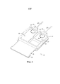
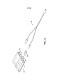
[0015] На Фиг. 1 схематически представлено пространственное изображение корпуса оптоэлектронного модуля, к которому герметично припаяны герметичные оптоволоконные узлы в соответствии с одним из вариантов воплощения данного изобретения.[0015] In FIG. 1 schematically shows a spatial image of the housing of the optoelectronic module to which hermetically sealed fiber optic nodes in accordance with one embodiment of the present invention.
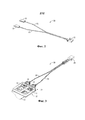
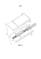
[0016] На Фиг. 2 схематически представлено пространственное изображение, иллюстрирующее оптический навесной соединительный кабель (джампер), имеющий герметичные оптоволоконные узлы, в соответствии с одним из вариантов воплощения данного изобретения.[0016] In FIG. 2 is a schematic perspective view illustrating an optical hinged patch cable (jumper) having sealed fiber optic assemblies in accordance with one embodiment of the present invention.
[0017] На Фиг. 3 схематически представлена принципиальная схема, иллюстрирующая оптический навесной соединительный кабель (джампер), показанный на Фиг. 2, с герметичным оптоволоконным узлом, герметично припаянным к корпусу оптоэлектронного модуля, в соответствии с одним из вариантов воплощения данного изобретения.[0017] FIG. 3 is a schematic diagram illustrating the optical hinged connecting cable (jumper) shown in FIG. 2, with a sealed fiber optic assembly hermetically soldered to the housing of the optoelectronic module, in accordance with one embodiment of the present invention.
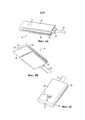
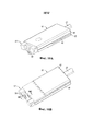
[0018] На Фиг. 4А-4С представлены пространственные изображения герметичного оптоволоконного узла в соответствии с одним из вариантов воплощения данного изобретения.[0018] FIG. 4A-4C are spatial views of a sealed fiber optic assembly in accordance with one embodiment of the present invention.
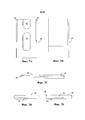
[0019] На Фиг. 5А-5С представлены горизонтальные проекции (виды в плане) герметичного оптоволоконного узла, представленного на Фиг. 4; Фиг. 5D иллюстрирует альтернативный вариант воплощения изобретения.[0019] In FIG. 5A-5C are horizontal projections (plan views) of the sealed fiber optic assembly of FIG. four; FIG. 5D illustrates an alternative embodiment of the invention.
[0020] Фиг. 6 является схематическим изображением герметичного оптоволоконного узла, показанного на Фиг. 4, с пространственно разнесенными составными частями, в соответствии с одним из вариантов воплощения данного изобретения.[0020] FIG. 6 is a schematic representation of the sealed fiber optic assembly shown in FIG. 4, with spatially spaced constituent parts, in accordance with one embodiment of the present invention.
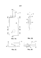
[0021] На Фиг. 7А-7Е показаны проекции (виды в плане) крышки (накладки) герметичного оптоволоконного узла[0021] In FIG. 7A-7E show projections (plan views) of a cover (patch) of a sealed fiber optic assembly
[0022] На Фиг. 8А-8Е показаны горизонтальные проекции (виды в плане) муфты герметичного оптоволоконного узла.[0022] In FIG. 8A-8E show horizontal projections (plan views) of a coupling of a sealed fiber optic assembly.
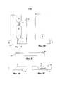
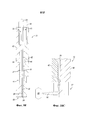
[0023] На Фиг. 9А-9Е показаны виды в разрезе вдоль линий 9А-9А до 9Е-9Е на Фиг. 5А.[0023] In FIG. 9A-9E show sectional views along
[0024] На Фиг. 10А и 10В показаны пространственные изображения направляющего свет элемента со стороны выходного торца оптических волокон в герметичном оптоволоконном узле, в соответствии с одним из вариантов воплощения данного изобретения; На Фиг. 10С показан разрез вдоль линии 10С-10С на Фиг. 10В.[0024] In FIG. 10A and 10B show spatial images of a light guiding element from the output end side of the optical fibers in a sealed fiber optic assembly, in accordance with one embodiment of the present invention; In FIG. 10C shows a section along
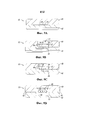
[0025] На Фиг. 11 схематически показано пространственное изображение корпуса оптоэлектронного модуля, к которому герметично припаяны герметичные оптоволоконные узлы в соответствии с другим вариантом воплощения данного изобретения.[0025] In FIG. 11 schematically shows a spatial view of an optoelectronic module housing to which sealed fiber optic assemblies are hermetically soldered in accordance with another embodiment of the present invention.
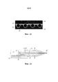
[0026] На Фиг. 12 показан фотографический вид в разрезе прототипа герметичного оптоволоконного узла.[0026] In FIG. 12 is a photographic sectional view of a prototype sealed fiber optic assembly.
[0027] На Фиг. 13 показан вид в разрезе, дополнительно иллюстрирующий детализацию крепления герметичного оптоволоконного узла к корпусу оптоэлектронного модуля в соответствии с другим вариантом воплощения данного изобретения.[0027] In FIG. 13 is a cross-sectional view further illustrating a detail of the attachment of a sealed fiber optic assembly to an optoelectronic module housing in accordance with another embodiment of the present invention.
ДЕТАЛЬНОЕ ОПИСАНИЕ ПРЕДПОЧТИТЕЛЬНЫХ ВАРИАНТОВ ВЫПОЛНЕНИЯ ИЗОБРЕТЕНИЯDETAILED DESCRIPTION OF THE PREFERRED EMBODIMENTS
[0028] Далее изобретение описано на примере различных вариантов воплощения изобретения со ссылками на сопроводительные чертежи. Несмотря на то, что изобретение описано исходя из наилучших способов воплощения, позволяющих достичь поставленных целей, специалисты оценят, что многие другие варианты и усовершенствования могут быть реализованы в рамках изобретения, без нарушения его духа и буквы.[0028] The invention will now be described by way of example various embodiments of the invention with reference to the accompanying drawings. Despite the fact that the invention is described on the basis of the best methods of embodiment, allowing to achieve the goals, experts will appreciate that many other options and improvements can be implemented within the framework of the invention, without violating its spirit and letter.
[0029] Данное изобретение предоставляет улучшенный герметичный оптоволоконный узел, который улучшает оптическую юстировку (выравнивание), технологичность, простоту использования, функциональность и надежность при сниженных затратах, таким образом преодолевая многие недостатки конструкций, известных из уровня техники.[0029] This invention provides an improved sealed fiber optic assembly that improves optical alignment, alignment, manufacturability, ease of use, functionality and reliability at reduced cost, thereby overcoming many of the disadvantages of prior art designs.
[0030] На Фиг. 1 схематично представлена принципиальная схема оптоэлектронного модуля 12, к которому герметично припаяны герметичные оптоволоконные узлы (сборки) 10 в соответствии с одним из вариантов воплощения данного изобретения. Оптоэлектронный модуль 12 включает корпус 14, который включает основание 16 и крышку, герметично припаянную (прикрепленную) к корпусу, предохраняя внутреннюю часть корпуса от окружающей среды снаружи корпуса. Для простоты крышка оптоэлектронного модуля 12 на Фиг. 1 не показана. Внутри камер в корпусе расположены оптоэлектронные устройства 17 и 18 (например, трансмиттер и ресивер и связанные с ними электронные и/или оптические элементы (отдельно не показаны на Фиг. 1, но схематично показаны на Фиг. 3). Электроника внутри оптоэлектронного модуля 12 электрически связана с внешней монтажной платой 20 с помощью гибких электрических соединительных выводов 19.[0030] In FIG. 1 schematically shows a schematic diagram of an
[0031] В иллюстрируемом варианте воплощения изобретения основание корпуса 16 включает два отверстия 21 и 22, через которые вставляют герметичные оптоволоконные узлы 10. В соответствии с одним из аспектов данного изобретения каждый герметичный оптоволоконный узел 10 служит в качестве герметичного проходного ввода для оптических волокон 24 плоского волоконно-оптического кабеля 23. В иллюстрируемом варианте воплощения изобретения в плоском волоконно-оптическом кабеле 23 имеется четыре оптических волокна 24. Герметичный оптоволоконный узел 10 также служит в качестве муфты, которая поддерживает концы (то есть участок или "концевой участок") оптических волокон 24 в фиксированном положении относительно друг друга и относительно наружных поверхностей герметичного оптоволоконного узла 10. Как будет конкретизировано далее, как только герметичный оптоволоконный узел 10 зафиксирован присоединенным к корпусу 14 (например, пайкой у отверстий (21, 22) в основании 16), концевые участки оптических волокон 24 будут зафиксированы в положении (то есть точно выровнены, отъюстированы) относительно оптоэлектронных устройств (17, 18) в корпусе 14.[0031] In the illustrated embodiment, the base of the
[0032] На Фиг. 2 схематически показана принципиальная схема, иллюстрирующая оптический навесной соединительный кабель (джампер) 30, имеющий герметичные оптоволоконные узлы 10 в соответствии с одним из вариантов воплощения данного изобретения. На Фиг. 3 схематически показана принципиальная схема, иллюстрирующая оптический навесной соединительный кабель (джампер) 30 с герметичными оптоволоконными узлами 10, герметично прикрепленными к корпусу оптоэлектронного модуля в соответствии с одним из вариантов воплощения данного изобретения. В иллюстрируемом варианте воплощения изобретения оптический навесной соединительный кабель (джампер) 30 включает два плоских волоконно-оптических кабеля 23, каждый из которых завершается на одном конце герметичным оптоволоконным узлом 10 и обычно завершается на другом конце коннектором 25 для подключения к волоконно-оптической сети. Коннектор 25 и оптоэлектронный модуль 12 могут быть частью оптоэлектронного периферийного коммутатора (платы), включающего печатную (монтажную) плату (не показана), которая поддерживает оптоэлектронный модуль 12 и коннектор 25 на кромке печатной платы. В этом случае оптический навесной соединительный кабель (джампер) 30 служит в качестве короткого оптоволоконного подсоединения от оптоэлектронного модуля 12 к встроенному выводу (то есть коннектору 25) оптоэлектронного периферийного коммутатора для внешнего подключения к волоконно-оптической сети или к коммутационной печатной плате.[0032] In FIG. 2 is a schematic diagram illustrating an optical hinged patch cable (jumper) 30 having sealed
[0033] Фиг. 4-9 иллюстрируют детализацию конструкций герметичного оптоволоконного узла 10 в соответствии с одним из вариантов воплощения данного изобретения. Герметичный оптоволоконный узел 10 является по существу узлом муфты, снабженной параллельными открытыми канавками для выравнивания концевых участков оптических волокон 24.[0033] FIG. 4-9 illustrate structural detail of a sealed
[0034] На Фиг. 4А-4С представлены пространственные изображения герметичного оптоволоконного узла 10. На Фиг. 5А-5С представлены горизонтальные проекции (виды в плане) герметичного оптоволоконного узла 10. Фиг. 6 является изображением герметичного оптоволоконного узла 10 с пространственно разнесенными составными частями. На Фиг. 9А-9Е показаны виды в разрезе вдоль линий от 9А-9А до 9Е-9Е на Фиг. 5А. В иллюстрируемом варианте воплощения изобретения узел муфты 10 содержит две части муфты, из которых первая часть муфты (называемая далее муфтой 40) снабжена канавками 34 для выравнивания оптического волокна, а вторая часть муфты (называемая далее крышкой 42) не снабжена какими-либо канавками для выравнивания. Каждая часть муфты имеет в целом плоскую структуру (по сравнению с трубкой или втулкой).[0034] FIG. 4A-4C are spatial views of a sealed
[0035] На Фиг. 7А-7Е показаны горизонтальные проекции (виды в плане) крышки 42 герметичного оптоволоконного узла 10. Как показано на Фиг. 7А, нижняя сторона 38 крышки 42 (сторона, обращенная к муфте 40) снабжена неглубокой выемкой, формирующей карман 44 вблизи центра, и выемкой 45 на одном продольном конце крышки 42. Продольные кромки снабжены фасками 46.[0035] In FIG. 7A-7E are horizontal views (plan views) of a
[0036] На Фиг. 8А-8Е показаны горизонтальные проекции муфты 40 герметичного оптоволоконного узла 10. Как показано на Фиг. 8А, нижняя сторона 39 муфты 40 (сторона, обращенная к крышке 42) снабжена неглубокой выемкой, формирующей карман 54 вблизи центра, и выемкой 55 на одном продольном конце муфты 40, стыкующейся с карманом 44 и выемкой 45. Между торцом 56 и карманом 54 предусмотрены параллельные продольные канавки 34, в горизонтальной плоскости параллельные нижней стороне 39. Дополнительные параллельные продольные канавки 35, на горизонтальной плоскости параллельные нижней стороне 39, предусмотрены между карманом 54 и выемкой 55. Как показано также на Фиг. 9Е, канавки 34 и 35 имеют такой размер, чтобы вместить завершающие концевые участки каждого оптического волокна 24 (то есть короткий участок каждого оптического волокна служит опорой оголенному концевому фрагменту с обнаженным покрытием и удаленными защитным буферным слоем и оболочкой). В частности, канавки 34 имеют прецизионно точные размеры для прецизионно точного расположения концевых участков оптических волокон 24 относительно друг друга и наружных поверхностей муфты 40. При подсоединении герметичного оптоволоконного узла 10 к корпусу 14 (например, припаиванием у отверстий (21, 22) в основании 16), концевые участки оптических волокон 24 будут зафиксированы в положении (то есть прецизионно точно выровнены, отъюстированы) относительно оптоэлектронных устройств (17, 18) в корпусе 14.[0036] In FIG. 8A-8E are horizontal views of a
[0037] Как более ясно показано на Фиг. 9Е, когда крышка 42 и муфта 40 соединены вместе, причем нижняя сторона 38 крышки 42 и нижняя сторона 39 муфты 40 находятся напротив друг друга, карманы 44 и 45 вместе задают полость 48, через которую протягивается (подвешивается) участок каждого оптического волокна 24 (то есть не касаясь муфты 40 и крышки 42). Муфта 40 снабжена отверстием 41, через которое герметизирующий состав может быть введен в полость 48. Как также показано на Фиг. 9В, ширина отверстия 41 существенно больше диаметра оптического волокна 24 и проходит через муфту, чтобы открыть (подвергнуть воздействию) все оптические волокна 24, расположенные параллельно (см. Фиг. 4С; то есть ширина отверстия 41 больше, чем все канавки 34, сгруппированные в плоскости муфты 40). Далее, выемки 45 и 55 вместе образуют карман 49, в который входит компенсатор напряжения 43, который поддерживает плоский волоконно-оптический кабель 24 (включая защитные слои над оголенными оптическими волокнами 24) на другом конце узла 10.[0037] As more clearly shown in FIG. 9E, when the
[0038] Как показано на Фиг. 8D и 9А, стенки канавок 34 задают обычно U-образную форму в поперечном сечении. Глубина каждой канавки 34 такова, чтобы полностью вместить оптическое волокно, которое не выступало бы над канавкой 34, так что верх оптического волокна по существу находится на линии с вершиной канавки (то есть по существу на том же самом уровне, что и поверхность нижней стороны 39). Когда крышка 42 и муфта 40 соединены вместе и нижняя сторона 38 крышки 42 находится напротив нижней стороны 39 муфты 40, нижняя сторона 38 крышки 42 только касается верхней части оптических волокон, поскольку она покрывает канавки 34, таким образом, удерживая оптические волокна 24 в канавках 34.[0038] As shown in FIG. 8D and 9A, the walls of the
[0039] Канавки 34 структурированы, чтобы надежно удерживать оптические волокна 24 (оголенный участок с обнаженным покрытием, без защитного буферного слоя и оболочек), зажимая оптические волокна 24, например, с помощью механической посадки или посадки с натягом (или прессовой посадки). Например, ширина канавок 34 может быть по размеру несколько меньше, чем диаметр оптических волокон 24, так что оптические волокна 24 плотно удерживаются в канавках 34 за счет посадки с натягом. Посадка с натягом гарантирует, что оптические волокна 24 зажимаются (защелкиваются) на месте, и, следовательно, положение и ориентация концевых участков оптических волокон 24 задаются положением и продольной осью канавок 34. В иллюстрируемом варианте воплощения изобретения канавки 34 в сечении имеют U-образную форму и плотно удерживают оголенные оптические волокна 24 (то есть с обнаженным покрытием, без защитного буферного слоя и оболочки). Боковые стенки канавки 34 практически параллельны, а отверстие (просвет) канавок может быть немного уже, чем параллельный зазор между боковыми стенками (то есть со слегка сообразным поперечным сечением), чтобы обеспечить дополнительную механическую посадку или посадку с натягом для оптических волокон 24. Более подробная информация о структуре открытой канавки может быть найдена в одновременно рассматриваемой заявке на патент США №13/440,970, поданной 5 апреля 2012, которая полностью включена в данную заявку в виде ссылки. Муфта 40, снабженная канавками 34, является практически неразъемной открытой муфтой, поддерживающей оптические волокна 24 с их концевыми участками, прецизионно точно расположенными и выровненными друг относительно друга и по отношению к внешней конфигурации муфты 40.[0039] The
[0040] Канавки 34 в поперечном сечении могут иметь закругленное дно (см. Фиг. 9А), которое будет конформно контактировать с половиной цилиндрической стенки (то есть полуокружностью цилиндрической стенки) оптических волокон. В любом случае стенки оптических волокон 24 будут контактировать (например, сжимающим контактом), по крайней мере, с боковыми стенками канавок 34, причем, по крайней мере, боковые стороны оптических волокон будут находиться в плотном контакте (например, по существу тангенциальном контакте в поперечном сечении) с боковыми стенками канавок 34. Такой боковой контакт между оптическими волокнами и прилегающими боковыми стенками канавок 34 гарантирует конфигурацию, которая задает необходимое горизонтальное выравнивание (юстировку) расположения/ интервала оптических волокон 24 друг относительно друга и относительно, по крайней мере, боковых сторон муфты 40. Точная калибровка глубины канавок 34 в муфте 40 гарантирует конфигурацию относительно крышки 42, которая задает необходимое выравнивание (юстировку) оптических волокон 24 по вертикали относительно, по крайней мере, наружной поверхности (верхней поверхности, противоположной нижней стороне 39) муфты 40.[0040] The
[0041] Что касается канавок 35 для удерживания участков оптических волокон 24, продолжающихся далее от концов оптических волокон 24 на другую сторону полости 48, они могут иметь аналогичную геометрию и/или конструктивные особенности, как и канавки 34. Однако отмечено, что для оптической юстировки (выравнивания) оптических волокон необходимо просто обеспечить выравнивание канавок 34 с жестким допуском для удерживания концевых участков оптических волокон 24. Канавки 35, предусмотренные ближе к компенсатору напряжения 43, не должны иметь такой строгий допуск, как канавки 34, поскольку допуск канавок не влияет на оптическое выравнивание концевых участков оптических волокон 24 относительно внешнего оптического компонента.[0041] As for the
[0042] Герметичное уплотнение узла 10 может быть реализовано с помощью следующей процедуры в соответствии с одним вариантом воплощения данного изобретения. Оптические волокна 24 с удаленными с концевых участков защитным буферным слоем и оболочкой размещают в канавки 34 и 35 в муфте 40. Крышку 42 присоединяют к муфте (например, с помощью внешнего защелкивающего зажима) в конфигурации, показанной в целом на Рис. 9Е. Крышку 42 и муфту 40 припаивают друг к другу, используя золото-оловянный припой. Фаска 46 обеспечивает некоторый зазор, позволяя избыточному припою выходить (растекаться). Заметим, что фаска 46, как показано, не простирается по всей длине крышки 42, чтобы уменьшить потенциальный зазор с целью облегчить припаивание узла 10 к корпусу модуля 14.[0042] The hermetic seal of
[0043] Как также показано на Рис. 13, герметик 37, такой как стеклянный припой (или другой герметизирующий состав, подходящий для герметичного уплотнения) подают через отверстие 41 в муфте 40, в то время как вакуум подают к карману 49, таким образом, втягивая стеклянный припой, чтобы заполнить полость 48 и доступные пространства/зазор между оптическими волокнами 23, канавками 35 и крышкой 42, принимая, что канавки в целом имеют U-образную форму в поперечном сечении (см. Фиг. 13). Часть стеклянного припоя также перетекает, заполняя доступные пространства между оптическими волокнами, выравнивающими канавками 34 и крышкой 42. Необязательно втягивать стеклянный припой полностью через канавки 34 или 35 до тех пор, пока есть достаточное количество герметика, поступающего на достаточное расстояние, чтобы заполнить доступные пространства, по крайней мере, в области около входа из полости в соответствующие канавки. Учитывая, что карманы 44 и 54 имеют глубины больше, чем глубины канавок 34 и 35, герметик охватывает участки оптических волокон 24, подвешенные в полости 48. Герметик по существу формирует герметичную пробку в полости 48, ограничивая утечку через узел 10. Конструкция узла 10 может быть герметично уплотнена, не требуя какой-либо внешней муфты помимо двух частей муфты (муфты 40 и крышки 42 в описанном выше варианте воплощения изобретения). Конструкция герметичного узла, таким образом, очень проста и обеспечивает эффективное герметичное уплотнение.[0043] As also shown in Fig. 13, a
[0044] Следует отметить, что при условии плотного контакта между стенками оптических волокон и стенками, по крайней мере, канавок 34, герметик не поступает между контактирующими поверхностями, имеющимися между оптическими волокнами 24, крышкой 42 и стенками канавок 34, существующими еще до применения герметика. Это означает, что герметик закупоривает доступные пространства и/или зазор между оптическими волокнами 24, канавками 34 и крышкой 42, но не формирует промежуточный слой между оптическими волокнами и стенками канавок в точках контакта, существующих до применения герметика, который, в противном случае, мог бы повлиять на выравнивание оптических волокон канавками 34.[0044] It should be noted that under the condition of tight contact between the walls of the optical fibers and the walls of at least the
[0045] После герметизации с помощью стеклянного припоя в карман 49 вводят эпоксидную смолу, чтобы сформировать компенсатор напряжения 43. В качестве окончательной обработки герметичного узла 10 оголенные концевые участки оптических волокон 24 могут быть отполированы, чтобы быть в значительной степени копланарными (лежать в одной плоскости) переднему торцу 56 муфты 40. Концевые участки волокон 24 могут немного выступать (самое большее на несколько микрон) за пределы торца 56 муфты 40, но не выходить слишком сильно за пределы торца 56, потому что на соответствующих концевых участках оптических волокон 24 нет защитного буферного слоя и оболочки. Для облегчения припаивания узла к корпусу модуля 14 и для улучшения антикоррозийной стойкости, поверхности крышки 42 и/или муфты 40 могут быть покрыты золотом.[0045] After sealing with glass solder, an epoxy resin is introduced into
[0046] В соответствии с одним аспектом данного изобретения муфта 40 и/или крышка 42 могут быть сформированы прецизионной штамповкой металлического материала. Согласно одному варианту выполнения изобретения металлический материал может быть выбран таким образом, чтобы обладать высокой жесткостью (например, нержавеющая сталь), химической инертностью (например, титан), высокой термостабильностью (никелевый сплав), малым коэффициентом термического расширения (например, инвар) или соответствовать коэффициенту термического расширения других материалов (например, ковар для соответствия стеклу). В качестве альтернативы, материалом может быть кремний, твердая пластмасса или другой твердый полимерный материал.[0046] In accordance with one aspect of the present invention, the
[0047] Раскрытая выше открытая структура муфты 40 и крышки 42 позволяет производить их с помощью процессов массового производства, таких как штамповка, которые являются низкозатратными высокопроизводительными процессами. Способ и устройство для прецизионной штамповки были раскрыты в патенте США №7343770, права на который были переданы правообладателю данного изобретения. Этот патент полностью включен в данную заявку в виде ссылки. Способ и устройство для штамповки, раскрытые в этом патенте, могут быть адаптированы для прецизионной штамповки муфты 40 и крышки 42 по данному изобретению. Процесс штамповки и устройство дают возможность производить детали с допуском, по крайней мере, 1000 нм.[0047] The open structure of the
[0048] Фиг. 5D иллюстрирует альтернативный вариант воплощения изобретения, в котором комплементарные выравнивающие канавки 34' и 34" (например, канавки, имеющие С-образное или полукруглое поперечное сечение) предусмотрены на частях муфты 40' и 42' соответственно. Канавки 34' и 34" могут быть симметричными или асимметричными относительно поверхности контакта между частями муфты 40' и 42" на виде с торца, приведенном на Фиг. 5D (или виде в разрезе, ортогональном к продольной оси канавок). В альтернативном варианте воплощения изобретения части муфты 40' и 42" могут быть идентичными. Альтернативно, вместо канавок U-образной формы или канавок С-образной формы в муфте 40, крышке 42 и/или частях муфты 40' и 42' можно использовать канавки, имеющие V-образную форму в поперечном сечении.[0048] FIG. 5D illustrates an alternative embodiment of the invention in which
[0049] Вместо создания отверстия для подачи стеклянного припоя в муфте 40, такое отверстие может быть предусмотрено в крышке 42 взамен или в качестве дополнения. Далее, полость 48 может быть задана карманом, предусмотренным только в одном из: либо в муфте 40, либо в крышке 42. В качестве альтернативы, вместо углублений, задающих карманы 44 и 54, канавки существенного большего размера могут быть предусмотрены в крышке 42 и/или в муфте 40, соединяя канавки 34 и 35 (то есть большие зазоры между оптическими волокнами 24 и канавками большего размера для облегчения течения герметика, чтобы герметично закупорить узел изнутри).[0049] Instead of creating a hole for supplying glass solder in the
[0050] В то время как вышеупомянутые варианты воплощения изобретения направлены на герметичный узел муфты для многоволоконного оптического кабеля, концепция данного изобретения также применима к герметичному узлу моноволоконной муфты.[0050] While the aforementioned embodiments of the invention are directed to a sealed clutch assembly for a multi-fiber optical cable, the concept of the present invention also applies to a sealed monofilament coupling assembly.
[0051] На Фиг. 10А и 10В представлены пространственные изображения направляющего свет элемента на концевых участках оптических волокон 24 в герметичном оптоволоконном узле 10, обсуждавшемся выше; Фиг. 10С представляет собой вид в разрезе вдоль линии 10С-10С на Фиг. 10В. Отдельный зеркальный узел 57 (показан схематично) располагают и выравнивают (юстируют) относительно торцов оптических волокон 24, чтобы направлять световой поток входа/выхода между торцами волокон и оптоэлектронным устройством 58 (показано схематично), таким как трансмиттер (например, лазер, такой как VCSEL - поверхностно-излучающий лазер с вертикальным резонатором) или ресивер (например, фото детектор). Эти оптоэлектронные устройства конвертируют электрические сигналы в оптические сигналы и наоборот и находятся в оптоэлектронном модуле 12. На Фиг. 13 показан вид в разрезе, дополнительно детализирующий установку герметичного оптоволоконного узла через отверстия (21, 22) в основании 16 корпуса оптоэлектронного модуля 14 в соответствии с другим вариантом воплощения данного изобретения.[0051] In FIG. 10A and 10B show spatial images of a light guide element at end portions of
[0052] Зеркальный узел 57 может быть присоединен к узлу 10, а ввод/вывод зеркального узла 57 располагают и выравнивают (юстируют) относительно оптоэлектронного устройства 58. Альтернативно, зеркальный узел 57 фиксируют внутри модуля 12 и выравнивают относительно оптоэлектронного устройства 58 с герметичным узлом 10, выровненным относительно зеркального узла 57. Как также показано на Фиг. 3, герметичный узел 10 герметично припаян к основанию 16 корпуса модуля. Можно полагать, что герметичный узел 10 может функционировать и как проходное устройство, и как выравнивающая (юстировочная) муфта для плоского волоконно-оптического кабеля 23.[0052] The
[0053] В то время как описанные выше варианты воплощения изобретения описаны применительно к герметичному узлу муфты, имеющему в целом прямоугольное поперечное сечение, другая конфигурация поперечного сечения может быть реализована без нарушения духа и буквы данного изобретения.[0053] While the above-described embodiments of the invention are described with reference to a sealed coupling assembly having a generally rectangular cross-section, another cross-sectional configuration can be implemented without violating the spirit and letter of the present invention.
[0054] Как показано в варианте воплощения изобретения, проиллюстрированном на Фиг. 11, герметичный узел муфты может иметь в целом овальное поперечное сечение. Конструкция герметичного узла 60 может быть аналогична герметичному узлу 10 согласно описанным выше вариантам воплощения изобретения, за исключением того, что внешний профиль поперечного сечения является в целом овальным. Герметичный узел 60 включает две части муфты, которые вместе составляют герметичный узел, имеющий овальное поперечное сечение. Одна из частей муфты может соответствовать крышке 42 в предшествующем варианте воплощения изобретения (имея характеристики поверхности, аналогичные нижней стороне 38), а другая часть муфты может соответствовать муфте 40 в предшествующем варианте воплощения изобретения (имея характеристики поверхности, аналогичные нижней стороне 39). В этом варианте воплощения изобретения вместо того чтобы соединять герметичный узел муфты с плоским оптоволоконным кабелем 23, как в предшествующих вариантах воплощения изобретения, герметичный узел муфты 60 герметично присоединен к корпусу 14 оптоэлектронного модуля 12, имеющему оптические волокна, находящиеся внутри узла 60 и не выступающие заметно с обоих концов за пределы узла 60 (то есть оптические волокна, находящиеся в узле 60, завершаются по существу копланарно с обоими торцами узла 60; один из торцов узла 60 находится внутри корпуса модуля 14). Альтернативно, овальный герметичный узел, показанный на Фиг. 11, может быть заменен герметичным узлом 10 согласно предшествующему варианту воплощения изобретения; в этом случае потребуется выравнивающая втулка, имеющая в целом прямоугольное поперечное сечение.[0054] As shown in the embodiment of the invention illustrated in FIG. 11, the sealed coupling assembly may have a generally oval cross-section. The design of the sealed
[0055] Соответственно, в этом варианте воплощения изобретения герметичный узел муфты 60 обеспечивает разборную (съемную) концевую муфту для модуля 12 для присоединения к другому оптическому устройству, такому как плоский оптоволоконный кабель (например, соединительный шнур 63, имеющий муфты аналогичной формы с овальным поперечным сечением), используя выравнивающую втулку 62 (например, разрезную (разъемную) втулку, имеющую комплементарную форму и размер, чтобы вместить узел муфты 60 и муфту на соединительном кабеле 63). Можно полагать, что в этом варианте воплощения изобретения герметичный узел 60 является герметичной концевой муфтой модуля 12, имеющей выравнивающую муфту для оптического выравнивания (юстировки) с внешними устройствами. С этим вариантом воплощения изобретения дефектный внешний плоский оптоволоконный кабель может быть заменен путем подключения (заделывания) заменяющего плоского кабеля к герметичной концевой муфте.[0055] Accordingly, in this embodiment, the sealed
[0056] Для описанных выше герметичных узлов, которые скомпонованы для оптического выравнивания/стыковки с оптическими волокнами другого плоского оптоволоконного кабеля, наружные поверхности герметичных узлов должны быть выдержаны с жестким допуском, также как для выравнивания с использованием центрирующей втулки. В вариантах воплощения изобретения, описанных выше, не требуется каких-либо центрирующих штырей для выравнивания муфт. Соответственно, для штамповки частей муфты (муфт и крышек), которая будет включать штамповку всего корпуса частей муфты, включая формирование канавок, стыкующихся поверхностей частей муфты и наружных поверхностей, которые контактируют с втулками. Втулки также могут быть прецизионно сформированы штамповкой. Это обеспечивает требуемую пространственную взаимосвязь между канавками и внешними выравнивающими поверхностями герметичных узлов, чтобы облегчить выравнивание (юстировку), используя только центрирующие (выравнивающие) втулки, не полагаясь на установочные (центрирующие) штыри.[0056] For the sealed assemblies described above, which are arranged for optical alignment / docking with optical fibers of another flat fiber optic cable, the outer surfaces of the sealed assemblies must be maintained with a tight tolerance, as well as for alignment using a centering sleeve. In the embodiments of the invention described above, no centering pins are required to align the couplings. Accordingly, for stamping the coupling parts (couplings and covers), which will include stamping the entire housing of the coupling parts, including forming grooves, mating surfaces of the coupling parts and the outer surfaces that are in contact with the bushings. The bushings can also be precision formed by stamping. This provides the required spatial relationship between the grooves and the external alignment surfaces of the sealed units to facilitate alignment (alignment) using only centering (alignment) bushings, not relying on the mounting (centering) pins.
[0057] Герметичный узел для выравнивания оптического волокна в соответствии с данным изобретением преодолевает многие недостатки существующего уровня техники, обеспечивая прецизионное выравнивание, высокую устойчивость к условиям окружающей среды, и может быть произволен с низкими затратами. Заявляемый герметичный узел может быть скомпонован для удерживания одного или множества волокон, для оптического выравнивания и/или в качестве герметичного проходного элемента.[0057] The sealed optical fiber alignment assembly of the present invention overcomes many of the disadvantages of the prior art, providing precision alignment, high environmental resistance, and can be arbitrarily cost-effective. The inventive sealed unit may be arranged to hold one or multiple fibers, for optical alignment and / or as a sealed passage element.
[0058] Несмотря на то, что изобретение описано исходя из предпочтительных вариантов воплощения, специалистам очевидно, что многие другие изменения по форме и в деталях могут быть реализованы в рамках изобретения, без нарушения его духа и буквы. Соответственно, раскрытое изобретение следует рассматривать лишь как иллюстрацию, в то время как сущность изобретения ограничена только приведенной далее Формулой изобретения.[0058] Although the invention has been described on the basis of preferred embodiments, it will be apparent to those skilled in the art that many other changes in form and detail can be realized within the scope of the invention without violating its spirit and letter. Accordingly, the disclosed invention should be considered only as an illustration, while the essence of the invention is limited only by the following claims.
Claims (38)
Applications Claiming Priority (5)
| Application Number | Priority Date | Filing Date | Title |
|---|---|---|---|
| US201261623027P | 2012-04-11 | 2012-04-11 | |
| US61/623,027 | 2012-04-11 | ||
| US201261699125P | 2012-09-10 | 2012-09-10 | |
| US61/699,125 | 2012-09-10 | ||
| PCT/US2013/036228 WO2014011282A2 (en) | 2012-04-11 | 2013-04-11 | Hermetic optical fiber alignment assembly |
Publications (1)
| Publication Number | Publication Date |
|---|---|
| RU2647212C1 true RU2647212C1 (en) | 2018-03-14 |
Family
ID=49517621
Family Applications (2)
| Application Number | Title | Priority Date | Filing Date |
|---|---|---|---|
| RU2014144532A RU2638979C1 (en) | 2012-04-11 | 2013-04-11 | Hermetic assembly for alignment of optical fibre, which has integrated optical element |
| RU2014144530A RU2647212C1 (en) | 2012-04-11 | 2013-04-11 | Sealed assembly for optical fiber alignment |
Family Applications Before (1)
| Application Number | Title | Priority Date | Filing Date |
|---|---|---|---|
| RU2014144532A RU2638979C1 (en) | 2012-04-11 | 2013-04-11 | Hermetic assembly for alignment of optical fibre, which has integrated optical element |
Country Status (11)
| Country | Link |
|---|---|
| US (3) | US9213148B2 (en) |
| EP (2) | EP2836865B1 (en) |
| JP (3) | JP2015513125A (en) |
| KR (2) | KR20140146647A (en) |
| CN (2) | CN104335089B (en) |
| AU (2) | AU2013289173B2 (en) |
| BR (1) | BR112014025229A2 (en) |
| CA (2) | CA2869678A1 (en) |
| MX (2) | MX337478B (en) |
| RU (2) | RU2638979C1 (en) |
| WO (2) | WO2014011282A2 (en) |
Families Citing this family (27)
| Publication number | Priority date | Publication date | Assignee | Title |
|---|---|---|---|---|
| DK2823344T3 (en) * | 2012-03-05 | 2019-05-20 | Nanoprecision Products Inc | CONNECTING DEVICE WHICH HAS A STRUCTURED REFLECTIVE SURFACE TO CONNECT INPUT / OUTPUT OF AN OPTICAL FIBER |
| US9235014B2 (en) * | 2013-07-31 | 2016-01-12 | Avago Technologies General Ip (Singapore) Pte. Ltd. | Optics system module for use in an optical communications module, an optical communications system, and a method |
| EP2916151B1 (en) | 2014-03-05 | 2020-01-01 | Corning Optical Communications LLC | Method of forming a fiber coupling device |
| US9874704B2 (en) | 2014-08-13 | 2018-01-23 | Finisar Corporation | Ferrule assemblies |
| US9612414B2 (en) | 2014-08-13 | 2017-04-04 | Finisar Corporation | Multi-channel optoelectronic subassemblies |
| US9804349B2 (en) | 2014-08-13 | 2017-10-31 | Finisar Corporation | Multi-lens optical components |
| US9854687B2 (en) | 2014-08-13 | 2017-12-26 | Finisar Corporation | Multi-layer substrates including thin film signal lines |
| US9848498B2 (en) | 2014-08-13 | 2017-12-19 | Finisar Corporation | Optoelectronic subassembly with components mounted on top and bottom of substrate |
| JP6357588B2 (en) * | 2014-10-28 | 2018-07-11 | フィニサー コーポレイション | Multi-channel optoelectronic subassembly and method |
| JP6898245B2 (en) * | 2015-03-22 | 2021-07-07 | ナノプレシジョン プロダクツ インコーポレイテッドNanoprecision Products, Inc. | Optical bench subassembly with integrated optical device |
| WO2016154233A1 (en) | 2015-03-22 | 2016-09-29 | Nanoprecision Products, Inc. | Axial preload for demountable connectors |
| WO2017027864A1 (en) * | 2015-08-12 | 2017-02-16 | Nanoprecision Products, Inc. | Multiplexer/demultiplexer using stamped optical bench with micro mirrors |
| US11573377B2 (en) * | 2015-10-12 | 2023-02-07 | 3M Innovative Properties Company | Optical waveguide positioning feature in a multiple waveguides connector |
| US9880366B2 (en) | 2015-10-23 | 2018-01-30 | Nanoprecision Products, Inc. | Hermetic optical subassembly |
| US9706670B1 (en) | 2015-12-31 | 2017-07-11 | International Business Machines Corporation | Connecting mid-board electronic devices |
| WO2017161061A1 (en) * | 2016-03-15 | 2017-09-21 | Nanoprecision Products, Inc. | Optical alignment of an optical subassembly to an optoelectronic device |
| US10241268B2 (en) * | 2016-04-08 | 2019-03-26 | Acacia Communications, Inc. | Filling a cavity through a reservoir and a feed-channel and related apparatus and methods |
| CN107918174A (en) * | 2016-10-11 | 2018-04-17 | 康普技术有限责任公司 | Ferrule assembly, the method and optical fiber fixing mould for manufacturing ferrule assembly |
| US10416381B1 (en) | 2016-12-23 | 2019-09-17 | Acacia Communications, Inc. | Spot-size-converter design for facet optical coupling |
| US10559408B2 (en) | 2016-12-27 | 2020-02-11 | Asml Netherlands B.V. | Feedthrough device and signal conductor path arrangement |
| US10008362B1 (en) | 2016-12-27 | 2018-06-26 | Mapper Lithography Ip B.V. | Optical fiber feedthrough device and fiber path arrangement |
| US10481344B2 (en) | 2017-11-21 | 2019-11-19 | Lumentum Operations Llc | High density optical fiber feedthrough |
| CN108761666A (en) * | 2018-03-30 | 2018-11-06 | 武汉联特科技有限公司 | A kind of optical module |
| WO2021165721A1 (en) * | 2020-02-18 | 2021-08-26 | Osensa Innovations Corp. | Optical fiber receptacle |
| US11280968B2 (en) | 2020-02-21 | 2022-03-22 | International Business Machines Corporation | High-bandwidth embedded optical connector with latching mechanism |
| US20220196941A1 (en) * | 2020-12-17 | 2022-06-23 | Intel Corporation | Completely encapsulated optical multi chip package |
| CN115407463A (en) * | 2021-05-26 | 2022-11-29 | 索尔思光电股份有限公司 | Optical device and assembling method thereof |
Citations (3)
| Publication number | Priority date | Publication date | Assignee | Title |
|---|---|---|---|---|
| EP1308760A1 (en) * | 2001-11-01 | 2003-05-07 | Samsung Electronics Co., Ltd. | Fibre array with V-groove substrate and cover press plate |
| US20060244118A1 (en) * | 2001-01-31 | 2006-11-02 | Gentex Corporation | High power radiation emitter device and heat dissipating package for electronic components |
| US20070172175A1 (en) * | 2006-01-26 | 2007-07-26 | Talapker Imanbayev | Hermetic fiber optic ferrule |
Family Cites Families (82)
| Publication number | Priority date | Publication date | Assignee | Title |
|---|---|---|---|---|
| DE2528270C3 (en) * | 1975-06-25 | 1978-12-14 | Felten & Guilleaume Carlswerk Ag, 5000 Koeln | Method for producing a coupling for optical fibers |
| FR2426347A1 (en) * | 1978-05-18 | 1979-12-14 | Thomson Csf | SEMICONDUCTOR LASER SOURCE AND ITS MANUFACTURING PROCESS |
| US4413881A (en) | 1979-07-26 | 1983-11-08 | Northern Telecom Limited | Optical fiber hermetic seal |
| DE3408783A1 (en) * | 1983-08-03 | 1985-02-14 | Siemens AG, 1000 Berlin und 8000 München | CONNECTING ELEMENT FOR LIGHTWAVE GUIDE AND METHOD FOR PRODUCING THE SAME |
| DE3807491A1 (en) | 1988-03-08 | 1989-09-21 | Schott Glaswerke | METHOD AND DEVICE FOR HERMETICALLY CARRYING OUT A LIGHT WAVE GUIDE |
| US5029968A (en) * | 1990-03-05 | 1991-07-09 | Hughes Aircraft Company | Optoelectronic hybrid package assembly including integral, self-aligned fiber optic connector |
| JP3068889B2 (en) * | 1991-06-25 | 2000-07-24 | 京セラ株式会社 | Optical fixed attenuator |
| RU2051394C1 (en) * | 1992-04-13 | 1995-12-27 | Александр Васильевич Костюнин | Device for mating fiber lightguide with irradiator |
| JPH0735958A (en) * | 1993-07-23 | 1995-02-07 | Sumitomo Electric Ind Ltd | Parallel transmission module |
| AU668031B2 (en) * | 1993-03-31 | 1996-04-18 | Sumitomo Electric Industries, Ltd. | Optical fiber array |
| JP2616668B2 (en) * | 1993-08-30 | 1997-06-04 | 日本電気株式会社 | Hermetically sealed structure of optical fiber introduction section |
| US5389312A (en) * | 1993-10-26 | 1995-02-14 | Motorola, Inc. | Method of fabricating molded optical waveguides |
| JPH07249798A (en) * | 1994-03-09 | 1995-09-26 | Fujitsu Ltd | Optical device securing apparatus and its manufacture |
| US5602951A (en) * | 1994-04-14 | 1997-02-11 | Sumitomo Electric Industries, Ltd. | Ferrule for optical connector and process for making same |
| JP2614018B2 (en) * | 1994-06-29 | 1997-05-28 | 日本電気エンジニアリング株式会社 | Hermetic sealing structure and hermetic sealing method for optical fiber introduction section |
| US5500910A (en) * | 1994-06-30 | 1996-03-19 | The Whitaker Corporation | Passively aligned holographic WDM |
| JP3276787B2 (en) * | 1994-10-07 | 2002-04-22 | 古河電気工業株式会社 | Ferrule manufacturing method |
| JPH11502633A (en) * | 1995-01-18 | 1999-03-02 | ローベルト ボツシユ ゲゼルシヤフト ミツト ベシユレンクテル ハフツング | Converter for converting optical signal to electric signal and method for manufacturing the same |
| US5778123A (en) * | 1996-03-12 | 1998-07-07 | Minnesota Mining And Manufacturing Company | Alignment assembly for multifiber or single fiber optical cable connector |
| US5786002A (en) * | 1996-04-04 | 1998-07-28 | Siecor Corporation | Guide block assembly for aligning bore forming pins during molding of multi-fiber optical connector ferrules |
| US5815621A (en) * | 1996-05-23 | 1998-09-29 | Sumitomo Electric Industries, Ltd. | Optical fiber connector ferrule with die and method of manufacturing same |
| KR19980042931A (en) * | 1996-11-29 | 1998-08-17 | 쿠라우찌 노리타카 | Optical module and manufacturing method thereof, optical reflecting member of optical module, positioning method and positioning device |
| JP3758258B2 (en) * | 1996-11-29 | 2006-03-22 | 富士通株式会社 | Optical coupling device |
| JP4061682B2 (en) * | 1996-12-27 | 2008-03-19 | 住友電気工業株式会社 | Method for forming optical connector ferrule |
| JPH10197761A (en) * | 1997-01-09 | 1998-07-31 | Ngk Insulators Ltd | Thermally fused and integrated ferrule and its production |
| JP3064969B2 (en) * | 1997-07-03 | 2000-07-12 | 日本電気株式会社 | Light receiving module and manufacturing method thereof |
| JPH11119064A (en) * | 1997-10-17 | 1999-04-30 | Fujitsu Ltd | Optical transmission terminal device |
| JPH11160544A (en) * | 1997-11-28 | 1999-06-18 | Kyocera Corp | Optical attenuator and manufacture thereof |
| KR100340665B1 (en) * | 1997-12-31 | 2002-09-25 | 주식회사 머큐리 | Ultra-multiconnector ferrule for optical connector and method of inserting optical fiber in the same |
| JP3997710B2 (en) | 1998-08-07 | 2007-10-24 | 住友電気工業株式会社 | Ferrule for optical connector, mold for molding, manufacturing method for ferrule for optical connector, and inspection method for ferrule for optical connector |
| TW416014B (en) * | 1999-03-05 | 2000-12-21 | Ind Tech Res Inst | Production method of multi-fiber optical connector ferrules and forming mold |
| US6296400B1 (en) * | 1999-05-19 | 2001-10-02 | Trw Inc. | Integrated fiber optic bulkhead receptacle |
| US6264375B1 (en) * | 1999-10-05 | 2001-07-24 | Sumitomo Electric Industries, Ltd. | Fiber optic connector ferrule and method of making the same |
| US6456766B1 (en) | 2000-02-01 | 2002-09-24 | Cornell Research Foundation Inc. | Optoelectronic packaging |
| CA2334733A1 (en) * | 2000-03-09 | 2001-09-09 | Douglas Stephen Burbidge | A hermetic fiber optic package and a method of manufacturing same |
| US6409394B1 (en) * | 2000-03-21 | 2002-06-25 | Sumitomo Electric Industries, Ltd. | Optical connector |
| US6793403B2 (en) * | 2000-12-15 | 2004-09-21 | The Furukawa Electric Co., Ltd. | Method of producing ferrule and ferrule |
| WO2002057821A1 (en) * | 2001-01-19 | 2002-07-25 | Primarion, Inc. | Optical interconnect with integral reflective surface and lens, system including the interconnect and method of forming the same |
| US20050201711A1 (en) * | 2001-01-22 | 2005-09-15 | Koh Philip J. | Packaging and interconnect system for fiber and optoelectric components |
| US20020110328A1 (en) * | 2001-02-14 | 2002-08-15 | Bischel William K. | Multi-channel laser pump source for optical amplifiers |
| US20020146215A1 (en) * | 2001-03-16 | 2002-10-10 | Takahiro Ogawa | Double-sided ferrule manufacturing method, auxiliary member used therein, end surface polishing method for double-sided ferrule, optical connector assembling method, optical connector, guide pin, and optical connector connecting method using the same |
| US6550980B2 (en) * | 2001-04-05 | 2003-04-22 | Stratos Lightwave, Inc. | Optical ferrule having multiple rows of multiple optical fibers |
| JP2002303761A (en) * | 2001-04-06 | 2002-10-18 | Furukawa Electric Co Ltd:The | Multi-fiber optical connector ferrule and method for manufacturing multi-fiber optical connector |
| US6643446B2 (en) | 2001-11-27 | 2003-11-04 | Jds Uniphase Inc. | Hermetic fiber ferrule and feedthrough |
| DE60239422D1 (en) * | 2001-11-29 | 2011-04-21 | Sumitomo Electric Industries | Method and metal mold for producing the guide sleeve of an optical connector |
| DE10159093C1 (en) * | 2001-12-01 | 2003-08-14 | Schott Glas | Process for the hermetic injection of an optical fiber into a metal bushing and hermetic injection produced thereafter |
| JP2003207694A (en) * | 2002-01-15 | 2003-07-25 | Nec Corp | Optical module |
| US20030142920A1 (en) * | 2002-01-28 | 2003-07-31 | Dallas Joseph L. | Method and apparatus for optical fiber array assembly |
| GB0201969D0 (en) | 2002-01-29 | 2002-03-13 | Qinetiq Ltd | Integrated optics devices |
| US6910808B2 (en) * | 2002-02-14 | 2005-06-28 | The Furukawa Electric Co., Ltd. | Optical connector ferrule for supporting an optical fiber tape conductor, optical connector, method for assembling an optical connector and optical fiber inserting jig |
| JP3748065B2 (en) | 2002-02-14 | 2006-02-22 | 住友電気工業株式会社 | Optical fiber array |
| FR2836236B1 (en) | 2002-02-21 | 2004-09-17 | Framatome Connectors Int | IMPROVED OPTOELECTRONIC COUPLING DEVICE |
| US6913397B2 (en) * | 2002-03-04 | 2005-07-05 | Xanoptix, Inc. | Method and system for insertion of fibers of a fiber cable into a ferrule |
| KR100461157B1 (en) * | 2002-06-07 | 2004-12-13 | 한국전자통신연구원 | Parallel optical interconnect module and method for manufacturing thereof |
| WO2004017114A1 (en) | 2002-08-16 | 2004-02-26 | Oz Optics Limited | Stress relief in fibre optic arrays |
| US7311449B2 (en) * | 2002-08-16 | 2007-12-25 | Nanoprecision Products, Inc. | High precision optoelectronic components |
| US7343770B2 (en) * | 2002-08-16 | 2008-03-18 | Nanoprecision Products, Inc. | Stamping system for manufacturing high tolerance parts |
| US6920276B2 (en) | 2002-08-26 | 2005-07-19 | Seikoh Giken Co., Ltd. | Optical fiber assembly having hermetic seal portion and method for making the same |
| JP3947481B2 (en) * | 2003-02-19 | 2007-07-18 | 浜松ホトニクス株式会社 | Optical module and manufacturing method thereof |
| US20060193565A1 (en) | 2003-02-20 | 2006-08-31 | Kyoichi Sasaki | Optical transmission medium connecting method, optical connecting structure, and optical transmission medium connecting part |
| JP2004309540A (en) * | 2003-04-02 | 2004-11-04 | Nippon Telegr & Teleph Corp <Ntt> | Multi-channel optical communication module |
| US7186031B2 (en) * | 2003-10-16 | 2007-03-06 | 3M Innovative Properties Company | Optical interconnect device |
| JP2006017831A (en) * | 2004-06-30 | 2006-01-19 | Fuji Photo Film Co Ltd | Injection molding die for light guiding body, and manufacturing apparatus |
| US7189007B2 (en) * | 2005-02-09 | 2007-03-13 | Tektronix, Inc. | Termination for optic fiber |
| CA2639102A1 (en) | 2007-08-23 | 2009-02-23 | Oz Optics Ltd. | Method of producing hermetically-sealed optical fibers and cables with highly controlled and complex layers |
| JP5186875B2 (en) | 2007-10-12 | 2013-04-24 | 日亜化学工業株式会社 | Lighting unit |
| US7726885B2 (en) * | 2007-10-29 | 2010-06-01 | Fujikura Ltd. | Optical connector having a fitting protrusion or fitting recess used for positioning |
| CN101981482B (en) | 2008-03-28 | 2013-03-13 | 惠普发展公司,有限责任合伙企业 | Flexible optical interconnect |
| CN101943773B (en) * | 2009-07-07 | 2013-11-27 | 3M中国有限公司 | Micro-connecting disk |
| WO2011044090A2 (en) * | 2009-10-09 | 2011-04-14 | Corning Incorporated | Integrated silicon photonic active optical cable components, sub-assemblies and assemblies |
| CN102859410B (en) * | 2009-11-03 | 2015-07-08 | 3M创新有限公司 | Fiber optic devices and methods of manufacturing fiber optic devices |
| US8342756B2 (en) | 2009-12-22 | 2013-01-01 | Jds Uniphase Corporation | Hermetic seal between a package and an optical fiber |
| US8277130B2 (en) * | 2009-12-23 | 2012-10-02 | Fujikura Ltd. | Optical connector with reflector |
| US8215850B2 (en) | 2009-12-29 | 2012-07-10 | Prasad Yalamanchili | Optical module with fiber feedthrough |
| US8515221B2 (en) | 2010-01-25 | 2013-08-20 | Axsun Technologies, Inc. | Silicon optical bench OCT probe for medical imaging |
| TW201138247A (en) * | 2010-04-21 | 2011-11-01 | Hon Hai Prec Ind Co Ltd | Mold for molding optical fiber coupler |
| TW201138240A (en) * | 2010-04-21 | 2011-11-01 | Hon Hai Prec Ind Co Ltd | Optical couple connector, device and method for manufacturing same |
| TW201142392A (en) * | 2010-05-20 | 2011-12-01 | Hon Hai Prec Ind Co Ltd | Mold for making optical fiber coupling connector |
| JP5564344B2 (en) * | 2010-06-29 | 2014-07-30 | 株式会社フジクラ | Ferrule with optical fiber |
| TW201206679A (en) * | 2010-08-06 | 2012-02-16 | Hon Hai Prec Ind Co Ltd | Mold for making optical fiber coupling connector |
| DK2823344T3 (en) | 2012-03-05 | 2019-05-20 | Nanoprecision Products Inc | CONNECTING DEVICE WHICH HAS A STRUCTURED REFLECTIVE SURFACE TO CONNECT INPUT / OUTPUT OF AN OPTICAL FIBER |
| EP2713193A1 (en) | 2012-09-28 | 2014-04-02 | CCS Technology, Inc. | A method of manufacturing an assembly to couple an optical fiber to an opto-electronic component |
-
2013
- 2013-04-11 RU RU2014144532A patent/RU2638979C1/en active
- 2013-04-11 KR KR1020147031247A patent/KR20140146647A/en not_active Application Discontinuation
- 2013-04-11 AU AU2013289173A patent/AU2013289173B2/en not_active Ceased
- 2013-04-11 AU AU2013245808A patent/AU2013245808B2/en not_active Ceased
- 2013-04-11 KR KR1020147031248A patent/KR20140146648A/en not_active Application Discontinuation
- 2013-04-11 MX MX2014012163A patent/MX337478B/en active IP Right Grant
- 2013-04-11 EP EP13725854.7A patent/EP2836865B1/en active Active
- 2013-04-11 WO PCT/US2013/036228 patent/WO2014011282A2/en active Application Filing
- 2013-04-11 CA CA2869678A patent/CA2869678A1/en not_active Abandoned
- 2013-04-11 WO PCT/US2013/036227 patent/WO2013155337A1/en active Application Filing
- 2013-04-11 US US13/861,268 patent/US9213148B2/en active Active
- 2013-04-11 JP JP2015505918A patent/JP2015513125A/en active Pending
- 2013-04-11 JP JP2015505919A patent/JP2015513126A/en active Pending
- 2013-04-11 BR BR112014025229A patent/BR112014025229A2/en not_active IP Right Cessation
- 2013-04-11 CA CA2869742A patent/CA2869742A1/en not_active Abandoned
- 2013-04-11 CN CN201380025961.1A patent/CN104335089B/en active Active
- 2013-04-11 RU RU2014144530A patent/RU2647212C1/en active
- 2013-04-11 EP EP13785965.8A patent/EP2836866A2/en not_active Withdrawn
- 2013-04-11 CN CN201380025944.8A patent/CN104487879B/en not_active Expired - Fee Related
- 2013-04-11 MX MX2014012166A patent/MX338574B/en active IP Right Grant
-
2015
- 2015-12-14 US US14/968,841 patent/US20160187599A1/en not_active Abandoned
-
2018
- 2018-07-09 JP JP2018129579A patent/JP6791910B2/en active Active
- 2018-07-17 US US16/037,705 patent/US10649161B2/en active Active
Patent Citations (3)
| Publication number | Priority date | Publication date | Assignee | Title |
|---|---|---|---|---|
| US20060244118A1 (en) * | 2001-01-31 | 2006-11-02 | Gentex Corporation | High power radiation emitter device and heat dissipating package for electronic components |
| EP1308760A1 (en) * | 2001-11-01 | 2003-05-07 | Samsung Electronics Co., Ltd. | Fibre array with V-groove substrate and cover press plate |
| US20070172175A1 (en) * | 2006-01-26 | 2007-07-26 | Talapker Imanbayev | Hermetic fiber optic ferrule |
Also Published As
Similar Documents
| Publication | Publication Date | Title |
|---|---|---|
| RU2647212C1 (en) | Sealed assembly for optical fiber alignment | |
| US11892691B2 (en) | Hermetic optical fiber alignment assembly having integrated optical element | |
| JP3143051B2 (en) | Integrated mount and connection structure between integrated mount and optical fiber holding connector | |
| US9612414B2 (en) | Multi-channel optoelectronic subassemblies | |
| US8541736B2 (en) | Photoelectric conversion module having dual circuit board and dual dust proofing member | |
| EP3229053A1 (en) | Optical module | |
| US7031576B2 (en) | Connectorized silicon bench for passively aligning optical fibers | |
| US9977202B2 (en) | Optical multichannel transmission and/or reception module, in particular for high-bitrate digital optical signals | |
| CN103597391A (en) | Plug | |
| US8636426B2 (en) | Photoelectric conversion system with optical transceive module | |
| US20160047992A1 (en) | Ferrule assemblies | |
| WO2005010570A2 (en) | Packaging for a fiber-coupled optical device | |
| US7274845B2 (en) | Low-cost method and apparatus for establishing fiber optic connections | |
| CN116745669A (en) | Mounting structure of optical module and optical mounting plate |