RU2646737C2 - Electronic cigarette - Google Patents
Electronic cigarette Download PDFInfo
- Publication number
- RU2646737C2 RU2646737C2 RU2015144290A RU2015144290A RU2646737C2 RU 2646737 C2 RU2646737 C2 RU 2646737C2 RU 2015144290 A RU2015144290 A RU 2015144290A RU 2015144290 A RU2015144290 A RU 2015144290A RU 2646737 C2 RU2646737 C2 RU 2646737C2
- Authority
- RU
- Russia
- Prior art keywords
- reservoir
- wall
- heater
- cartomizer
- air flow
- Prior art date
Links
Images


Classifications
-
- A—HUMAN NECESSITIES
- A24—TOBACCO; CIGARS; CIGARETTES; SIMULATED SMOKING DEVICES; SMOKERS' REQUISITES
- A24B—MANUFACTURE OR PREPARATION OF TOBACCO FOR SMOKING OR CHEWING; TOBACCO; SNUFF
- A24B15/00—Chemical features or treatment of tobacco; Tobacco substitutes, e.g. in liquid form
- A24B15/10—Chemical features of tobacco products or tobacco substitutes
- A24B15/16—Chemical features of tobacco products or tobacco substitutes of tobacco substitutes
- A24B15/167—Chemical features of tobacco products or tobacco substitutes of tobacco substitutes in liquid or vaporisable form, e.g. liquid compositions for electronic cigarettes
-
- A—HUMAN NECESSITIES
- A24—TOBACCO; CIGARS; CIGARETTES; SIMULATED SMOKING DEVICES; SMOKERS' REQUISITES
- A24F—SMOKERS' REQUISITES; MATCH BOXES; SIMULATED SMOKING DEVICES
- A24F40/00—Electrically operated smoking devices; Component parts thereof; Manufacture thereof; Maintenance or testing thereof; Charging means specially adapted therefor
- A24F40/40—Constructional details, e.g. connection of cartridges and battery parts
- A24F40/42—Cartridges or containers for inhalable precursors
-
- A—HUMAN NECESSITIES
- A24—TOBACCO; CIGARS; CIGARETTES; SIMULATED SMOKING DEVICES; SMOKERS' REQUISITES
- A24F—SMOKERS' REQUISITES; MATCH BOXES; SIMULATED SMOKING DEVICES
- A24F40/00—Electrically operated smoking devices; Component parts thereof; Manufacture thereof; Maintenance or testing thereof; Charging means specially adapted therefor
- A24F40/40—Constructional details, e.g. connection of cartridges and battery parts
- A24F40/48—Fluid transfer means, e.g. pumps
- A24F40/485—Valves; Apertures
-
- A—HUMAN NECESSITIES
- A24—TOBACCO; CIGARS; CIGARETTES; SIMULATED SMOKING DEVICES; SMOKERS' REQUISITES
- A24F—SMOKERS' REQUISITES; MATCH BOXES; SIMULATED SMOKING DEVICES
- A24F40/00—Electrically operated smoking devices; Component parts thereof; Manufacture thereof; Maintenance or testing thereof; Charging means specially adapted therefor
- A24F40/10—Devices using liquid inhalable precursors
Landscapes
- Chemical & Material Sciences (AREA)
- Chemical Kinetics & Catalysis (AREA)
- General Chemical & Material Sciences (AREA)
- Manufacture Of Tobacco Products (AREA)
- Cigarettes, Filters, And Manufacturing Of Filters (AREA)
- Health & Medical Sciences (AREA)
- Engineering & Computer Science (AREA)
- Catching Or Destruction (AREA)
- Pulmonology (AREA)
- Anesthesiology (AREA)
- Biomedical Technology (AREA)
- Heart & Thoracic Surgery (AREA)
- Hematology (AREA)
- Life Sciences & Earth Sciences (AREA)
- Animal Behavior & Ethology (AREA)
- General Health & Medical Sciences (AREA)
- Public Health (AREA)
- Veterinary Medicine (AREA)
- Bioinformatics & Cheminformatics (AREA)
Abstract
Description
Область изобретенияField of Invention
Электронные курительные изделия, такие как электронные сигареты и сигары, могут содержать генераторы аэрозоля на основе нагретого капилляра и управляемые вручную компоненты для передачи жидкости из источника жидкости в капилляр, когда капилляр нагревается. Нагретый капилляр испаряет жидкость так, как это делается в патенте США №5,743,251, содержание которого включено сюда посредством ссылки во всей своей полноте. Картомайзер объединяет генератор аэрозоля и источник жидкости в одном одноразовом картридже.Electronic smoking articles, such as electronic cigarettes and cigars, may include aerosol generators based on a heated capillary and manually controlled components for transferring liquid from a liquid source to the capillary when the capillary is heated. The heated capillary vaporizes the liquid as is done in US Pat. No. 5,743,251, the contents of which are incorporated herein by reference in their entirety. The cartomizer combines an aerosol generator and a fluid source in one single-use cartridge.
Существо изобретенияSUMMARY OF THE INVENTION
Согласно одному из примеров вариантов предложен картомайзер для электронного курительного изделия, этот картомайзер содержит: кольцевой резервуар для жидкости, в котором проходит канал для потока воздуха; жидкий материал в резервуаре для жидкости; и нагреватель, окружающий резервуар для жидкости и осуществляющий нагрев этого резервуара для жидкости до температуры, достаточной, чтобы по меньшей мере первоначально испарить жидкий материал, находящийся в резервуаре для жидкости, для образования насыщенных паров в канале для потока воздуха.According to one exemplary embodiment, a cartomizer for an electronic smoking article is provided, this cartomizer comprises: an annular fluid reservoir in which a channel for air flow passes; liquid material in a liquid tank; and a heater surrounding the fluid reservoir and heating the fluid reservoir to a temperature sufficient to at least initially vaporize the fluid material in the fluid reservoir to form saturated vapors in the air flow passage.
Согласно одному из примеров вариантов предложено электронное курительное изделие, способное создавать ощущение курения без сжигания табака, это электронное курительное изделие содержит: источник питания; картомайзер, содержащий: резервуар для жидкости, в котором проходит канал для потока воздуха; жидкий материал в резервуаре для жидкости; и нагреватель, окружающий резервуар для жидкости и осуществляющий нагрев этого резервуара до температуры, достаточной, чтобы по меньшей мере первоначально испарить жидкий материал, находящийся в резервуаре для жидкости, для образования насыщенных паров в канале для потока воздуха; и конденсационную камеру на выходном (по потоку воздуха) конце картомайзера, так что воздух, протекающий по каналу для потока воздуха, насыщается компонентами раствора ароматизатора, входящего в состав жидкого материала, и затем конденсируется с образованием дымоподобного аэрозоля, когда воздух и испаренный жидкий материал выходят из канала для потока воздуха в конденсационную камеру.According to one example of the embodiments, an electronic smoking article is provided that is capable of creating a smoking sensation without burning tobacco, this electronic smoking article comprises: a power source; a cartomizer comprising: a fluid reservoir in which a channel for air flow passes; liquid material in a liquid tank; and a heater surrounding the fluid reservoir and heating the reservoir to a temperature sufficient to at least initially vaporize the fluid material in the fluid reservoir to form saturated vapors in the air flow passage; and a condensation chamber at the outlet (air flow) end of the cartomizer, so that the air flowing through the air flow channel is saturated with the components of the flavor solution that is part of the liquid material, and then condenses to form a smoke-like aerosol when air and vaporized liquid material exit from the channel for air flow into the condensation chamber.
Согласно одному из примеров вариантов предложен способ получения ощущения курения сигареты без сжигания табака, способ содержит: нагрев жидкого материала посредством нагревателя, окружающего резервуар для жидкости и осуществляющего нагрев этого резервуара до температуры, достаточной, чтобы по меньшей мере первоначально испарить жидкий материал, находящийся в резервуаре для жидкости; соединение по меньшей мере первоначально испаренного жидкого материала с воздухом в канале для потока воздуха, окруженном резервуаром для потока жидкости, для образования насыщенных паров; и конденсацию насыщенных паров в конденсационной камере, сообщающейся с каналом для потока воздуха, для образования аэрозоля.According to one exemplary embodiment, a method for producing the sensation of smoking a cigarette without burning tobacco is provided, the method comprising: heating a liquid material by means of a heater surrounding a liquid tank and heating the tank to a temperature sufficient to at least initially vaporize the liquid material in the tank for liquid; connecting at least initially vaporized liquid material with air in an air flow passage surrounded by a liquid flow reservoir to form saturated vapors; and condensation of saturated vapors in a condensation chamber in communication with the channel for air flow to form an aerosol.
Согласно одному из примеров вариантов электронное курительное изделие может также содержать вкладыш на обращенном ко рту конце (мундштук), сообщающийся с конденсационной камерой для передачи аэрозоля курильщику.According to one example of an embodiment, the electronic smoking article may also comprise a liner at the mouth-facing end (mouthpiece) in communication with a condensation chamber for transmitting the aerosol to the smoker.
Краткое описание чертежейBrief Description of the Drawings
Ниже приведено описание изобретения со ссылками на примеры вариантов, показанные на чертежах. На этих чертежах:The following is a description of the invention with reference to examples of options shown in the drawings. In these drawings:
фиг. 1 представляет вид в разрезе электронной сигареты согласно одному из примеров вариантов; иFIG. 1 is a cross-sectional view of an electronic cigarette according to one exemplary embodiment; and
фиг. 2 представляет вид в разрезе картомайзера согласно одному из примеров вариантов.FIG. 2 is a sectional view of a cartomizer according to one exemplary embodiment.
Подробное описаниеDetailed description
Фиг. 1 представляет вид в разрезе электронного курительного изделия 100, такого как электронная сигарета согласно одному из примеров вариантов. Как показано на фиг. 1, электронное курительное изделие 100 содержит многократно используемый (многоразовый) держатель (или первую секцию) 100 и сменную (одноразовую) картомайзерную секцию (или вторую картомайзерную секцию) 120, соединенные одна с другой посредством резьбового соединения (не показано) или каким-либо другим удобным способом, таким как плотная посадка, защелка, углубление, зажим и/или фиксатор.FIG. 1 is a cross-sectional view of an
Согласно одному из примеров вариантов, в первой секции 110 могут располагаться источник 112 питания, предпочтительно аккумулятор, и схема 115 управления. Резьбовой участок 118 первой секции 110, когда он не соединен с другой секцией, может быть соединен с зарядным устройством для аккумулятора, с целью зарядки аккумулятора. Согласно одному из примеров вариантов сменная картомайзерная секция 120 может содержать соединительный участок 120, картомайзер 140, конденсационную камеру 150 и вкладыш 160 на обращенном ко рту конце (мундштук).According to one exemplary embodiment, a
Согласно одному из примеров вариантов, картомайзер 140, как показано на фиг. 2, содержит резервуар 180 для жидкости, сквозь который проходит канал 190 для потока воздуха, и нагреватель 170, окружающий этот резервуар для жидкости и служащий для подогрева резервуара 180 для жидкости до температуры, достаточной для по меньшей мере первоначального испарения жидкого материала 182, находящегося в резервуаре 180 для жидкости, и образования насыщенных паров в канале 190 для потока воздуха.According to one exemplary embodiment, the
Предпочтительно многократно используемый держатель 110 и картомайзерная секция 120 имеют в общем случае цилиндрический наружный корпус 102, протяженный в продольном направлении по длине электронного курительного изделия 100. Согласно одному из примеров вариантов, электронное курительное изделие 100 построено так, что диаметр электронной сигареты предпочтительно является одинаковым по всей ее длине. Согласно одному из примеров вариантов наружный цилиндрический корпус 102 может быть по существу непрерывным по всей длине и может быть жестким.Preferably, the
Согласно одному из примеров вариантов на наружной поверхности наружного цилиндрического корпуса 102 может располагаться срабатывающий при нажатии выключатель (не показан), служащий для включения нагревателя. При нажатии на выключатель рукой включается источник питания, и электрический ток, протекающий через электрические контакты, нагревает жидкий материал 182 в картомайзере 140, чтобы испарить этот жидкий материал 182. Например, в наружном цилиндрическом корпусе 102 может быть выполнено углубление, чтобы показать, куда должен нажать курильщик. Это углубление может проходить по всей или только по части окружности наружного цилиндрического корпуса 102.According to one example of the options, a switch (not shown) that is used to turn on the heater may be located on the outer surface of the outer
На фиг. 2 представлен вид в разрезе картомайзера 140 согласно одному из примеров вариантов. Как показано на фиг. 2, картомайзер 140 может представлять собой трубчатый продолговатый компонент из полужесткого и/или жесткого материала. Картомайзер 140 содержит резервуар 180 для жидкости, сквозь который проходит канал 190 для потока воздуха. Нагреватель 170 окружает резервуар 180 для жидкости и служит для подогрева резервуара 180 для жидкости до температуры, достаточной для по меньшей мере первоначального испарения жидкого материала 182, находящегося в резервуаре 180 для жидкости, и образования насыщенных паров в канале 190 для потока воздуха. Этот нагреватель 170 может представлять собой трубчатый продолговатый компонент, выполненный так, чтобы окружать резервуар 180 для жидкости. Канал 190 для потока воздуха имеет входной или ближний конец 192 и выходной или дальний конец 194.In FIG. 2 is a cross-sectional view of a
Согласно одному из примеров вариантов, резервуар 180 для жидкости может быть выполнен из волокнистого или пористого материала, удерживающего жидкий материал 182 в промежутках между волокнами или в порах пористого материала. Согласно одному из примеров вариантов резервуар 180 может быть изготовлен из волокнистого материала, удерживающего жидкий материал 182 в резервуаре 180 для жидкости. Резервуар 180 для жидкости предпочтительно имеет кольцевую геометрию в форме трубчатого продолговатого элемента, окруженного нагревателем 170. Согласно одному из примеров вариантов резервуар 180 для жидкости имеет наружную стенку 181 между нагревателем 170 и жидким материалом 182. Кроме того, резервуар 180 для жидкости может иметь пару торцевых стенок 183, 185. Согласно одному из примеров вариантов, резервуар 180 для жидкости может быть изготовлен из электропроводного или полупроводникового материала и может быть использован в качестве нагревательного элемента или нагревателя вместо применения отдельного нагревателя 170, как показано на чертеже.In one exemplary embodiment, the
Согласно одному из примеров вариантов, при прохождении воздуха по каналу 190 для потока воздуха, этот воздух насыщается компонентами раствора ароматизатора из состава жидкого материала 182 и затем конденсируется с образованием дымоподобного аэрозоля, когда воздух и испаренный жидкий материал выходят из выходного отверстия 194 канала 190 для потока воздуха в конденсационную камеру 150. Канал 190 для потока воздуха может представлять собой кольцевой элемент, имеющий входное отверстие 192, сообщающееся с одним или несколькими входными отверстиями для воздуха или вентиляционными отверстиями 132 (фиг. 1), и выходное отверстие, сообщающееся с конденсационной камерой 150. Согласно одному из примеров вариантов, при затяжке через мундштук 160 испаренный жидкий материал 182 всасывается из канала 190 для потока воздуха в конденсационную камеру 150.According to one example of options, when air passes through the
Согласно одному из примеров вариантов, картомайзер 140 может иметь длину примерно 1.0-3.0 см и диаметр примерно 7-8 мм. Кольцевой резервуар 180 может иметь наружный диаметр примерно 6-7 мм и внутренний диаметр примерно 1-6 мм. Канал 190 для потока воздуха может иметь диаметр примерно 1-5 мм. Согласно одному из примеров вариантов, в резервуаре для жидкости находится примерно 0.25-1.0 см3 жидкого материала 182 и более предпочтительно примерно 0.5 см3 жидкого материала 182. Согласно одному из примеров вариантов, между нагревателем 170 и наружной стенкой корпуса 102 курительного изделия 100 может быть помещен слой изоляции (не показан).According to one exemplary embodiment, the
Конденсационная камера 150 предпочтительно располагается рядом с выходным или дальним концом 194 канала 190 для потока воздуха. Эта конденсационная камера 150 предпочтительно содержит конический элемент 152, отходящий по направлению прочь от дальнего конца 194 канала для потока воздуха в кольцевую полость 154.The
Согласно одному из примеров вариантов, конденсационная камера 150 может иметь одно или несколько входных отверстий для воздуха (не показано), так что примерно 0%-50% воздуха, проходящего через конденсационную камеру 150, поступает через эти одно или несколько входных отверстий для воздуха. Согласно одному из примеров вариантов, такие входные отверстия для воздуха могут создавать дополнительное охлаждение насыщенных паров из канала 190 для потока воздуха и тем самым способствовать образованию аэрозоля. Согласно одному из примеров вариантов, поток воздуха из одного или нескольких входных отверстий для воздуха может быть направлен в канал 190 для потока воздуха, параллельно этому каналу 190 для потока воздуха или в конденсационную камеру 150 под любым нужным углом.According to one exemplary embodiment, the
Согласно одному из примеров вариантов, источник 112 питания активизируется при нажатии рукой на срабатывающий при нажатии выключатель и после этого нагревается картомайзер 140 для образования нагретой секции, где происходит испарение жидкого материала 182 в резервуаре для жидкости. После выхода из канала 190 для потока воздуха испаренный материал расширяется, смешивается с воздухом и образует аэрозоль.According to one example of options, the
В процессе использования резервуар 180 для жидкости нагревается, жидкий материал 182, находящийся в резервуаре 180 для жидкости, испаряется и выбрасывается из выходного или дальнего конца 194 канала для потока воздуха в виде насыщенных паров, затем расширяется и смешивается с воздухом из канала для потока воздуха и образует аэрозоль в конденсационной камере 150. Конденсационная камера 150 предпочтительно имеет конический ближний участок 156, расширяющийся по мере приближения к кольцевому дальнему участку 158.During use, the
Предпочтительно, электронное курительное изделие 100 имеет также одно входное отверстие 132 для воздуха (или вентиляционное отверстие), через которое воздух поступает в канал 190 для потока воздуха. Предпочтительно входные отверстия 132 для воздуха расположены перед (по потоку воздуха) картомайзером 140. При использовании испаренный материал расширяется из выходного или дальнего конца 194 канала 190 для потока воздуха в конденсационную камеру 150, где насыщенные пары образуют аэрозоль, всасываемый затем через мундштук 160. Мундштук 160 предпочтительно выполнен так, чтобы его можно было плотно вставить внутрь наружной трубчатой оболочки курительного изделия, так что снаружи открыта только торцевая поверхность мундштука с выполненными в ней расходящимися отверстиями. В предпочтительном варианте по меньшей мере одно входное отверстие 132 для воздуха имеет одно или два таких отверстия для воздуха. В альтернативном варианте могут быть три, четыре, пять или больше входных отверстий. Изменяя размеры и число входных отверстий 132 для воздуха, можно также подобрать сопротивление всасыванию в электронном курительном изделии 100.Preferably, the
В примере одного из вариантов источник 112 питания содержит аккумулятор, расположенный в электронном курительном изделии 100 таким образом, что анод находится сзади (по потоку воздуха) катода. Анодный соединитель аккумулятора контактирует с задним (по потоку воздуха) концом аккумулятора. Нагреватель 170 может быть соединен с аккумулятором посредством двух разделенных промежутком электрических выводов или контактов (не показаны). Источник 112 питания подает напряжение на нагреватель 170, ассоциированный с картомайзером 140 для испарения находящегося в картомайзере материала в соответствии с циклом питания либо в течение заданного промежутка времени, такого как промежуток 5 с, либо пока нажат выключатель, срабатывающий при нажатии.In an example of one embodiment, the
Предпочтительно, электрические контакты или соединение между нагревателем 170 и электрическими контактами обладает высокой электропроводностью и термостойкостью, так что выделение тепла происходит главным образом в нагревателе 170, а не в контактах.Preferably, the electrical contacts or the connection between the
Источник 112 питания может представлять собой литий-ионную батарейку или один из ее вариантов, например литий-ионную полимерную батарейку. В качестве альтернативы источник 112 питания может представлять собой никель-металлогидридную батарейку, никель-кадмиевую батарейку, литий-марганцевую батарейку, литий-кобальтовую батарейку или топливный элемент. В таком случае, предпочтительно, электронное курительное изделие 100 может использоваться курильщиком, пока не исчерпается запас энергии в источнике питания. В качестве альтернативы, источник 112 питания может быть перезаряжаемым (аккумулятор) и содержать схему, позволяющую заряжать аккумулятор от внешнего зарядного устройства. В таком случае, предпочтительно, схема, будучи заряженной, предоставляет энергию для заданного числа затяжек, после чего схему необходимо снова соединить с внешним зарядным устройством.The
Предпочтительно, электронное курительное изделие 100 содержит также схему 115 управления, которая может быть смонтирована на печатной плате (не показана). При нажатии на выключатель, срабатывающий при нажатии, включается источник питания и подает энергию нагревателю 170. Схема 115 управления может также содержать световой индикатор 116 включения нагревателя, светящийся, когда нагреватель 170 активизирован. Предпочтительно этот световой индикатор 116 включения нагревателя содержит светодиод LED и располагается на входном (по потоку воздуха) конце 104 электронного курительного изделия 100, так что этот световой индикатор 116 включения нагревателя выглядит во время затяжки как тлеющий уголек. Более того, световой индикатор 116 включения нагревателя может быть расположен так, чтобы его мог видеть курильщик. Кроме того, индикатор 116 включения нагревателя может быть использован для диагностики системы сигареты. Световой индикатор 116 может быть выполнен так, что курильщик может его по своему желанию включать и/или выключать, чтобы световой индикатор 116 не включался, если нужно, во время курения.Preferably, the
Схема 115 управления электрически соединена с выключателем, срабатывающим при нажатии (не показан), и подает энергию нагревателю 170 в ответ на нажатие на этот выключатель, предпочтительно с использованием ограничителя максимального промежутка времени (например, таймерной схемы). Схема 115 управления может также содержать таймер для ограничения продолжительности промежутка времени, в течение которого энергия поступает к нагревателю 170.The
Продолжительность промежутка времени, в течение которого нагреватель 170 получает электрический ток, может быть задана заранее в зависимости от количества жидкости, которое нужно испарить. С этой целью схема управления 115 может быть программируемой. Эта схема управления может представлять собой специализированную интегральную схему (application specific integrated circuit (ASIC)).The length of time during which the
В предпочтительном варианте резервуар 180 для жидкости содержит жидкий материал 182 с точкой кипения, подходящей для использования в электронном курительном изделии 100. Если точка кипения слишком высока, нагреватель 170 не сможет испарить жидкий материал в резервуаре 180 для жидкости. Однако, если точка кипения будет слишком низкой, жидкий материал 182 может испаряться и без включения нагревателя 170. Согласно одному из примеров вариантов испарением жидкого материала 182 можно управлять посредством регулирования температуры нагревателя 170. Согласно одному из примеров вариантов температуру нагревателя 170 можно регулировать с использованием источника 112 питания.In a preferred embodiment, the
Предпочтительно жидкий материал 182 имеет в составе табаксодержащий материал, куда входят летучие соединения, передающие запах табака и выделяющиеся из жидкого материала 182 при нагревании. Жидкий материал 182 может также представлять собой материал, содержащий соединения с запахом табака, и/или никотинсодержащий материал. В качестве альтернативы или в дополнение к этому жидкий материал 182 может быть нетабачным материалом и/или может не содержать никотин. Например, жидкий материал 182 может содержать воду, растворители, этанол, растительные экстракты и натуральные или искусственные ароматизаторы. Предпочтительно также жидкий материал содержит компонент, способствующий образованию аэрозоля. К примерам подходящих компонентов для образования аэрозоля относятся глицерин и пропиленгликоль.Preferably, the
Электронное курительное изделие 100 дополнительно содержит мундштук 160, сообщающийся с конденсационной камерой 150 и имеющий по меньшей мере два расходящихся выходных отверстия (не показаны), например 3, 4, 5 или предпочтительно от 6 до 10 выходных отверстий или более. Предпочтительно четыре выходных отверстия вкладыша расположены на концах внеосевых каналов и отклонены наружу относительно продольного направления электронного курительного изделия 100 (т.е. расходятся). Как используется здесь, термин "внеосевой" обозначает угол относительно продольного направления электронной сигареты. Также предпочтительно мундштук 160 имеет выходные отверстия, равномерно распределенные по окружности этого мундштука 160, чтобы равномерно распределить аэрозоль во рту курильщика во время использования. Таким образом, когда аэрозоль направляется в рот курильщика, он входит в рот и перемещается в различных направлениях, чтобы создать полное ощущение во рту по сравнению с электронными сигаретами, имеющими единственное внеосевое отверстие, направляющее аэрозоль в одно место во рту курильщика.The
В одном из примеров вариантов электронное курительное изделие 100 имеет примерно такой же размер, как обычная сигарета. В некоторых вариантах электронная сигарета 100 может иметь длину от примерно 80 мм до примерно 110 мм, предпочтительно от 80 мм до примерно 100 мм длиной и от примерно 7 мм до примерно 8 мм в диаметре. Например, в одном из примеров вариантов электронная сигарета имеет длину примерно 84 мм и диаметр примерно 7.8 мм.In one example embodiment, the
Наружный цилиндрический корпус 102 электронного курительного изделия 100 может быть выполнен из какого-либо подходящего материала или сочетания материалов. К примерам подходящих материалов относятся металлы, сплавы, пластмассы или композиционные материалы, содержащие один или несколько из перечисленных выше материалов, термопластичные материалы, пригодные для использования в области продуктов питания или фармацевтики, например полипропилен, полиэфирэфиркетон (РЕЕК), керамика, полиэтилен (LDPE) или полиэтилен высокой плотности (HDPE). Предпочтительно материал является легким и нехрупким. Таким образом, наружный цилиндрический корпус 102 может быть выполнен из самых разнообразных материалов, включая пластмассы, резину и их сочетания. В предпочтительном варианте наружный цилиндрический корпус 102 изготовлен из силикона. Наружный цилиндрический корпус 102 может иметь какой-либо подходящий цвет и/или может иметь на поверхности напечатанные графические элементы или другие знаки.The outer
Нагреватель 170 предпочтительно содержит электронагревательный элемент. Нагреватель 170 предпочтительно имеет в составе электрорезистивный материал. Совокупность электрорезистивных материалов содержит, не ограничиваясь этим: полупроводники, такие как легированная керамика, «электропроводная» керамика (такая как, например, дисилицид молибдена), углерод, графит, металлы, металлические сплавы и композиционные материалы, изготовленные из керамического материала или металлического материала. Такие композиционные материалы могут содержать легированную или нелегированную керамику.The
К примерам подходящей легированной керамики относятся легированные карбиды кремния. К примерам подходящих металлов относятся титан, цирконий, тантал и металлы из группы платины. К примерам подходящих металлических сплавов относятся нержавеющая сталь, константан, сплавы никеля, сплавы кобальта, сплавы хрома, сплавы алюминия, сплавы титана, сплавы циркония, сплавы гафния, сплавы ниобия, сплавы молибдена, сплавы тантала, сплавы вольфрама, сплавы олова, сплавы галлия, сплавы марганца и сплавы железа, и суперсплавы на основе никеля, железа, кобальта нержавеющей стали, сплав Timetal® и сплавы на основе железа, марганца и алюминия. Марка Timetal® представляет собой зарегистрированную торговую марку корпорации Titanium Metals Corporation, 1999 Broadway Suite 4300, Денвер, Колорадо. В составе композиционных материалов электрорезистивный материал может быть в качестве опции погружен в, инкапсулирован в или покрыт изоляционным материалом, или наоборот, в зависимости от кинетики передачи энергии и требуемых внешних физико-химических свойств.Examples of suitable doped ceramics include doped silicon carbides. Examples of suitable metals include titanium, zirconium, tantalum and platinum metals. Examples of suitable metal alloys include stainless steel, constantan, nickel alloys, cobalt alloys, chromium alloys, aluminum alloys, titanium alloys, zirconium alloys, hafnium alloys, niobium alloys, molybdenum alloys, tantalum alloys, tungsten alloys, tin alloys, gallium alloys, manganese alloys and iron alloys, and superalloys based on nickel, iron, stainless steel cobalt, Timetal® alloys and alloys based on iron, manganese and aluminum. Timetal® is a registered trademark of Titanium Metals Corporation, 1999 Broadway Suite 4300, Denver, Colorado. As part of composite materials, an electrically resistive material can optionally be immersed in, encapsulated in, or coated with an insulating material, or vice versa, depending on the kinetics of energy transfer and the required external physicochemical properties.
Согласно одному из примеров вариантов, резервуар 180 для жидкости может быть изготовлен из разнообразных пористых или капиллярных материалов и предпочтительно имеет известную, предварительно заданную капиллярность. В качестве примеров можно назвать материалы на основе керамики или графита в форме волокон или спеченных порошков. Резервуар 180 для жидкости может иметь различную пористость и может быть использован для работы с жидкостями, обладающими различными физическими свойствами, такими как плотность, вязкость, поверхностное натяжение и давление паров.According to one exemplary embodiment, the
В примере варианта испаренный жидкий материал 182, полученный, как описано здесь, может по меньшей мере частично конденсироваться с образованием аэрозоля, содержащего частицы. Предпочтительно частицы, присутствующие в парах и/или в аэрозоле, имеет размер от примерно 0.5 мкм до примерно 4 мкм, предпочтительно от примерно 1 мкм до примерно 4 мкм. Также предпочтительно, чтобы такие частицы были по существу одинакового размера по всему объему паров и/или аэрозоля.In an exemplary embodiment, the vaporized
Согласно одному из примеров вариантов, при температуре приблизительно 130°С передача в мундштук всего 4.5 мг материала, и в том числе 0.08 мг никотина, может быть реализована при использовании 4% раствора никотина в смеси примерно 60% пропиленгликоля/40% глицерина. Согласно одному из примеров вариантов, более интенсивная передача ароматизатора может быть реализована путем увеличения уровня содержания ароматизирующих компонентов в растворе-носителе. Например, в таблице 1 приведены прогнозируемые количества аэрозоля, генерируемого картомайзером, показанным на фиг.1 и 2, согласно одному из примеров вариантов.According to one example of options, at a temperature of approximately 130 ° C transfer to the mouthpiece of only 4.5 mg of material, including 0.08 mg of nicotine, can be realized using a 4% nicotine solution in a mixture of approximately 60% propylene glycol / 40% glycerol. According to one example of variants, a more intense transfer of flavor can be realized by increasing the level of the content of flavoring components in the carrier solution. For example, table 1 shows the predicted amounts of aerosol generated by the cartomizer shown in figures 1 and 2, according to one example of options.
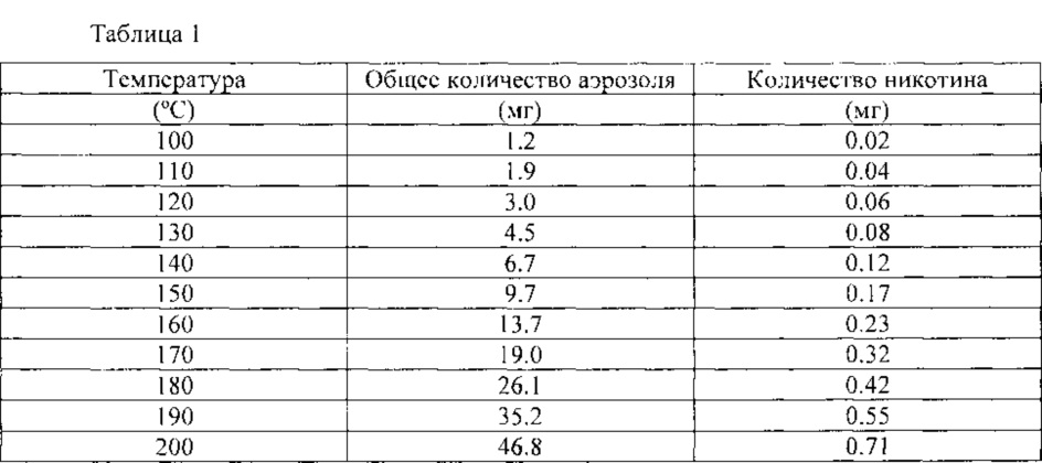
В таблице 1 приведены данные о количестве генерируемого описываемой здесь картомайзерной системой аэрозоля при объеме затяжки 55 мл (причем 45% объема затяжки проходит по каналу 190 для потока воздуха) с использованием раствора ароматизатора, содержащего 4% никотина в смеси 40% глицерина и 60% пропиленгликоля. Отметим, что этот расчет предполагает 100% насыщение паров, что является верхним пределом передачи материала.Table 1 shows the amount of aerosol generated by the cartomizer aerosol system described here with a puff volume of 55 ml (with 45% of the puff volume passing through
Приведенные здесь положения применимы к электронным сигарам, а ссылка на «электронное курительное изделия (я)» должна включать также электронные сигары, электронные сигареты и другие подобные объекты.The provisions here apply to electronic cigars, and the reference to “electronic smoking article (s)” should also include electronic cigars, electronic cigarettes and other similar objects.
Когда слово «примерно» используется в настоящем описании в сочетании с числовой величиной, оно должно означать, что значение ассоциированной числовой величины лежит в пределах поля допуска ±10% от указанного значения. Более того, когда в описании есть ссылка на процентную долю, речь идет о процентах по массе, т.е. массовых процентах.When the word “about” is used in the present description in combination with a numerical value, it should mean that the value of the associated numerical value lies within the tolerance range of ± 10% of the specified value. Moreover, when the description refers to a percentage, we are talking about percent by weight, i.e. mass percent.
Кроме того, когда слова «в общем случае» и «по существу» используются в связи с указанием геометрической формы, это означает, что здесь не требуется точного соответствия указанной форме, так что в объем изобретения попадает некий диапазон форм, аппроксимирующих указанную форму. Когда слова «в общем случае» и «по существу» используются с геометрическими терминами, они охватывают не только признаки, отвечающие строгим определениям, но и признаки, в достаточной степени приблизительно соответствующие таким строгим определениям.In addition, when the words “in the general case” and “essentially” are used in connection with an indication of the geometric shape, this means that it does not require exact correspondence to the specified shape, so that a certain range of shapes approximating the specified shape falls within the scope of the invention. When the words “in the general case” and “in essence” are used with geometric terms, they encompass not only features that meet strict definitions, but also features that sufficiently adequately correspond to such strict definitions.
Теперь легко видеть, что новая усовершенствованная и неочевидная электронная сигарета охарактеризована в настоящем описании достаточно подробно для понимания даже рядовым специалистом в рассматриваемой области. Кроме того, для специалистов должно быть очевидно, что возможны многочисленные модификации, изменения, замены и эквиваленты для признаков электронной сигареты, не отклоняющиеся значительно от существа и объема изобретения. Таким образом, четко указано, что все такие модификации, изменения, замены и эквиваленты, находящиеся в пределах существа и объема изобретения согласно прилагаемой формуле изобретения, охвачены прилагаемой формулой.Now it is easy to see that the new improved and non-obvious electronic cigarette is described in the present description in sufficient detail for understanding even by an ordinary person skilled in the art. In addition, it should be apparent to those skilled in the art that numerous modifications, changes, replacements, and equivalents are possible for the features of an electronic cigarette, not deviating significantly from the spirit and scope of the invention. Thus, it is clearly indicated that all such modifications, changes, substitutions and equivalents that are within the essence and scope of the invention according to the attached claims are covered by the attached claims.
Claims (23)
Applications Claiming Priority (4)
| Application Number | Priority Date | Filing Date | Title |
|---|---|---|---|
| US201361799499P | 2013-03-15 | 2013-03-15 | |
| US61/799,499 | 2013-03-15 | ||
| US61/779,499 | 2013-03-15 | ||
| PCT/US2014/022648 WO2014150229A1 (en) | 2013-03-15 | 2014-03-10 | Electronic cigarette |
Publications (2)
| Publication Number | Publication Date |
|---|---|
| RU2015144290A RU2015144290A (en) | 2017-04-24 |
| RU2646737C2 true RU2646737C2 (en) | 2018-03-06 |
Family
ID=50442654
Family Applications (1)
| Application Number | Title | Priority Date | Filing Date |
|---|---|---|---|
| RU2015144290A RU2646737C2 (en) | 2013-03-15 | 2014-03-10 | Electronic cigarette |
Country Status (12)
| Country | Link |
|---|---|
| US (3) | US9877508B2 (en) |
| EP (1) | EP2967146B1 (en) |
| KR (1) | KR20160012109A (en) |
| CN (1) | CN105307519B (en) |
| AR (1) | AR095670A1 (en) |
| CA (1) | CA2904953A1 (en) |
| ES (1) | ES2681951T3 (en) |
| MA (1) | MA38387B1 (en) |
| PL (1) | PL2967146T3 (en) |
| RU (1) | RU2646737C2 (en) |
| UA (1) | UA116133C2 (en) |
| WO (1) | WO2014150229A1 (en) |
Cited By (2)
| Publication number | Priority date | Publication date | Assignee | Title |
|---|---|---|---|---|
| RU2764272C1 (en) * | 2018-06-29 | 2022-01-17 | Никовенчерс Трейдинг Лимитед | Vapour supply apparatus |
| RU2777385C1 (en) * | 2019-04-25 | 2022-08-02 | Филип Моррис Продактс С.А. | Aerosol-generating apparatus and aerosol generation system |
Families Citing this family (89)
| Publication number | Priority date | Publication date | Assignee | Title |
|---|---|---|---|---|
| US10244793B2 (en) | 2005-07-19 | 2019-04-02 | Juul Labs, Inc. | Devices for vaporization of a substance |
| AT507187B1 (en) | 2008-10-23 | 2010-03-15 | Helmut Dr Buchberger | INHALER |
| AT510837B1 (en) | 2011-07-27 | 2012-07-15 | Helmut Dr Buchberger | INHALATORKOMPONENTE |
| JP5681819B2 (en) | 2011-02-11 | 2015-03-11 | バットマーク・リミテッド | Inhaler components |
| KR102433286B1 (en) | 2011-09-06 | 2022-08-16 | 니코벤처스 트레이딩 리미티드 | Heating smokable material |
| KR102309513B1 (en) | 2011-09-06 | 2021-10-05 | 니코벤처스 트레이딩 리미티드 | Heating smokeable material |
| AT511344B1 (en) | 2011-10-21 | 2012-11-15 | Helmut Dr Buchberger | INHALATORKOMPONENTE |
| GB201207039D0 (en) | 2012-04-23 | 2012-06-06 | British American Tobacco Co | Heating smokeable material |
| GB2504076A (en) | 2012-07-16 | 2014-01-22 | Nicoventures Holdings Ltd | Electronic smoking device |
| US10279934B2 (en) | 2013-03-15 | 2019-05-07 | Juul Labs, Inc. | Fillable vaporizer cartridge and method of filling |
| GB2513639A (en) * | 2013-05-02 | 2014-11-05 | Nicoventures Holdings Ltd | Electronic cigarette |
| GB2513637A (en) * | 2013-05-02 | 2014-11-05 | Nicoventures Holdings Ltd | Electronic cigarette |
| GB2513638A (en) | 2013-05-02 | 2014-11-05 | Nicoventures Holdings Ltd | Electronic cigarette |
| GB2514893B (en) | 2013-06-04 | 2017-12-06 | Nicoventures Holdings Ltd | Container |
| WO2014195688A1 (en) | 2013-06-04 | 2014-12-11 | Nicoventures Holdings Limited | Container |
| US10980273B2 (en) | 2013-11-12 | 2021-04-20 | VMR Products, LLC | Vaporizer, charger and methods of use |
| US10039321B2 (en) * | 2013-11-12 | 2018-08-07 | Vmr Products Llc | Vaporizer |
| US10076139B2 (en) | 2013-12-23 | 2018-09-18 | Juul Labs, Inc. | Vaporizer apparatus |
| US10058129B2 (en) | 2013-12-23 | 2018-08-28 | Juul Labs, Inc. | Vaporization device systems and methods |
| USD825102S1 (en) | 2016-07-28 | 2018-08-07 | Juul Labs, Inc. | Vaporizer device with cartridge |
| US10159282B2 (en) | 2013-12-23 | 2018-12-25 | Juul Labs, Inc. | Cartridge for use with a vaporizer device |
| US20160366947A1 (en) | 2013-12-23 | 2016-12-22 | James Monsees | Vaporizer apparatus |
| JP6653432B2 (en) | 2013-12-23 | 2020-02-26 | ジュール・ラブズ・インコーポレイテッドJuul Labs, Inc. | Vaporizer system and method |
| USD842536S1 (en) | 2016-07-28 | 2019-03-05 | Juul Labs, Inc. | Vaporizer cartridge |
| US10709173B2 (en) | 2014-02-06 | 2020-07-14 | Juul Labs, Inc. | Vaporizer apparatus |
| GB201407426D0 (en) | 2014-04-28 | 2014-06-11 | Batmark Ltd | Aerosol forming component |
| US9872520B1 (en) * | 2014-06-26 | 2018-01-23 | Jeffrey Alan Elson | Vaporizer with means to power and recharge electrical devices |
| GB2528673B (en) | 2014-07-25 | 2020-07-01 | Nicoventures Holdings Ltd | Aerosol provision system |
| WO2016029475A1 (en) * | 2014-08-29 | 2016-03-03 | 深圳麦克韦尔股份有限公司 | Electronic cigarette and assembly method therefor |
| GB2530980A (en) * | 2014-09-19 | 2016-04-13 | Kind Consumer Ltd | Simulated cigarette |
| ES2964622T3 (en) * | 2014-09-30 | 2024-04-08 | Philip Morris Products Sa | Recovery of tobacco constituents from processing |
| MX2017007042A (en) | 2014-12-05 | 2018-06-15 | Juul Labs Inc | Calibrated dose control. |
| GB2533135B (en) | 2014-12-11 | 2020-11-11 | Nicoventures Holdings Ltd | Aerosol provision systems |
| GB201501429D0 (en) * | 2015-01-28 | 2015-03-11 | British American Tobacco Co | Apparatus for heating aerosol generating material |
| WO2016145663A1 (en) * | 2015-03-19 | 2016-09-22 | 惠州市吉瑞科技有限公司 | Atomizing component and electronic cigarette |
| CN104839893B (en) * | 2015-04-28 | 2018-06-26 | 深圳麦克韦尔股份有限公司 | Inhalator and its atomizing component |
| US10772353B2 (en) | 2015-04-28 | 2020-09-15 | Shenzhen Smoore Technology Limited | Inhaler and atomization component thereof |
| CN208425507U (en) * | 2015-04-30 | 2019-01-25 | 惠州市吉瑞科技有限公司深圳分公司 | A kind of atomizing component and electronic cigarette |
| CN111990700A (en) | 2015-05-06 | 2020-11-27 | 奥驰亚客户服务有限责任公司 | Non-combustion smoking device and components thereof |
| US20160345621A1 (en) * | 2015-06-01 | 2016-12-01 | San Li | Pre-vapor formulation of an electronic vaping device and/or methods of manufacturing the same |
| CN106307615B (en) * | 2015-06-17 | 2023-10-03 | 深圳市新宜康科技股份有限公司 | Top air inlet electronic cigarette atomizing device |
| GB201511349D0 (en) | 2015-06-29 | 2015-08-12 | Nicoventures Holdings Ltd | Electronic aerosol provision systems |
| CN108024573A (en) | 2015-07-24 | 2018-05-11 | 富特姆控股第有限公司 | The liquid container of electrical smoking device |
| US20170055584A1 (en) | 2015-08-31 | 2017-03-02 | British American Tobacco (Investments) Limited | Article for use with apparatus for heating smokable material |
| US11924930B2 (en) | 2015-08-31 | 2024-03-05 | Nicoventures Trading Limited | Article for use with apparatus for heating smokable material |
| CO2018009342A2 (en) | 2016-02-11 | 2018-09-20 | Juul Labs Inc | Secure fixing cartridges for vaporizing devices |
| SG11201806793TA (en) | 2016-02-11 | 2018-09-27 | Juul Labs Inc | Fillable vaporizer cartridge and method of filling |
| US10455863B2 (en) * | 2016-03-03 | 2019-10-29 | Altria Client Services Llc | Cartridge for electronic vaping device |
| US10405582B2 (en) | 2016-03-10 | 2019-09-10 | Pax Labs, Inc. | Vaporization device with lip sensing |
| US10264821B2 (en) | 2016-03-21 | 2019-04-23 | Altria Client Services Llc | Electronic vaping device |
| MY192211A (en) | 2016-04-27 | 2022-08-08 | Nicoventures Trading Ltd | Electronic aerosol provision system and vaporizer therefor |
| USD849996S1 (en) | 2016-06-16 | 2019-05-28 | Pax Labs, Inc. | Vaporizer cartridge |
| USD851830S1 (en) | 2016-06-23 | 2019-06-18 | Pax Labs, Inc. | Combined vaporizer tamp and pick tool |
| USD836541S1 (en) | 2016-06-23 | 2018-12-25 | Pax Labs, Inc. | Charging device |
| USD848057S1 (en) | 2016-06-23 | 2019-05-07 | Pax Labs, Inc. | Lid for a vaporizer |
| US10602775B2 (en) * | 2016-07-21 | 2020-03-31 | Rai Strategic Holdings, Inc. | Aerosol delivery device with a unitary reservoir and liquid transport element comprising a porous monolith and related method |
| US10842193B2 (en) | 2016-10-04 | 2020-11-24 | Altria Client Services Llc | Non-combustible smoking device and elements thereof |
| US10433585B2 (en) | 2016-12-28 | 2019-10-08 | Altria Client Services Llc | Non-combustible smoking systems, devices and elements thereof |
| CN110612032A (en) * | 2017-05-05 | 2019-12-24 | 惠州市吉瑞科技有限公司深圳分公司 | Electronic cigarette control method and electronic cigarette |
| CN107280073B (en) * | 2017-07-10 | 2023-08-15 | 云南中烟工业有限责任公司 | Suction device with adsorption element |
| US10603459B2 (en) | 2017-07-20 | 2020-03-31 | Eric Kotch | Variable viscosity vaporizer cartridge |
| USD887632S1 (en) | 2017-09-14 | 2020-06-16 | Pax Labs, Inc. | Vaporizer cartridge |
| US20200035118A1 (en) | 2018-07-27 | 2020-01-30 | Joseph Pandolfino | Methods and products to facilitate smokers switching to a tobacco heating product or e-cigarettes |
| US10897925B2 (en) | 2018-07-27 | 2021-01-26 | Joseph Pandolfino | Articles and formulations for smoking products and vaporizers |
| GB201815467D0 (en) * | 2018-09-24 | 2018-11-07 | Nerudia Ltd | Aerosol delivery device |
| GB201815468D0 (en) * | 2018-09-24 | 2018-11-07 | Nerudia Ltd | Aerosol delivery device |
| US10939702B2 (en) | 2018-10-12 | 2021-03-09 | Rai Strategic Holdings, Inc. | Connectors for forming electrical and mechanical connections between interchangeable units in an aerosol delivery system |
| US10791767B2 (en) | 2018-10-12 | 2020-10-06 | Rai Strategic Holdings, Inc. | Connectors for forming electrical and mechanical connections between interchangeable units in an aerosol delivery system |
| US11291249B2 (en) | 2018-10-12 | 2022-04-05 | Rai Strategic Holdings, Inc. | Aerosol delivery device with visible indicator |
| US11588287B2 (en) | 2018-10-12 | 2023-02-21 | Rai Strategic Holdings, Inc. | Aerosol delivery device with improved connectivity, airflow, and aerosol paths |
| US11678700B2 (en) | 2018-10-12 | 2023-06-20 | Rai Strategic Holdings, Inc. | Aerosol delivery device with visible indicator |
| US11974603B2 (en) | 2018-10-12 | 2024-05-07 | Rai Strategic Holdings, Inc. | Aerosol delivery device with visible indicator |
| US11614720B2 (en) | 2018-11-19 | 2023-03-28 | Rai Strategic Holdings, Inc. | Temperature control in an aerosol delivery device |
| US11372153B2 (en) | 2018-11-19 | 2022-06-28 | Rai Strategic Holdings, Inc. | Cartridge orientation for selection of a control function in a vaporization system |
| US11592793B2 (en) | 2018-11-19 | 2023-02-28 | Rai Strategic Holdings, Inc. | Power control for an aerosol delivery device |
| US11156766B2 (en) | 2018-11-19 | 2021-10-26 | Rai Strategic Holdings, Inc. | Aerosol delivery device |
| US11154086B2 (en) | 2019-01-21 | 2021-10-26 | Altria Client Services Llc | Capsules, heat-not-burn (HNB) aerosol-generating devices, and methods of generating an aerosol |
| US11517684B2 (en) * | 2019-01-21 | 2022-12-06 | Altria Client Services Llc | Capsules, heat-not-burn (HNB) aerosol-generating devices, and methods of generating an aerosol |
| EP3692830A1 (en) * | 2019-02-07 | 2020-08-12 | Nerudia Limited | Smoking substitute device |
| CN109730365B (en) * | 2019-03-04 | 2020-11-03 | 云南巴菰生物科技有限公司 | Negative pressure anaerobic smoking heating non-combustible cigarette |
| GB201903537D0 (en) * | 2019-03-15 | 2019-05-01 | Nicoventures Trading Ltd | Flow directing member for a vapour provision system |
| KR102353865B1 (en) * | 2019-08-08 | 2022-01-20 | 주식회사 케이티앤지 | Aerosol generating system |
| JP2022547407A (en) * | 2019-08-30 | 2022-11-14 | ジェイティー インターナショナル エス.エイ. | e-cigarette cartridge |
| RU2717907C1 (en) * | 2019-09-16 | 2020-03-26 | Федеральное государственное унитарное предприятие "Центральный аэрогидродинамический институт имени профессора Н.Е. Жуковского" (ФГУП "ЦАГИ") | Smoke generator |
| CN112369726B (en) * | 2019-11-28 | 2023-09-08 | 湖北中烟工业有限责任公司 | Heating device for low-temperature cigarettes |
| CN111109672A (en) * | 2020-01-14 | 2020-05-08 | 云南中烟工业有限责任公司 | Liquefiable solid aerosol matrix smoking set and using method thereof |
| US11856986B2 (en) | 2020-10-19 | 2024-01-02 | Rai Strategic Holdings, Inc. | Customizable panel for aerosol delivery device |
| CN113261706A (en) * | 2021-06-02 | 2021-08-17 | 佛山天为环保科技有限公司 | Electronic atomizer |
| KR20230103462A (en) * | 2021-12-31 | 2023-07-07 | 주식회사 케이티앤지 | Aerosol generating device |
Citations (3)
| Publication number | Priority date | Publication date | Assignee | Title |
|---|---|---|---|---|
| US4846199A (en) * | 1986-03-17 | 1989-07-11 | The Regents Of The University Of California | Smoking of regenerated tobacco smoke |
| US4969476A (en) * | 1986-09-19 | 1990-11-13 | Imperial Tobacco Limited | Smoking article |
| US20130037041A1 (en) * | 2011-08-09 | 2013-02-14 | R. J. Reynolds Tobacco Company | Smoking articles and use thereof for yielding inhalation materials |
Family Cites Families (21)
| Publication number | Priority date | Publication date | Assignee | Title |
|---|---|---|---|---|
| US4574181A (en) * | 1984-10-09 | 1986-03-04 | Donald Spector | Aroma-generating automobile cigarette lighter |
| US5665262A (en) * | 1991-03-11 | 1997-09-09 | Philip Morris Incorporated | Tubular heater for use in an electrical smoking article |
| US5666977A (en) | 1993-06-10 | 1997-09-16 | Philip Morris Incorporated | Electrical smoking article using liquid tobacco flavor medium delivery system |
| US5743251A (en) | 1996-05-15 | 1998-04-28 | Philip Morris Incorporated | Aerosol and a method and apparatus for generating an aerosol |
| ATE341952T1 (en) | 2001-12-19 | 2006-11-15 | Vector Tobacco Ltd | METHOD AND COMPOSITION FOR MENTHOL ENCOURAGEMENT OF CIGARETTES |
| CN2719043Y (en) | 2004-04-14 | 2005-08-24 | 韩力 | Atomized electronic cigarette |
| WO2007078273A1 (en) | 2005-12-22 | 2007-07-12 | Augite Incorporation | No-tar electronic smoking utensils |
| FR2895644B1 (en) * | 2006-01-03 | 2008-05-16 | Didier Gerard Martzel | SUBSTITUTE OF CIGARETTE |
| US7726320B2 (en) | 2006-10-18 | 2010-06-01 | R. J. Reynolds Tobacco Company | Tobacco-containing smoking article |
| US7845359B2 (en) * | 2007-03-22 | 2010-12-07 | Pierre Denain | Artificial smoke cigarette |
| US9155848B2 (en) * | 2007-10-15 | 2015-10-13 | Vapir, Inc. | Method and system for vaporization of a substance |
| EP2113178A1 (en) | 2008-04-30 | 2009-11-04 | Philip Morris Products S.A. | An electrically heated smoking system having a liquid storage portion |
| GB0813686D0 (en) * | 2008-07-25 | 2008-09-03 | Gamucci Ltd | A method and apparatus relating to electronic smoking-substitute devices |
| CN201379072Y (en) * | 2009-02-11 | 2010-01-13 | 韩力 | Improved atomizing electronic cigarette |
| CN101606758B (en) * | 2009-07-14 | 2011-04-13 | 方晓林 | Electronic cigarette |
| US8550068B2 (en) * | 2010-05-15 | 2013-10-08 | Nathan Andrew Terry | Atomizer-vaporizer for a personal vaporizing inhaler |
| EP2641490A4 (en) | 2010-11-19 | 2017-06-21 | Kimree Hi-Tech Inc | Electronic cigarette, electronic cigarette flare and atomizer thereof |
| UA112883C2 (en) * | 2011-12-08 | 2016-11-10 | Філіп Морріс Продактс С.А. | DEVICE FOR THE FORMATION OF AEROSOL WITH A CAPILLARY BORDER LAYER |
| DE202013100606U1 (en) | 2013-02-11 | 2013-02-27 | Ewwk Ug | Electronic cigarette or pipe |
| US10264819B2 (en) * | 2013-03-15 | 2019-04-23 | Altria Client Services Llc | Electronic smoking article |
| CN103960782B (en) * | 2013-09-29 | 2016-09-21 | 深圳麦克韦尔股份有限公司 | Electronic cigarette |
-
2014
- 2014-03-06 US US14/199,555 patent/US9877508B2/en active Active
- 2014-03-10 KR KR1020157029876A patent/KR20160012109A/en not_active Application Discontinuation
- 2014-03-10 CA CA2904953A patent/CA2904953A1/en not_active Abandoned
- 2014-03-10 EP EP14716109.5A patent/EP2967146B1/en not_active Not-in-force
- 2014-03-10 MA MA38387A patent/MA38387B1/en unknown
- 2014-03-10 ES ES14716109.5T patent/ES2681951T3/en active Active
- 2014-03-10 PL PL14716109T patent/PL2967146T3/en unknown
- 2014-03-10 RU RU2015144290A patent/RU2646737C2/en not_active IP Right Cessation
- 2014-03-10 CN CN201480016003.2A patent/CN105307519B/en not_active Expired - Fee Related
- 2014-03-10 WO PCT/US2014/022648 patent/WO2014150229A1/en active Application Filing
- 2014-03-18 AR ARP140101277A patent/AR095670A1/en unknown
- 2014-10-03 UA UAA201510025A patent/UA116133C2/en unknown
-
2017
- 2017-12-27 US US15/855,193 patent/US10159288B2/en active Active
-
2018
- 2018-12-21 US US16/229,801 patent/US10667563B2/en active Active
Patent Citations (3)
| Publication number | Priority date | Publication date | Assignee | Title |
|---|---|---|---|---|
| US4846199A (en) * | 1986-03-17 | 1989-07-11 | The Regents Of The University Of California | Smoking of regenerated tobacco smoke |
| US4969476A (en) * | 1986-09-19 | 1990-11-13 | Imperial Tobacco Limited | Smoking article |
| US20130037041A1 (en) * | 2011-08-09 | 2013-02-14 | R. J. Reynolds Tobacco Company | Smoking articles and use thereof for yielding inhalation materials |
Cited By (3)
| Publication number | Priority date | Publication date | Assignee | Title |
|---|---|---|---|---|
| RU2790191C2 (en) * | 2018-06-25 | 2023-02-15 | Джуул Лэбз, Инк. | Evaporating device and its functioning method |
| RU2764272C1 (en) * | 2018-06-29 | 2022-01-17 | Никовенчерс Трейдинг Лимитед | Vapour supply apparatus |
| RU2777385C1 (en) * | 2019-04-25 | 2022-08-02 | Филип Моррис Продактс С.А. | Aerosol-generating apparatus and aerosol generation system |
Also Published As
| Publication number | Publication date |
|---|---|
| UA116133C2 (en) | 2018-02-12 |
| KR20160012109A (en) | 2016-02-02 |
| PL2967146T3 (en) | 2018-10-31 |
| MA38387B1 (en) | 2016-09-30 |
| AR095670A1 (en) | 2015-11-04 |
| ES2681951T3 (en) | 2018-09-17 |
| RU2015144290A (en) | 2017-04-24 |
| US10159288B2 (en) | 2018-12-25 |
| CA2904953A1 (en) | 2014-09-25 |
| US20180116293A1 (en) | 2018-05-03 |
| EP2967146A1 (en) | 2016-01-20 |
| US20190133193A1 (en) | 2019-05-09 |
| CN105307519B (en) | 2018-03-13 |
| EP2967146B1 (en) | 2018-05-09 |
| US10667563B2 (en) | 2020-06-02 |
| US20140261490A1 (en) | 2014-09-18 |
| WO2014150229A1 (en) | 2014-09-25 |
| MA38387A1 (en) | 2016-02-29 |
| CN105307519A (en) | 2016-02-03 |
| US9877508B2 (en) | 2018-01-30 |
Similar Documents
| Publication | Publication Date | Title |
|---|---|---|
| RU2646737C2 (en) | Electronic cigarette | |
| RU2701846C2 (en) | Aerosol-forming system using venturi effect for delivering substrate to heating element | |
| RU2760356C2 (en) | Aerosol generating system that contains cartridge containing gel and device for heating cartridge | |
| RU2645451C2 (en) | Electronic smoking article | |
| RU2736842C2 (en) | Aerosol-generating system comprising a cartridge containing a gel | |
| RU2745143C2 (en) | Refillable aerosol generating product | |
| RU2646554C2 (en) | Electrically heaved cooking system, having a land for storage of a liquid | |
| RU2611489C2 (en) | Electronic smoking article | |
| RU2730164C2 (en) | Aerosol generating device having a side cavity | |
| RU2657683C2 (en) | Electronic smoking article | |
| RU2662212C2 (en) | Electronic smoking article | |
| CN109219360B (en) | Aerosol-generating system comprising a heated aerosol-generating article | |
| CN110507008B (en) | Aerosol delivery device, fragrance delivery device, and method of generating a scented aerosol | |
| RU2661840C2 (en) | Aerosol-generating system with replaceable mouthpiece cap | |
| RU2661461C2 (en) | Electronic smoking article | |
| US10512285B2 (en) | Method of controlling aerosol production to control aerosol properties | |
| RU2709770C2 (en) | Electric aerosol-generating device, cartridge and aerosol-generating system | |
| EA031314B1 (en) | Electronic vaping article with controlled resistance-to-draw in an air flow path | |
| KR20130139298A (en) | An aerosol generating system with leakage prevention | |
| CN113286527A (en) | Nebulizer and aerosol-generating system comprising a nebulizer | |
| RU111765U1 (en) | PERSONAL INHALATOR | |
| RU2805451C2 (en) | Nebulizer for electrically heated aerosol generating system, electrically heated aerosol generating system (embodiments) and cartridge for aerosol generating system | |
| RU2793873C2 (en) | Cartridge for aerosol generating system containing alkaloid source containing alkaloid-based liquid composition | |
| WO2023104720A1 (en) | Hybrid aerosol-generating system with modular consumable |
Legal Events
| Date | Code | Title | Description |
|---|---|---|---|
| MM4A | The patent is invalid due to non-payment of fees |
Effective date: 20200311 |