RU2644573C2 - Electromechanical generator and method for coversion of mechanical vibrational energy to electric energy - Google Patents
Electromechanical generator and method for coversion of mechanical vibrational energy to electric energy Download PDFInfo
- Publication number
- RU2644573C2 RU2644573C2 RU2015122896A RU2015122896A RU2644573C2 RU 2644573 C2 RU2644573 C2 RU 2644573C2 RU 2015122896 A RU2015122896 A RU 2015122896A RU 2015122896 A RU2015122896 A RU 2015122896A RU 2644573 C2 RU2644573 C2 RU 2644573C2
- Authority
- RU
- Russia
- Prior art keywords
- mass
- electromechanical generator
- elastic
- generator according
- biasing
- Prior art date
Links
- 238000000034 method Methods 0.000 title claims description 7
- 230000010355 oscillation Effects 0.000 claims abstract description 52
- 230000005611 electricity Effects 0.000 claims abstract description 4
- 239000007787 solid Substances 0.000 claims description 18
- 230000035939 shock Effects 0.000 claims description 11
- 239000000463 material Substances 0.000 claims description 10
- 230000008859 change Effects 0.000 claims description 8
- 238000005266 casting Methods 0.000 claims description 5
- 230000000694 effects Effects 0.000 abstract description 2
- 238000007789 sealing Methods 0.000 abstract 1
- 239000000126 substance Substances 0.000 abstract 1
- 230000004048 modification Effects 0.000 description 13
- 238000012986 modification Methods 0.000 description 13
- 230000001133 acceleration Effects 0.000 description 6
- 238000006243 chemical reaction Methods 0.000 description 4
- 230000004907 flux Effects 0.000 description 3
- 239000002184 metal Substances 0.000 description 2
- 229910000906 Bronze Inorganic materials 0.000 description 1
- 208000031968 Cadaver Diseases 0.000 description 1
- OAICVXFJPJFONN-UHFFFAOYSA-N Phosphorus Chemical compound [P] OAICVXFJPJFONN-UHFFFAOYSA-N 0.000 description 1
- 229910000639 Spring steel Inorganic materials 0.000 description 1
- 229910000831 Steel Inorganic materials 0.000 description 1
- 230000008901 benefit Effects 0.000 description 1
- 239000010974 bronze Substances 0.000 description 1
- KUNSUQLRTQLHQQ-UHFFFAOYSA-N copper tin Chemical compound [Cu].[Sn] KUNSUQLRTQLHQQ-UHFFFAOYSA-N 0.000 description 1
- 238000013016 damping Methods 0.000 description 1
- 230000006866 deterioration Effects 0.000 description 1
- 239000013013 elastic material Substances 0.000 description 1
- 230000005674 electromagnetic induction Effects 0.000 description 1
- 238000005516 engineering process Methods 0.000 description 1
- 230000007717 exclusion Effects 0.000 description 1
- 238000000605 extraction Methods 0.000 description 1
- 230000002349 favourable effect Effects 0.000 description 1
- 230000005484 gravity Effects 0.000 description 1
- 230000001788 irregular Effects 0.000 description 1
- 230000007246 mechanism Effects 0.000 description 1
- 230000002035 prolonged effect Effects 0.000 description 1
- 231100000812 repeated exposure Toxicity 0.000 description 1
- 239000011343 solid material Substances 0.000 description 1
- 239000010959 steel Substances 0.000 description 1
Images
Classifications
-
- H—ELECTRICITY
- H02—GENERATION; CONVERSION OR DISTRIBUTION OF ELECTRIC POWER
- H02N—ELECTRIC MACHINES NOT OTHERWISE PROVIDED FOR
- H02N2/00—Electric machines in general using piezoelectric effect, electrostriction or magnetostriction
- H02N2/18—Electric machines in general using piezoelectric effect, electrostriction or magnetostriction producing electrical output from mechanical input, e.g. generators
- H02N2/186—Vibration harvesters
- H02N2/188—Vibration harvesters adapted for resonant operation
-
- H—ELECTRICITY
- H02—GENERATION; CONVERSION OR DISTRIBUTION OF ELECTRIC POWER
- H02K—DYNAMO-ELECTRIC MACHINES
- H02K35/00—Generators with reciprocating, oscillating or vibrating coil system, magnet, armature or other part of the magnetic circuit
-
- F—MECHANICAL ENGINEERING; LIGHTING; HEATING; WEAPONS; BLASTING
- F16—ENGINEERING ELEMENTS AND UNITS; GENERAL MEASURES FOR PRODUCING AND MAINTAINING EFFECTIVE FUNCTIONING OF MACHINES OR INSTALLATIONS; THERMAL INSULATION IN GENERAL
- F16F—SPRINGS; SHOCK-ABSORBERS; MEANS FOR DAMPING VIBRATION
- F16F15/00—Suppression of vibrations in systems; Means or arrangements for avoiding or reducing out-of-balance forces, e.g. due to motion
- F16F15/02—Suppression of vibrations of non-rotating, e.g. reciprocating systems; Suppression of vibrations of rotating systems by use of members not moving with the rotating systems
- F16F15/03—Suppression of vibrations of non-rotating, e.g. reciprocating systems; Suppression of vibrations of rotating systems by use of members not moving with the rotating systems using magnetic or electromagnetic means
-
- H—ELECTRICITY
- H02—GENERATION; CONVERSION OR DISTRIBUTION OF ELECTRIC POWER
- H02K—DYNAMO-ELECTRIC MACHINES
- H02K35/00—Generators with reciprocating, oscillating or vibrating coil system, magnet, armature or other part of the magnetic circuit
- H02K35/06—Generators with reciprocating, oscillating or vibrating coil system, magnet, armature or other part of the magnetic circuit with moving flux distributors, and both coil systems and magnets stationary
-
- H—ELECTRICITY
- H02—GENERATION; CONVERSION OR DISTRIBUTION OF ELECTRIC POWER
- H02K—DYNAMO-ELECTRIC MACHINES
- H02K7/00—Arrangements for handling mechanical energy structurally associated with dynamo-electric machines, e.g. structural association with mechanical driving motors or auxiliary dynamo-electric machines
- H02K7/18—Structural association of electric generators with mechanical driving motors, e.g. with turbines
-
- H—ELECTRICITY
- H02—GENERATION; CONVERSION OR DISTRIBUTION OF ELECTRIC POWER
- H02N—ELECTRIC MACHINES NOT OTHERWISE PROVIDED FOR
- H02N2/00—Electric machines in general using piezoelectric effect, electrostriction or magnetostriction
- H02N2/18—Electric machines in general using piezoelectric effect, electrostriction or magnetostriction producing electrical output from mechanical input, e.g. generators
- H02N2/186—Vibration harvesters
Abstract
Description
Настоящее изобретение относится к электромеханическому генератору для преобразования механической вибрационной энергии в электрическую энергию. Кроме того, настоящее изобретение относится к способу преобразования механической вибрационной энергии в электрическую энергию, используя электромеханический генератор. В частности, настоящее изобретение относится к такому устройству, которое является миниатюрным генератором, способным преобразовывать окружающую вибрационную энергию в электрическую энергию для ее использования, например, для питания интеллектуальных сенсорных систем. Такая система может быть использована во многих областях, где исключение силовых кабелей или аккумуляторных батарей представляет собой экономическое или функциональное преимущество. The present invention relates to an electromechanical generator for converting mechanical vibrational energy into electrical energy. In addition, the present invention relates to a method for converting mechanical vibrational energy into electrical energy using an electromechanical generator. In particular, the present invention relates to such a device, which is a miniature generator capable of converting the surrounding vibrational energy into electrical energy for its use, for example, to power smart sensor systems. Such a system can be used in many areas where the exclusion of power cables or batteries is an economic or functional advantage.
Электромеханические генераторы для преобразования механической вибрационной энергии в электрическую энергию в соответствующей области хорошо известны и состоят из механических резонаторов либо с электромагнитной индукцией, либо с преобразованием пьезоэлектрической энергии. В любом случае механический резонатор состоит из подпружиненной массы. Известно использование электромеханического генератора для извлечения полезной электрической энергии из окружающих вибраций, например, с целью питания беспроводных датчиков. Известны также генераторы с другими системами преобразования, такими как магнитострикционные или электростатические системы. Electromechanical generators for converting mechanical vibrational energy into electrical energy in the corresponding field are well known and consist of mechanical resonators with either electromagnetic induction or piezoelectric energy conversion. In any case, the mechanical resonator consists of a spring-loaded mass. It is known to use an electromechanical generator to extract useful electrical energy from surrounding vibrations, for example, to power wireless sensors. Generators with other conversion systems, such as magnetostrictive or electrostatic systems, are also known.
Типичный электромеханический генератор представляет собой генератор на электромагнитной катушке, который состоит из комбинации механической пружинной массы, прикрепленной к магниту или к катушке таким образом, что когда система вибрирует, катушка пересекает поток, созданный магнитным сердечником. Масса, которая при вибрации перемещается, обычно установлена на консольном элементе. Элемент может быть либо подсоединен к магнитному сердечнику с катушкой, фиксированной относительно корпуса устройства, либо наоборот. A typical electromechanical generator is an electromagnetic coil generator, which consists of a combination of a mechanical spring mass attached to a magnet or coil so that when the system vibrates, the coil crosses the flux generated by the magnetic core. The mass that moves during vibration is usually mounted on the cantilever element. The element can either be connected to a magnetic core with a coil fixed relative to the device body, or vice versa.
Во время работы электромеханический генератор может подвергаться большой ударной силе или вибрации, что заставляет подпружиненную массу, совершать колебания с чрезмерно большой амплитудой, в результате чего эта масса в конце своего перемещения может физически ударяться о внешний корпус устройства или о другие компоненты. Хотя теоретически эту массу можно отнести подальше от корпуса или других компонентов, чтобы обеспечить такие большие амплитуды колебаний без соударений, это делает общее устройство более объемным, что ограничивает его применение в меньших пространствах, наверняка увеличивает его вес и требует использования большего количества материала для формирования его корпуса. Если никакого корпуса нет, или если масса во избежание ударов удалена подальше от корпуса и других компонентов, тогда масса может осциллировать с исключительно большой амплитудой, что вызывает неустраняемое повреждение или постепенное ухудшение пружины в результате многократного превышения пределов пропорциональности материала пружины. В любом случае можно ожидать, что эти соударения или колебания с исключительно большой амплитудой сократят срок службы электромеханического генератора до неприемлемой степени. During operation, the electromechanical generator can be subjected to a large shock force or vibration, which causes the spring mass to oscillate with an excessively large amplitude, as a result of which this mass at the end of its movement can physically hit the external case of the device or other components. Although theoretically this mass can be taken away from the case or other components to provide such large amplitudes of vibrations without collisions, this makes the overall device more voluminous, which limits its use in smaller spaces, certainly increases its weight and requires the use of more material to form it corps. If there is no housing, or if the mass is removed away from the housing and other components in order to avoid impacts, then the mass can oscillate with an extremely large amplitude, which causes permanent damage or gradual deterioration of the spring as a result of repeatedly exceeding the proportional limits of the spring material. In any case, it can be expected that these collisions or oscillations with an extremely large amplitude will reduce the life of the electromechanical generator to an unacceptable degree.
Устройства извлечения энергии резонансной вибрации создаются преимущественно таким образом, чтобы их добротность была как можно более высокой. Это так, потому что на резонаторах с большей добротностью могут генерироваться более высокие энергии. Однако если такое устройство оказалось в таком окружении, где возбуждающая вибрация становится по амплитуде больше, чем ожидалось, или такое устройство подвергается воздействию высоких нерегулярных ударных сил, то амплитуда колебаний резонатора может стать больше, чем та, для которой он был предназначен или на которую был настроен. Эта амплитуда колебаний может заставить резонирующую массу ударяться о корпус устройства или другие компоненты и после продолжительного воздействия потенциально приводит к неустраняемому повреждению. Resonant vibration energy extraction devices are created primarily in such a way that their quality factor is as high as possible. This is so because higher energies can be generated on resonators with higher quality factors. However, if such a device is in an environment where the exciting vibration becomes larger in amplitude than expected, or such a device is exposed to high irregular impact forces, then the amplitude of the resonator oscillations may become larger than the one for which it was designed or for which configured. This vibration amplitude can cause the resonant mass to hit the device body or other components and, after prolonged exposure, can potentially cause permanent damage.
Соответственно, есть потребность в создании электромеханического генератора, который содержал бы в себе возможность изменять во времени амплитуду вибрации или колебаний подпружиненной массы, прерывным и непредсказуемым образом, и, соответственно, мог бы иметь пониженную возможность повреждения от опасных амплитуд и, тем самым, - повышенный срок службы. Accordingly, there is a need to create an electromechanical generator that would contain the ability to change in time the amplitude of the vibrations or vibrations of the spring loaded mass, in a discontinuous and unpredictable manner, and, accordingly, could have a reduced possibility of damage from dangerous amplitudes and, therefore, increased life time.
Настоящее изобретение направлено на обеспечение усовершенствованного электромеханического генератора для преобразования механической вибрационной энергии в электрическую энергию, который отвечал бы этой потребности. The present invention aims to provide an improved electromechanical generator for converting mechanical vibrational energy into electrical energy that would meet this need.
Кроме того, настоящее изобретение направлено на обеспечение компактного электромеханического генератора для преобразования механической вибрационной энергии в электрическую энергию. In addition, the present invention is directed to providing a compact electromechanical generator for converting mechanical vibrational energy into electrical energy.
Кроме того, настоящее изобретение направлено на обеспечение усовершенствованного электромеханического генератора для преобразования механической вибрационной энергии в электрическую энергию, который включает в себя ограничитель для амплитуды вибрации или колебаний своей массы, который не вызывает каких-либо потерь энергии в генераторе, когда масса колеблется с амплитудой, не большей, чем конкретная или предопределенная пороговая амплитуда, тем самым исключая или минимизируя какое-либо уменьшение эффективности преобразования энергии электромеханического генератора, когда этот электромеханический генератор работает в конкретном или в предопределенном рабочем диапазоне амплитуд, которые не больше, чем конкретная или предопределенная пороговая амплитуда. In addition, the present invention is directed to providing an improved electromechanical generator for converting mechanical vibrational energy into electrical energy, which includes a limiter for the amplitude of vibration or vibrations of its mass, which does not cause any energy loss in the generator when the mass oscillates with amplitude, no more than a specific or predetermined threshold amplitude, thereby eliminating or minimizing any decrease in the energy conversion efficiency ii electromechanical generator when the electromechanical generator is operating in a specific or predetermined working range of amplitudes which are not more than a specific or predetermined threshold amplitude.
Соответственно, в своем первом аспекте настоящее изобретение обеспечивает электромеханический генератор для преобразования механической вибрационной энергии в электрическую энергию, при этом электромеханический генератор содержит массу, упруго подсоединенную к телу посредством смещающего устройства, и выполненную с возможностью совершать колебания у точки равновесия относительно тела с амплитудой колебаний, преобразователь, выполненный с возможностью преобразования колебаний массы у точки равновесия относительно тела в электрическую энергию, и упругое устройство, расположенное между смещающим устройством и одним из массы и тела, при этом упругое устройство выполнено с возможностью быть деформированным между смещающим устройством и одним из массы и тела, - только тогда, когда амплитуда колебаний превышает предопределенную ненулевую пороговую амплитуду. Accordingly, in its first aspect, the present invention provides an electromechanical generator for converting mechanical vibrational energy into electrical energy, wherein the electromechanical generator comprises a mass elastically connected to the body by means of a biasing device, and configured to oscillate at an equilibrium point relative to the body with an oscillation amplitude, a transducer configured to convert mass oscillations at an equilibrium point relative to the body into an electric energy, and an elastic device located between the biasing device and one of the mass and body, while the elastic device is configured to be deformed between the biasing device and one of the mass and body, only when the amplitude of the oscillations exceeds a predetermined nonzero threshold amplitude.
Здесь под термином "ненулевая" подразумевается, что предопределенная пороговая амплитуда не является нулевой амплитудой. Соответственно, когда масса колеблется с предопределенной пороговой амплитудой, эта масса колеблется, вибрирует или совершает движения у точки равновесия относительно тела.Here, the term "non-zero" means that the predetermined threshold amplitude is not a zero amplitude. Accordingly, when the mass oscillates with a predetermined threshold amplitude, this mass oscillates, vibrates or makes movements at the equilibrium point relative to the body.
Генератор сконфигурирован таким образом, что масса имеет возможность совершать колебания у точки равновесия относительно тела с амплитудой колебаний, не большей, чем предопределенная пороговая амплитуда, без того, чтобы упругое устройство было деформировано, то есть, сжато между смещающим устройством и одним из массы и тела. Как таковое упругое устройство в таких схемах не вызывает каких-либо потерь энергии в генераторе, когда амплитуда колебаний массы не больше, чем конкретная или предопределенная пороговая амплитуда. Однако когда генератор сконфигурирован таким образом, что амплитуда колебаний превышает предопределенную пороговую амплитуду, как тогда, когда он подвергается сильному удару, то в этом случае упругое устройство деформируется, то есть, сжимается между смещающим устройством и одним из массы и тела, и действует как ограничитель, который ограничивает амплитуду колебаний. The generator is configured in such a way that the mass has the ability to oscillate at the equilibrium point relative to the body with an amplitude of oscillation not greater than the predetermined threshold amplitude, without the elastic device being deformed, that is, compressed between the biasing device and one of the mass and body . As such, the elastic device in such schemes does not cause any energy loss in the generator when the amplitude of the mass oscillations is not greater than a specific or predetermined threshold amplitude. However, when the generator is configured in such a way that the amplitude of the oscillations exceeds a predetermined threshold amplitude, as when it is subjected to a strong shock, in this case the elastic device is deformed, that is, compressed between the biasing device and one of the mass and body, and acts as a limiter , which limits the amplitude of the oscillations.
Соответственно, электромеханический генератор, воплощающий настоящее изобретение, обладает особой полезностью в таких окружениях, где он может быть подвергнут сильным случайным ударам. Accordingly, an electromechanical generator embodying the present invention is particularly useful in such environments where it can be subjected to strong random impacts.
Упругое устройство может быть выполнено с возможностью контактирования со смещающим устройством, когда это упругое устройство деформировано между смещающим устройством и одним из массы и тела. Альтернативно, электромеханический генератор содержит твердое или жесткое устройство, такое как пружинное кольцо, выполненное с возможностью изоляции упругого устройства от смещающего устройства, когда это упругое устройство деформировано между смещающим устройством и одним из массы и тела.The elastic device may be configured to contact the biasing device when this elastic device is deformed between the biasing device and one of the mass and body. Alternatively, the electromechanical generator comprises a solid or rigid device, such as a spring ring, configured to isolate the elastic device from the biasing device when the elastic device is deformed between the biasing device and one of the mass and the body.
Упругое устройство может быть установлено на одном из массы и тела. Упругое устройство может быть удалено от смещающего устройства, когда масса находится в точке равновесия. Предпочтительно, одно из массы и тела, на котором установлено упругое устройство, содержит твердую поверхность или посадочное место, с которым контактирует упругое устройство. Эта твердая поверхность или посадочное место может быть обеспечено твердым компонентом, таким как кольцевой или не кольцевой компонент, соответственно, массы или тела.An elastic device can be mounted on one of the mass and body. The elastic device can be removed from the biasing device when the mass is at the equilibrium point. Preferably, one of the mass and the body on which the elastic device is mounted comprises a hard surface or a seat with which the elastic device is in contact. This solid surface or seat may be provided with a solid component, such as an annular or non-annular component, respectively, of mass or body.
Упругое устройство может быть установлено на смещающем устройстве. Упругое устройство, когда масса находится в точке равновесия, может быть удалено от одного из массы и тела.The elastic device may be mounted on the biasing device. The elastic device, when the mass is at the equilibrium point, can be removed from one of the mass and body.
Упругое устройство, предпочтительно, имеет коэффициент упругости, который больше, чем коэффициент упругости смещающего устройства. Однако упругое устройство может иметь коэффициент упругости, который меньше чем или равен коэффициенту упругости смещающего устройства.The elastic device preferably has a coefficient of elasticity that is greater than the coefficient of elasticity of the biasing device. However, the elastic device may have an elastic coefficient that is less than or equal to the elastic coefficient of the biasing device.
Упругое устройство может содержать одно из пружинной шайбы, винтовой пружины и эластомерного устройства или отливки, такой как уплотнительное кольцо. Пружинная шайба может быть выбрана из группы, состоящей из тарельчатой шайбы, криволинейной дисковой пружины, волнистой шайбы и разрезной шайбы. Упругое устройство, предпочтительно, является цельным эластичным устройством.The elastic device may comprise one of a spring washer, a coil spring, and an elastomeric device or casting, such as an o-ring. The spring washer may be selected from the group consisting of a disk washer, a curved disk spring, a corrugated washer and a split washer. The resilient device is preferably an integral elastic device.
Электромеханический генератор может содержать пружинное устройство, расположенное между смещающим устройством и одним из массы и тела, и выполненное с возможностью смещать упругое устройство к одному из смещающего устройства и одному из массы и тела. Упругое устройство, предпочтительно, удерживается у смещающего устройства, массы или тела только пружинным устройством. То есть, упругое устройство, предпочтительно, не прикреплено к чему-нибудь из смещающего устройства, массы или тела или не связано с ними каким-либо иным образом. The electromechanical generator may include a spring device located between the biasing device and one of the mass and body, and configured to bias the elastic device to one of the biasing device and one of the mass and body. The resilient device is preferably held by the spring device only against the biasing device, mass or body. That is, the resilient device is preferably not attached to, or otherwise connected to, any of the biasing device, mass or body.
Во время использования электромеханического генератора масса и упругое устройство подвергаются воздействию ускорения. Пружинное устройство должно быть достаточно жестким, для того чтобы противостоять любым силам инерции первого упругого устройства. То есть, когда упругое устройство установлено на одном из массы и смещающего устройства, предпочтительно, хотя и не совершенно необходимо, удерживать упругое устройство в контакте с одним из массы и смещающего устройства в течение всего времени колебаний массы. Для того чтобы достичь этого, между упругим устройством и одним из массы и смещающего устройства на сборке генератора может быть установлено пружинное устройство в сжатом состоянии (которое при этом прилагает минимальное упругое усилие пружинного устройства), так чтобы, когда масса находится в точке равновесия, это упругое устройство было поджато к одному из смещающего устройства и массы. Однако это пружинное устройство должно быть достаточно эластичным, чтобы обеспечивать, что это упругое устройство будет оставаться в контакте с одним из массы и смещающего устройства, когда это упругое устройство деформируется во время колебаний массы (которое при этом прилагает максимальное упругое усилие пружинного устройства). Коэффициент упругости пружинного устройства может быть промежуточным относительно коэффициентов упругости смещающего устройства и упругого устройства.During use of the electromechanical generator, the mass and the elastic device are subjected to acceleration. The spring device must be stiff enough to withstand any inertia forces of the first elastic device. That is, when the elastic device is mounted on one of the mass and the bias device, it is preferable, although not absolutely necessary, to keep the elastic device in contact with one of the mass and the bias device during the entire time of the mass oscillations. In order to achieve this, between the elastic device and one of the mass and biasing device on the generator assembly, a spring device can be installed in a compressed state (which at the same time exerts minimal elastic force on the spring device), so that when the mass is at the equilibrium point, this the elastic device was pressed against one of the biasing device and the mass. However, this spring device must be flexible enough to ensure that this elastic device will remain in contact with one of the mass and biasing device when this elastic device is deformed during mass oscillations (which at the same time exerts maximum elastic force to the spring device). The elastic coefficient of the spring device may be intermediate with respect to the elastic coefficients of the biasing device and the elastic device.
Пружинное устройство может содержать пружинную шайбу, такую как одну из тарельчатой шайбы, криволинейной дисковой пружины, волнистой шайбы и разрезной шайбы. Пружинное устройство, предпочтительно, представляет собой цельное эластичное устройство.The spring device may comprise a spring washer, such as one of a disk washer, a curved disk spring, a corrugated washer, and a split washer. The spring device is preferably an integral elastic device.
Масса, предпочтительно, упруго подсоединена к телу посредством смещающего устройства и второго смещающего устройства, при этом каждое из смещающего устройства и второго смещающего устройства смещает массу в соответствующее одно из двух противоположных направлений в сторону точки равновесия. Масса может быть упруго подсоединена к телу для линейного вибрационного движения вдоль оси. Смещающее устройство и второе смещающее устройство могут быть удалены одно от другого вдоль этой оси.The mass is preferably resiliently connected to the body by means of a bias device and a second bias device, wherein each of the bias device and the second bias device biases the mass in the corresponding one of two opposite directions towards the equilibrium point. The mass can be elastically connected to the body for linear vibrational motion along the axis. The biasing device and the second biasing device can be removed from one another along this axis.
Упругое устройство может иметь отверстие, через которое проходит ось. Упругое устройство, предпочтительно, является вращательно симметричным относительно оси.The elastic device may have an opening through which the axis passes. The resilient device is preferably rotationally symmetrical about the axis.
Электромеханический генератор, предпочтительно, содержит второе упругое устройство, расположенное между вторым смещающим устройством и одним из массы и тела. Когда упругое устройство расположено между смещающим устройством и одним, выбранным из массы и тела, второе упругое устройство, предпочтительно, расположено между вторым смещающим устройством и тем же самым одним, выбранным из массы и тела.The electromechanical generator preferably comprises a second elastic device located between the second biasing device and one of the mass and body. When the elastic device is located between the biasing device and one selected from the mass and the body, the second elastic device is preferably located between the second biasing device and the same one selected from the mass and the body.
Второе упругое устройство может быть установлено на одном из массы и тела. Когда масса находится в точке равновесия, второе упругое устройство может быть удалено от второго смещающего устройства. Одно из массы и тела, на котором установлено второе упругое устройство, содержит твердую поверхность или посадочное место, с которым контактирует второе упругое устройство. Эта твердая поверхность или посадочное место может быть обеспечено твердым компонентом, таким как кольцевой или не кольцевой компонент, соответственно, массы или тела.The second elastic device can be mounted on one of the mass and body. When the mass is at the equilibrium point, the second elastic device can be removed from the second biasing device. One of the mass and body on which the second elastic device is mounted comprises a hard surface or a seat with which the second elastic device is in contact. This solid surface or seat may be provided with a solid component, such as an annular or non-annular component, respectively, of mass or body.
Второе упругое устройство, предпочтительно, содержит одно из пружинной шайбы, винтовой пружины и эластомерного устройства или отливки, такой как уплотнительное кольцо. Второе упругое устройство, предпочтительно, содержит пружинную шайбу, выбранную из группы, состоящей из тарельчатой шайбы, криволинейной дисковой пружины, волнистой шайбы и разрезной шайбы. Второе упругое устройство, предпочтительно, является цельным эластичным устройством.The second resilient device preferably comprises one of a spring washer, a coil spring and an elastomeric device or casting, such as an o-ring. The second resilient device preferably comprises a spring washer selected from the group consisting of a disk washer, a curved disc spring, a corrugated washer and a split washer. The second elastic device is preferably an integral elastic device.
Упругое устройство, предпочтительно, содержит первую тарельчатую шайбу, а второе упругое устройство содержит вторую тарельчатую шайбу. Первая и вторая тарельчатые шайбы могут быть расположены со своими внутренними сторонами, направленными одна в сторону другой. Альтернативно, первая и вторая тарельчатые шайбы могут быть расположены со своими внутренними сторонами, направленными одна от другой. В еще одном альтернативном варианте первая и вторая тарельчатые шайбы могут быть расположены со своими соответствующими внутренними сторонами, направленными в одном и том же направлении, то есть не направленными одна в сторону другой или направленными одна от другой.The resilient device preferably comprises a first disk washer, and the second resilient device comprises a second disk washer. The first and second disk washers can be located with their internal sides directed one towards the other. Alternatively, the first and second disk washers may be located with their inner sides directed one from the other. In yet another alternative embodiment, the first and second disk washers may be located with their respective inner sides directed in the same direction, that is, not directed one to the other or directed one from the other.
Электромеханический генератор может содержать второе пружинное устройство, расположенное между вторым смещающим устройством и одним из массы и тела, и выполненное с возможностью смещать второе упругое устройство к одному из второго смещающего устройства и одного из массы и тела. Второе упругое устройство, предпочтительно, удерживается у второго смещающего устройства, массы или тела только вторым пружинным устройством. То есть, второе упругое устройство, предпочтительно, не прикреплено к чему-нибудь из второго смещающего устройства, массы или тела или не связано с ними каким-либо иным образом. Второе пружинное устройство может иметь любое из свойств пружинного устройства, описанного ранее. В частности, коэффициент упругости второго пружинного устройства может быть промежуточным между соответствующими коэффициентами упругости второго смещающего устройства и второго упругого устройства.The electromechanical generator may include a second spring device located between the second bias device and one of the mass and body, and configured to bias the second elastic device to one of the second bias device and one of the mass and body. The second elastic device is preferably held at the second biasing device, mass or body only by the second spring device. That is, the second elastic device is preferably not attached to any of the second biasing device, mass or body, or otherwise connected to them. The second spring device may have any of the properties of the spring device described previously. In particular, the elastic coefficient of the second spring device may be intermediate between the respective elastic coefficients of the second biasing device and the second elastic device.
Второй аспект настоящего изобретения обеспечивает электромеханический генератор для преобразования механической вибрационной энергии в электрическую энергию, при этом электромеханический генератор содержит массу, упруго подсоединенную к телу посредством смещающего устройства, и выполненную с возможностью совершать колебания у точки равновесия относительно тела, преобразователь, выполненный с возможностью преобразования колебаний массы у точки равновесия относительно тела в электрическую энергию, и пружинную шайбу, расположенную между массой и телом. A second aspect of the present invention provides an electromechanical generator for converting mechanical vibrational energy into electrical energy, wherein the electromechanical generator comprises a mass elastically connected to the body by means of a biasing device and configured to oscillate at an equilibrium point relative to the body, a transducer configured to convert oscillations mass at the equilibrium point relative to the body into electrical energy, and a spring washer located between mass and body.
Пружинная шайба может быть выбрана из группы, состоящей из тарельчатой шайбы, криволинейной дисковой пружины, волнистой шайбы и разрезной шайбы. Пружинная шайба, предпочтительно, является цельным эластичным устройством. The spring washer may be selected from the group consisting of a disk washer, a curved disk spring, a corrugated washer and a split washer. The spring washer is preferably an integral elastic device.
Масса, предпочтительно, выполнена с возможностью совершать колебания у точки равновесия относительно тела с амплитудой колебаний, а пружинная шайба выполнена с возможностью быть деформированной, то есть, сжатой между массой и телом, - только тогда, когда амплитуда колебаний превышает предопределенную ненулевую пороговую амплитуду.The mass is preferably configured to oscillate at an equilibrium point relative to the body with an amplitude of oscillation, and the spring washer is configured to be deformed, that is, compressed between the mass and the body, only when the amplitude of the oscillations exceeds a predetermined non-zero threshold amplitude.
Пружинная шайба, предпочтительно, расположена между смещающим устройством и одним из массы и тела. Масса, предпочтительно, выполнена с возможностью совершать колебания у точки равновесия относительно тела с амплитудой колебаний, а пружинная шайба выполнена с возможностью быть деформированной, то есть сжатой между смещающим устройством и одним из массы и тела, - только тогда, когда амплитуда колебаний превышает предопределенную ненулевую пороговую амплитуду.The spring washer is preferably located between the biasing device and one of the mass and body. The mass is preferably configured to oscillate at an equilibrium point relative to the body with an oscillation amplitude, and the spring washer is configured to be deformed, that is, compressed between the biasing device and one of the mass and the body, only when the oscillation amplitude exceeds a predetermined nonzero threshold amplitude.
Масса, предпочтительно, упруго соединена с телом посредством смещающего устройства и посредством второго смещающего устройства, при этом каждое из смещающего устройства и второго смещающего устройства смещает массу в соответствующее одно из двух противоположных направлений в сторону точки равновесия. Пружинная шайба, предпочтительно, расположена между смещающим устройством и одним из массы и тела, а электромеханический генератор содержит вторую пружинную шайбу, расположенную между вторым смещающим устройством и одним из массы и тела. Когда пружинная шайба расположена между смещающим устройством и одним, выбранным из массы и тела, вторая пружинная шайба, предпочтительно, расположена между вторым смещающим устройством и тем же самым одним, выбранным из массы и тела.The mass is preferably elastically connected to the body by means of a bias device and by a second bias device, wherein each of the bias device and the second bias device biases the mass in the corresponding one of two opposite directions towards the equilibrium point. The spring washer is preferably located between the biasing device and one of the mass and the body, and the electromechanical generator comprises a second spring washer located between the second biasing device and one of the mass and the body. When the spring washer is located between the biasing device and one selected from the mass and the body, the second spring washer is preferably located between the second biasing device and the same one selected from the mass and the body.
В электромеханическом генераторе по первому аспекту настоящего изобретения или по второму аспекту настоящего изобретения смещающее устройство, предпочтительно, содержит консольный элемент, такой как криволинейный консольный элемент. Масса и корпус, предпочтительно, прикреплены к противоположным концам этого консольного элемента.In the electromechanical generator of the first aspect of the present invention or the second aspect of the present invention, the biasing device preferably comprises a cantilever element, such as a curved cantilever element. The mass and the housing are preferably attached to the opposite ends of this cantilever element.
В электромеханическом генераторе по первому аспекту настоящего изобретения или по второму аспекту настоящего изобретения тело может содержать корпус, окружающий массу и смещающее устройство.In an electromechanical generator according to the first aspect of the present invention or the second aspect of the present invention, the body may comprise a housing surrounding the mass and biasing device.
В электромеханическом генераторе по первому аспекту настоящего изобретения или по второму аспекту настоящего изобретения преобразователь, предпочтительно, содержит заключенное в теле первое устройство и заключенное в массе второе устройство, при этом, предпочтительно, второе устройство электромагнитным образом связано с первым устройством. Когда корпус содержит корпус, первое устройство, предпочтительно, зафиксировано относительно корпуса или образует по меньшей мере часть корпуса.In the electromechanical generator according to the first aspect of the present invention or according to the second aspect of the present invention, the converter preferably comprises a first device enclosed in the body and a second device enclosed in the mass, while preferably the second device is electromagnetically coupled to the first device. When the housing comprises a housing, the first device is preferably fixed relative to the housing or forms at least a portion of the housing.
Одно из первого и второго устройств, предпочтительно, содержит одно из одного или более магнитов, одной или более электропроводящих катушек и элемента из магнитопроницаемого материала, а другое из первого и второго устройств содержит одно из одной или более электропроводящих катушек, одного или более магнитов и комбинации одного или более магнитов и одной или более электропроводящих катушек.One of the first and second devices preferably contains one of one or more magnets, one or more electrically conductive coils and an element of magnetically permeable material, and the other of the first and second devices contains one of one or more electrically conductive coils, one or more magnets and a combination one or more magnets and one or more electrically conductive coils.
В электромеханическом генераторе по первому аспекту настоящего изобретения или по второму аспекту настоящего изобретения преобразователь может содержать пьезоэлектрический элемент, расположенный таким образом, что колебания массы относительно тела вызывают деформацию пьезоэлектрического элемента, при этом преобразователь выполнен с возможностью преобразовывать деформацию пьезоэлектрического элемента в электроэнергию.In the electromechanical generator according to the first aspect of the present invention or according to the second aspect of the present invention, the transducer may comprise a piezoelectric element arranged so that mass fluctuations relative to the body cause deformation of the piezoelectric element, while the transducer is configured to convert the deformation of the piezoelectric element to electricity.
Электромеханический генератор по второму аспекту настоящего изобретения может содержать любой из вышеописанных возможных и (или) предпочтительных признаков электромеханического генератора по первому аспекту настоящего изобретения. The electromechanical generator according to the second aspect of the present invention may comprise any of the above described possible and (or) preferred features of the electromechanical generator according to the first aspect of the present invention.
Третий аспект настоящего изобретения обеспечивает транспортное средство, содержащее неподрессоренную массу, в котором в эту неподрессоренную массу включен, соединен с ней, или установлен на ней электромеханический генератор по первому аспекту настоящего изобретения и (или) по второму аспекту настоящего изобретения. Электромеханический генератор может быть соединен с неподрессоренной массой или установлен на ней через упругое соединение, такое как эластомерное соединение. Упругое соединение может быть цельным. A third aspect of the present invention provides a vehicle comprising an unsprung mass in which an unsprung mass is included, connected to, or mounted thereon an electromechanical generator according to the first aspect of the present invention and / or according to the second aspect of the present invention. The electromechanical generator can be connected to the unsprung mass or mounted on it through an elastic connection, such as an elastomeric connection. Elastic bonding can be seamless.
Упругое соединение может быть выполнено с возможностью передавать на электромеханический генератор удар, которому подверглась неподрессоренная масса, при этом масса упруго подсоединена к телу для линейного вибрационного движения вдоль оси, и при этом удар подвергает неподрессоренную массу изменению скорости на величину между 0,5 и 5 метров в секунду в направлении вдоль оси. Этот удар может иметь длительность между 1 и 2 миллисекундами и величину между 75g и 300g (где g есть ускорение свободного падения - 9,81 м/с2) в направлении вдоль оси. Например, удар в течение 1 мс может иметь ускорение в 300g (что равно изменению скорости в 2,94 м/с) или же в течение 2 мс ускорение в 75g (что равно изменению скорости в 1,47 м/с). The elastic connection can be made with the ability to transmit to the electromechanical generator the shock to which the unsprung mass was subjected, while the mass is elastically connected to the body for linear vibrational movement along the axis, and the shock exposes the unsprung mass to a speed change between 0.5 and 5 meters per second in the direction along the axis. This impact can have a duration between 1 and 2 milliseconds and a value between 75g and 300g (where g is the acceleration of gravity - 9.81 m / s 2 ) in the direction along the axis. For example, an impact within 1 ms can have an acceleration of 300g (which is equal to a change in speed of 2.94 m / s) or within 2 ms an acceleration of 75g (which is equal to a change in speed of 1.47 m / s).
Электромеханический генератор, содержащийся в транспортном средстве по третьему аспекту настоящего изобретения, может содержать любой из вышеописанных возможных и (или) предпочтительных признаков электромеханического генератора по первому аспекту настоящего изобретения и (или) любой из вышеописанных возможных и (или) предпочтительных признаков электромеханического генератора по второму аспекту настоящего изобретения. The electromechanical generator contained in the vehicle according to the third aspect of the present invention may contain any of the above described possible and (or) preferred features of the electromechanical generator according to the first aspect of the present invention and (or) any of the above described possible and (or) preferred features of the electromechanical generator according to the second aspect of the present invention.
Четвертый аспект настоящего изобретения обеспечивает сборку, содержащую осевую буксу для транспортного средства и электромеханический генератор по первому аспекту настоящего изобретения и (или) по второму аспекту настоящего изобретения, включенный в эту осевую буксу, соединенный с ней, или установленный на ней. Электромеханический генератор может быть соединен с осевой буксой или установлен на ней через упругое соединение, такое как эластомерное соединение. Упругое соединение может быть цельным.The fourth aspect of the present invention provides an assembly comprising an axial axle box for a vehicle and an electromechanical generator according to the first aspect of the present invention and / or according to the second aspect of the present invention, included in or connected to this axle axle box. The electromechanical generator can be connected to the axle box or mounted on it through an elastic connection, such as an elastomeric connection. Elastic bonding can be seamless.
Упругое соединение может быть выполнено с возможностью передавать на электромеханический генератор удар, которому подверглась осевая букса, при этом масса упруго подсоединена к телу для линейного вибрационного движения вдоль оси, и при этом этот удар подвергает осевую буксу изменению скорости на величину между 0,5 и 5 метров в секунду в направлении вдоль оси. Этот удар может иметь длительность между 1 и 2 миллисекундами и величину между 75g и 300g в направлении вдоль оси. Например, удар в течение 1 мс может иметь ускорение в 300g (что равно изменению скорости в 2,94 м/с) или же в течение 2 мс ускорение в 75g (что равно изменению скорости в 1,47 м/с).The elastic connection can be made with the possibility of transmitting to the electromechanical generator the shock to which the axial axlebox was subjected, while the mass is elastically connected to the body for linear vibrational motion along the axis, and this impact exposes the axial axle to a speed change between 0.5 and 5 meters per second in the direction along the axis. This strike can have a duration between 1 and 2 milliseconds and a value between 75g and 300g in the direction along the axis. For example, a shock within 1 ms can have an acceleration of 300g (which is equal to a change in speed of 2.94 m / s) or within 2 ms an acceleration of 75g (which is equal to a change in speed of 1.47 m / s).
Электромеханический генератор, содержащийся в сборке по четвертому аспекту настоящего изобретения, может содержать любой из вышеописанных возможных и (или) предпочтительных признаков электромеханического генератора по первому аспекту настоящего изобретения и (или) любой из вышеописанных возможных и (или) предпочтительных признаков электромеханического генератора по второму аспекту настоящего изобретения. The electromechanical generator contained in the assembly according to the fourth aspect of the present invention may comprise any of the above described possible and (or) preferred features of the electromechanical generator according to the first aspect of the present invention and (or) any of the above described possible and (or) preferred features of the electromechanical generator according to the second aspect of the present invention.
Пятый аспект настоящего изобретения обеспечивает способ преобразования механической вибрационной энергии в электрическую энергию, используя электромеханический генератор, при этом способ включает в себя этапы обеспечения электромеханического генератора по первому аспекту настоящего изобретения и (или) по второму аспекту настоящего изобретения и обеспечения вибрации электромеханического генератора, тем самым принуждения массы совершать колебания у точки равновесия относительно тела, тем самым вынуждая преобразователь превращать колебания массы у точки равновесия относительно тела в электрическую энергию. A fifth aspect of the present invention provides a method for converting mechanical vibrational energy into electrical energy using an electromechanical generator, the method including the steps of providing an electromechanical generator according to the first aspect of the present invention and (or) the second aspect of the present invention and providing vibration to the electromechanical generator, thereby forcing the mass to oscillate at the equilibrium point relative to the body, thereby forcing the transducer to transform mass fluctuations at the equilibrium point relative to the body into electrical energy.
Электромеханический генератор, обеспеченный в способе по пятому аспекту настоящего изобретения, может содержать любой из вышеописанных возможных и (или) предпочтительных признаков электромеханического генератора по первому аспекту настоящего изобретения и (или) любой из вышеописанных возможных и (или) предпочтительных признаков электромеханического генератора по второму аспекту настоящего изобретения. The electromechanical generator provided in the method according to the fifth aspect of the present invention may comprise any of the above described possible and (or) preferred features of the electromechanical generator according to the first aspect of the present invention and (or) any of the above described possible and (or) preferred features of the electromechanical generator according to the second aspect of the present invention.
Теперь варианты осуществления настоящего изобретения будут описаны - только лишь в качестве примера - со ссылками на сопроводительные чертежи, в которых:Embodiments of the present invention will now be described, by way of example only, with reference to the accompanying drawings, in which:
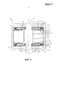
фиг. 1 представляет собой схематичный вид сбоку в сечении электромеханического генератора для преобразования механической вибрационной энергии в электрическую энергию в соответствии с первым вариантом осуществления настоящего изобретения;FIG. 1 is a schematic cross-sectional side view of an electromechanical generator for converting mechanical vibrational energy into electrical energy in accordance with a first embodiment of the present invention;
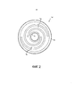
фиг. 2 представляет собой схематичный вид в плане первого устройства смещения электромеханического генератора по фиг. 1;FIG. 2 is a schematic plan view of a first bias device of the electromechanical generator of FIG. one;
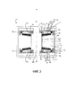
фиг. 3 представляет собой схематичный вид сбоку в сечении электромеханического генератора для преобразования механической вибрационной энергии в электрическую энергию в соответствии со вторым вариантом осуществления настоящего изобретения;FIG. 3 is a schematic cross-sectional side view of an electromechanical generator for converting mechanical vibrational energy into electrical energy in accordance with a second embodiment of the present invention;
фиг. 4 представляет собой схематичный вид сбоку в сечении электромеханического генератора для преобразования механической вибрационной энергии в электрическую энергию в соответствии с третьим вариантом осуществления настоящего изобретения;FIG. 4 is a schematic cross-sectional side view of an electromechanical generator for converting mechanical vibrational energy into electrical energy in accordance with a third embodiment of the present invention;
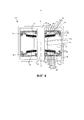
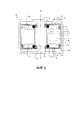
фиг. 5 представляет собой схематичный вид сбоку в сечении электромеханического генератора для преобразования механической вибрационной энергии в электрическую энергию в соответствии с четвертым вариантом осуществления настоящего изобретения.FIG. 5 is a schematic cross-sectional side view of an electromechanical generator for converting mechanical vibrational energy into electrical energy in accordance with a fourth embodiment of the present invention.
Электромеханический генератор по этим вариантам осуществления настоящего изобретения представляет собой резонансный генератор, известный в соответствующей области техники как генератор "с затуханием скорости", в котором вся работа, произведенная движением массы относительно тела, пропорциональна мгновенной скорости этого движения. Часть этой работы неизбежно поглощается, преодолевая нежелательные механические или электрические потери, но остающаяся работа может быть использована для генерации электрического тока посредством соответствующего механизма преобразования, такого как описанная ниже сборка электрическая катушка-магнит. The electromechanical generator according to these embodiments of the present invention is a resonant generator, known in the relevant field of technology as a “speed damping” generator, in which all the work produced by the movement of the mass relative to the body is proportional to the instantaneous speed of this movement. Part of this work is inevitably absorbed, overcoming undesirable mechanical or electrical losses, but the remaining work can be used to generate electric current through an appropriate conversion mechanism, such as the assembly of an electric coil-magnet described below.
Фиг. 1 показывает электромеханический генератор 100 для преобразования механической вибрационной энергии в электрическую энергию в соответствии с первым вариантом осуществления настоящего изобретения. Электромеханический генератор 100 содержит кольцеобразную массу 10, упруго подсоединенную к телу 20 и выполненную с возможностью совершать колебания у точки равновесия относительно тела 20 с амплитудой колебаний. На фиг. 1 масса 10 показана в точке равновесия. Масса 10 является подвижной относительно тела 20 вдоль оси А-А в виде входной механической вибрации, имеющей составляющую в этом линейном направлении. В этом варианте осуществления масса 10 является вращательно-симметричной относительно оси А-А и имеет центральное отверстие по центру которого проходит ось А-А. Масса 10 радиально отделена от центральной части тела 20 зазором G.FIG. 1 shows an
Масса 10 соединена с телом 20 парой смещающих устройств 30, 50, каждое из которых представляет собой плоскую пружину круговой кольцевой формы и содержит множество искривленных консольных элементов. Смещающие устройства 30, 50 удалены одно от другого вдоль оси А-А, при этом масса 10 расположена между ними, и каждое из смещающих устройств 30, 50 смещает массу 10 в соответствующее одно из двух противоположных направлений, параллельных оси А-А, в направлении точки равновесия. The
Масса 10 имеет первый кольцевой выступ 13, который продолжается в осевом направлении от первого аксиального конца основной части 12 массы 10, и второй кольцевой выступ 15, который продолжается в осевом направлении от второго аксиального конца основной части 12 массы 10, при этом второй аксиальный конец является противоположным первому аксиальному концу. Каждый из первого и второго кольцевых выступов 13, 15 является круговым относительно оси А-А, проходящей через центр круга. Первое смещающее устройство 30 из этой пары имеет радиальный внутренний конец 32, подсоединенный или прикрепленный к центральной части 24 тела 20, и радиальный внешний конец 34, подсоединенный или прикрепленный к массе 10 радиально с внешней стороны первого кольцевого выступа 13. Радиальные внутренние и внешние концы 32, 34 первого смещающего устройства 30 соединены между собой центральным участком 36 первого смещающего устройства 30, который имеет размер, параллельный оси А-А, меньший, чем соответствующие размеры, параллельные оси А-А, каждого из радиальных внутренних и внешних концов 32, 34. Аналогичным образом, второе смещающее устройство 50 из этой пары имеет радиальный внутренний конец 52, подсоединенный или прикрепленный к центральной части 24 тела 20, и противоположный радиальный внешний конец 54, подсоединенный или прикрепленный к массе 10 радиально с внешней стороны второго кольцевого выступа 15. Радиальные внутренние и внешние концы 52, 54 второго смещающего устройства 30 соединены между собой центральным участком 56 первого смещающего устройства 50, который имеет размер, параллельный оси А-А, меньший, чем соответствующие размеры, параллельные оси А-А, каждого из радиальных внутренних и внешних концов 52, 54. The
Фиг. 2 показывает пример формы первого смещающего устройства 30. Взятое в качестве примера первое смещающее устройство 30 представляет собой плоскую пружину, предпочтительно, выполненную из металла, такого как пружинная сталь. Как показано на фиг. 2, смещающее устройство 30 имеет множественные спиральные пространства 36, продолжающиеся между радиальным внутренним концом 32 и радиальным внешним концом 34. Внутренний конец 32 определяет внутреннюю окружную сторону смещающего устройства 30, а внешний конец 34 определяет внешнюю окружную сторону смещающего устройства 30. Каждая из спиральных пространств 36 составляет центральный участок 36 консольного элемента первого смещающего устройства 30. Как можно видеть на фиг. 2, первое смещающее устройство 30 содержит два спиральных пространства 36 и, таким образом, два криволинейных консольных элемента. В альтернативном варианте осуществления первое смещающее устройство 30 может содержать только один криволинейный или прямолинейный консольный элемент, или же более чем два криволинейных или прямолинейных консольных элемента. В любом варианте осуществления второе смещающее устройство 50, предпочтительно, имеет такую же форму, что и первое смещающее устройство 30. FIG. 2 shows an example of the shape of the
Каждый из соответствующих внутренних концов 32, 52 смещающих устройств 30, 50 определяет и окружает отверстие, через которое проходит ось А-А. То есть, можно считать, что каждое из смещающих устройств 30, 50 имеет центральное отверстие, через центр которого проходит ось А-А. Соответственно, каждое из смещающих устройств 30, 50 является концентричным с массой 10. Центральная цилиндрическая часть 24 тела 20, продолжается через соответствующие центральные отверстия устройств 30, 50 с центральной продольной осью центральной части 24 тела 20, являющейся совпадающей с осью А-А. Тело 20 далее содержит корпус 22, продолжающийся от центральной части 24 и окружающий и вмещающий в себя массу 10, а также смещающие устройства 30, 50. Корпус 22 может быть герметично закрыт, так чтобы определенный корпусом 22 объем 26, внутри которого объема 26 расположены масса 10, а также смещающие устройства 30, 50, был изолирован от внешнего пространства корпуса 22 и, таким образом, - от внешнего пространства электромеханического генератора 100. Each of the respective inner ends 32, 52 of the
Электромеханический генератор 100 дополнительно содержит преобразователь, выполненный с возможностью преобразовывать колебания массы 10, то есть, механических вибрационных движений массы 10 у точки равновесия относительно тела 20 в электрическую энергию. На фиг. 1 преобразователь специально не показан, но специалист в данной области легко сможет расположить соответствующий преобразователь в проиллюстрированном электромеханическом генераторе 100 для получения этого эффекта. Преобразователь имеет провода (не показаны), продолжающиеся от него для подсоединения к внешней схеме (не показана). Относительные линейные вибрационные движения или колебания между массой 10 и телом 20 вдоль оси А-А вызывают генерацию преобразователем электрического тока, который выводится посредством этих проводов. The
В вариантах осуществления настоящего изобретения преобразователь, предпочтительно, содержит заключенное в теле 20 первое устройство и заключенное в массе 10 второе устройство, при этом второе устройство электромагнитным образом связано с первым устройством. Более предпочтительно, первое устройство зафиксировано относительно корпуса 22 тела 20. In embodiments of the present invention, the converter preferably comprises a first device enclosed in the
Альтернативно, первое устройство может образовывать по меньшей мере часть корпуса 22. Когда преобразователь содержит электромагнитно связанные между собой первое и второе устройства, предпочтительно, одно из первого и второго устройств содержит одно из одного или более магнитов, одной или более электропроводящих катушек и элемента из магнитопроницаемого материала, а другое из первого и второго устройств содержит одно из одной или более электропроводящих катушек, одного или более магнитов и комбинации одного или более магнитов и одной или более электропроводящих катушек. Alternatively, the first device may form at least a portion of the
В этом варианте осуществления преобразователь (не показан) содержит заключенное в теле 20 первое устройство, при этом первое устройство содержит катушку, зафиксированную на центральной части 24 тела 20, и заключенное в массе 10 второе устройство, при этом второе устройство содержит два противодействующих цилиндрических магнита, выполненные с возможностью создавать магнитный поток между магнитами и остальной частью массы 10. Катушка расположена радиально между магнитами и остальной частью массы таким образом, что магнитный поток пересекает катушку. Первое устройство электромагнитно связано со вторым устройством.In this embodiment, the transducer (not shown) comprises a first device enclosed in the
В видоизменении этого варианта осуществления преобразователь содержит заключенное в теле 20 первое устройство, при этом первое устройство на радиально внешней стороне 24а центральной части 24 тела 20 содержит цилиндр из магнитопроницаемого материала и зафиксированные вокруг цилиндра две катушки с кольцевым радиальным магнитом между ними, и заключенное в массе 10 второе устройство, при этом второе устройство содержит элемент из магнитопроницаемого материала. И в этом случае первое устройство электромагнитно связано со вторым устройством.In a modification of this embodiment, the converter comprises a first device enclosed in the
Однако, как упоминалось выше, специалист в данной области легко сможет придумать и обеспечить соответствующие альтернативные преобразователи, которые преобразуют колебания массы 10, то есть, механические вибрационные движения массы 10 у точки равновесия относительно тела 20 в электрическую энергию.However, as mentioned above, one skilled in the art can easily come up with and provide appropriate alternative transducers that convert the vibrations of the
Первая поверхность 12а на первом аксиальном конце основной части 12, продолжающаяся радиально внутрь от первого кольцевого выступа 13, и продолжающаяся радиально наружу от радиальной внутренней стороны 12е основной части 12, имеет кольцевую форму и лежит в плоскости, перпендикулярной оси А-А. Масса 10 содержит первую тонкую кольцевую шайбу 14, которая находится в контакте с первой поверхностью 12а и расположена по радиусу внутрь относительно первого кольцевого выступа 13, тем самым первая тонкая шайба 14 удерживается радиально относительно основной части 12 и выставлена концентрично с этой основной частью 12. Аналогично, вторая поверхность 12b на противоположном втором аксиальном конце основной части 12, продолжающаяся радиально внутрь от второго кольцевого выступа 15, и продолжающаяся радиально наружу от радиальной внутренней стороны 12е основной части 12, имеет кольцевую форму и лежит в плоскости, перпендикулярной оси А-А. Масса 10 содержит вторую тонкую кольцевую шайбу 16, которая находится в контакте со второй поверхностью 12b и расположена по радиусу внутрь относительно второго кольцевого выступа 15, тем самым вторая тонкая шайба 16 удерживается радиально относительно основной части 12 и выставлена концентрично с этой основной частью 12.The
Электромеханический генератор 100 дополнительно содержит пару упругих устройств 40, 60, каждое из которых расположено между телом 20 и массой 10. Более конкретно, - каждое из этой пары упругих устройств 40, 60 расположено между одним из смещающих устройств 30, 50 и массой 10. Каждое из упругих устройств 40, 60 имеет коэффициент упругости, который больше чем коэффициенты упругости смещающих устройств 30, 50. Каждое из первого и второго упругих устройств 40, 60 из этой пары является цельным эластичным устройством в виде пружинной шайбы с круговой усеченной конической формой, то есть, тарельчатой шайбой. Каждое из первого и второго упругих устройств 40, 60 имеет непрерывную вращательную симметрию относительно оси А-А и центральное отверстие с центром, через который проходит ось А-А. Соответственно, каждое из первого и второго упругих устройств 40, 60 является концентричным с массой 10 и концентричным с первым и вторым смещающими устройствами 30, 50.The
Первое упругое устройство 40 имеет внутренний участок 44, окружающий и определяющий центральное отверстие первого упругого устройства 40 на первом аксиальном конце первого упругого устройства 40, и внешний участок 42, определяющий внешнюю окружную сторону первого упругого устройства 40 на втором аксиальном конце первого упругого устройства 40, противоположном первому аксиальному концу. Внутренний и внешний участки 44, 42 первого упругого устройства 40 соединены между собой посредством средней части 46 первого упругого устройства 40. The first
Первое упругое устройство 40 расположено радиально внутрь относительно первого кольцевого выступа 13, тем самым первое упругое устройство 40 удерживается в радиальном положении относительно массы 10 и выставлено концентрично с массой 10. Кроме того, первая, внутренняя сторона 41 первого упругого устройства 40 направлена в сторону массы 10 и на внешнем участке 42 находится в контакте с первой тонкой шайбой 14, но является подвижной относительно этой первой тонкой шайбы 14, как пояснено ниже. Соответственно, первое упругое устройство 40, будучи установленным на массе 10, не зафиксировано или зафиксировано относительно массы 10. Внутренняя сторона 41 первого упругого устройства 40 на внутреннем участке 44 и на средней части 46 удалена от массы 10. Кроме того, вторая, внешняя сторона 43, противоположная внутренней стороне 41 первого упругого устройства 40, по всему внешнему участку 42, внутреннему участку 44 и средней части 46 первого упругого устройства 40 направлена в сторону и удалена от первого смещающего устройства 30, по крайней мере, когда эта масса находится в точке равновесия, как показано на фиг. 1. Между первым смещающим устройством 30 и первым кольцевым выступом 13 массы 10 зажато первое пружинное устройство 70, содержащее волнистую шайбу. Первый конец первого пружинного устройства 70 находится в контакте с первым смещающим устройством 30, а второй, противоположный конец первого пружинного устройства 70 находится в контакте и с кольцевым выступом 13, и с внешней стороной 43 первого упругого устройства 40, тем самым первое пружинное устройство 70 смещает внешний участок 42 первого упругого устройства 40 к массе 10. Коэффициент упругости первого пружинного устройства 70 может быть промежуточным между соответствующими коэффициентами упругости первого смещающего устройства 30 и первого упругого устройства 40. The first
Второе упругое устройство 60 имеет внутренний участок 64, окружающий и определяющий центральное отверстие второго упругого устройства 60 на первом аксиальном конце второго упругого устройства 60, и внешний участок 62, определяющий внешнюю окружную сторону второго упругого устройства 60 на втором аксиальном конце второго упругого устройства 60, противоположном первому аксиальному концу. Соответствующие внутренние стороны 41, 61 первого и второго упругих устройств 40, 60 через массу 10 направлены в сторону одна другой. Внутренний и внешний участки 64, 62 второго упругого устройства 60 соединены между собой посредством средней части 66 второго упругого устройства 60.The second
Второе упругое устройство 60 расположено радиально внутрь относительно второго кольцевого выступа 15, тем самым второе упругое устройство 60 удерживается в радиальном положении относительно массы 10 и выставлено концентрично с массой 10. Кроме того, первая, внутренняя сторона 61 второго упругого устройства 60 направлена в сторону массы 10 и на внешнем участке 62 находится в контакте со второй тонкой шайбой 16, но является подвижной относительно этой второй тонкой шайбы 16, как пояснено ниже. Соответственно, второе упругое устройство 60, будучи установленным на массе 10, не зафиксировано или зафиксировано относительно массы 10. Внутренняя сторона 61 второго упругого устройства 60 на внутреннем участке 64 и на средней части 66 удалена от массы 10. Кроме того, вторая, внешняя сторона 63, противоположная внутренней стороне 61 второго упругого устройства 60 по всему внешнему участку 62, внутреннему участку 64 и средней части 66 второго упругого устройства 60 направлена в сторону и удалена от второго смещающего устройства 50, по крайней мере, когда эта масса 10 находится в точке равновесия, как показано на фиг. 1. Между вторым смещающим устройством 50 и вторым кольцевым выступом 15 массы 10 зажато первое пружинное устройство 80, содержащее волнистую шайбу. Первый конец второго пружинного устройства 80 находится в контакте со вторым смещающим устройством 50, а второй, противоположный конец второго пружинного устройства 80 находится в контакте и с кольцевым выступом 15, и с внешней стороной 63 второго упругого устройства 60, тем самым второе пружинное устройство 80 смещает внешний участок 62 второго упругого устройства 60 к массе 10. Коэффициент упругости второго пружинного устройства 80 может быть промежуточным между соответствующими коэффициентами упругости второго смещающего устройства 50 и второго упругого устройства 60.The second
Когда электромеханический генератор 100 подвержен входной механической вибрации, имеющей составляющую в направлении, параллельном оси А-А, масса 10 принуждена совершать колебания у точки равновесия относительно тела 20, тем самым вызывая преобразователем (не показан) преобразование колебаний массы 10 у точки равновесия относительно тела 20 в электрическую энергию. When the
Первому и второму упругим устройствам 40, 60 придана такая форма, и они расположены в зависимости от удаления смещающих устройств 30, 50 от массы 10 и/или, возможно, в зависимости от предела пропорциональности материала, из которого выполнены смещающие устройства 30, 50, таким образом, чтобы масса 10 имела возможность совершать колебания у точки равновесия относительно тела 20 с амплитудой колебаний, не большей, чем предопределенная пороговая амплитуда, без касания первым и вторым упругими устройствами 40, 60 первого и второго смещающих устройств 30, 50. То есть, первое и второе упругие устройства 40, 60 сконфигурированы таким образом, чтобы, когда масса 10 колеблется с амплитудой, не большей, чем предопределенная пороговая амплитуда, они не зажимались между массой 10 и телом 20 (более конкретно - между смещающими устройствами 30, 50 и массой 10). Соответственно, первое и второе упругие устройства 40, 60 не вызывают никаких потерь энергии в электромеханическом генераторе 100, когда амплитуда колебаний массы 10 - не больше, чем предопределенная пороговая амплитуда. The first and second
Однако, когда (и только тогда, когда) амплитуда колебаний превышает предопределенную пороговую амплитуду, первое и второе упругие устройства 40, 60 периодически "перехватывают" первое и второе смещающие устройства 30, 50, то есть, касаются их, и, таким образом, периодически становятся зажатыми между массой 10 и телом 20 (более конкретно, - между первым и вторым смещающими устройствами 30, 50 и массой 10). То есть, первое и второе упругие устройства 40, 60 сжимаются первым и вторым смещающими устройствами 30, 50 и массой 10 в результате того, что первое и второе смещающие устройства 30, 50 во время колебаний массы 10 подходят слишком близко к массе 10, поскольку масса 10, когда осциллирует относительно тела 20, колеблется относительно центральных участков 36, 56 первого и второго смещающих устройств 30, 50. Соответственно, первое и второе упругие устройства 40, 60 действуют как "мягкие" ограничители или ограничительные упоры, которые ограничивают амплитуду колебаний массы 10. However, when (and only when) the amplitude of the oscillations exceeds a predetermined threshold amplitude, the first and second
Эта деформация первого и второго упругих устройств 40, 60 вызывает скольжение их соответствующих внешних участков 42, 62 вдоль первой и второй тонких шайб 14, 16 массы 10. По этой причине для тонких шайб 14, 16 благоприятно использовать твердый материал, а первое и второе упругие устройства 40, 60 было бы предпочтительно изготавливать из материала, который является совместимым с материалом тонких шайб 14, 16. Например, когда тонкие шайбы 14, 16 сделаны из стали, первое и второе упругие устройства 40, 60 могут быть выполнены из фосфорной бронзы. Однако в модификациях первого варианта осуществления тонкие шайбы 14, 16 могут быть опущены, так что при этом соответствующие внешние участки 42, 62 первого и второго упругих устройств 40, 60 напрямую контактируют с массой 10. This deformation of the first and second
Фиг. 3 показывает электромеханический генератор 100 для преобразования механической вибрационной энергии в электрическую энергию в соответствии со вторым вариантом осуществления настоящего изобретения. Подобные компоненты первого и второго вариантов осуществления обозначены одинаковыми ссылочными позициями. Кроме того, для краткости обсуждение второго варианта осуществления будет ограничено признаками, которые отличают между собой первый и второй варианты осуществления. Соответственно, следует предположить, что признаки второго варианта осуществления, на которые нет подробных ссылок или нет ссылок вообще, могут быть такими же самыми, что и соответствующие признаки первого варианта осуществления. Следует понимать, что вышеописанные возможные модификации, внесенные в электромеханический генератор по первому варианту осуществления, в равной степени приложимы и к электромеханическому генератору второго варианта осуществления. FIG. 3 shows an
Во втором варианте осуществления тело 20 и смещающие устройства 30, 50 являются такими же, как и для первого варианта осуществления. Масса 10 по существу та же самая, что и масса 10 первого варианта осуществления, за исключением того, что тонкие шайбы 14, 16 исключены, а первые и вторые поверхности 12а, 12b основной части 12 не лежат в соответствующих плоскостях, перпендикулярных оси А-А. Вместо этого первая и вторая поверхности 12а, 12b у своих соответствующих концов, смежных с первым и вторым кольцевыми выступами 13. 15, еще дальше удалены одна от другой, а у своих соответствующих концов, смежных с радиальной внутренней стороной 12е основной части 12, придвинуты ближе одна к другой. In the second embodiment, the
Как и в первом варианте осуществления, во втором варианте осуществления каждое из пары упругих устройств 40, 60 расположено между одним из смещающих устройств 30, 50 и массой 10, и каждое из первого и второго упругих устройств 40, 60 представляет собой цельное эластичное устройство в виде пружинной шайбы с круговой усеченной конической формой, то есть, тарельчатую шайбу. Каждое из первого и второго упругих устройств 40, 60 имеет непрерывную вращательную симметрию относительно оси А-А и центральное отверстие с центром, через который проходит ось А-А. Соответственно, каждое из первого и второго упругих устройств 40, 60 является концентричным с массой 10 и концентричным с первым и вторым смещающими устройствами 30, 50.As in the first embodiment, in the second embodiment, each of the pair of
Однако, в отличие от первого варианта осуществления, во втором варианте осуществления первое и второе упругие устройства 40, 60 является инвертированными, так что их соответствующие внешние стороны 43, 63 через массу 10 направлены в сторону одна другой, и так, что их соответствующие внутренние стороны 41, 61 направлены одна от другой в разные стороны. Внешние стороны 43, 63 первого и второго упругих устройств 40, 60 направлены в сторону массы 10 и на соответствующих внешних участках 42, 62 находятся в контакте, соответственно, с первой и второй поверхностями 12а, 12b. Внешние стороны 43, 63 на внутренних участках 44, 64 и на средних частях 46, 66 удалены от массы 10. Внутренние стороны 41, 61 первого и второго упругих устройств 40, 60 по всем внешним участкам 42, 62, внутренним участкам 44, 64 и средним частям 46, 66 первого и второго упругих устройств 40, 60 направлены в сторону и удалены, соответственно, от первого и второго смещающих устройств 30, 50. Соответствующие первые концы первого и второго пружинных устройств 70, 80 находятся в контакте с первым и вторым смещающими устройствами 30, 50, соответственно, а соответствующие вторые концы первого и второго пружинных устройств 70, 80 находятся в контакте с соответствующими кольцевыми выступами 15 и с соответствующими внутренними сторонами 41, 61 первого и второго упругих устройств 40, 60, тем самым первое и второе пружинные устройства 70, 80 смещают внешние участки 42, 62 первого и второго упругого устройства 40, 60 к массе 10.However, unlike the first embodiment, in the second embodiment, the first and second
Во втором варианте осуществления к первому и ко второму смещающим устройствам 30, 50 радиально внутрь прикреплена пара твердых устройств 90, 92, упирающихся в их внутренние радиальные концы 32, 52 (в этом варианте осуществления каждое - в виде твердого пружинного кольца, хотя вместо этого в модификациях данного варианта осуществления могут быть использованы твердые устройства с другими формами). Этим твердым устройствам 90, 92 придана такая форма, и они расположены относительно первого и второго смещающих устройств 30, 50, а также относительно первого и второго упругих устройств 40, 60 таким образом, чтобы быть сконфигурированными с возможностью изоляции первого и второго упругих устройств 40, 60 от соответствующих первого и второго смещающих устройств 30, 50, когда первое и второе упругие устройства 40, 60 деформируются между первым и вторым смещающими устройствами 30, 50 и массой 10 во время колебаний массы 10 у точки равновесия с амплитудой, превосходящей предопределенную пороговую амплитуду. Такая конфигурация лучше предохраняет первое и второе смещающие устройства 30, 50 во время периодов колебаний массы 10 с амплитудой, превосходящей предопределенную пороговую амплитуду.In the second embodiment, a pair of
Во втором варианте осуществления масса 10 имеет возможность совершать колебания у точки равновесия относительно тела 20 с амплитудой колебаний, не большей, чем предопределенная пороговая амплитуда, без касания первым и вторым упругими устройствами 40, 60 первого и второго твердых устройств 90, 92. Однако, когда (и только тогда, когда) амплитуда колебаний превышает предопределенную пороговую амплитуду, первое и второе упругие устройства 40, 60 периодически "перехватывают" твердые устройства 90, 92, то есть, касаются их (но не касаются первого и второго смещающих устройств 30, 50) и таким образом периодически становятся зажатыми между массой 10 и телом 20 (более конкретно, - между первым и вторым смещающими устройствами 30, 50 и массой 10). То есть, как и в первом варианте осуществления, первое и второе упругие устройства 40, 60 сжимаются в результате того, что первое и второе смещающие устройства 30, 50 во время колебаний массы 10 подходят слишком близко к массе 10. Соответственно, первое и второе упругие устройства 40, 60 все еще действуют как "мягкие" ограничители или ограничительные упоры, которые ограничивают амплитуду колебаний массы 10.In the second embodiment, the
Фиг. 4 показывает электромеханический генератор 100 для преобразования механической вибрационной энергии в электрическую энергию в соответствии с третьим вариантом осуществления настоящего изобретения. Подобные компоненты первого, второго и третьего вариантов осуществления обозначены одинаковыми ссылочными позициями. Кроме того, для краткости обсуждение третьего варианта осуществления будет ограничено признаками, которые отличают между собой второй и третий варианты осуществления. Соответственно, следует предположить, что признаки третьего варианта осуществления, на которые нет подробных ссылок или нет ссылок вообще, могут быть такими же самыми, что и соответствующие признаки первого или второго вариантов осуществления. Следует понимать, что вышеописанные возможные модификации, внесенные в электромеханический генератор по первому и второму вариантам осуществления, в равной степени приложимы и к электромеханическому генератору третьего варианта осуществления.FIG. 4 shows an
В третьем варианте осуществления тело 20 и смещающие устройства 30, 50 являются такими же, как и для первого варианта осуществления. Масса 10 по существу та же самая, что и масса 10 второго варианта осуществления, за исключением того, что первый и второй кольцевые выступы 13. 15 имеют поверхности, удаленные от соответствующих первой и второй поверхностей 12а, 12b, которые не лежат в плоскости, перпендикулярной оси А-А. Вместо этого эти удаленные поверхности на своих радиально "наиболее внешних" концах еще больше удалены одна от другой, а на своих радиально "наименее внешних" концах придвинуты ближе одна к другой.In the third embodiment, the
В третьем варианте осуществления первое и второе пружинные устройства 70, 80 содержат конические пружинные шайбы 70, 80. Тем не менее, эти конические пружинные шайбы 70, 80 прилагают к первому и второму упругим устройствам 40, 60 соответствующие нагрузки, почти таким же образом, как это делают первое и второе пружинные устройства 70, 80 в первом и во втором вариантах осуществления.In a third embodiment, the first and
Как и во втором варианте осуществления, каждое из первого и второго упругих устройств 40, 60 расположено между одним из смещающих устройств 30, 50 и массой 10, и каждое из первого и второго упругих устройств 40, 60 является цельным эластичным устройством в виде пружинной шайбы с круговой усеченной конической формой, то есть, тарельчатой шайбой. Каждое из первого и второго упругих устройств 40, 60 имеет непрерывную вращательную симметрию относительно оси А-А и центральное отверстие с центром, через который проходит ось А-А. Соответственно, каждое из первого и второго упругих устройств 40, 60 является концентричным с массой 10 и концентричным с первым и вторым смещающими устройствами 30, 50. Кроме того, во втором варианте осуществления первое и второе упругие устройства 40, 60 является инвертированными, так что их соответствующие внешние стороны 43, 63 через массу 10 направлены в сторону одна другой, и так, что их соответствующие внутренние стороны 41, 61 направлены одна от другой в разные стороны.As in the second embodiment, each of the first and second
В третьем варианте осуществления твердые устройства 90, 92 исключены. Масса 10 имеет возможность совершать колебания у точки равновесия относительно тела 20 с амплитудой колебаний, не большей, чем предопределенная пороговая амплитуда, без касания первым и вторым упругими устройствами 40, 60 первого и второго смещающих устройств 30, 50. Однако, как и в первом варианте осуществления, когда (и только тогда, когда) амплитуда колебаний превышает предопределенную пороговую амплитуду, первое и второе упругие устройства 40, 60 периодически "перехватывают" первое и второе смещающие устройства 30, 50, то есть, касаются их, и, таким образом, периодически становятся зажатыми между массой 10 и телом 20 (более конкретно - между первым и вторым смещающими устройствами 30, 50 и массой 10). То есть, как и в первом варианте осуществления, первое и второе упругие устройства 40, 60 сжимаются первым и вторым смещающими устройствами 30, 50 и массой 10 в результате того, что первое и второе смещающие устройства 30, 50 во время колебаний массы 10 подходят слишком близко к массе 10. Соответственно, первое и второе упругие устройства 40, 60 все еще действуют как "мягкие" ограничители или ограничительные упоры, которые ограничивают амплитуду колебаний массы 10.In the third embodiment,
Фиг. 5 показывает электромеханический генератор 100 для преобразования механической вибрационной энергии в электрическую энергию в соответствии с четвертым вариантом осуществления настоящего изобретения. Подобные компоненты первого и четвертого вариантов осуществления обозначены одинаковыми ссылочными позициями. Кроме того, для краткости обсуждение четвертого варианта осуществления будет ограничено признаками, которые отличают между собой первый и четвертый варианты осуществления. Соответственно, следует предположить, что признаки четвертого варианта осуществления, на которые нет подробных ссылок или нет ссылок вообще, могут быть такими же самыми, что и соответствующие признаки первого варианта осуществления. Следует понимать, что вышеописанные возможные модификации, внесенные в электромеханический генератор по первому варианту осуществления, в равной степени приложимы и к электромеханическому генератору четвертого варианта осуществления. FIG. 5 shows an
В четвертом варианте осуществления тело 20 и смещающие устройства 30, 50 являются такими же, как и для первого варианта осуществления. Масса 10 по существу та же самая, что и масса 10 первого варианта осуществления, за исключением того, что тонкие шайбы 14, 16 исключены. В четвертом варианте осуществления исключены также первое и второе пружинные устройства 70, 80. In the fourth embodiment, the
Кроме того, первое и второе упругие устройства 40, 60 четвертого варианта осуществления - другой формы по сравнению с первым и вторым упругими устройствами 40, 60 первого варианта осуществления. В четвертом варианте осуществления первое и второе упругие устройства 40, 60 содержат соответствующие упругие уплотнительные кольца, установленные на первом и втором смещающих устройствах 30, 50 радиально внутрь, упираясь в их соответствующие внутренние концы 32, 52. Как показано на фиг. 5, когда масса 10 находится в своей точке равновесия, эти уплотнительные кольца удалены от массы 10. В модификациях данного варианта осуществления каждое уплотнительное кольцо может быть заменено или дополнено каким-нибудь эластомерным устройством. In addition, the first and second
В четвертом варианте осуществления масса 10 имеет возможность совершать колебания у точки равновесия относительно тела 20 с амплитудой колебаний, не большей, чем предопределенная пороговая амплитуда, без касания первым и вторым упругими устройствами 40, 60 массы 10. Однако, когда (и только тогда, когда) амплитуда колебаний превышает предопределенную пороговую амплитуду, первое и второе упругие устройства 40, 60 периодически "перехватывают" массу 10, то есть, касаются ее и, таким образом, периодически становятся зажатыми между массой 10 и телом 20 (более конкретно, - между первым и вторым смещающими устройствами 30, 50 и массой 10). То есть, как и в первом варианте осуществления, первое и второе упругие устройства 40, 60 сжимаются в результате того, что первое и второе смещающие устройства 30, 50 во время колебаний массы 10 подходят слишком близко к массе 10. Соответственно, первое и второе упругие устройства 40, 60, содержащие соответствующие уплотнительные кольца, все еще действуют как "мягкие" ограничители или ограничительные упоры, которые ограничивают амплитуду колебаний массы 10.In the fourth embodiment, the
Теоретически, в устройствах за рамками объема настоящего изобретения для того, чтобы ограничить амплитуду колебаний массы 10 в попытке предохранить смещающие устройства 30, 50 и массу 10, а также (или) тело 20 могли бы быть обеспечены твердые (то есть, металлические) ограничительные упоры. Однако воплощающие настоящее изобретение электромеханические генераторы 100 могут быть подвержены неоднократным сильным ударам, достаточным для того, чтобы повторяющимися воздействиями повредить твердые ограничительные упоры. Таким образом, в соответствии с вариантами осуществления настоящего изобретения вместо твердых ограничительных упоров в уже существующем специальном пространстве между смещающими устройствами 30, 50 и одним из массы 10 и тела 20 расположены упругие или "мягкие" устройства 40, 60, не просто для того, чтобы поглощать некоторую часть кинетической энергии осциллирующей массы 10, а и для того, чтобы делать это с использованием очень компактной конструкции. Theoretically, in devices outside the scope of the present invention, in order to limit the amplitude of oscillations of the mass 10 in an attempt to protect the
В вышеописанных электромеханических генераторах, воплощающих настоящее изобретение, упругие устройства 40, 60 могут быть сконфигурированы таким образом, что смещающие устройства 30, 50 все же будут в небольшой степени ударяться о массу 10 и (или) тело 20, когда эти упругие устройства 40, 60 деформируются между смещающими устройствами 30, 50 и массой 10 и (или) телом 20. Однако, упругие устройства 40, 60, предпочтительно, сконфигурированы (то есть, выполнены в таких размерах и имеют такой подобранный коэффициент упругости пружины) таким образом, чтобы избегать таких ударных явлений.In the above-described electromechanical generators embodying the present invention, the
Любой из вышеописанных электромеханических генераторов, воплощающих настоящее изобретение, может быть включен в неподрессоренную массу транспортного средства, соединен с ней, или установлен на ней или на осевой буксе для транспортного средства, предпочтительно - через упругое соединение, такое как эластомерное соединение, которое может быть цельным. Any of the above-described electromechanical generators embodying the present invention can be included in the unsprung mass of the vehicle, connected to it, or mounted on it or on the axle axle for the vehicle, preferably through an elastic connection, such as an elastomeric connection, which can be integral .
Специалистам в данной области будут очевидны другие модификации и варианты осуществления настоящего изобретения. Other modifications and embodiments of the present invention will be apparent to those skilled in the art.
Например, в каждом из вышеописанных вариантов осуществления первое и второе упругие устройства 40, 60 расположены, соответственно, между массой 10 и первым и вторым смещающими устройствами 30, 50. В модификациях этих вариантов осуществления первое и второе упругие устройства 40, 60 альтернативно или дополнительно расположены, соответственно, между телом 20 и первым и вторым смещающими устройствами 30, 50. В таких модификациях, когда (и только тогда, когда) амплитуда колебаний массы 10 превышает предопределенную пороговую амплитуду, первое и второе упругие устройства 40, 60 периодически становятся зажатыми между массой 10 и телом 20 (более конкретно, - между первым и вторым смещающими устройствами 30, 50 и телом 20). То есть, первое и второе упругие устройства 40, 60 сжимаются в результате того, что первое и второе смещающие устройства 30, 50 во время осцилляций массы 10 подходят слишком близко к корпусу 20, поскольку первое и второе смещающие устройства 30, 50 в результате колебаний массы 10 относительно тела 20 двигаются относительно тела 20. Соответственно, в таких модификациях первое и второе упругие устройства 40, 60 еще действуют как "мягкие" ограничители или ограничительные упоры, которые ограничивают амплитуду колебаний массы 10.For example, in each of the above embodiments, the first and second
Кроме того, в других модификациях вышеописанных вариантов осуществления первая и вторая тонкие шайбы 14, 16 могут быть заменены другими соответствующими кольцевыми или некольцевыми компонентами массы 10, которые обеспечивают прочное посадочное место для первого и второго упругих устройств 40, 60. Например, могут быть использованы соответствующие удерживающие кольца. In addition, in other modifications of the above embodiments, the first and second
Более того, в других модификациях вышеописанных вариантов осуществления первое и второе упругие устройства 40, 60 могут содержать соответствующие винтовые пружины, объемы упругого материала, эластомерные устройства или отливки или другие упругие элементы. Moreover, in other modifications of the above embodiments, the first and second
Далее, в дальнейших модификациях вышеописанных вариантов осуществления преобразователь может содержать пьезоэлектрический элемент, который введен вместо электромагнитно связанных первого и второго устройств или вместе с ними. Этот пьезоэлектрический элемент должен бы быть расположенным таким образом, чтобы осцилляции массы относительно тела вызывали деформацию пьезоэлектрического элемента, а преобразователь должен бы быть сконфигурирован таким образом, чтобы преобразовывать деформацию пьезоэлектрического элемента в электроэнергию.Further, in further modifications of the above-described embodiments, the transducer may comprise a piezoelectric element, which is inserted instead of or together with the electromagnetically coupled first and second devices. This piezoelectric element should be positioned so that mass oscillations with respect to the body cause deformation of the piezoelectric element, and the transducer should be configured so that the deformation of the piezoelectric element is converted to electricity.
Claims (44)
Applications Claiming Priority (3)
| Application Number | Priority Date | Filing Date | Title |
|---|---|---|---|
| GB1220417.8 | 2012-11-13 | ||
| GB1220417.8A GB2507132B (en) | 2012-11-13 | 2012-11-13 | An electromechanical generator for, and method of, converting mechanical vibrational energy into electrical energy |
| PCT/EP2013/073754 WO2014076143A2 (en) | 2012-11-13 | 2013-11-13 | An electromechanical generator for, and method of, converting mechanical vibrational energy into electrical energy |
Publications (2)
| Publication Number | Publication Date |
|---|---|
| RU2015122896A RU2015122896A (en) | 2017-01-10 |
| RU2644573C2 true RU2644573C2 (en) | 2018-02-13 |
Family
ID=47470531
Family Applications (1)
| Application Number | Title | Priority Date | Filing Date |
|---|---|---|---|
| RU2015122896A RU2644573C2 (en) | 2012-11-13 | 2013-11-13 | Electromechanical generator and method for coversion of mechanical vibrational energy to electric energy |
Country Status (8)
| Country | Link |
|---|---|
| US (3) | US9941822B2 (en) |
| EP (1) | EP2920869B1 (en) |
| JP (1) | JP6328653B2 (en) |
| CN (3) | CN106195105B (en) |
| AU (1) | AU2013346898B2 (en) |
| GB (3) | GB2507880B (en) |
| RU (1) | RU2644573C2 (en) |
| WO (1) | WO2014076143A2 (en) |
Families Citing this family (17)
| Publication number | Priority date | Publication date | Assignee | Title |
|---|---|---|---|---|
| GB2507880B (en) * | 2012-11-13 | 2015-03-04 | Perpetuum Ltd | An electromechanical generator for, and method of, converting mechanical vibrational energy into electrical energy |
| CN105591515B (en) * | 2014-10-20 | 2018-05-18 | 曾胜克 | Power generator and the object using power generator |
| TR201900402T4 (en) * | 2015-03-31 | 2019-02-21 | Koninklijke Philips Nv | Energy generation system and method. |
| CN105515442B (en) * | 2015-12-04 | 2017-12-12 | 国网江西省电力科学研究院 | A kind of mortar type piezoelectric harvester |
| RU173915U1 (en) * | 2017-01-20 | 2017-09-19 | Федеральное государственное бюджетное образовательное учреждение высшего образования "Омский государственный университет путей сообщения" | POWER SUPPLY DEVICE FOR DIAGNOSTING THE TECHNICAL CONDITION OF THE CARGO WAGON |
| FR3068539A1 (en) * | 2017-06-30 | 2019-01-04 | Commissariat A L'energie Atomique Et Aux Energies Alternatives | ELECTROMAGNETIC ENERGY CONVERTER |
| GB2572350B (en) * | 2018-03-27 | 2023-01-25 | Hitachi Rail Ltd | An electromechanical generator for converting mechanical vibrational energy into electrical energy |
| GB2572348B (en) * | 2018-03-27 | 2020-08-19 | Perpetuum Ltd | An electromechanical generator for converting mechanical vibrational energy into electrical energy |
| GB2572349B (en) * | 2018-03-27 | 2021-08-11 | Perpetuum Ltd | An electromechanical generator for converting mechanical vibrational energy into electrical energy |
| CN108718161B (en) * | 2018-05-31 | 2019-07-12 | 北京工业大学 | A kind of piezo-electric generating floor |
| DE102019200049A1 (en) | 2019-01-04 | 2020-07-09 | Aktiebolaget Skf | A SUSPENSION ASSEMBLY |
| DE102019200048A1 (en) | 2019-01-04 | 2020-07-09 | Aktiebolaget Skf | Suspension spring |
| KR102177140B1 (en) * | 2019-01-18 | 2020-11-10 | 효성중공업 주식회사 | Actuator |
| CN113595441B (en) * | 2020-04-30 | 2023-12-08 | 维沃移动通信有限公司 | Motor and electronic device |
| CN112172412A (en) * | 2020-09-28 | 2021-01-05 | 杭州昌墨科技有限公司 | Shock attenuation wheel suitable for portable computer auxiliary equipment |
| CN112886863B (en) * | 2021-02-01 | 2022-05-27 | 天地(常州)自动化股份有限公司 | Electromagnetic vibration energy collector |
| CN114033605B (en) * | 2021-11-26 | 2023-05-12 | 浙江师范大学 | Piezoelectric wave energy generator |
Citations (8)
| Publication number | Priority date | Publication date | Assignee | Title |
|---|---|---|---|---|
| WO1999049556A1 (en) * | 1998-03-25 | 1999-09-30 | Detra S.A. | Converter of mechanical energy into electric energy and apparatus equipped with same |
| EP1932230A1 (en) * | 2005-10-04 | 2008-06-18 | Perpetuum Ltd. | Generator for converting mechanical vibrational energy into electrical energy |
| US20080265692A1 (en) * | 2007-04-27 | 2008-10-30 | Perpetuum Ltd. | Electromechanical Generator for Converting Mechanical Vibrational Energy Into Electrical Energy |
| GB2446685B (en) * | 2007-11-27 | 2009-04-01 | Perpetuum Ltd | An electromechanical generator for converting mechanical vibrational energy into electrical energy |
| JP2011517277A (en) * | 2008-04-15 | 2011-05-26 | パーペトゥーム、リミテッド | Electromechanical generator and method for converting mechanical vibrational energy into electrical energy |
| RU2421629C2 (en) * | 2006-08-14 | 2011-06-20 | Роузмаунт, Инк. | Damper of machine (versions) and system for utilisation of vibration energy equipped with such damper |
| US20110193427A1 (en) * | 2010-01-06 | 2011-08-11 | Tremont Electric, Llc | Electrical energy generator |
| RU2439771C1 (en) * | 2010-11-22 | 2012-01-10 | Эдвид Иванович Линевич | Vibration power generator |
Family Cites Families (23)
| Publication number | Priority date | Publication date | Assignee | Title |
|---|---|---|---|---|
| JPS4980281U (en) | 1972-10-27 | 1974-07-11 | ||
| CA1022647A (en) * | 1974-02-13 | 1977-12-13 | National Research Council Of Canada | Shock actuated electrical pulse generator |
| US6291901B1 (en) * | 2000-06-13 | 2001-09-18 | ćEFO NEVRES | Electrical power generating tire system |
| WO2005036728A2 (en) * | 2003-07-30 | 2005-04-21 | The Boeing Company | Strain energy shuttle apparatus and method for vibration energy harvesting |
| US7312557B2 (en) * | 2004-08-11 | 2007-12-25 | Omnitek Partners Llc | Mass-spring unit for generating power by applying a cyclic force to a piezoelectric member due to an acceleration of the mass-spring unit |
| EP1803168A4 (en) * | 2004-10-21 | 2009-05-20 | Michelin Soc Tech | A miniaturized piezoelectric based vibrational energy harvester |
| DE102005000996A1 (en) * | 2005-01-07 | 2006-07-20 | Continental Teves Ag & Co. Ohg | Tire module and pneumatic tire with tire module |
| US7554224B2 (en) | 2006-02-22 | 2009-06-30 | Perpetuum Ltd. | Electromechanical generator for converting mechanical vibrational energy into electrical energy |
| US7839058B1 (en) * | 2007-01-29 | 2010-11-23 | Microstrain, Inc. | Wideband vibration energy harvester |
| US20080191584A1 (en) * | 2007-02-08 | 2008-08-14 | Malkin Matthew C | Spring disc energy harvester apparatus and method |
| US8541927B2 (en) * | 2007-11-13 | 2013-09-24 | Kohei Hayamizu | Power generation unit and light emitting tool |
| GB2469347B (en) * | 2009-08-26 | 2011-10-05 | Perpetuum Ltd | An electromechanical generator for converting mechanical vibrational energy into electrical energy |
| JP2011069402A (en) | 2009-09-24 | 2011-04-07 | Ntn Corp | Bearing device with power generation function, and bearing device for vehicle using the same |
| KR20110042745A (en) * | 2009-10-20 | 2011-04-27 | 삼성전기주식회사 | Linear vibration generator |
| CN102148587A (en) * | 2010-02-05 | 2011-08-10 | 边义祥 | Combined type piezoelectric generating set |
| US8525392B2 (en) * | 2010-02-13 | 2013-09-03 | Omnitek Partners Llc | Generators for very-high-G energy harvesting |
| JP2012135131A (en) | 2010-12-22 | 2012-07-12 | Panasonic Corp | Power generation apparatus |
| KR101220247B1 (en) * | 2010-12-23 | 2013-01-09 | 전자부품연구원 | Piezo power generator for emergency power feeding |
| US8912710B2 (en) * | 2011-02-20 | 2014-12-16 | Omnitek Partners Llc | Energy harvesting from input impulse with motion doubling mechanism for generating power from mortar tube firing impulses and other inputs |
| WO2012137695A1 (en) * | 2011-04-07 | 2012-10-11 | 株式会社村田製作所 | Piezoelectric power generator |
| JP4993030B1 (en) | 2011-08-26 | 2012-08-08 | 加納 照彦 | Linear generator |
| US8866316B2 (en) * | 2012-06-21 | 2014-10-21 | General Electric Company | Tunable vibration energy harvester and method |
| GB2507880B (en) * | 2012-11-13 | 2015-03-04 | Perpetuum Ltd | An electromechanical generator for, and method of, converting mechanical vibrational energy into electrical energy |
-
2012
- 2012-11-13 GB GB1318655.6A patent/GB2507880B/en active Active
- 2012-11-13 GB GB1404431.7A patent/GB2518918B/en active Active
- 2012-11-13 GB GB1220417.8A patent/GB2507132B/en active Active
-
2013
- 2013-11-13 JP JP2015541188A patent/JP6328653B2/en active Active
- 2013-11-13 CN CN201610845331.4A patent/CN106195105B/en not_active Expired - Fee Related
- 2013-11-13 CN CN201380069288.1A patent/CN104956116B/en not_active Expired - Fee Related
- 2013-11-13 WO PCT/EP2013/073754 patent/WO2014076143A2/en active Application Filing
- 2013-11-13 US US14/442,675 patent/US9941822B2/en active Active
- 2013-11-13 EP EP13789368.1A patent/EP2920869B1/en active Active
- 2013-11-13 CN CN201610847770.9A patent/CN106195106B/en not_active Expired - Fee Related
- 2013-11-13 AU AU2013346898A patent/AU2013346898B2/en active Active
- 2013-11-13 RU RU2015122896A patent/RU2644573C2/en active
-
2018
- 2018-03-06 US US15/912,792 patent/US10461670B2/en active Active
- 2018-03-06 US US15/912,774 patent/US10425021B2/en active Active
Patent Citations (8)
| Publication number | Priority date | Publication date | Assignee | Title |
|---|---|---|---|---|
| WO1999049556A1 (en) * | 1998-03-25 | 1999-09-30 | Detra S.A. | Converter of mechanical energy into electric energy and apparatus equipped with same |
| EP1932230A1 (en) * | 2005-10-04 | 2008-06-18 | Perpetuum Ltd. | Generator for converting mechanical vibrational energy into electrical energy |
| RU2421629C2 (en) * | 2006-08-14 | 2011-06-20 | Роузмаунт, Инк. | Damper of machine (versions) and system for utilisation of vibration energy equipped with such damper |
| US20080265692A1 (en) * | 2007-04-27 | 2008-10-30 | Perpetuum Ltd. | Electromechanical Generator for Converting Mechanical Vibrational Energy Into Electrical Energy |
| GB2446685B (en) * | 2007-11-27 | 2009-04-01 | Perpetuum Ltd | An electromechanical generator for converting mechanical vibrational energy into electrical energy |
| JP2011517277A (en) * | 2008-04-15 | 2011-05-26 | パーペトゥーム、リミテッド | Electromechanical generator and method for converting mechanical vibrational energy into electrical energy |
| US20110193427A1 (en) * | 2010-01-06 | 2011-08-11 | Tremont Electric, Llc | Electrical energy generator |
| RU2439771C1 (en) * | 2010-11-22 | 2012-01-10 | Эдвид Иванович Линевич | Vibration power generator |
Also Published As
| Publication number | Publication date |
|---|---|
| GB2507880A (en) | 2014-05-14 |
| US9941822B2 (en) | 2018-04-10 |
| CN106195106A (en) | 2016-12-07 |
| GB2507132A (en) | 2014-04-23 |
| RU2015122896A (en) | 2017-01-10 |
| US20180198385A1 (en) | 2018-07-12 |
| US20180234033A1 (en) | 2018-08-16 |
| GB2518918A (en) | 2015-04-08 |
| GB201318655D0 (en) | 2013-12-04 |
| CN106195105A (en) | 2016-12-07 |
| EP2920869A2 (en) | 2015-09-23 |
| AU2013346898A1 (en) | 2015-07-02 |
| US10425021B2 (en) | 2019-09-24 |
| WO2014076143A2 (en) | 2014-05-22 |
| EP2920869B1 (en) | 2020-07-29 |
| GB2507132B (en) | 2016-07-06 |
| CN104956116B (en) | 2018-01-26 |
| GB2507880B (en) | 2015-03-04 |
| US20160285393A1 (en) | 2016-09-29 |
| CN106195106B (en) | 2019-01-15 |
| US10461670B2 (en) | 2019-10-29 |
| CN106195105B (en) | 2019-02-19 |
| WO2014076143A3 (en) | 2015-06-18 |
| JP2015534453A (en) | 2015-11-26 |
| GB2518918B (en) | 2016-07-06 |
| AU2013346898B2 (en) | 2017-09-07 |
| GB201220417D0 (en) | 2012-12-26 |
| CN104956116A (en) | 2015-09-30 |
| GB201404431D0 (en) | 2014-04-30 |
| JP6328653B2 (en) | 2018-05-23 |
Similar Documents
| Publication | Publication Date | Title |
|---|---|---|
| RU2644573C2 (en) | Electromechanical generator and method for coversion of mechanical vibrational energy to electric energy | |
| JP7234256B2 (en) | Electromechanical generator for converting mechanical vibrational energy into electrical energy | |
| US11152843B2 (en) | Electromechanical generator for converting mechanical vibrational energy into electrical energy | |
| US11632030B2 (en) | Electromechanical generator for converting mechanical vibrational energy with magnets and end cores into electrical energy | |
| CN111971883A (en) | Electromechanical generator for converting mechanical vibrational energy into electrical energy |