RU2643937C2 - Device for detecting chemical indicator - Google Patents
Device for detecting chemical indicator Download PDFInfo
- Publication number
- RU2643937C2 RU2643937C2 RU2015102527A RU2015102527A RU2643937C2 RU 2643937 C2 RU2643937 C2 RU 2643937C2 RU 2015102527 A RU2015102527 A RU 2015102527A RU 2015102527 A RU2015102527 A RU 2015102527A RU 2643937 C2 RU2643937 C2 RU 2643937C2
- Authority
- RU
- Russia
- Prior art keywords
- tube
- angle
- lighting
- tubes
- hole
- Prior art date
Links
Images
Classifications
-
- B—PERFORMING OPERATIONS; TRANSPORTING
- B01—PHYSICAL OR CHEMICAL PROCESSES OR APPARATUS IN GENERAL
- B01L—CHEMICAL OR PHYSICAL LABORATORY APPARATUS FOR GENERAL USE
- B01L9/00—Supporting devices; Holding devices
- B01L9/06—Test-tube stands; Test-tube holders
-
- B—PERFORMING OPERATIONS; TRANSPORTING
- B01—PHYSICAL OR CHEMICAL PROCESSES OR APPARATUS IN GENERAL
- B01L—CHEMICAL OR PHYSICAL LABORATORY APPARATUS FOR GENERAL USE
- B01L1/00—Enclosures; Chambers
-
- B—PERFORMING OPERATIONS; TRANSPORTING
- B01—PHYSICAL OR CHEMICAL PROCESSES OR APPARATUS IN GENERAL
- B01L—CHEMICAL OR PHYSICAL LABORATORY APPARATUS FOR GENERAL USE
- B01L7/00—Heating or cooling apparatus; Heat insulating devices
- B01L7/52—Heating or cooling apparatus; Heat insulating devices with provision for submitting samples to a predetermined sequence of different temperatures, e.g. for treating nucleic acid samples
-
- G—PHYSICS
- G01—MEASURING; TESTING
- G01N—INVESTIGATING OR ANALYSING MATERIALS BY DETERMINING THEIR CHEMICAL OR PHYSICAL PROPERTIES
- G01N21/00—Investigating or analysing materials by the use of optical means, i.e. using sub-millimetre waves, infrared, visible or ultraviolet light
- G01N21/17—Systems in which incident light is modified in accordance with the properties of the material investigated
- G01N21/25—Colour; Spectral properties, i.e. comparison of effect of material on the light at two or more different wavelengths or wavelength bands
- G01N21/29—Colour; Spectral properties, i.e. comparison of effect of material on the light at two or more different wavelengths or wavelength bands using visual detection
-
- G—PHYSICS
- G01—MEASURING; TESTING
- G01N—INVESTIGATING OR ANALYSING MATERIALS BY DETERMINING THEIR CHEMICAL OR PHYSICAL PROPERTIES
- G01N21/00—Investigating or analysing materials by the use of optical means, i.e. using sub-millimetre waves, infrared, visible or ultraviolet light
- G01N21/62—Systems in which the material investigated is excited whereby it emits light or causes a change in wavelength of the incident light
- G01N21/63—Systems in which the material investigated is excited whereby it emits light or causes a change in wavelength of the incident light optically excited
- G01N21/64—Fluorescence; Phosphorescence
-
- B—PERFORMING OPERATIONS; TRANSPORTING
- B01—PHYSICAL OR CHEMICAL PROCESSES OR APPARATUS IN GENERAL
- B01L—CHEMICAL OR PHYSICAL LABORATORY APPARATUS FOR GENERAL USE
- B01L2200/00—Solutions for specific problems relating to chemical or physical laboratory apparatus
- B01L2200/02—Adapting objects or devices to another
- B01L2200/026—Fluid interfacing between devices or objects, e.g. connectors, inlet details
-
- B—PERFORMING OPERATIONS; TRANSPORTING
- B01—PHYSICAL OR CHEMICAL PROCESSES OR APPARATUS IN GENERAL
- B01L—CHEMICAL OR PHYSICAL LABORATORY APPARATUS FOR GENERAL USE
- B01L2300/00—Additional constructional details
- B01L2300/08—Geometry, shape and general structure
- B01L2300/0809—Geometry, shape and general structure rectangular shaped
- B01L2300/0829—Multi-well plates; Microtitration plates
-
- B—PERFORMING OPERATIONS; TRANSPORTING
- B01—PHYSICAL OR CHEMICAL PROCESSES OR APPARATUS IN GENERAL
- B01L—CHEMICAL OR PHYSICAL LABORATORY APPARATUS FOR GENERAL USE
- B01L7/00—Heating or cooling apparatus; Heat insulating devices
-
- G—PHYSICS
- G01—MEASURING; TESTING
- G01N—INVESTIGATING OR ANALYSING MATERIALS BY DETERMINING THEIR CHEMICAL OR PHYSICAL PROPERTIES
- G01N21/00—Investigating or analysing materials by the use of optical means, i.e. using sub-millimetre waves, infrared, visible or ultraviolet light
- G01N21/17—Systems in which incident light is modified in accordance with the properties of the material investigated
- G01N21/25—Colour; Spectral properties, i.e. comparison of effect of material on the light at two or more different wavelengths or wavelength bands
-
- G—PHYSICS
- G01—MEASURING; TESTING
- G01N—INVESTIGATING OR ANALYSING MATERIALS BY DETERMINING THEIR CHEMICAL OR PHYSICAL PROPERTIES
- G01N2201/00—Features of devices classified in G01N21/00
- G01N2201/02—Mechanical
- G01N2201/022—Casings
- G01N2201/0221—Portable; cableless; compact; hand-held
Landscapes
- Health & Medical Sciences (AREA)
- Chemical & Material Sciences (AREA)
- Physics & Mathematics (AREA)
- Life Sciences & Earth Sciences (AREA)
- Biochemistry (AREA)
- General Health & Medical Sciences (AREA)
- Analytical Chemistry (AREA)
- Immunology (AREA)
- Chemical Kinetics & Catalysis (AREA)
- General Physics & Mathematics (AREA)
- Pathology (AREA)
- Clinical Laboratory Science (AREA)
- Spectroscopy & Molecular Physics (AREA)
- Nuclear Medicine, Radiotherapy & Molecular Imaging (AREA)
- Molecular Biology (AREA)
- Apparatus Associated With Microorganisms And Enzymes (AREA)
- Investigating, Analyzing Materials By Fluorescence Or Luminescence (AREA)
- Organic Chemistry (AREA)
- Proteomics, Peptides & Aminoacids (AREA)
- Engineering & Computer Science (AREA)
- Zoology (AREA)
- Wood Science & Technology (AREA)
- Investigating Or Analysing Materials By Optical Means (AREA)
- Non-Portable Lighting Devices Or Systems Thereof (AREA)
- Investigating Or Analysing Materials By The Use Of Chemical Reactions (AREA)
- Biophysics (AREA)
- Biotechnology (AREA)
- Microbiology (AREA)
- Devices For Use In Laboratory Experiments (AREA)
- Bioinformatics & Cheminformatics (AREA)
- General Engineering & Computer Science (AREA)
- Genetics & Genomics (AREA)
- Automatic Analysis And Handling Materials Therefor (AREA)
- Spectrometry And Color Measurement (AREA)
Abstract
Description
ПЕРЕКРЕСТНЫЕ ССЫЛКИ НА РОДСТВЕННЫЕ ЗАЯВКИCROSS RELATIONS TO RELATED APPLICATIONS
Данная заявка испрашивает приоритет предварительной заявки США №61665584, поданной 28 июня 2012 г. в Ведомство США по патентам и товарным знакам, содержание которой полностью включено в настоящее описание посредством ссылки, включая, но не ограничиваясь именно теми частями, которые появляются в дальнейшем, при этом включение посредством ссылки выполнено со следующим условием: в случае если любая часть вышеупомянутой заявки противоречит данной заявке, данная заявка заменяет указанную вышеупомянутую заявку.This application claims the priority of provisional application US No. 61665584, filed June 28, 2012 with the United States Patent and Trademark Office, the contents of which are fully incorporated into this description by reference, including, but not limited to those parts that appear later, when hereby, inclusion by reference is made with the following condition: if any part of the aforementioned application is contrary to this application, this application replaces the aforementioned application.
ЗАЯВЛЕНИЕ ОТНОСИТЕЛЬНО ИССЛЕДОВАНИЯ ИЛИ РАЗВИТИЯ, СПОНСИРУЕМЫХ ИЗ ФЕДЕРАЛЬНОГО БЮДЖЕТАSTATEMENT REGARDING THE RESEARCH OR DEVELOPMENT SPONSORED FROM THE FEDERAL BUDGET
Не применимо.Not applicable.
ПРЕДПОСЫЛКИBACKGROUND
1. Область техники, к которой относится настоящее изобретение1. The technical field to which the present invention relates.
[0001] Настоящее изобретение относится в общем к устройству для бокового наблюдения химического индикатора. Точнее, но не обязательно исключительно, настоящее изобретение относится к простому портативному и недорогому устройству для обнаружения присутствия химического индикатора в реакционном сосуде.[0001] The present invention relates generally to a device for laterally observing a chemical indicator. More precisely, but not necessarily exclusively, the present invention relates to a simple portable and inexpensive device for detecting the presence of a chemical indicator in a reaction vessel.
2. Описание известного уровня техники2. Description of the prior art
[0002] Научным процессам давно способствуют считанные данные, полученные освещением исследуемого химического соединения электромагнитным излучением с различной длиной волн. Например, в области амплификации ДНК используются различные флуоресцентные красители и флуоресцентные зонды для определения амплификации целевой последовательности ДНК. В зависимости от типа используемого флуоресцентного красителя или флуоресцентного зонда флуоресценцию обнаруживают путем воздействия на рассматриваемый флуоресцентный краситель или флуоресцентный зонд соответствующим электромагнитным излучением и рассмотрения результирующей флуоресценции через цветной светофильтр.[0002] The read-only data obtained by illuminating the chemical compound under study with electromagnetic radiation of different wavelengths has long contributed to scientific processes. For example, in the field of DNA amplification, various fluorescent dyes and fluorescent probes are used to determine the amplification of the target DNA sequence. Depending on the type of fluorescent dye or fluorescent probe used, fluorescence is detected by exposing the fluorescent dye or fluorescence probe to the appropriate electromagnetic radiation and viewing the resulting fluorescence through a color filter.
[0003] Это стандартная технология, применяемая для анализа продуктов ПЦР-амплификации. ПЦР-амплификацию обычно выполняют в миниатюрных пробирках. Поскольку выполнение ПЦР может занимать несколько часов, обычно наиболее эффективным, а следовательно предпочтительным, является одновременное осуществление нескольких ПЦР-реакций в одной партии. Для этого несколько реакций осуществляют одновременно в группе пробирок. Из-за требований к площади ПЦР-устройств, группы пробирок наиболее часто размещают в квадратной или круглой конфигурации.[0003] This is the standard technology used to analyze PCR amplification products. PCR amplification is usually performed in miniature tubes. Since PCR can take several hours, it is usually most effective, and therefore preferable, to simultaneously carry out several PCR reactions in one batch. For this, several reactions are carried out simultaneously in a group of test tubes. Due to the space requirements of PCR devices, groups of tubes are most often placed in a square or round configuration.
[0004] Квадратная или круглая конфигурация размещения пробирок, применяемых в традиционном ПЦР-термоциклировании, требует выполнения любого обнаружения флуоресценции путем обзора пробирок сверху с применением источника света, обычно расположенного ниже пробирок, или наоборот. Такая компоновка является неидеальной для обнаружения флуоресценции, так как свет проходит снизу и светит в глаза наблюдателю. Ввиду этого большая часть флуоресценции размывается, затрудняя обнаружение различий флуоресценции. Визуальное обнаружение лучше всего выполнять при обзоре пробирок под углом, более или менее перпендикулярным направлению света, освещающего пробирки. Тем не менее, расположение пробирок в традиционной квадратной или прямоугольной конфигурации затрудняет или делает невозможным обзор сбоку из-за того, что пробирки, наиболее приближенные к наблюдателю, закрывают более отдаленные пробирки от обзора наблюдателя.[0004] The square or round arrangement of tubes used in conventional PCR thermal cycling requires any fluorescence detection by looking at the tubes from above using a light source, usually located below the tubes, or vice versa. Such an arrangement is not ideal for detecting fluorescence, since light passes from below and shines into the eyes of the observer. Because of this, most of the fluorescence is eroded, making it difficult to detect differences in fluorescence. Visual detection is best done when viewing tubes at an angle more or less perpendicular to the direction of light illuminating the tubes. However, the location of the tubes in a traditional square or rectangular configuration makes it difficult or impossible to view from the side due to the fact that the tubes closest to the observer close the more distant tubes from the view of the observer.
[0005] Благодаря более новым и быстрым способам амплификации ДНК нет необходимости в выполнении амплификации крупными партиями. Благодаря более новым способам амплификации можно с оптимальными затратами амплифицировать меньшие партии ДНК. Это позволяет размещать пробирки в один ряд или в несколько рядов, расположенных в шахматном порядке. В свою очередь, это предоставляет возможность обзора пробирок сбоку или под углом, более или менее перпендикулярным направлению освещения.[0005] Thanks to newer and faster DNA amplification methods, amplification is not necessary in large batches. Thanks to newer amplification methods, smaller batches of DNA can be amplified at optimal cost. This allows you to place the tubes in one row or in several rows arranged in a checkerboard pattern. In turn, this provides an opportunity to view the tubes from the side or at an angle more or less perpendicular to the direction of illumination.
[0006] Таким образом, дальнейшее техническое описание раскрывает химический и биохимический детектор, различимый невооруженным глазом, для качественного и количественного обнаружения.[0006] Thus, a further technical description discloses a chemical and biochemical detector, distinguishable to the naked eye, for qualitative and quantitative detection.
[0007] Этот детектор обеспечивает количественное и качественное обнаружение флуоресцентных, фосфоресцентных, люминесцентных, электрохимических или колориметрических результатов. Устройство также можно приспособить к нескольким цветным реакциям, включающим в себя дуплексные, триплексные и мультиплексные реакции более высокого порядка. В одном примере для считанных данных флуоресценции устройство будет выполнено таким образом, чтобы использовать источник (источники) возбуждения, соответствующие репортерному красителю, и фильтрацию результата (результатов), соответствующую изучению, при этом реакции используют источники возбуждения, соответствующие репортерному красителю, и фильтрацию результатов, соответствующую изучению.[0007] This detector provides quantitative and qualitative detection of fluorescent, phosphorescent, luminescent, electrochemical or colorimetric results. The device can also be adapted to several color reactions, including higher-order duplex, triplex and multiplex reactions. In one example, for the read fluorescence data, the device will be configured to use the excitation source (s) corresponding to the reporter dye and filtering the result (s) corresponding to the study, while the reactions use excitation sources corresponding to the reporter dye and filtering the results, relevant to the study.
[0008] Детектор выполнен с возможностью адаптации к любому формату химических или биохимических считанных данных, требуемому для существующего теста. Универсальность системы основывается на двух конструкционных признаках устройства: 1) пользовательские выборы химического и биохимического обнаружения являются многочисленными, поскольку устройство может быть легко приспособлено к любому желаемому источнику освещения и может сочетаться с любым желаемым способом фильтрации. Сочетание вариантов выбора освещения и фильтрации индикатора позволяет настраивать несколько возможных комбинаций флуоресцентных, фосфоресцентных, люминесцентных или колориметрических индикаторов внутри детектора.[0008] The detector is adapted to adapt to any chemical or biochemical readout format required for an existing test. The universality of the system is based on two design features of the device: 1) the user choices of chemical and biochemical detection are numerous, because the device can be easily adapted to any desired light source and can be combined with any desired filtering method. The combination of lighting and filtering options allows you to set up several possible combinations of fluorescent, phosphorescent, luminescent or colorimetric indicators inside the detector.
[0009] Данное устройство позволяет применять широкий диапазон возможных длин волн света в сочетании с флуорофорами и фильтрацией обнаруженных результатов на устройстве, на наблюдателе (очки) или на устройстве и на наблюдателе.[0009] This device allows you to use a wide range of possible wavelengths of light in combination with fluorophores and filtering the detected results on the device, on the observer (glasses) or on the device and on the observer.
[0010] Признаки и преимущества настоящего изобретения будут изложены в следующем описании и будут частично очевидны из описания или могут быть изучены посредством практической реализации настоящего изобретения без чрезмерного проведения экспериментов. Признаки и преимущества настоящего изобретения могут быть реализованы и получены с помощью инструментов и комбинаций, отдельно указанных в приложенной формуле изобретения.[0010] The features and advantages of the present invention will be set forth in the following description and will be partially apparent from the description, or may be learned by practice of the present invention without undue experimentation. The features and advantages of the present invention can be realized and obtained using tools and combinations separately indicated in the attached claims.
КРАТКОЕ ОПИСАНИЕ ГРАФИЧЕСКИХ МАТЕРИАЛОВBRIEF DESCRIPTION OF GRAPHIC MATERIALS
[0011] Признаки и преимущества изобретения станут очевидны из рассмотрения последующего подробного описания, представленного в сочетании с сопроводительными графическими материалами, на которых:[0011] The features and advantages of the invention will become apparent from a consideration of the following detailed description, presented in conjunction with the accompanying drawings, in which:
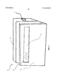
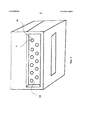
на фиг. 1 показан вид в перспективе устройства;in FIG. 1 shows a perspective view of a device;
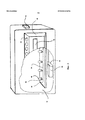
на фиг. 2 показан вид в разобранном состоянии устройства;in FIG. 2 shows an exploded view of the device;
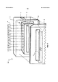
на фиг. 3 показан вид в разрезе устройства;in FIG. 3 shows a sectional view of the device;
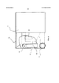
на фиг. 4 показан вид в разрезе еще одного варианта осуществления устройства, содержащего термоблоки;in FIG. 4 is a cross-sectional view of yet another embodiment of a device comprising thermal blocks;
на фиг. 5 показан вид сверху еще одного варианта осуществления устройства, содержащего ряды держателей.in FIG. 5 is a top view of yet another embodiment of a device comprising rows of holders.
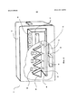
На фиг. 6 показан вид сбоку еще одного варианта осуществления устройства, содержащего поворотное окно.In FIG. 6 is a side view of yet another embodiment of a device comprising a pivot window.
ПОДРОБНОЕ ОПИСАНИЕDETAILED DESCRIPTION
[0012] Для облегчения понимания принципов согласно изобретению далее будут приведены ссылки на варианты осуществления, изображенные на графических материалах, и для их описания будет использована особая терминология. Тем не менее, следует понимать, что этим не предполагается ограничение объема изобретения. Любые изменения и дальнейшие модификации новаторских признаков, изображенных здесь, и любые дополнительные варианты применения принципов изобретения, как изображено здесь, которые могут быть очевидны специалисту в данной области, ознакомленному с данным изобретением, следует считать находящимися в пределах объема заявленного изобретения.[0012] To facilitate understanding of the principles of the invention, reference will now be made to the embodiments depicted in the graphic materials, and specific terminology will be used to describe them. However, it should be understood that this is not intended to limit the scope of the invention. Any changes and further modifications of the innovative features depicted here, and any additional applications of the principles of the invention, as depicted here, which may be obvious to a person skilled in the art familiar with this invention should be considered to be within the scope of the claimed invention.
[0013] Перед раскрытием и описанием настоящего изобретения следует понимать, что данное изобретение не ограничено конкретными конфигурациями, этапами процесса и материалами, описанными здесь, поскольку подобные конфигурации, этапы процесса и материалы могут отличаться в некоторой степени. Также следует понимать, что терминология, примененная здесь, используется лишь с целью описания конкретных вариантов осуществления и не предназначена для ограничения, поскольку объем настоящего изобретения будет ограничен лишь прилагаемой формулой изобретения и ее эквивалентами.[0013] Before disclosing and describing the present invention, it should be understood that the invention is not limited to the specific configurations, process steps, and materials described herein, since such configurations, process steps, and materials may vary to some extent. It should also be understood that the terminology used here is used only to describe specific embodiments and is not intended to be limiting, since the scope of the present invention will be limited only by the appended claims and their equivalents.
[0014] Любые публикации и другие ссылочные материалы, ссылки на которые приведены здесь для описания предпосылок изобретения и для предоставления дополнительных подробностей относительно его практического осуществления, настоящим полностью включены в данное описание посредством ссылки со следующим исключением: В случае если любая часть указанных ссылочных материалов противоречит данной заявке, данная заявка заменяет указанные ссылочные материалы. Ссылочные материалы, описанные здесь, предоставлены исключительно для их раскрытия перед датой подачи настоящей заявки. В данной заявке ничего не должно расцениваться как предположение или допущение того, что авторы изобретения не уполномочены датировать задним числом подобное изобретение на основании предыдущего изобретения или отличать настоящее изобретение от предмета, раскрытого в ссылочных материалах.[0014] Any publications and other reference materials referenced here to describe the premises of the invention and to provide further details regarding its practical implementation, are hereby fully incorporated into this description by reference with the following exception: In case any part of these reference materials contradicts this application, this application replaces the referenced materials. Reference materials described herein are provided solely for their disclosure before the filing date of this application. Nothing in this application should be construed as an assumption or assumption that the inventors are not authorized to retroactively date such an invention based on a previous invention or to distinguish the present invention from the subject disclosed in the referenced materials.
[0015] Следует отметить, что, как используется в данном техническом описании и прилагаемой формуле изобретения, ссылки в форме единственного числа также включают в себя ссылки в форме множественного числа, если в контексте строго не указано иначе.[0015] It should be noted that, as used in this technical description and the attached claims, singular references also include plural references, unless the context clearly indicates otherwise.
[0016] В описании и формуле настоящего изобретения следующая терминология будет использована в соответствии с определениями, изложенными ниже.[0016] In the description and claims of the present invention, the following terminology will be used in accordance with the definitions set forth below.
[0017] Как использовано здесь, термины «содержащий», «включающий в себя», «состоящий из», «отличающийся тем, что» и их грамматические эквиваленты являются включающими или неограничивающими терминами, не исключающими дополнительных, не перечисленных элементов или этапов способа.[0017] As used here, the terms "comprising", "including", "consisting of", "characterized in that" and their grammatical equivalents are inclusive or non-limiting terms that do not exclude additional, not listed elements or steps of the method.
[0018] Как использовано здесь, фраза «состоящий из» и ее грамматические эквиваленты исключают любой элемент, этап или ингредиент, не указанный в формуле изобретения.[0018] As used here, the phrase "consisting of" and its grammatical equivalents exclude any element, step or ingredient not specified in the claims.
[0019] Как использовано здесь, фраза «состоящий по существу из» и ее грамматические эквиваленты ограничивают объем формулы изобретения конкретными материалами или этапами и теми, которые не влияют материально на основную и новаторскую характеристику или характеристики заявленного изобретения.[0019] As used here, the phrase "consisting essentially of" and its grammatical equivalents limit the scope of the claims to specific materials or steps and those that do not materially affect the main and innovative characteristics or characteristics of the claimed invention.
[0020] Как использовано здесь, термин «проксимальный» относится в широком смысле к понятию ближайшего положения.[0020] As used here, the term "proximal" in the broad sense refers to the concept of the nearest position.
[0021] Как использовано здесь, термин «дистальный» в общем относится к положению, противоположному проксимальному, и, таким образом, к понятию отдаленного положения или наиболее отдаленного положения, в зависимости от контекста.[0021] As used here, the term "distal" generally refers to the position opposite to the proximal, and thus to the concept of a distant position or the most distant position, depending on the context.
[0022] Как использовано здесь, фраза «в по меньшей мере частичном направлении от проксимального к дистальному» относится в общем к двухмерному понятию направления, в котором направление «от проксимального к дистальному» определяет одно направление или один размер. Объект, проходящий в направлении, не параллельном направлению «от проксимального к дистальному», то есть под углом к нему, не являющимся прямым, таким образом включает в себя два компонента направления, один из которых находится в направлении «от проксимального к дистальному» и другой находится в направлении, перпендикулярном направлению «от проксимального к дистальному».[0022] As used here, the phrase “in the at least partial direction from the proximal to the distal” refers generally to a two-dimensional concept of a direction in which the “proximal to distal” direction defines one direction or one size. An object extending in a direction not parallel to the “proximal to distal” direction, that is, at an angle to it that is not straight, thus includes two direction components, one of which is in the “proximal to distal” direction and the other is in the direction perpendicular to the direction “from proximal to distal”.
[0023] На фиг. 1 изображено портативное ручное устройство 10, работающее от батареи, для наблюдения за визуальным сигналом химического индикатора. Как изображено на фиг. 1, устройство содержит корпус 14. В одном варианте осуществления размер и форма корпуса 14 позволяют отдельному пользователю легко удерживать его в руке. Корпус 14 содержит выключатель 18, активирующий функцию освещения (не изображено) устройства 10. Устройство 10 также содержит защитный экран 20. Защитный экран 20 прикреплен с возможностью снятия к корпусу 14. Съемный защитный экран 20 содержит отверстие 22. Форма и размер данного отверстия 22 позволяют ему вмещать окно 26. Данное окно 26 может быть изготовлено из стекла, пластика, слюды, любого полимера или другого композитного материала, известного специалистам в данной области. Окно 26 может быть прозрачным или непрозрачным. Окно может быть цветным. В изображенном варианте осуществления окно 26 постоянно прикреплено к защитному экрану 20. Защитный экран 20 может быть отсоединен от корпуса 14. В данном варианте осуществления может быть использовано несколько защитных экранов 20, при этом каждый защитный экран 20 содержит окно 26 другого цвета. Данный вариант осуществления позволяет пользователю заменять окна 26 на окна других цветов путем присоединения других защитных экранов 20 к корпусу 14. Хотя источником питания в варианте осуществления, изображенном на фиг. 1, является батарея, источником питания может быть переменный ток из обычной стенной розетки, солнечная батарея или любой другой источник питания, известный специалистам в данной области.[0023] FIG. 1 depicts a portable battery-powered hand-held
[0024] В еще одном варианте осуществления защитный экран 20 постоянно прикреплен к корпусу 10. В данном варианте осуществления окно 26 прикреплен с возможностью снятия к защитному экрану 20. Это позволяет пользователю использовать окна 26 различных цветов путем извлечения установленного окна 26 и его замены окном 26 желаемого цвета.[0024] In yet another embodiment, the
[0025] На фиг. 2 изображен вид в разобранном состоянии устройства 10. Корпус 14 содержит по меньшей мере одну стойку 40 для пробирок. По меньшей мере одна стойка 40 для пробирок является более или менее полой и содержит гнезда 34, размер и форма которых позволяет вмещать пробирки 38. Пробирки 38 содержат выступы, расположенные на их открытых концах, диаметр которых больше диаметра гнезд 34. Когда пробирки 38 вставлены в гнезда 34, выступы предотвращают полное прохождение пробирок 38 сквозь гнездо 34. Таким образом, стойка 40 для пробирок и гнезда 34 предоставляют конструкцию для подвешивания и поддерживания пробирок в нужном положении для освещения и обзора наблюдателем.[0025] FIG. 2 shows an exploded view of the
[0026] Стойка 40 для пробирок содержит просвет 30, обеспечивающий обзор внутреннего пространства стойки 40 для пробирок. Просвет 30 расположен на одной линии с отверстием 22 в защитном экране 20, так что пользователю предоставлен хороший обзор внутреннего пространства стойки 40 для пробирок. Отверстие 22, а также просвет 30, расположены таким образом, что по меньшей мере часть пробирок 38 видна наблюдателю, так что наблюдатель, смотрящий в окно, смотрит на пробирки 38 в виде более или менее сбоку или менее перпендикулярно относительно продольной оси пробирок 38.[0026] The
[0027] В другом варианте осуществления по меньшей мере одна пробирка 38 может быть подвешена и может удерживаться в своем положении с помощью зажимов, скоб или любых других средств, известных специалистам в данной области. Подобный вариант осуществления не требует стойки 40 для пробирок и просвета 30 и обеспечивает обзор пробирок 38 непосредственно через отверстие.[0027] In another embodiment, at least one
[0028] На фиг. 3 изображен вид в разрезе корпуса 14, предоставляющего обзор электронной архитектуры устройства 10. Согласно данному варианту осуществления корпус содержит монтажную плату 44, электрически связанную с выключателем 18. Электронная архитектура также содержит источник 48 питания, электрически связанный 50 с выключателем 18, так что при включении выключателя 18 энергия поступает от источника 48 питания к монтажной плате 44. Монтажная плата 44 содержит патроны 45, в которые может быть вставлено по меньшей мере одно осветительное устройство 46. Осветительное устройство 46 может представлять собой лампу накаливания, светодиод или любое другое осветительное устройство, знакомое специалистам в данной области. При подаче питания на монтажную плату 44 по меньшей мере одно осветительное устройство 46 освещает пробирки 38. В варианте осуществления, изображенном на фиг. 3, монтажная плата 44 и по меньшей мере одно осветительное устройство 46 расположены ниже гнезд 34, так что когда пробирки 38 подвешены во внутреннем пространстве стойки 40 для пробирок, по меньшей мере одно осветительное устройство освещает пробирку снизу пробирки. Это приводит к тому, что наблюдатель видит пробирки через отверстие и просвет под более или менее прямым углом к направлению света, излученного по меньшей мере одним осветительным устройством 46. Цвет излученного света может быть изменен путем изменения типа осветительного устройства 46. Это можно осуществить путем замены одного или нескольких отдельных осветительных устройств 46 в монтажной плате. В качестве альтернативы это можно осуществить путем отсоединения и извлечения существующей монтажной платы и ее замены монтажной платой, содержащей один или несколько осветительных устройств 46 желаемого цвета. В альтернативном варианте монтажная плата может содержать осветительные устройства 46 разных цветов, выбираемых пользователем. Это может быть выполнено, например, путем присоединения всех осветительных устройств 46 одного цвета к отдельной цепи в монтажной плате и предоставления пользователю возможности подавать питание на одну или несколько цепей, активирующих осветительные устройства, создающие желаемый и определенный цвет химической индикации.[0028] In FIG. 3 is a cross-sectional view of a
[0029] В альтернативном варианте осуществления отверстие 22, а также просвет 30 расположены таким образом, что наблюдатель, смотрящий через окно, видит пробирки под углом 80 градусов или более относительно угла падения света.[0029] In an alternative embodiment, the
[0030] В альтернативном варианте осуществления отверстие 22, а также просвет 30 расположены таким образом, что наблюдатель, смотрящий через окно, видит пробирки под углом 70 градусов или более относительно угла падения света.[0030] In an alternative embodiment, the
[0031] В альтернативном варианте осуществления отверстие 22, а также просвет 30 расположены таким образом, что наблюдатель, смотрящий через окно, видит пробирки под углом 60 градусов или более относительно угла падения света.[0031] In an alternative embodiment, the
[0032] В альтернативном варианте осуществления отверстие 22, а также просвет 30 расположены таким образом, что наблюдатель, смотрящий через окно, видит пробирки под углом 50 градусов или более относительно угла падения света.[0032] In an alternative embodiment, the
[0033] В альтернативном варианте осуществления отверстие 22, а также просвет 30 расположены таким образом, что наблюдатель, смотрящий через окно, видит пробирки под углом 40 градусов или более относительно угла падения света.[0033] In an alternative embodiment, the
[0034] В альтернативном варианте осуществления отверстие 22, а также просвет 30 расположены таким образом, что наблюдатель, смотрящий через окно, видит пробирки под углом 30 градусов или более относительно угла падения света.[0034] In an alternative embodiment, the
[0035] В альтернативном варианте осуществления отверстие 22, а также просвет 30 расположены таким образом, что наблюдатель, смотрящий через окно, видит пробирки под углом 20 градусов или более относительно угла падения света.[0035] In an alternative embodiment, the
[0036] В альтернативном варианте осуществления отверстие 22, а также просвет 30 расположены таким образом, что наблюдатель, смотрящий через окно, видит пробирки под углом 10 градусов или более относительно угла падения света.[0036] In an alternative embodiment, the
[0037] В альтернативном варианте осуществления отверстие 22, а также просвет 30 расположены таким образом, что наблюдатель, смотрящий через окно, видит пробирки под углом 5 градусов или более относительно угла падения света.[0037] In an alternative embodiment, the
[0038] В альтернативном варианте осуществления отверстие 22, а также просвет 30 расположены таким образом, что наблюдатель, смотрящий через окно, видит пробирки под углом 1 градус или более относительно угла падения света.[0038] In an alternative embodiment, the
[0039] В еще одном варианте осуществления, изображенном на фиг.4, устройство содержит группу термоблоков 58, расположенных проксимально к пробиркам 38 таким образом, чтобы находиться в тепловой связи с пробирками 38. Термоблоки 58 электрически связаны с монтажной платой 44, так что при подаче питания на монтажную плату 44 питание подается и на термоблоки 58. Электрическая связь 50 между термоблоками 58 и источником 48 питания может содержать по меньшей мере один резистор 59 или какое-либо другое устройство, известное специалистам в данной области, способное уменьшать силу тока, подаваемого к одному или нескольким термоблокам 58, так что сила тока, поданного к термоблоку с одной стороны пробирки, больше силы тока, поданного к термоблоку 58 с другой стороны пробирки. Данная разница силы тока образует перепад температур между термоблоками 58, достаточный для создания конвекционного течения внутри пробирки. В варианте осуществления, изображенном на фиг. 4, термоблоки 58 более или менее соответствуют форме пробирок 38, обеспечивая равномерный теплообмен между термоблоками 58 и пробирками 38.[0039] In yet another embodiment, shown in FIG. 4, the device comprises a group of
[0040] В еще одном варианте осуществления устройство 10 содержит средство регулировки температур термоблоков. Например, один или несколько реостатов могут быть расположены в электрической схеме между источником питания и термоблоками 58, так что температуру одного или нескольких термоблоков 58 можно изменять. Температурой также можно управлять посредством другого устройства или комбинации устройств, известных специалистам в данной области.[0040] In yet another embodiment, the
[0041] В еще одном варианте осуществления устройство 10 может содержать нагревательный элемент и/или охлаждающий элемент, так что можно организовать термоциклирование устройства в пределах заданного температурного диапазона.[0041] In yet another embodiment, the
[0042] В еще одном варианте осуществления устройство не содержит внутренний источник света, но вместо этого содержит просвет во внутреннее пространство корпуса. Данный просвет может находиться в задней части или в нижней части устройства 10. Размер и форма открытой части позволяют освещению от источника света, расположенного снаружи устройства 10, проходить в устройство 10 и освещать пробирки 38.[0042] In yet another embodiment, the device does not contain an internal light source, but instead contains a lumen in the interior of the housing. This clearance can be located at the rear or at the bottom of the
[0043] В другом варианте осуществления устройство содержит светочувствительный измерительный прибор, регистрирующий длину волны света, излучаемого от пробирки. Светочувствительный измерительный прибор электрически связан с процессором, способным выполнять машиночитаемый код, преобразующий зарегистрированную длину волны в цифровой формат. Эти оцифрованные данные затем можно хранить в запоминающем устройстве, электрически связанном с процессором. Оцифрованные данные также могут быть отображены в устройстве вывода, электрически связанном с процессором и/или запоминающим устройством.[0043] In another embodiment, the device comprises a photosensitive measuring device that records the wavelength of light emitted from the test tube. The light-sensitive measuring device is electrically connected to a processor capable of executing a machine-readable code that converts the recorded wavelength to digital format. This digitized data can then be stored in a memory device electrically connected to the processor. Digitized data may also be displayed in an output device electrically coupled to a processor and / or memory.
[0044] В еще одном варианте осуществления отверстие 22 в защитном экране 20 не содержит окно 26. В данном варианте осуществления наблюдатель использует светофильтр снаружи устройства для того, чтобы сделать индикатор видимым. Например, светофильтр может представлять собой очки с линзами подходящего цвета.[0044] In yet another embodiment, the
[0045] В еще одном варианте осуществления источник света расположен сбоку от пробирок 38 и смотровое отверстие расположено над пробирками 38. В еще одном варианте осуществления источник света расположен сбоку от пробирок 38 и смотровое отверстие расположено под пробирками 38. В еще одном варианте осуществления источник света расположен более или менее над пробирками 38 и смотровое отверстие 22 расположено сбоку от пробирок 38.[0045] In yet another embodiment, the light source is located on the side of the
[0046] В еще одном варианте осуществления, изображенном на фиг. 5, гнезда 34 для пробирок расположены по меньшей мере в два ряда, в шахматном порядке. Как изображено на фиг. 5, гнезда 34 для пробирок расположены в виде первого ряда 64 и второго ряда 60. Гнезда 34 для пробирок расположены в шахматном порядке, так что пробирки 38 во втором ряду 60 не закрываются пробирками 38 в первом ряду 64 от обзора наблюдателя, смотрящего через отверстие.[0046] In another embodiment depicted in FIG. 5, the
[0047] В еще одном варианте осуществления, изображенном на фиг. 6, окна 68 разных цветов встроены в ленточный механизм 70 внутри устройства 10. Ленточный механизм 70 растянут между двумя вращающимися роликами 72. Один из вращающихся роликов соединен с приводным роликом 76. При вращении приводного ролика 76 он заставляет ленточный конвейер двигаться, который, в свою очередь, заставляет окна 68 различных цветов перемещаться между по меньшей мере одним вращающимся роликом 72. Таким образом, пользователь может изменять цвет окон 68 путем управления приводным роликом 76 до тех пор, пока окно желаемого цвета не появится перед отверстием 22. При движении окон 68 разного цвета между вращающимися роликами они последовательно перемещаются мимо отверстия 22. Кроме того, на фиг. 6 изображена крышка 80, прикрепленная к верхней части устройства 10. Крышка 80 выполнена таким образом, чтобы блокировать, по меньшей мере, часть окружающего света.[0047] In yet another embodiment, depicted in FIG. 6,
[0048] В еще одном варианте осуществления устройство 10 является слишком большим для легкого удержания в руке.[0048] In yet another embodiment, the
Claims (22)
Applications Claiming Priority (3)
| Application Number | Priority Date | Filing Date | Title |
|---|---|---|---|
| US201261665584P | 2012-06-28 | 2012-06-28 | |
| US61/665,584 | 2012-06-28 | ||
| PCT/US2013/048750 WO2014005112A1 (en) | 2012-06-28 | 2013-06-28 | A chemical indicator device |
Related Child Applications (1)
| Application Number | Title | Priority Date | Filing Date |
|---|---|---|---|
| RU2018103106A Division RU2018103106A (en) | 2012-06-28 | 2013-06-28 | CHEMICAL INDICATOR DETECTION DEVICE |
Publications (2)
| Publication Number | Publication Date |
|---|---|
| RU2015102527A RU2015102527A (en) | 2016-08-20 |
| RU2643937C2 true RU2643937C2 (en) | 2018-02-06 |
Family
ID=49783929
Family Applications (2)
| Application Number | Title | Priority Date | Filing Date |
|---|---|---|---|
| RU2015102527A RU2643937C2 (en) | 2012-06-28 | 2013-06-28 | Device for detecting chemical indicator |
| RU2018103106A RU2018103106A (en) | 2012-06-28 | 2013-06-28 | CHEMICAL INDICATOR DETECTION DEVICE |
Family Applications After (1)
| Application Number | Title | Priority Date | Filing Date |
|---|---|---|---|
| RU2018103106A RU2018103106A (en) | 2012-06-28 | 2013-06-28 | CHEMICAL INDICATOR DETECTION DEVICE |
Country Status (15)
| Country | Link |
|---|---|
| US (1) | US11293855B2 (en) |
| EP (1) | EP2867652B1 (en) |
| JP (2) | JP6298048B2 (en) |
| KR (1) | KR102277892B1 (en) |
| CN (2) | CN107262177B (en) |
| AU (3) | AU2013282300B2 (en) |
| BR (1) | BR112014032911A2 (en) |
| CA (1) | CA2908930C (en) |
| ES (1) | ES2854987T3 (en) |
| HK (1) | HK1209829A1 (en) |
| IL (1) | IL236481A0 (en) |
| MX (1) | MX350425B (en) |
| NZ (2) | NZ704075A (en) |
| RU (2) | RU2643937C2 (en) |
| WO (1) | WO2014005112A1 (en) |
Families Citing this family (2)
| Publication number | Priority date | Publication date | Assignee | Title |
|---|---|---|---|---|
| CN107262177B (en) * | 2012-06-28 | 2020-07-10 | 弗洛雷森特里克公司 | Chemical indicator device |
| WO2024037302A1 (en) * | 2022-08-16 | 2024-02-22 | 杭州逸检科技有限公司 | Portable nucleic acid detection device, system and method |
Citations (5)
| Publication number | Priority date | Publication date | Assignee | Title |
|---|---|---|---|---|
| US3768526A (en) * | 1970-04-03 | 1973-10-30 | M Sanz | Automatic test tube transporter and sample dispenser |
| WO2002068932A2 (en) * | 2001-02-23 | 2002-09-06 | Genicon Sciences Corporation | Methods for providing extended dynamic range in analyte assays |
| EA007338B1 (en) * | 1999-06-21 | 2006-08-25 | Ричард М. Крис | Method for detecting targets in a sample and kits therefor |
| RU2409817C2 (en) * | 2005-08-16 | 2011-01-20 | Дженентек, Инк. | Analyses and methods of biomarker application |
| WO2012012779A2 (en) * | 2010-07-23 | 2012-01-26 | Beckman Coulter Inc. | System and method including analytical units |
Family Cites Families (71)
| Publication number | Priority date | Publication date | Assignee | Title |
|---|---|---|---|---|
| US5333675C1 (en) | 1986-02-25 | 2001-05-01 | Perkin Elmer Corp | Apparatus and method for performing automated amplification of nucleic acid sequences and assays using heating and cooling steps |
| JPH0515082Y2 (en) | 1986-04-30 | 1993-04-21 | ||
| US6703236B2 (en) | 1990-11-29 | 2004-03-09 | Applera Corporation | Thermal cycler for automatic performance of the polymerase chain reaction with close temperature control |
| DE4440294A1 (en) | 1994-11-11 | 1996-05-15 | Boehringer Mannheim Gmbh | System for the incubation of sample liquids |
| US5958349A (en) | 1997-02-28 | 1999-09-28 | Cepheid | Reaction vessel for heat-exchanging chemical processes |
| AU6343398A (en) | 1997-02-28 | 1998-09-18 | Cepheid | Heat exchanging, optically interrogated chemical reaction assembly |
| US8293064B2 (en) | 1998-03-02 | 2012-10-23 | Cepheid | Method for fabricating a reaction vessel |
| CA2285377C (en) | 1997-03-28 | 2004-08-17 | The Perkin-Elmer Corporation | Improvements in thermal cycler for pcr |
| US6660228B1 (en) | 1998-03-02 | 2003-12-09 | Cepheid | Apparatus for performing heat-exchanging, chemical reactions |
| US6369893B1 (en) | 1998-05-19 | 2002-04-09 | Cepheid | Multi-channel optical detection system |
| US7188001B2 (en) | 1998-03-23 | 2007-03-06 | Cepheid | System and method for temperature control |
| ES2224347T3 (en) * | 1998-05-01 | 2005-03-01 | F. Hoffmann-La Roche Ag | APPARATUS TO SIMULTANEOUSLY CONTROL THE REACTIONS THAT HAVE PLACED A PLURALITY OF REACTION CONTAINERS. |
| US7799521B2 (en) | 1998-06-24 | 2010-09-21 | Chen & Chen, Llc | Thermal cycling |
| GB9826237D0 (en) * | 1998-11-30 | 1999-01-20 | Hybaid Ltd | Thermal cycler |
| DE19859586C1 (en) | 1998-12-22 | 2000-07-13 | Mwg Biotech Ag | Thermal cycler device |
| US6818185B1 (en) | 1999-05-28 | 2004-11-16 | Cepheid | Cartridge for conducting a chemical reaction |
| ATE264718T1 (en) | 1999-07-02 | 2004-05-15 | Clondiag Chip Tech Gmbh | MICROCHIP MATRIX DEVICE FOR THE DUPLICATION AND CHARACTERIZATION OF NUCLEIC ACIDS |
| US6403037B1 (en) | 2000-02-04 | 2002-06-11 | Cepheid | Reaction vessel and temperature control system |
| KR100488281B1 (en) | 2001-09-15 | 2005-05-10 | 아람 바이오시스템 주식회사 | Method and apparatus for amplification of nucleic acid sequences by using thermal convection |
| WO2003029397A1 (en) * | 2001-10-02 | 2003-04-10 | Stratagene | Side-wall heater for thermocycler device |
| JP2003344290A (en) | 2002-05-27 | 2003-12-03 | Aisin Cosmos R & D Co Ltd | Fluorescence detector with temperature controller |
| US7238520B2 (en) | 2002-12-04 | 2007-07-03 | Smiths Detection Inc. | PCR sample preparation holder and method |
| US8676383B2 (en) | 2002-12-23 | 2014-03-18 | Applied Biosystems, Llc | Device for carrying out chemical or biological reactions |
| US7049558B2 (en) * | 2003-01-27 | 2006-05-23 | Arcturas Bioscience, Inc. | Apparatus and method for heating microfluidic volumes and moving fluids |
| WO2004080597A2 (en) | 2003-02-05 | 2004-09-23 | Iquum, Inc. | Sample processing tubule |
| US7442542B2 (en) | 2003-03-24 | 2008-10-28 | Agency For Science, Technology And Research | Shallow multi-well plastic chip for thermal multiplexing |
| JPWO2004095009A1 (en) | 2003-04-24 | 2006-07-13 | 株式会社モリテックス | Optical inspection device |
| US20040241048A1 (en) | 2003-05-30 | 2004-12-02 | Applera Corporation | Thermal cycling apparatus and method for providing thermal uniformity |
| WO2005012518A1 (en) | 2003-07-30 | 2005-02-10 | Riken | Kit for nucleic acid detection |
| WO2005116611A2 (en) | 2003-11-05 | 2005-12-08 | Greg Liang | Flow assay device comprising dry reagent cake |
| US8916348B2 (en) | 2004-05-06 | 2014-12-23 | Clondiag Gmbh | Method and device for the detection of molecular interactions |
| EP2708595A1 (en) | 2004-08-05 | 2014-03-19 | Universal Bio Research Co., Ltd. | Reaction vessel, reaction vessel liquid introducing device, liquid introducing and reaction measuring device, and liquid introducing device |
| US20080003564A1 (en) | 2006-02-14 | 2008-01-03 | Iquum, Inc. | Sample processing |
| US20090061450A1 (en) | 2006-03-14 | 2009-03-05 | Micronics, Inc. | System and method for diagnosis of infectious diseases |
| CN101568636A (en) | 2006-11-02 | 2009-10-28 | 威腾技术公司 | Cartridge for conducting diagnostic assays |
| DK2574681T3 (en) | 2007-03-28 | 2016-07-04 | Signal Diagnostics | System and method for high-resolution analysis of nucleic acids to detect sequence variations |
| JP5205802B2 (en) * | 2007-05-11 | 2013-06-05 | ソニー株式会社 | Real-time PCR device |
| GB0710957D0 (en) | 2007-06-07 | 2007-07-18 | Norchip As | A device for carrying out cell lysis and nucleic acid extraction |
| RU2413770C2 (en) * | 2007-06-14 | 2011-03-10 | Институт биохимии и генетики Уфимского научного центра РАН | Method of carrying out polymerase chain reaction by means of convection |
| US8133671B2 (en) | 2007-07-13 | 2012-03-13 | Handylab, Inc. | Integrated apparatus for performing nucleic acid extraction and diagnostic testing on multiple biological samples |
| EP2171420A1 (en) | 2007-07-31 | 2010-04-07 | Micronics, Inc. | Sanitary swab collection system, microfluidic assay device, and methods for diagnostic assays |
| WO2009072987A1 (en) | 2007-12-06 | 2009-06-11 | Agency For Science, Technology And Research | Integrated apparatus for conducting and monitoring chemical reactions |
| JP5196126B2 (en) | 2007-12-10 | 2013-05-15 | セイコーエプソン株式会社 | Biological sample reaction apparatus and biological sample reaction method |
| US7881594B2 (en) * | 2007-12-27 | 2011-02-01 | Stmicroeletronics, Inc. | Heating system and method for microfluidic and micromechanical applications |
| EP2255010B1 (en) | 2008-02-20 | 2018-05-30 | Streck Inc. | Thermocycler and sample vessel for rapid amplification of dna |
| US20110097763A1 (en) | 2008-05-13 | 2011-04-28 | Advanced Liquid Logic, Inc. | Thermal Cycling Method |
| DE202008007512U1 (en) * | 2008-06-03 | 2010-11-11 | Levin, Felix, Dr. | Analytical device system for the determination of substances in liquids |
| US9156010B2 (en) | 2008-09-23 | 2015-10-13 | Bio-Rad Laboratories, Inc. | Droplet-based assay system |
| US8633015B2 (en) | 2008-09-23 | 2014-01-21 | Bio-Rad Laboratories, Inc. | Flow-based thermocycling system with thermoelectric cooler |
| EP2391883B1 (en) * | 2009-01-30 | 2018-03-07 | Micronics, Inc. | Portable high gain fluorescence detection system |
| KR101796906B1 (en) | 2009-03-24 | 2017-11-10 | 유니버시티 오브 시카고 | Method for carrying out a reaction |
| WO2010110096A1 (en) | 2009-03-26 | 2010-09-30 | ユニバーサル・バイオ・リサーチ株式会社 | Reaction optical measurement device and method for measurement therefor |
| CN202830041U (en) | 2009-04-03 | 2013-03-27 | Illumina公司 | Device for heating biological sample |
| AU2010237532B2 (en) | 2009-04-15 | 2014-11-20 | Biocartis Nv | Optical detection system for monitoring rtPCR reaction |
| US20120270309A1 (en) | 2009-08-20 | 2012-10-25 | Takara Bio Inc. | Thermal cycler |
| JP2011232320A (en) | 2009-10-01 | 2011-11-17 | Sony Corp | In-vivo substance detection probe and in-vivo substance detector using the same |
| JP2012060912A (en) | 2010-09-15 | 2012-03-29 | Sony Corp | Nucleic acid amplification reactor, substrate used for nucleic acid amplification reactor and reaction method for amplifying nucleic acid |
| JP5862006B2 (en) | 2010-11-17 | 2016-02-16 | セイコーエプソン株式会社 | Thermal cycling apparatus and thermal cycling method |
| JP5867668B2 (en) | 2010-12-01 | 2016-02-24 | セイコーエプソン株式会社 | Thermal cycling apparatus and thermal cycling method |
| JP5773119B2 (en) | 2010-12-14 | 2015-09-02 | セイコーエプソン株式会社 | Biochip |
| KR20120107716A (en) | 2011-03-22 | 2012-10-04 | 삼성테크윈 주식회사 | Temperature control apparatus for material |
| CN107262177B (en) | 2012-06-28 | 2020-07-10 | 弗洛雷森特里克公司 | Chemical indicator device |
| CA2879729A1 (en) | 2012-08-07 | 2014-02-13 | California Institute Of Technology | Ultrafast thermal cycler |
| WO2014182847A1 (en) | 2013-05-07 | 2014-11-13 | Micronics, Inc. | Device for preparation and analysis of nucleic acids |
| GB201319759D0 (en) | 2013-11-08 | 2013-12-25 | Thomsen Lars | Device and method for heating a fluid chamber |
| CN105873681B (en) | 2013-11-18 | 2019-10-11 | 尹特根埃克斯有限公司 | Cartridge and instrument for sample analysis |
| EP2988872B1 (en) | 2014-04-18 | 2018-06-13 | Bio-rad Laboratories, Inc. | Microfluidic devices for automated assays |
| AU2015287576A1 (en) | 2014-07-10 | 2017-02-02 | Fluoresentric, Inc. | DNA amplification technology |
| WO2017049230A1 (en) | 2015-09-16 | 2017-03-23 | Fluoresentric, Inc. | Apparatus, systems and methods for dynamic flux amplification of samples |
| WO2017123622A1 (en) | 2016-01-11 | 2017-07-20 | Fluoresentric, Inc. | Systems, apparatus, and methods for inline sample preparation |
| WO2020068930A1 (en) * | 2018-09-25 | 2020-04-02 | Evoqua Water Technologies Llc | Monovalent selective cation exchange membrane |
-
2013
- 2013-06-28 CN CN201710373338.5A patent/CN107262177B/en not_active Expired - Fee Related
- 2013-06-28 EP EP13810528.3A patent/EP2867652B1/en active Active
- 2013-06-28 ES ES13810528T patent/ES2854987T3/en active Active
- 2013-06-28 CA CA2908930A patent/CA2908930C/en active Active
- 2013-06-28 MX MX2015000092A patent/MX350425B/en active IP Right Grant
- 2013-06-28 NZ NZ704075A patent/NZ704075A/en not_active IP Right Cessation
- 2013-06-28 CN CN201380043564.7A patent/CN104583757A/en active Pending
- 2013-06-28 NZ NZ721632A patent/NZ721632A/en not_active IP Right Cessation
- 2013-06-28 US US13/931,571 patent/US11293855B2/en active Active
- 2013-06-28 JP JP2015520601A patent/JP6298048B2/en active Active
- 2013-06-28 AU AU2013282300A patent/AU2013282300B2/en active Active
- 2013-06-28 WO PCT/US2013/048750 patent/WO2014005112A1/en active Application Filing
- 2013-06-28 RU RU2015102527A patent/RU2643937C2/en not_active IP Right Cessation
- 2013-06-28 BR BR112014032911A patent/BR112014032911A2/en not_active Application Discontinuation
- 2013-06-28 RU RU2018103106A patent/RU2018103106A/en not_active Application Discontinuation
- 2013-06-28 KR KR1020157002429A patent/KR102277892B1/en not_active Application Discontinuation
-
2014
- 2014-12-25 IL IL236481A patent/IL236481A0/en unknown
-
2015
- 2015-10-19 HK HK15110235.7A patent/HK1209829A1/en unknown
-
2017
- 2017-06-06 AU AU2017203807A patent/AU2017203807A1/en not_active Abandoned
-
2018
- 2018-02-22 JP JP2018029715A patent/JP6675426B2/en active Active
-
2019
- 2019-04-09 AU AU2019202449A patent/AU2019202449B2/en active Active
Patent Citations (5)
| Publication number | Priority date | Publication date | Assignee | Title |
|---|---|---|---|---|
| US3768526A (en) * | 1970-04-03 | 1973-10-30 | M Sanz | Automatic test tube transporter and sample dispenser |
| EA007338B1 (en) * | 1999-06-21 | 2006-08-25 | Ричард М. Крис | Method for detecting targets in a sample and kits therefor |
| WO2002068932A2 (en) * | 2001-02-23 | 2002-09-06 | Genicon Sciences Corporation | Methods for providing extended dynamic range in analyte assays |
| RU2409817C2 (en) * | 2005-08-16 | 2011-01-20 | Дженентек, Инк. | Analyses and methods of biomarker application |
| WO2012012779A2 (en) * | 2010-07-23 | 2012-01-26 | Beckman Coulter Inc. | System and method including analytical units |
Also Published As
| Publication number | Publication date |
|---|---|
| EP2867652A4 (en) | 2016-04-06 |
| CA2908930C (en) | 2021-08-03 |
| US11293855B2 (en) | 2022-04-05 |
| ES2854987T3 (en) | 2021-09-23 |
| NZ704075A (en) | 2016-07-29 |
| AU2017203807A1 (en) | 2017-06-22 |
| RU2015102527A (en) | 2016-08-20 |
| EP2867652A1 (en) | 2015-05-06 |
| BR112014032911A2 (en) | 2017-06-27 |
| KR20150042188A (en) | 2015-04-20 |
| KR102277892B1 (en) | 2021-07-15 |
| JP6298048B2 (en) | 2018-03-20 |
| IL236481A0 (en) | 2015-02-26 |
| WO2014005112A1 (en) | 2014-01-03 |
| JP2018088930A (en) | 2018-06-14 |
| CN104583757A (en) | 2015-04-29 |
| AU2013282300B2 (en) | 2017-03-09 |
| HK1209829A1 (en) | 2016-04-08 |
| RU2018103106A (en) | 2019-02-22 |
| AU2019202449B2 (en) | 2021-02-25 |
| JP6675426B2 (en) | 2020-04-01 |
| JP2015523075A (en) | 2015-08-13 |
| CA2908930A1 (en) | 2014-01-03 |
| NZ721632A (en) | 2017-08-25 |
| MX350425B (en) | 2017-09-05 |
| EP2867652B1 (en) | 2020-12-09 |
| AU2019202449A1 (en) | 2019-05-02 |
| CN107262177B (en) | 2020-07-10 |
| CN107262177A (en) | 2017-10-20 |
| MX2015000092A (en) | 2015-07-06 |
| AU2013282300A1 (en) | 2015-02-12 |
| US20140026685A1 (en) | 2014-01-30 |
Similar Documents
| Publication | Publication Date | Title |
|---|---|---|
| RU2548606C2 (en) | Optical detection system for real-time polymerase chain reaction monitoring | |
| ES2251085T3 (en) | APPARATUS AND AUTOMATED MICROBIOLOGICAL TEST METHOD. | |
| US20150111287A1 (en) | Portable device for detecting molecule(s) | |
| CN104849482B (en) | Intelligent blood verifying attachment | |
| US8562802B1 (en) | Transilluminator base and scanner for imaging fluorescent gels, charging devices and portable electrophoresis systems | |
| AU2019202449B2 (en) | A chemical indicator device | |
| KR20120080056A (en) | Disc and calibration method of test device using the same | |
| CN115720638A (en) | Optical module having three or more color fluorescent light sources and method of using the same | |
| US20140158541A1 (en) | Transilluminator Base and Scanner for Imaging Fluorescent Gels | |
| Hamilton et al. | Development of a low-cost four-color LED photometer | |
| US3676007A (en) | Direct reading filter photometer | |
| BR112012013797B1 (en) | LIGHTING EQUIPMENT FOR LIGHTING BIOLOGICAL CULTURE PLATES ON A SCANNER, METHOD OF LIGHTING A PLATE SUPPORT SURFACE ON A SCANNER AND BIOLOGICAL CULTURE PLATE SCANNER | |
| US20140160466A1 (en) | Microplate reader device | |
| CN105917227A (en) | Quantitative real-time and end-point colorimetric PCR device | |
| RU94854U1 (en) | DEVICE FOR OBTAINING A BIOCHIP IMAGE | |
| US3561878A (en) | Direct reading colorimeter | |
| RU2757986C1 (en) | Device for analysis of nucleic acids from samples of biological material | |
| CN214503374U (en) | Multi-wavelength LED transmission light source fluorescence detection equipment based on PC control | |
| JP3218378U (en) | Spectrophotometer | |
| RU97370U1 (en) | DEVICE FOR OBTAINING AN ENLARGED IMAGE OF THE BIOCHIP AND ASSESSMENT OF ANALYSIS RESULTS | |
| BR102019015793A2 (en) | PORTABLE MULTIANALYZER FOR PHOTOMETRIC, TURBIDIMETRIC, NEPHELOMETRIC AND FLUORIMETRIC ANALYSIS | |
| JP3074675U (en) | Fluorescence analyzer | |
| WO2020044326A1 (en) | System and method for laboratory-grown diamond detection | |
| US20120170256A1 (en) | Cryostat having an illumination device |
Legal Events
| Date | Code | Title | Description |
|---|---|---|---|
| MM4A | The patent is invalid due to non-payment of fees |
Effective date: 20190629 |