RU2640322C2 - Methods and systems of effective automatic recognition of symbols - Google Patents
Methods and systems of effective automatic recognition of symbols Download PDFInfo
- Publication number
- RU2640322C2 RU2640322C2 RU2014103152A RU2014103152A RU2640322C2 RU 2640322 C2 RU2640322 C2 RU 2640322C2 RU 2014103152 A RU2014103152 A RU 2014103152A RU 2014103152 A RU2014103152 A RU 2014103152A RU 2640322 C2 RU2640322 C2 RU 2640322C2
- Authority
- RU
- Russia
- Prior art keywords
- symbol
- image
- graphemes
- data structure
- calculated
- Prior art date
Links
Images


Classifications
-
- G—PHYSICS
- G06—COMPUTING; CALCULATING OR COUNTING
- G06F—ELECTRIC DIGITAL DATA PROCESSING
- G06F40/00—Handling natural language data
- G06F40/40—Processing or translation of natural language
- G06F40/53—Processing of non-Latin text
-
- G—PHYSICS
- G06—COMPUTING; CALCULATING OR COUNTING
- G06F—ELECTRIC DIGITAL DATA PROCESSING
- G06F18/00—Pattern recognition
-
- G—PHYSICS
- G06—COMPUTING; CALCULATING OR COUNTING
- G06F—ELECTRIC DIGITAL DATA PROCESSING
- G06F18/00—Pattern recognition
- G06F18/20—Analysing
- G06F18/24—Classification techniques
- G06F18/243—Classification techniques relating to the number of classes
- G06F18/24323—Tree-organised classifiers
-
- G—PHYSICS
- G06—COMPUTING; CALCULATING OR COUNTING
- G06V—IMAGE OR VIDEO RECOGNITION OR UNDERSTANDING
- G06V10/00—Arrangements for image or video recognition or understanding
- G06V10/94—Hardware or software architectures specially adapted for image or video understanding
-
- G—PHYSICS
- G06—COMPUTING; CALCULATING OR COUNTING
- G06V—IMAGE OR VIDEO RECOGNITION OR UNDERSTANDING
- G06V30/00—Character recognition; Recognising digital ink; Document-oriented image-based pattern recognition
- G06V30/10—Character recognition
- G06V30/18—Extraction of features or characteristics of the image
- G06V30/18086—Extraction of features or characteristics of the image by performing operations within image blocks or by using histograms
- G06V30/18095—Summing image-intensity values; Projection and histogram analysis
-
- G—PHYSICS
- G06—COMPUTING; CALCULATING OR COUNTING
- G06V—IMAGE OR VIDEO RECOGNITION OR UNDERSTANDING
- G06V30/00—Character recognition; Recognising digital ink; Document-oriented image-based pattern recognition
- G06V30/10—Character recognition
- G06V30/18—Extraction of features or characteristics of the image
- G06V30/18162—Extraction of features or characteristics of the image related to a structural representation of the pattern
- G06V30/18171—Syntactic representation, e.g. using a grammatical approach
-
- G—PHYSICS
- G06—COMPUTING; CALCULATING OR COUNTING
- G06V—IMAGE OR VIDEO RECOGNITION OR UNDERSTANDING
- G06V30/00—Character recognition; Recognising digital ink; Document-oriented image-based pattern recognition
- G06V30/10—Character recognition
- G06V30/22—Character recognition characterised by the type of writing
- G06V30/224—Character recognition characterised by the type of writing of printed characters having additional code marks or containing code marks
-
- G—PHYSICS
- G06—COMPUTING; CALCULATING OR COUNTING
- G06V—IMAGE OR VIDEO RECOGNITION OR UNDERSTANDING
- G06V30/00—Character recognition; Recognising digital ink; Document-oriented image-based pattern recognition
- G06V30/10—Character recognition
- G06V30/32—Digital ink
- G06V30/36—Matching; Classification
- G06V30/373—Matching; Classification using a special pattern or subpattern alphabet
-
- G—PHYSICS
- G06—COMPUTING; CALCULATING OR COUNTING
- G06V—IMAGE OR VIDEO RECOGNITION OR UNDERSTANDING
- G06V30/00—Character recognition; Recognising digital ink; Document-oriented image-based pattern recognition
- G06V30/40—Document-oriented image-based pattern recognition
- G06V30/41—Analysis of document content
- G06V30/413—Classification of content, e.g. text, photographs or tables
-
- G—PHYSICS
- G06—COMPUTING; CALCULATING OR COUNTING
- G06V—IMAGE OR VIDEO RECOGNITION OR UNDERSTANDING
- G06V2201/00—Indexing scheme relating to image or video recognition or understanding
- G06V2201/09—Recognition of logos
-
- G—PHYSICS
- G06—COMPUTING; CALCULATING OR COUNTING
- G06V—IMAGE OR VIDEO RECOGNITION OR UNDERSTANDING
- G06V30/00—Character recognition; Recognising digital ink; Document-oriented image-based pattern recognition
- G06V30/10—Character recognition
Abstract
Description
ОБЛАСТЬ ТЕХНИКИFIELD OF TECHNOLOGY
Настоящая заявка относится к автоматической обработке изображений отсканированных документов и других изображений, содержащих текст, и, в частности, к способам и системам эффективного преобразования изображений символов, полученных из отсканированных документов, в кодовые комбинации соответствующих символов.The present application relates to the automatic processing of images of scanned documents and other images containing text, and, in particular, to methods and systems for efficiently converting images of characters obtained from scanned documents into code combinations of the corresponding characters.
ПРЕДПОСЫЛКИ СОЗДАНИЯ ИЗОБРЕТЕНИЯBACKGROUND OF THE INVENTION
Печатные, машинописные и рукописные документы на протяжении долгого времени используются для записи и хранения информации. Несмотря на современные тенденции отказа от бумажного делопроизводства, печатные документы продолжают широко использоваться в коммерческих организациях, учреждениях и домах. С развитием современных компьютерных систем создание, хранение, поиск и передача электронных документов превратились, наряду с непрекращающимся применением печатных документов, в чрезвычайно эффективный и экономически выгодный альтернативный способ записи и хранения информации. Из-за подавляющего преимущества в эффективности и экономической выгоде, обеспечиваемого современными средствами хранения и передачи электронных документов, печатные документы легко преобразуются в электронные с помощью различных способов и систем, включающих преобразование печатных документов в цифровые изображения отсканированных документов с использованием электронных оптико-механических сканирующих устройств, цифровых камер, а также других устройств и систем, и последующую автоматическую обработку изображений отсканированных документов для получения электронных документов, закодированных в соответствии с одним или более различными стандартами кодирования электронных документов. Например, в настоящее время можно использовать настольный сканер и сложные программы оптического распознавания символов (OCR), позволяющие персональному компьютеру преобразовывать печатный документ в соответствующий электронный документ, который можно просматривать и редактировать с помощью текстового редактора.Printed, typewritten, and manuscript documents have long been used to record and store information. Despite current trends of rejection of paper-based paperwork, printed documents continue to be widely used in commercial organizations, institutions and homes. With the development of modern computer systems, the creation, storage, retrieval and transmission of electronic documents has turned, along with the ongoing use of printed documents, into an extremely effective and cost-effective alternative way of recording and storing information. Due to the overwhelming advantage in efficiency and economic benefits provided by modern means of storing and transmitting electronic documents, printed documents are easily converted to electronic using various methods and systems, including the conversion of printed documents into digital images of scanned documents using electronic optical-mechanical scanning devices , digital cameras, as well as other devices and systems, and subsequent automatic processing of images scanned x documents for receiving electronic documents encoded in accordance with one or more different coding standards for electronic documents. For example, a desktop scanner and sophisticated optical character recognition (OCR) programs can now be used to enable a personal computer to convert a printed document into a corresponding electronic document, which can be viewed and edited using a text editor.
Хотя современные системы OCR развились до такой степени, что позволяют автоматически преобразовывать в электронные документы сложные печатные документы, включающие в себя изображения, рамки, линии границ и другие нетекстовые элементы, а также текстовые символы множества распространенных алфавитных языков, остается нерешенной проблема преобразования печатных документов, содержащих китайские и японские иероглифы или корейские морфо-слоговые блоки.Although modern OCR systems have evolved to the extent that they can automatically convert complex printed documents into electronic documents, including images, frames, border lines and other non-text elements, as well as text characters in many common alphabetic languages, the problem of converting printed documents remains unresolved. containing Chinese and Japanese characters or Korean morpho-syllabic blocks.
КРАТКОЕ ОПИСАНИЕ ИЗОБРЕТЕНИЯSUMMARY OF THE INVENTION
Настоящий документ относится к способам и системам распознавания символов, соответствующих изображениям символов, полученных из изображения отсканированного документа или другого изображения, содержащего текст, включая символы, соответствующие китайским или японским иероглифам или корейским морфо-слоговым блокам, а также символам других языков, в которых применяется большое количество знаков для записи и печати. В одном варианте осуществления способы и системы, описанные в настоящем документе, осуществляют начальную обработку одного или более отсканированных изображений для идентификации подмножества общего числа символов, часто используемых в изображении или изображениях отсканированного документа. Затем один или более списков графем для языка текста упорядочиваются от наиболее часто до наименее часто встречающихся для облегчения второй стадии оптического распознавания символов, во время которой изображения символов, полученные из одного или более изображений отсканированных документов, связываются с одной или более графемами, которые наиболее вероятно соответствуют отсканированному изображению символа.This document relates to character recognition methods and systems corresponding to character images obtained from an image of a scanned document or other image containing text, including characters corresponding to Chinese or Japanese characters or Korean morpho-syllabic blocks, as well as characters of other languages in which a large number of characters for recording and printing. In one embodiment, the methods and systems described herein perform initial processing of one or more scanned images to identify a subset of the total number of characters often used in the image or images of the scanned document. Then, one or more lists of graphemes for the text language are ordered from the most often to the least frequently encountered to facilitate the second stage of optical character recognition, during which the character images obtained from one or more images of scanned documents are associated with one or more graphemes that are most likely match the scanned symbol image.
КРАТКОЕ ОПИСАНИЕ РИСУНКОВBRIEF DESCRIPTION OF THE DRAWINGS
На рисунках 1А-В показан печатный документ.Figures 1A-B show a printed document.
На рисунке 2 показаны обычный настольный сканер и персональный компьютер, которые используются вместе для преобразования печатных документов в электронные, которые можно хранить на запоминающих устройствах и/или в электронной памяти.Figure 2 shows a conventional desktop scanner and a personal computer that are used together to convert printed documents into electronic ones that can be stored on storage devices and / or in electronic memory.
На рисунке 3 показана работа оптических компонентов настольного сканера, изображенного на рисунке 2.Figure 3 shows the operation of the optical components of the desktop scanner shown in Figure 2.
На рисунке 4 представлена общая архитектурная схема разных типов компьютеров и других устройств, управляемых процессором.Figure 4 shows the general architectural diagram of various types of computers and other devices controlled by the processor.
На рисунке 5 показано цифровое представление отсканированного документа.Figure 5 shows a digital representation of a scanned document.
На рисунке 6 показан гипотетический набор символов.Figure 6 shows a hypothetical character set.
На рисунках 7А-С показаны различные аспекты наборов символов естественных языков.Figures 7A-C show various aspects of natural language character sets.
На рисунках 8А-В показаны признаки и значения признаков, рассчитанные для изображений символов.Figures 8A-B show features and feature values calculated for symbol images.
На рисунке 9 показана таблица значений признаков, рассчитанных для всех символов из набора, изображенного в качестве примера на рисунке 6.Figure 9 shows a table of attribute values calculated for all characters from the set shown as an example in Figure 6.
На рисунке 10 показан трехмерный график для символов из набора, изображенного в качестве примера на рисунке 6, на котором каждое из измерений представляет значения одного из трех разных признаков.Figure 10 shows a three-dimensional graph for the symbols from the set depicted as an example in Figure 6, in which each of the measurements represents the values of one of three different attributes.
На рисунках 11А-В показаны символы, содержащиеся в каждом из кластеров, представленных точками трехмерного пространства, изображенного на рисунке 10.Figures 11A-B show the symbols contained in each of the clusters represented by the points of the three-dimensional space shown in Figure 10.
На рисунке 12А показан отдельный признак, который можно использовать в сочетании с тремя признаками, соответствующими каждому из измерений трехмерного пространства признаков, изображенного на рисунке 10, для полного распознавания каждого из символов в кластере 8.Figure 12A shows a separate feature that can be used in combination with three features corresponding to each of the dimensions of the three-dimensional feature space shown in Figure 10, for complete recognition of each of the characters in
На рисунке 12B показано значение дополнительного признака для каждого символа из кластера 8, которое следует рассматривать со ссылкой на рисунок 12А.Figure 12B shows the value of an additional attribute for each symbol from
На рисунке 13 показано небольшое изображение, содержащее текст, которое было изначально обработано системой OCR для получения сетки окон символов 1300, в каждом из которых содержится изображение символа.Figure 13 shows a small image containing text that was originally processed by the OCR system to obtain a grid of 1300 symbol windows, each of which contains a symbol image.
На рисунке 14 показан общий подход к обработке сетки окон символов, показанной на рисунке 13.Figure 14 shows a general approach to processing the symbol window grid shown in Figure 13.
На рисунке 15 показан первый подход к реализации функции «process» (1404 на рисунке 14).Figure 15 shows the first approach to implementing the process function (1404 in Figure 14).
На рисунках 16А-В показан второй вариант осуществления функции «process» (1404 на рисунке 14).Figures 16A-B show a second embodiment of the process function (1404 in Figure 14).
На рисунке 17 показан третий вариант осуществления функции «process», рассмотренной в предыдущем подразделе, с использованием тех же иллюстраций и условных обозначений в псевдокоде, которые использовались в предыдущем подразделе.Figure 17 shows a third embodiment of the “process” function, discussed in the previous subsection, using the same illustrations and symbols in the pseudo-code that were used in the previous subsection.
На рисунке 18 показаны структуры данных, обеспечивающие кластеризацию и предварительную обработку в одном варианте осуществления системы OCR, включающей в себя третий вариант осуществления функции «process», описанный выше.Figure 18 shows data structures for clustering and preprocessing in one embodiment of an OCR system, including a third embodiment of the process function described above.
На рисунках 19А-Н показана предварительная обработка изображения символа с использованием структур данных, рассмотренных выше со ссылкой на рисунок 18.Figures 19A-H show symbol image pre-processing using the data structures discussed above with reference to Figure 18.
ПОДРОБНОЕ ОПИСАНИЕDETAILED DESCRIPTION
Настоящий документ относится к способам и системам, которые эффективно сопоставляют символы языка с изображениями символов, полученными из одного или более изображений отсканированных документов или других изображений, содержащих текст. Способы и системы используют первый просмотр изображений символов для идентификации подмножества графем языка, которые наиболее вероятно присутствуют в тексте одного или более изображений отсканированных документов или других изображений, содержащих текст. Символы языка объединены в один или более кластеров связанных символов и графем, а графемы в каждом кластере сортируются по вероятности появления в одном или более изображениях, содержащих текст. На второй стадии изображения символов извлекаются из одного или более изображений, содержащих текст, а затем сопоставляются с одним или более символами языка, которые они с наибольшей вероятностью представляют. В следующем подразделе рассматриваются изображения отсканированных документов и электронные документы. Во втором подразделе рассматриваются некоторые существующие в настоящее время способы и системы оптического распознавания символов. Третий подраздел включает в себя подробное описание способов и систем, к которым относится настоящий документ.This document relates to methods and systems that efficiently map language characters to character images obtained from one or more images of scanned documents or other images containing text. The methods and systems use the first scan of symbol images to identify a subset of the language graphemes that are most likely to be present in the text of one or more images of scanned documents or other images containing text. Language characters are combined into one or more clusters of related characters and graphemes, and graphemes in each cluster are sorted by the probability of occurrence in one or more images containing text. In a second step, symbol images are extracted from one or more images containing text, and then matched to one or more language symbols that they most likely represent. The following subsection considers images of scanned documents and electronic documents. The second subsection discusses some of the currently existing methods and systems for optical character recognition. The third subsection includes a detailed description of the methods and systems to which this document relates.
Изображения отсканированных документов и электронные документыImages of scanned documents and electronic documents
На рисунках 1А-В показан печатный документ. На рисунке 1А показан исходный документ с текстом на японском языке. Печатный документ 100 включает в себя фотографию 102 и пять разных содержащих текст областей (104-108), включающих в себя японские иероглифы. Этот документ будет использоваться в качестве примера при рассмотрении способа и систем определения смысла, к которым относится настоящая заявка. Текст на японском языке может писаться слева направо, построчно, как пишется текст на английском языке, но также может использоваться способ написания сверху вниз в вертикальных столбцах. Например, область 107 явно содержит вертикально написанный текст, в то время как текстовый блок 108 содержит текст, написанный горизонтально. На рисунке 1B печатный документ, изображенный на рисунке 1А, показан переведенным на русский язык.Figures 1A-B show a printed document. Figure 1A shows the source document with Japanese text. The printed
Печатные документы могут быть преобразованы в цифровые изображения отсканированных документов с помощью различных средств, включающих электронные оптико-механические сканирующие устройства и цифровые камеры. На рисунке 2 показаны обычный настольный сканер и персональный компьютер, которые используются вместе для преобразования печатных документов в электронные, которые можно хранить на запоминающих устройствах и/или в электронной памяти. Настольное сканирующее устройство 202 включает в себя прозрачное стекло 204, на которое лицевой стороной вниз помещается документ 206. Запуск сканирования приводит к получению оцифрованного изображения отсканированного документа, которое можно передать на персональный компьютер (ПК) 208 для хранения на запоминающем устройстве. Программа, предназначенная для отображения отсканированного документа, может вывести оцифрованное изображение отсканированного документа на экран 210 устройства отображения ПК 212.Printed documents can be converted into digital images of scanned documents using various means, including electronic optical-mechanical scanning devices and digital cameras. Figure 2 shows a conventional desktop scanner and a personal computer that are used together to convert printed documents into electronic ones that can be stored on storage devices and / or in electronic memory. The
На рисунке 3 показана работа оптических компонентов настольного сканера, изображенного на рисунке 2. Оптические компоненты этого CCD-сканера расположены под прозрачным стеклом 204. Перемещаемый фронтально источник яркого света 302 освещает часть сканируемого документа 304, свет от которой отражается вниз. Этот свет отражается от фронтально перемещаемого зеркала 306 на неподвижное зеркало 308, которое отражает излучаемый свет на массив CCD-элементов 310, генерирующих электрические сигналы пропорционально интенсивности света, поступающего на каждый из них. Цветные сканеры могут включать в себя три отдельных строки или массива CCD-элементов с красным, зеленым и синим фильтрами. Перемещаемые фронтально источник яркого света и зеркало двигаются вместе вдоль документа для получения изображения сканируемого документа. Другой тип сканера, использующего контактный датчик изображения, называется CIS-сканером. В CIS-сканере подсветка документа осуществляется перемещаемыми цветными светодиодами (LED), при этом отраженный свет светодиодов улавливается массивом фотодиодов, который перемещается вместе с цветными светодиодами.Figure 3 shows the operation of the optical components of the desktop scanner, shown in Figure 2. The optical components of this CCD scanner are located under the
На рисунке 4 представлена общая архитектурная схема разных типов компьютеров и других устройств, управляемых процессором. Архитектурная схема высокого уровня позволяет описать современную компьютерную систему (например, ПК, изображенный на рисунке 2), в которой программы отображения отсканированного документа и программы оптического распознавания символов хранятся на запоминающих устройствах для передачи в электронную память и выполнения одним или более процессорами, что позволяет преобразовать компьютерную систему в специализированную систему оптического распознавания символов. Компьютерная система содержит один или множество центральных процессоров (ЦП) 402-405, один или более модулей электронной памяти 408, соединенных с ЦП при помощи шины подсистемы ЦП/память 410 или множества шин, первый мост 412, который соединяет шину подсистемы ЦП/память 410 с дополнительными шинами 414 и 416 или другими средствами высокоскоростного взаимодействия, включающими в себя множество высокоскоростных последовательных линий. Эти шины или последовательные линии, в свою очередь, соединяют ЦП и память со специализированными процессорами, такими как графический процессор 418, а также с одним или более дополнительными мостами 420, взаимодействующими с высокоскоростными последовательными линиями или с множеством контроллеров 422-427, например с контроллером 427, которые предоставляют доступ к различным типам запоминающих устройств 428, электронным дисплеям, устройствам ввода и другим подобным компонентам, подкомпонентам и вычислительным ресурсам.Figure 4 shows the general architectural diagram of various types of computers and other devices controlled by the processor. A high-level architectural scheme allows us to describe a modern computer system (for example, the PC shown in Figure 2), in which programs for displaying a scanned document and optical character recognition programs are stored on memory devices for transmission to electronic memory and execution by one or more processors, which allows converting computer system into a specialized optical character recognition system. A computer system comprises one or a plurality of central processing units (CPUs) 402-405, one or more
На рисунке 5 показано цифровое представление отсканированного документа. На рисунке 5 небольшой круглый фрагмент изображения 502 печатного документа 504, используемого в качестве примера, показан в увеличенном виде 506. Соответствующий фрагмент оцифрованного изображения отсканированного документа 508 также представлен на рисунке 5. Оцифрованный отсканированный документ включает в себя данные, которые представляют собой двухмерный массив значений пикселей. В представлении 508 каждая ячейка сетки под символами (например, ячейка 509) представляет собой квадратную матрицу пикселей. Небольшой фрагмент 510 сетки показан с еще большим увеличением (512 на рисунке 5), при котором отдельные пиксели представлены в виде элементов матрицы (например, элемента матрицы 514). При таком уровне увеличения края символов выглядят зазубренными, поскольку пиксель является наименьшим элементом детализации, который можно использовать для излучения света заданной яркости. В файле оцифрованного отсканированного документа каждый пиксель представлен фиксированным числом битов, при этом кодирование пикселей осуществляется последовательно. Заголовок файла содержит информацию о типе кодировки пикселей, размерах отсканированного изображения и другую информацию, позволяющую программе отображения оцифрованного отсканированного документа получать данные кодировок пикселей и передавать команды устройству отображения или принтеру, позволяющие по этим кодировкам воспроизвести двухмерное изображение исходного документа. Для представления оцифрованного отсканированного документа в виде монохромных изображений с оттенками серого обычно используют 8-разрядное или 16-разрядное кодирование пикселей, в то время как при представлении цветного отсканированного изображения может выделяться 24 или более бит для кодирования каждого пикселя, в зависимости от стандарта кодирования цвета. Например, в широко применяемом стандарте RGB для представления интенсивности красного, зеленого и синего цветов используются три 8-разрядных значения, закодированных с помощью 24-разрядного значения. Таким образом, оцифрованное отсканированное изображение, по существу, представляет собой документ в той же степени, в какой цифровые фотографии представляют визуальные образы. Каждый закодированный пиксель содержит информацию о яркости света в определенных крошечных областях изображения, а для цветных изображений в нем также содержится информация о цвете. В оцифрованном изображении отсканированного документа отсутствует какая-либо информация о значении закодированных пикселей, например информация, что небольшая двухмерная зона соседних пикселей представляет собой текстовый символ. Фрагменты изображения, соответствующие изображениям символов, могут обрабатываться для получения битов изображения символа, в котором биты со значением «1» соответствуют изображению символа, а биты со значением «0» соответствуют фону. Растровое отображение удобно для представления как полученных изображений символов, так и эталонов, используемых системой OCR для распознавания конкретных символов.Figure 5 shows a digital representation of a scanned document. In Figure 5, a small round fragment of the
В отличие от этого обычный электронный документ, созданный с помощью текстового редактора, содержит различные типы команд рисования линий, ссылки на представления изображений, таких как оцифрованные фотографии, а также текстовые символы, закодированные в цифровом виде. Одним из наиболее часто используемых стандартов для кодирования текстовых символов является стандарт Юникод. В стандарте Юникод обычно применяется 8-разрядный байт для кодирования символов ASCII и 16-разрядные слова для кодирования символов и знаков множества языков, включая японский, китайский и другие неалфавитные текстовые языки. Большая часть вычислительной работы, которую выполняет программа OCR, связана с распознаванием изображений текстовых символов, полученных из оцифрованного изображения отсканированного документа, и с преобразованием изображений символов в соответствующие кодовые комбинации стандарта Юникод. Очевидно, что для хранения текстовых символов стандарта Юникод будет требоваться гораздо меньше места, чем для хранения растровых изображений текстовых символов. Кроме того, текстовые символы стандарта Юникод можно редактировать, используя различные шрифты, а также обрабатывать всеми доступными в текстовых редакторах способами, в то время как оцифрованные изображения отсканированного документа можно изменить только с помощью специальных программ редактирования изображений.In contrast, a typical electronic document created using a text editor contains various types of line drawing commands, links to image representations, such as digitized photographs, and digitally encoded text characters. One of the most commonly used standards for encoding text characters is the Unicode standard. The Unicode standard typically uses 8-bit bytes to encode ASCII characters and 16-bit words to encode characters and characters in many languages, including Japanese, Chinese, and other non-alphanumeric text languages. Most of the computational work performed by the OCR program is associated with the recognition of images of text characters obtained from the digitized image of a scanned document, and with the conversion of images of characters into the corresponding Unicode code combinations. Obviously, storing Unicode text characters will require much less space than storing bitmaps for text characters. In addition, Unicode standard text characters can be edited using various fonts, as well as processed by all methods available in text editors, while digitized images of a scanned document can only be changed using special image editing programs.
На начальном этапе преобразования изображения отсканированного документа в электронный документ печатный документ (например, документ 100, показанный на рисунке 1) анализируется для определения в нем различных областей. Во многих случаях области могут быть логически упорядочены в виде иерархического ациклического дерева, состоящего из корня, представляющего документ как единое целое, промежуточных узлов, представляющих области, содержащие меньшие области, и конечных узлов, представляющих наименьшие области. Дерево, представляющее документ, включает в себя корневой узел, соответствующий всему документу, и шесть конечных узлов, каждый из которых соответствует одной определенной области. Области можно определить, применяя к изображению разные методы, среди которых различные типы статистического анализа распределения пикселей или значений пикселей. Например, в цветном документе фотографию можно выделить по большему изменению цвета в области фотографии, а также по более частым изменениям значений яркости пикселей по сравнению с областями, содержащими текст.At the initial stage of converting the image of the scanned document into an electronic document, a printed document (for example,
Как только начальный анализ выявит различные области на изображении отсканированного документа, области, которые с большой вероятностью содержат текст, дополнительно обрабатываются подпрограммами OCR с целью выявления и преобразования текстовых символов в символы стандарта Юникод или любого другого стандарта кодировки символов. Для того чтобы подпрограммы OCR могли обработать содержащие текст области, определяется начальная ориентация содержащей текст области, благодаря чему в подпрограммах OCR эффективно используются различные способы сопоставления с эталоном для определения текстовых символов. Следует отметить, что изображения в документах могут быть не выровнены должным образом в рамках изображений отсканированного документа из-за погрешности в позиционировании документа на сканере или другом устройстве, создающем изображение, из-за нестандартной ориентации содержащих текст областей или по другим причинам. Области, содержащие текст, затем делят на фрагменты изображений, содержащие отдельные иероглифы или символы, после чего эти фрагменты обычно масштабируются и ориентируются, а изображения символов центрируются относительно этих фрагментов для облегчения последующего автоматического распознавания символов, соответствующих изображениям символов.As soon as the initial analysis reveals various areas in the image of the scanned document, areas that are likely to contain text are further processed by OCR routines to identify and convert text characters to Unicode characters or any other character encoding standard. In order for OCR routines to process text-containing areas, the initial orientation of the text-containing area is determined, so that OCR routines effectively use various matching methods to define text characters. It should be noted that the images in the documents may not be properly aligned within the images of the scanned document due to an error in positioning the document on the scanner or other device that creates the image, due to the non-standard orientation of the text-containing areas or for other reasons. The regions containing the text are then divided into image fragments containing individual hieroglyphs or symbols, after which these fragments are usually scaled and oriented, and the symbol images are centered relative to these fragments to facilitate subsequent automatic recognition of the symbols corresponding to the symbol images.
Существующие в настоящее время способы и системы OCRCurrent OCR Methods and Systems
Для перехода к конкретному обсуждению различных методов оптического распознавания символов в качестве примера будет использоваться набор символов для некоторого гипотетического языка. На рисунке 6 показан гипотетический набор символов. На рисунке 6 показаны 48 различных символов, расположенных в 48 прямоугольных областях, таких как прямоугольная область 602. В правом верхнем углу каждой прямоугольной области указан числовой индекс или код символа, вписанный в круг; например, индекс или код «1» 604 соответствует первому символу 606, показанному в прямоугольной области 602. Данный пример выбран для демонстрации работы как существующих в настоящее время способов и систем OCR, так и новых способов и систем, описанных в настоящем документе. Фактически для письменных иероглифических языков, включая китайский и японский языки, для печати и письма могут использоваться десятки тысяч различных символов.To proceed to a concrete discussion of various methods of optical character recognition, as an example, a set of characters for a hypothetical language will be used. Figure 6 shows a hypothetical character set. Figure 6 shows 48 different characters located in 48 rectangular areas, such as a
На рисунках 7А-В показаны различные аспекты наборов символов для естественных языков. На рисунке 7А в столбце показаны различные формы изображения восьмого символа из набора, показанного на рисунке 6. В столбце 704 для восьмого символа 702 из набора символов, показанного на рисунке 6, представлены разные формы написания, встречающиеся в разных стилях текста. Во многих естественных языках могут использоваться различные стили текста, а также различные варианты написания каждого символа.Figures 7A-B show various aspects of character sets for natural languages. In Figure 7A, the column shows the different image forms of the eighth character from the set shown in Figure 6.
На рисунке 7B показаны разные подходы к распознаванию символов естественного языка. На рисунке 7B конкретный символ естественного языка представлен узлом 710 на графе 712. Конкретный символ может иметь множество различных общих письменных или печатных форм. В целях оптического распознавания символов каждая из этих общих форм представляется в виде отдельной графемы. В некоторых случаях определенный символ может соответствовать двум или более графемам. Например, китайские иероглифы могут содержать комбинацию из двух или более графем, каждая из которых присутствует в других иероглифах. Корейский язык, на самом деле, основан на алфавите, при этом используются корейские морфо-слоговые блоки, содержащие ряд буквенных символов в различных позициях. Таким образом, корейский морфо-слоговой блок может представлять собой символ более высокого уровня, состоящий из множества компонентов графем. Для символа 710, показанного на рисунке 7B, имеется шесть разных графем 714-719. Кроме того, есть одна или более различных печатных или письменных форм начертания графем, каждая из которых представлена соответствующим эталоном. На рисунке 7B каждая из графем 714 и 716 имеет два возможных варианта начертания, представленных эталонами 720-721 и 723-724 соответственно. Каждая из графем 715 и 717-719 связана с одним эталоном 722 и 725-727 соответственно. Например, восьмой символ из набора, показанного в качестве примера на рисунке 6, может быть связан с тремя графемами, первая из которых соответствует начертаниям 702, 724, 725 и 726, вторая - 728 и 730, а третья - 732. В этом примере к первой графеме относятся начертания, в которых используются прямые горизонтальные элементы, ко второй графеме относятся начертания, в которых используются горизонтальные элементы и короткие вертикальные элементы с правой стороны, а к третьей графеме относятся начертания, включающие в себя изогнутые (а не прямые) элементы. Кроме того, все начертания восьмого символа 702, 728, 724, 732, 725, 726 и 730 можно представить в виде эталонов, связанных с единственной графемой для восьмого символа. В определенной степени выбор графем осуществляется произвольно. В некоторых типах иероглифических языков можно определить много тысяч разных графем. Эталоны можно рассматривать в качестве альтернативного представления или изображения символа, при этом они могут быть представлены в виде набора пар «признак - значение признака», как описано ниже.Figure 7B shows different approaches to recognizing natural language characters. In Figure 7B, a particular natural language symbol is represented by a
Хотя отношение между символами, графемами и эталонами показано на рисунке 7B как строго иерархическое, при котором каждая графема связана с одним конкретным родительским символом, фактические отношения не могут быть так просто структурированы. На рисунке 7С показан несколько более сложный набор отношений, когда два символа 730 и 732 являются родительскими для двух разных графем 734 и 736. В качестве еще одного примера можно привести следующие символы английского языка: строчная буква «о», прописная буква «О», цифра «0» и символ градусов «°», которые могут быть связаны с кольцеобразной графемой. Отношения также могут быть представлены в виде графов или сетей. В некоторых случаях графемы (в отличие от символов или в дополнение к ним) могут отображаться на самых высоких уровнях в рамках выбранного представления отношений. В сущности, идентификация символов, графем, выбор эталонов для конкретного языка, а также определение отношений между ними осуществляются в большой степени произвольно.Although the relationship between characters, graphemes, and patterns is shown in Figure 7B as strictly hierarchical, in which each grapheme is associated with one specific parent symbol, the actual relationships cannot be so easily structured. Figure 7C shows a slightly more complex set of relationships when two
На рисунках 8А-В показаны признаки и значения признаков, рассчитанные для изображений символов. Следует заметить, что словосочетание «изображение символа» может описывать печатный, рукописный или отображаемый на экране символ или графему. В следующем примере признаки и значения признаков рассматриваются применительно к изображениям символов, но в фактическом контексте реального языка признаки и значения признаков часто применяются для характеристики и представления изображений графем. На рисунке 8А показано изображение прямоугольного символа 802, полученное из содержащего текст изображения, которое соответствует 22-му символу из набора, показанного в качестве примера на рисунке 6. На рисунке 8B показано изображение прямоугольного символа 804, полученное из содержащего текст изображения, которое соответствует 48-му символу из набора, показанного в качестве примера на рисунке 6. При печати и письме на гипотетическом языке, соответствующем набору символов, приведенному в качестве примера, символы размещаются в середине прямоугольных областей. Если это не так, системы OCR произведут начальную обработку изображений, изменив ориентацию, масштаб и положение полученных изображений символов относительно фоновой области с целью нормализации полученных изображений символов для дальнейших стадий обработки.Figures 8A-B show features and feature values calculated for symbol images. It should be noted that the phrase "symbol image" may describe a printed, handwritten or displayed on-screen symbol or grapheme. In the following example, signs and values of signs are considered in relation to symbol images, but in the actual context of a real language, signs and values of signs are often used to characterize and represent grapheme images. Figure 8A shows an image of a
На рисунке 8А показаны три разных признака, которые могут использоваться системой OCR для характеристики символов. Следует заметить, что область изображения символа, или окно символа, характеризуется вертикальным размером окна символа 806, обозначаемым сокращенно «vw», и горизонтальным размером окна символа 808, обозначаемым сокращенно «hw». Первым признаком является самый длинный в изображении символа непрерывный горизонтальный отрезок линии, обозначаемый «h» 810. Это самая длинная последовательность смежных темных пикселей на фоне в основном белых пикселей в окне символа. Вторым признаком является самый длинный в изображении символа непрерывный вертикальный отрезок линии 812. Третий признак представляет собой отношение пикселей изображения символа к общему числу пикселей в окне символа, выраженное в процентах; в данном примере это процент черных пикселей по отношению ко всем пикселям, составляющим символ. Во всех трех случаях значения признаков могут быть непосредственно рассчитаны сразу после того, как будет создано растровое отображение окна символа. На рисунке 8B показаны два дополнительных признака. Первым признаком является число внутренних горизонтальных белых полос в изображении символа; изображение символа, показанного на рисунке 8B, имеет одну внутреннюю горизонтальную белую полосу 816. Вторым признаком является число внутренних вертикальных белых полос в изображении символа. В 48-м символе из набора, представленном изображением в окне символа 804 на рисунке 8B, имеется одна внутренняя вертикальная белая полоса 818. Число горизонтальных белых полос обозначается как «hs», а число внутренних вертикальных белых полос - «vs».Figure 8A shows three different features that the OCR system can use to characterize characters. It should be noted that the symbol image area, or symbol window, is characterized by the vertical size of the
На рисунке 9 показана таблица значений признаков, рассчитанных для всех символов из набора, изображенного в качестве примера на рисунке 6. В каждой строке таблицы 902, показанной на рисунке 9, представлены значения признаков, рассчитанные для конкретного символа. Представлены следующие признаки: (1) отношение самого длинного непрерывного горизонтального отрезка линии к окну символа, ![]()
![]()
![]()
![]()
![]()
![]()
![]()
![]()
![]()
![]()
![]()
![]()
Несмотря на то, что значения каждого из признаков, рассмотренных выше в отношении рисунка 9, имеют относительно небольшие отличия для используемых в качестве примера 48 символов, всего трех признаков достаточно для разделения всех этих символов на 18 частей, или кластеров. На рисунке 10 показан трехмерный график для символов из набора, изображенного в качестве примера на рисунке 6, на котором каждое из измерений представляет значения одного из трех разных признаков. На рисунке 10 первая горизонтальная ось 1002 представляет признак ![]()
![]()
Можно использовать дополнительные признаки для однозначного распознавания каждого символа в каждом кластере или части. Рассмотрим, например, кластер 8 (1102), показанный на рисунке 11А. Этот кластер символов включает в себя четыре угловых (L-образных) символа, отличающихся углом поворота и имеющих коды 26, 32, 38 и 44, а также Т-образный символ с кодом 43 и крестообразный символ с кодом 45. На рисунке 12А показан отдельный признак, который можно использовать в сочетании с тремя признаками, соответствующими каждому из измерений трехмерного пространства признаков, изображенного на рисунке 10, для полного распознавания каждого символа в кластере 8. Как показано на рисунке 12А, окно символа 1202 делится на четыре квадранта: Q1 1204, Q2 1205, Q3 1206 и Q4 1207. После этого в каждом квадранте вычисляется площадь, занимаемая изображением символа, которая указывается рядом с квадрантом. Например, в квадранте Q1 1204 часть изображения символа занимает 13,5 единиц площади 1210. Затем вычисленные значения единиц площади каждого квадранта присваиваются переменным Q1, Q2, Q3 и Q4. Следовательно, в примере, представленном на рисунке 12А, переменной Q1 присвоено значение 13,5, переменной Q2 присвоено значение 0, переменной Q3 присвоено значение 18, а переменной Q4 присвоено значение 13,5. Затем согласно небольшому фрагменту псевдокода 1212, представленному на рисунке 12А под окном символа, рассчитывается значение нового признака p. Например, если все четыре переменные Q1, Q2, Q3 и Q4 имеют одинаковые значения, то признаку p будет присвоено значение 0 (1214), что указывает на равенство четырех квадрантов в окне символа относительно количества единиц площади, занимаемой изображением символа. На рисунке 12B показано значение дополнительного признака для каждого символа из кластера 8, которое следует рассматривать со ссылкой на рисунок 12А. Как можно увидеть из значений признаков, связанных с символами на рисунке 12B, новый признак, описанный выше касательно рисунка 12А, имеет разное значение для каждого из шести символов в кластере 8. Другими словами, можно использовать комбинацию трех признаков, используемых для создания трехмерного графика, показанного на рисунке 10, и дополнительного признака, рассмотренного выше на рисунке 12А, для однозначной идентификации всех символов в кластере 8.You can use additional features to uniquely recognize each character in each cluster or part. Consider, for example, cluster 8 (1102), shown in Figure 11A. This cluster of symbols includes four corner (L-shaped) symbols, differing in the angle of rotation and having
На рисунке 13 показано небольшое изображение, содержащее текст, которое было изначально обработано системой OCR для получения сетки окон символов 1300, в каждом из которых содержится изображение символа. Для большей наглядности на рисунке 13 показана сетка окон символов 1300, не содержащая изображений символов. Для упорядочивания окон символов используется вертикальный индекс i 1302 и горизонтальный индекс у 1304. Для облегчения понимания примера, рассматриваемого ниже, в нем будет идти речь о символах и изображениях символов, а не о графемах. В этом примере предполагается, что существует однозначное соответствие между символами, графемами и эталонами, используемыми для идентификации изображений символов в окнах символов. Кроме сетки окон символов 1300, на рисунке 13 также показан массив, или матрица 1306 эталонов, каждая ячейка которой (например, ячейка 1308) включает в себя эталон. Эталоны представляют собой наборы пар «признак - значение признака», где признаки выбираются для однозначного распознавания изображений символов, как было описано выше со ссылкой на рисунки 8А-12B. На рисунке 13 также показан массив признаков 1310, представленный в виде набора пар фигурных скобок, таких как фигурные скобки 1312. Каждая пара фигурных скобок представляет собой функционал, который рассчитывает значение признака относительно изображения символа.Figure 13 shows a small image containing text that was originally processed by the OCR system to obtain a grid of 1300 symbol windows, each of which contains a symbol image. For clarity, Figure 13 shows a grid of
На рисунке 14 показан общий подход к обработке сетки окон символов, показанной на рисунке 13. На самом высоком уровне обработка может рассматриваться как вложенный цикл for 1402, в котором вызывается метод «process» 1404 для анализа каждого окна символа 1406 с целью формирования соответствующего кода символа 1408. Другими словами, в примере с псевдокодом сетка окон символов представляет собой двухмерный массив «page_of_text», а система OCR формирует двухмерный массив кодов символов «processed_text» на основе двухмерного массива окон символов «page_of_text». На рисунке 14 дугообразные стрелки, такие как дугообразная стрелка 1410, используются для демонстрации порядка обработки первой строки двухмерного массива или сетки окон символов 1300, а горизонтальные стрелки, такие как стрелка 1412, показывают обработку следующих строк, осуществляемую в цикле for 1402. Другими словами, сетка окон символов 1300 обрабатывается согласно указанному выше порядку обработки, при этом каждое окно символа в сетке обрабатывается отдельно для формирования соответствующего кода символа.Figure 14 shows a general approach to processing a grid of symbol windows, shown in Figure 13. At the highest level, processing can be considered as a nested for 1402 loop in which the “process” 1404 method is called to analyze each
На рисунке 15 показан первый подход к реализации функции «process» (1404 на рисунке 14). Изображение символа, находящееся в окне символа 1502, используется в качестве входного признака для метода «process». Метод «process» используется для расчета значений восьми разных признаков p1-p8, используемых в данном примере для получения отличительных особенностей изображений символов путем восьмикратного вызова метода «parameterize» 1504, как показано на рисунке 15. Метод «parameterize» использует в качестве аргументов изображение символа и целочисленное значение, указывающее, для какого признака необходимо рассчитать и вернуть рассчитанное значение. Значения признаков хранятся в массиве значений признаков «p_values». Затем, как показано дугообразными стрелками, такими как дугообразная стрелка 1506, метод «process» перебирает все эталоны 1508, соответствующие символам языка, сравнивая рассчитанные значения признаков для изображения символа, хранящиеся в массиве «p_values», с предварительно рассчитанными значениями признаков каждого эталона, как показано на иллюстрации операции сравнения 1510 на рисунке 15. Эталон, признаки которого больше всего соответствуют рассчитанным признакам для изображения символа, выбирается в качестве эталона соответствия, а код символа, который соответствует этому эталону, используется в качестве возвращаемого значения метода «process». В качестве примера псевдокода, используемого для этого первого варианта осуществления метода «process», приведен псевдокод 1512 на рисунке 15. В первом цикле for 1514 рассчитываются значения признаков для входного символа s. Затем в нескольких вложенных циклах for внешнего цикла for 1516 анализируется каждый эталон из массива или вектора эталонов 1508 согласно порядку, указанному дугообразными стрелками, такими как дугообразная стрелка 1506. Во внутреннем цикле for 1518 вызывается метод «compare» для сравнения каждого рассчитанного значения признака изображения символа с соответствующим предварительно рассчитанным значением признака эталона, а общий результат сравнения записывается в локальную переменную t. Максимальное значение, накопленное в результате сравнения, хранится в локальной переменной score, а индекс эталона, который наиболее точно соответствует изображению символа, хранится в переменной p 1520. Код символа, связанный с эталоном p, возвращается методом «process» 1520 в качестве результата.Figure 15 shows the first approach to implementing the process function (1404 in Figure 14). The symbol image located in the
Наконец, на рисунке 15 показана грубая оценка вычислительной сложности первого варианта осуществления метода «process» 1522. Количество окон символов для содержащего текст изображения равно N=i×j. В текущем примере N=357. Конечно, количество изображений символов, которое необходимо обработать, зависит от типа документа и количества изображений в нем, а также от языка и других обстоятельств. Однако обычно количество изображений символов Сможет изменяться от нескольких десятков до нескольких сотен для каждого изображения документа. Количество эталонов, с которыми сравниваются изображения символов, представлено параметром Р. Для многих алфавитных языков, включая большинство европейских языков, количество эталонов может быть относительно небольшим, что соответствует относительно небольшому множеству символов алфавита. Однако для таких языков, как китайский, японский и корейский, количество эталонов может изменяться от десятков тысяч до сотен тысяч. Поэтому при обработке таких языков значение параметра Р значительно превышает значение параметра N. Количество признаков, используемых для оценки отличительных особенностей каждого изображения символа и эталона, представлено параметром R. Следовательно, общая вычислительная сложность оценивается как NPR. Коэффициент N берется из внешних вложенных циклов for, показанных на рисунке 14. Коэффициенты PR берутся из вложенных циклов for 1516 и 1518 варианта осуществления метода «process» 1512, показанного на рисунке 15. Другими словами, метод «process» вызывается один раз для каждого из N изображений символов, при этом каждый вызов или обращение к методу «process» приводит к R сравнениям с каждым из Р эталонов. При таком способе анализа изначально вычисленное значение признака считается постоянной величиной. Вариант осуществления алгоритма, приведенного на рисунке 15, можно улучшить различными способами. Например, можно сравнивать только определенное подмножество признаков из общего количества признаков, необходимое для однозначного сопоставления изображения символа с конкретным эталоном. Таким образом, может потребоваться произвести среднее количество сравнений признаков ![]()
![]()
![]()
![]()
На рисунках 16А-В показан второй вариант осуществления функции «process» (1404 на рисунке 14). Во втором варианте осуществления изображение символа 1602 также используется в качестве входного параметра метода «process». Однако в данном варианте осуществления алгоритма эталоны группируются в кластеры, такие как кластеры, рассмотренные ранее на примере рисунков 11А-В. Метод «process» используется для расчета определенного количества значений признаков 1604, достаточного для определения наиболее подходящего кластера при переборе кластеров эталонов 1606. Таким образом, для выбора наиболее подходящего кластера эталонов сначала используется относительно простая операция сравнения 1608. Затем эталоны 1610 из выбранного кластера эталонов 1611 перебираются с помощью второй довольно простой операции сравнения 1612, для которой используются некоторые дополнительные значения признаков 1614, необходимые для определения наиболее подходящего эталона среди относительно малого числа эталонов 1610, содержащихся в кластере. Псевдокод для второго варианта осуществления метода «process» представлен на рисунке 16B. В первом вложенном цикле for 1620 выбирается наиболее подходящий или лучший среди имеющихся кластер эталонов, а во втором вложенном цикле for 1622 определяется наиболее подходящий эталон среди представленных в выбранном кластере. Начальный набор признаков, используемых для определения наилучшего кластера, рассчитывается в цикле for 1624, а дополнительные признаки, необходимые для выбора эталона в из числа эталонов выбранного кластера, рассчитываются в цикле for 1626. На рисунке 16B также представлена приблизительная оценка вычислительной сложности второго варианта осуществления метода «process» 1630. Как указано, оценочная вычислительная сложность для второго варианта осуществления метода «process» составляет:Figures 16A-B show a second embodiment of the process function (1404 in Figure 14). In the second embodiment, the
N(CR1+P’R2),N (CR 1 + P'R 2 ),
где количество символов на странице =N;where the number of characters on the page = N;
количество кластеров =С;number of clusters = C;
количество эталонов/кластер =Р’;number of standards / cluster = P ’;
количество исходных признаков =R;the number of source features = R;
количество дополнительных признаков =R2.number of additional features = R 2 .
Поскольку значение Р’ по существу намного меньше значения Р, а значение С еще меньше, то вычислительная сложность второго варианта осуществления метода «process» вполне приемлема по сравнению с вычислительной сложностью первого варианта осуществления метода «process».Since the value of P ’is essentially much smaller than the value of P, and the value of C is even less, the computational complexity of the second embodiment of the method“ process ”is quite acceptable in comparison with the computational complexity of the first embodiment of the method“ process ”.
Другим подходом к улучшению первого варианта осуществления метода «process», рассмотренного выше со ссылкой на рисунок 15, является сортировка эталонов в векторе, или массиве эталонов, чтобы наиболее вероятные эталоны, соответствующие наиболее часто встречающимся символам, рассматривались в самом начале перебора вектора, или массива эталонов. Когда поиск подходящего эталона прерывается вследствие нахождения эталона, результат сравнения которого превышает некоторое пороговое значение, и когда эталоны отсортированы по частоте употребления, соответствующей вероятности появления символов в обрабатываемом изображении, содержащем текст, вычислительная сложность значительно снижается. Однако частота появления символов в конкретных изображениях, содержащих текст, может сильно варьироваться в зависимости от типа документа или страницы, которые были отсканированы для получения изображения, и неизвестна до обработки системой OCR. Сортировка эталонов, приводящая к значительному снижению вычислительной сложности для одного типа документа, может значительно повысить вычислительную сложность для другого типа документа. Например, общий статистический анализ различных типов текстовых документов на определенном языке, включая романы, рекламные объявления, учебники и другие подобные документы, может позволить получить общий вариант сортировки эталонов по частоте появления символов. Однако в некоторых документах и текстах, относящихся к профильным сферам деятельности, частота появления символов может совершенно отличаться. В этом случае для документов, относящихся к определенным сферам деятельности, наиболее часто встречающиеся символы могут оказаться расположены ближе к концу обрабатываемого вектора, или матрицы эталонов, отсортированных в соответствии с общей частотой появления символов. Второй вариант осуществления метода «process», рассмотренный выше со ссылкой на рисунки 16А-В, по существу приводит к значительному уменьшению сложности вычислений и соответствующему увеличению скорости обработки. Как правило, требуется произвести значительно меньше сравнений, для того чтобы найти соответствующий эталон для каждого изображения символа. Однако второй вариант осуществления связан с потенциально серьезной проблемой, которая состоит в том, что при неудачном выполнении первого вложенного цикла for, в котором осуществляется выбор кластера, метод «process» не сможет найти правильный соответствующий символ. В этом случае правильный соответствующий символ будет находиться в другом кластере, который не будет анализироваться во втором вложенном цикле for. Хотя примеры наборов символов и кластеров, представленные выше, являются относительно простыми, как и признаки, используемые для определения их отличительных особенностей, для таких языков, как китайский и японский, подобная задача является более сложной и подверженной ошибкам из-за несовершенства печати, повреждения документа, а также из-за различных типов ошибок, которые могут возникнуть при сканировании и на начальных стадиях процесса OCR. Таким образом, вероятность неправильного выбора кластера в реальных условиях очень высока.Another approach to improving the first embodiment of the “process” method, discussed above with reference to Figure 15, is to sort the patterns in a vector or array of patterns so that the most probable patterns corresponding to the most common characters are considered at the very beginning of the search of the vector or array standards. When the search for a suitable standard is interrupted due to finding a standard whose comparison result exceeds a certain threshold value, and when the standards are sorted by the frequency of use corresponding to the probability of occurrence of characters in the processed image containing text, the computational complexity is significantly reduced. However, the frequency of occurrence of characters in specific images containing text can vary greatly depending on the type of document or page that was scanned to receive the image, and is unknown before processing by the OCR system. Sorting the standards, leading to a significant reduction in computational complexity for one type of document, can significantly increase the computational complexity for another type of document. For example, a general statistical analysis of various types of text documents in a particular language, including novels, advertisements, textbooks, and other similar documents, can provide a general option for sorting patterns by the frequency of occurrence of characters. However, in some documents and texts relating to specialized fields of activity, the frequency of occurrence of characters can be completely different. In this case, for documents related to certain fields of activity, the most frequently encountered symbols may be located closer to the end of the processed vector, or matrix of templates sorted in accordance with the general frequency of occurrence of symbols. The second embodiment of the “process” method, discussed above with reference to Figures 16A-B, essentially leads to a significant reduction in computational complexity and a corresponding increase in processing speed. As a rule, significantly fewer comparisons are required in order to find the appropriate reference for each symbol image. However, the second embodiment is associated with a potentially serious problem, which is that if the first nested for loop in which the cluster is selected is unsuccessful, the “process” method cannot find the correct corresponding symbol. In this case, the correct corresponding symbol will be in another cluster, which will not be parsed in the second nested for loop. Although the examples of character sets and clusters presented above are relatively simple, as are the features used to determine their distinctive features, for languages such as Chinese and Japanese, such a task is more complex and error prone due to imperfect printing, damage to the document , and also due to the different types of errors that can occur during scanning and in the initial stages of the OCR process. Thus, the probability of a wrong choice of cluster in real conditions is very high.
Способы и системы, к которым относится настоящий документMethods and systems to which this document relates
На рисунке 17 показан третий вариант осуществления функции «process», рассмотренной в предыдущем подразделе, с использованием тех же иллюстраций и условных обозначений в псевдокоде, которые использовались в предыдущем подразделе. Третий вариант осуществления метода «process» представляет собой очень общее описание одного варианта осуществления способов и систем, к которым относится настоящий документ.Figure 17 shows a third embodiment of the “process” function, discussed in the previous subsection, using the same illustrations and symbols in the pseudo-code that were used in the previous subsection. A third embodiment of the “process” method is a very general description of one embodiment of the methods and systems to which this document relates.
Как показано на рисунке 17, третий вариант осуществления метода «process» применяет дополнительную структуру данных 1702, обозначаемую как «голоса» («votes»). Структура данных votes содержит целочисленное значение для каждого эталона. При начальной инициализации эта структура содержит нулевые значения для всех эталонов. После этого на первой стадии предварительной обработки, представленной двойным вложенным циклом for 1704 на рисунке 17, для каждого изображения символа в текстовом документе 1300 назначается новый набор кластеров, а эталоны в кластерах упорядочиваются согласно голосам, собранным в структуре данных «votes». Другими словами, эталоны упорядочиваются в заново выделенном наборе, или списке, кластеров, благодаря чему эталоны, с наибольшей вероятностью соответствующие изображению текущего символа, встречаются в начале перебора эталонов. Значения набора сравниваемых признаков, рассчитанные для текущего изображения символа, сравниваются со значениями признаков каждого эталона, при этом голоса отдаются тем эталонам, которые (по результатам сравнения) имеют сходство с изображением символа, превышающее установленный порог. В некоторых вариантах осуществления кластеры также могут быть отсортированы в пределах набора кластеров по общему сходству их эталонов с изображением символа.As shown in Figure 17, a third embodiment of the “process” method employs an
После стадии предварительной обработки, осуществляемой вложенными циклам for 1704, каждое изображение символа обрабатывается третьим вариантом осуществления метода «process». Псевдокод для третьего варианта осуществления метода «process» 1710 представлен на рисунке 17. В данном варианте осуществления метод «process» принимает в качестве входных признаков изображение символа и набор кластеров, подготовленный для изображения символа на стадии предварительной обработки и хранящийся в массиве NxtLvlClusters, а возвращает указатель на список потенциально соответствующих эталонов. В первом цикле for 1712 рассчитываются значения признаков, которые используются для определения эталонов, соответствующих принятому изображению символа. Во втором внешнем цикле for 1714 рассматриваются все кластеры, пока не заполнится список потенциально соответствующих эталонов. Другими словами, когда находится максимальное количество потенциально соответствующих эталонов, этот внешний цикл for прерывается. Во внутреннем цикле for 1716 для каждого эталона в кластере вызывается функция «similar», осуществляющая определение того, является ли эталон достаточно похожим на изображение символа, чтобы его можно было добавить в список потенциально соответствующих эталонов. Когда список потенциально соответствующих эталонов заполнен, внутренний цикл for также прерывается. На рисунке 17 представлена оценка вычислительной сложности третьего варианта осуществления метода «process» 1720. Поскольку как внешний, так и внутренний циклы for 1714 и 1716 прерываются, когда найдено достаточное количество потенциально соответствующих эталонов, а векторы, или списки эталонов в каждом кластере могут быть отсортированы по частоте появления в обрабатываемом документе, то в третьем варианте осуществления метода «process» требуется выполнить лишь относительно небольшое количество сравнений по сравнению со вторым вариантом осуществления метода, что и показано дробью ![]()
![]()
Рассмотренная выше информация, включая третий вариант осуществления, представленный на рисунке 17, создает основу для описания определенного аспекта этого обобщенного третьего варианта осуществления, к которому относится настоящий документ. Следует четко понимать, что описанные выше варианты осуществления представляют собой обобщенные варианты осуществления и что конкретный вариант осуществления системы OCR может применять любой из большого количества возможных альтернативных вариантов осуществления.The information discussed above, including the third embodiment shown in Figure 17, provides the basis for describing a specific aspect of this generalized third embodiment to which this document relates. It should be clearly understood that the embodiments described above are generalized embodiments and that a particular embodiment of an OCR system may apply any of a large number of possible alternative embodiments.
Настоящий документ относится к описанию логики управления и структур данных в системе OCR, которые можно использовать как для кластеризации эталонов, так и на стадии предварительной обработки, рассмотренной выше, в ходе которой графемы в эталонах могут быть отсортированы по частоте появления в отсканированном изображении, содержащем текст, или в наборе отсканированных изображений. Эти логика управления и структуры данных применяются в системе OCR для реализации стадий предварительной обработки/кластеризации, в ходе которых фиксированный набор признаков связывается с каждым кластером и применяется при сравнении изображения символа с эталонами, содержащимися в кластере. Кластеры можно использовать в различных локальных операциях или на разных этапах сложной задачи оптического распознавания символов, при этом конкретные признаки (а также количество этих признаков), используемые для сравнения изображения символа с эталонами, содержащимися в кластере, могут отличаться в различных локальных операциях и на разных этапах, а также часто могут быть различными в разных кластерах. На рисунке 18 показаны структуры данных, обеспечивающие кластеризацию и предварительную обработку в одном варианте осуществления системы OCR, включающей в себя третий вариант осуществления функции «process», описанный выше. Первой структурой данных является массив, или вектор 1802, обозначенный как «votes» («голоса»). В описанном варианте осуществления массив «votes» содержит один элемент для каждой графемы языка. Массив «votes» индексируется целыми значениями кодов графем. Другими словами, каждой графеме присваивается уникальный целочисленный идентификатор или код графемы, который используется в качестве индекса массива «votes». Как показано на рисунке 18, массив «votes» может содержать n элементов, где n представляет собой количество графем в языке, а коды графем монотонно возрастают от 0 до n. Конечно, структура данных «votes» может быть альтернативно реализована в виде разреженного массива, когда коды графем возрастают немонотонно, в виде списка, или с использованием других типов структур данных.This document describes the control logic and data structures in the OCR system, which can be used both for clustering patterns and at the preliminary processing stage discussed above, during which graphemes in patterns can be sorted by the frequency of occurrence in a scanned image containing text , or in a set of scanned images. These control logic and data structures are used in the OCR system to implement the preliminary processing / clustering stages, during which a fixed set of attributes is associated with each cluster and is used when comparing the symbol image with the standards contained in the cluster. Clusters can be used in various local operations or at different stages of the complex task of optical character recognition, and the specific features (as well as the number of these features) used to compare the character image with the patterns contained in the cluster may differ in different local operations and on different stages, and can often be different in different clusters. Figure 18 shows data structures for clustering and preprocessing in one embodiment of an OCR system, including a third embodiment of the process function described above. The first data structure is an array, or
На рисунке 18 показана вторая структура данных 1804, которая представляется собой массив экземпляров класса «parameter». Как и в случае со структурой данных «votes», массив «parameters» может быть реализован альтернативными способами с использованием разных структур данных, включая списки, разреженные массивы и другие структуры данных. В текущем рассматриваемом варианте осуществления массив «parameters» включает в себя р записей или элементов, которые проиндексированы с помощью монотонно увеличивающихся чисел 0, 1, 2, …, р. Каждый экземпляр класса «parameter» представляет один из различных признаков, используемых для определения отличительных особенностей изображений символов и эталонов, как описывалось выше.Figure 18 shows the
На рисунке 18 также показана структура данных кластера 1806, которая представляет собой кластер или набор эталонов. Структура данных кластера включает в себя массив «clusterParameters» 1808, в котором содержатся признаки, применяемые для определения отличительных особенностей эталонов в кластере в определенный момент времени, а также для определения отличительных особенностей изображений символов для их сравнения с эталонами, содержащимися в кластере. Каждый элемент в массиве «clusterParameters» содержит индекс для массива «parameters» 1804. Используя индексы в массиве «parameters» 1804, можно легко изменить или переконфигурировать конкретные признаки, а также количество признаков, используемых для сравнения, вследствие чего конфигурация кластера может быть эффективно изменена для различных локальных операций или этапов. Структура данных кластера также включает в себя целочисленный параметр пит 1810, который указывает количество индексов признаков, содержащихся в массиве «clusterParameters». Структура данных кластера дополнительно содержит параметр «cutoff» («отсечка») 1812, имеющий формат с плавающей запятой (или формат двойной точности) и содержащий пороговое значение для оценки эталонов, находящихся в кластере, на предмет их соответствия изображению символа. Наконец, структура данных кластера 1806 содержит ряд структур данных эталона 1814-1822. Структуры данных эталона рассматриваются ниже.Figure 18 also shows the data structure of
На рисунках 19А-Н показана предварительная обработка изображения символа с использованием структур данных, рассмотренных выше со ссылкой на рисунок 18. На рисунке 19А показана структура данных «votes» 1802, рассмотренная выше со ссылкой на рисунок 18, а также структура данных одного эталона 1902, выбранная из эталонов, содержащихся в структуре данных кластера 1806, также рассмотренной выше со ссылкой на рисунок 18. Каждая структура данных эталона содержит номер эталона 1904 и набор значений признаков 1905, рассчитанных для эталона с помощью признаков, ссылки на которые получены из индексов, содержащихся в массиве «clusterParameters» 1808, который находится в структуре данных кластера 1806. Как отмечалось выше, важно помнить, что изображения символов масштабируются, поворачиваются и преобразуются для создания нормированных изображений, чтобы облегчить процедуру сравнения изображений символов и эталонов на основе признаков. Структура данных эталонов дополнительно содержит целочисленный параметр 1906, указывающий количество индексов в структуре данных эталона, а также значения самих индексов 1908. Эти индексы связаны с различными возможными весами, которые могут быть рассчитаны при сравнении изображения символа с эталоном. В одном варианте осуществления в структуре данных эталона может быть столько индексов, сколько имеется возможных рассчитанных весов, при этом каждый индекс включает в себя целочисленный индекс и рассчитанный вес, связанный с этим индексом. Возможны и другие варианты осуществления. Вес рассчитывается, когда рассчитываются признаки для изображения символа и значения признаков изображения символа сравниваются с эталоном, представленным структурой данных эталона. Чем больше значение веса, тем меньше изображение символа похоже на эталон. Этот вес применяется для выбора из указателей соответствующего индекса, который используется для выбора графем, соответствующих эталону, за которые необходимо проголосовать на этапе предварительной обработки. Каждая структура данных эталона включает в себя целочисленное значение, указывающее количество графем, соответствующих эталону 1910, а также коды всех графем набора, соответствующих эталону 1912. Во других вариантах осуществления эти коды графем могут быть отсортированы по сходству или по близости к эталону в порядке убывания сходства.Figures 19A-H show symbol image preprocessing using the data structures discussed above with reference to Figure 18. Figure 19A shows the
На рисунках 19В-Н показана предварительная обработка изображения одного символа, выбранного из отсканированного изображения, содержащего текст. В примере, изображенном на рисунках 19В-Н, изображение символа 1914 представляет собой иероглиф одного из азиатских языков. На рисунке 19В также показаны массив «parameters» 1804, рассмотренный выше со ссылкой на рисунок 18, и небольшой фрагмент структуры данных кластера 1806, включающей в себя массив «clusterParameters» 1808 и целочисленный параметр num 1810.Figures 19B-H show preprocessing of a single character image selected from a scanned image containing text. In the example shown in Figures 19B-H, the image of the 1914 symbol is a hieroglyph of one of the Asian languages. Figure 19B also shows the
Как показано на рисунке 19С, для всех признаков num, индексы которых включены в массив «clusterParameters» 1808, индекс признака 1916 извлекается из массива «clusterParameters» 1808 и используется для доступа к экземпляру класса «parameter» 1918 в массиве «parameters» 1804. Для расчета значения признака 1920, которое затем хранится в локальной переменной 1922, вызывается функция-член «parameterize» экземпляра класса «parameter» 1918. На рисунке 19С показан расчет значения первого признака для изображения символа. На рисунке 19D показан расчет значения второго признака для изображения символа. Когда все экземпляры пит класса «parameter» задействованы для расчета значений признаков пит для изображения символа, формируется список, или массив, значений признаков изображения символа 1924, как показано на рисунке 19Е.As shown in Figure 19C, for all num attributes whose indices are included in the
Затем, как показано на рисунке 19F, из предварительно рассчитанного значения признака для эталона, представленного структурой данных эталона, вычитается соответствующий признак для изображения символа с целью получения ряда рассчитанных значений, по одному для каждого признака. Например, как показано на рисунке 19F, из первого значения признака 1926, хранящегося в структуре данных эталона 1902, вычитается первое значение признака 1922, рассчитанное для изображения символа, с целью получения промежуточного значения 1928. Аналогичным образом из остальных предварительно определенных значений признаков для эталона 1930-1933 вычитаются остальные значения признаков для изображения символа 1934-1938 для получения дополнительных промежуточных расчетных значений 1940-1944. Абсолютные величины этих промежуточных значений 1928 и 1940-1944 суммируются 1946 для получения веса 1948, который численно представляет собой основанное на признаках сравнение изображения символа и эталона, представленного структурой данных эталона 1902. И в этом случае, чем больше значение рассчитанного веса, тем меньше изображение символа похоже на эталон, поскольку вес представляет собой накопленное различие между значениями признаков для изображения символа и эталона.Then, as shown in Figure 19F, the corresponding attribute for the symbol image is subtracted from the pre-calculated attribute value for the reference represented by the reference data structure in order to obtain a series of calculated values, one for each attribute. For example, as shown in Figure 19F, from the
Как показано на рисунке 19G, когда рассчитанный вес 1948 превышает вес отсечки «cutoff» 1812 для кластера, предварительная обработка изображения символа в отношении рассматриваемого эталона, представленного структурой данных эталона 1902, прекращается 1950. В противном случае, на этапе предварительной обработки изображения символа происходит голосование за одну или более графем, соответствующих эталону, представленному структурой данных эталона 1952.As shown in Figure 19G, when the calculated
На рисунке 19Н показан случай, когда рассчитанный вес, представляющий собой сравнение изображения символа с эталоном, представленным структурой данных эталона, меньше или равен весу отсечки для данного кластера. В этом случае для выбора индекса 1954 из набора индексов 1908 используется рассчитанный вес 1948. Как описывалось выше, каждый из индексов 1908 может содержать индекс и связанный с ним вес, что позволяет выбрать один конкретный индекс 1954 согласно рассчитанному весу 1948 из индекса, который является индексом извлекаемых кодов графем. Этот извлеченный индекс указывает 1956 на конкретный код графемы 1958 в наборе кодов графем 1912, хранящемся в структуре данных эталонов для представления тех графем, которые соответствуют эталону. Затем для всех кодов графем, начиная с первого кода графемы 1960 и до кода графемы 1958, на который указывает извлеченный индекс 1956, увеличивается соответствующий элемент из структуры данных «votes» 1802, как показано стрелками (такими как стрелка 1962), исходящими из элементов, содержащих коды графем между элементами 1960 и 1958 включительно.Figure 19H shows the case when the calculated weight, which is a comparison of the symbol image with the standard represented by the data structure of the standard, is less than or equal to the cutoff weight for this cluster. In this case, the calculated weight of 1948 is used to select the 1954 index from the set of
Таким образом, если рассчитанный вес, используемый для сравнения изображения символа с эталоном, меньше веса отсечки, значит изображение символа достаточно похоже на эталон, чтобы по меньшей мере за некоторые из графем, соответствующих эталону, были отданы голоса на этапе предварительной обработки. Графемы, достаточно похожие на изображение символа, выбираются на основе рассчитанного веса с использованием индекса, выбранного из индексов 1908 в соответствии с рассчитанным весом. Затем элементы структуры данных «votes», соответствующие этим графемам, увеличиваются для отражения количества голосов, отданных этим графемам во время предварительной обработки изображения символа.Thus, if the calculated weight used to compare the symbol image with the reference is less than the cutoff weight, then the symbol image is quite similar to the reference so that at least some of the graphemes corresponding to the reference are voted at the preliminary processing stage. Graphemes that are sufficiently similar to the symbol image are selected based on the calculated weight using an index selected from 1908 indexes in accordance with the calculated weight. Then, the elements of the “votes” data structure corresponding to these graphemes are increased to reflect the number of votes given to these graphemes during the preprocessing of the symbol image.
Далее приводится псевдокод, напоминающий код на языке C++, для иллюстрации предварительной обработки изображения символа с учетом эталонов в кластере, как показано на рисунках 19А-Н. Используется относительно простой псевдокод, похожий на язык C++, включающий массивы фиксированного размера и простые структуры управления. Конечно, в реальных системах OCR могут использоваться более эффективные, но и более сложные варианты осуществления, включающие итераторы, структуры данных, реализующие ассоциативную память, а также другие подобные структуры данных и связанные с ними способы.The following is a pseudo-code resembling a C ++ code to illustrate preprocessing a symbol image based on the standards in the cluster, as shown in Figures 19A-H. A relatively simple pseudo-code similar to the C ++ language is used, including fixed-size arrays and simple control structures. Of course, in real-life OCR systems, more efficient but more complex embodiments may be used, including iterators, data structures implementing associative memory, as well as other similar data structures and related methods.
Сначала определяется ряд структур данных и объявляются классы:First, a number of data structures are defined and classes are declared:

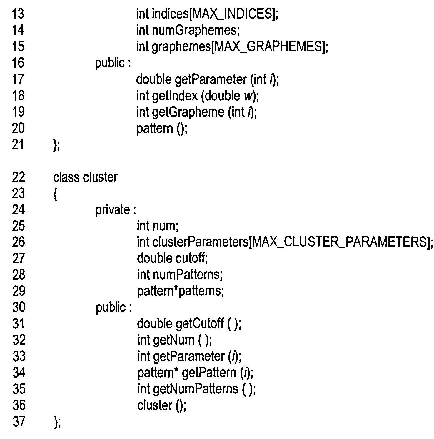
В строке 1 осуществляется объявление структуры данных «votes» 1802. Частичное объявление класса «parameter» представлено в строках 2-5. В данном примере единственно важным аспектом класса «parameter» является то, что базовый класс включает в себя виртуальную функцию-член «parameterize», которая в качестве входных данных принимает изображение символа, а возвращает значение признака с плавающей запятой. Конечно, в некоторых случаях конкретный признак может иметь только целые значения, а не значения с плавающей запятой. Структура данных «parameters» 1804 объявляется в строке 6. Частичное объявление класса «pattern» происходит в строках 7-21. Класс «pattern» включает в себя следующие private-компоненты: «patternNo» (1904 на рисунке 19А), объявленный в строке 10, массив значений признака «parameters» (1906 на рисунке 19А), объявленный в строке 11, количество индексов «numlndices» (1906 на рисунке 19А), объявленное в строке 12, набор индексов (1908 на рисунке 19А) элементов множества «numlndices», объявленный в строке 13, целочисленное значение «numGraphemes» (1910 на рисунке 19А), а также набор кодов графем «graphemes» (1912 на рисунке 19А) элементов множества «numGraphemes». Класс «pattern» включает функцию-член «getParameter», объявленную в строке 17, которая возвращает значение признака из набора значений «parameters», функцию-член «getlndex», объявленную в строке 18, которая возвращает индекс, соответствующий рассчитанному весу, а также функцию-член «getGrapheme», объявленную в строке 19, которая возвращает код графемы из набора кодов «graphemes», объявленного в строке 15. Наконец, в строках 22-37 объявляется класс «cluster», который представляет структуру данных кластера 1806 на рисунке 18. Класс «cluster» содержит следующие private - компоненты: num (1810 на рисунке 18), объявленный в строке 25, «clusterParameters» (1808 на рисунке 18), объявленный в строке 26, «cutoff» (1812 на рисунке 18), объявленный в строке 27, целочисленное значение «numPattems», указывающее на количество эталонов в кластере, объявленное в строке 28, а также указатель на эталоны в кластере «patterns», объявленный в строке 29. Класс «cluster» включает функции-члены «getCutoff» и «getNum», используемые для получения веса отсечки и количества эталонов, объявленные в строках 31 и 32, функцию-член «getParameter», используемую для получения индексов признаков из массива «clusterParameters», объявленную в строке 32, функцию-член «getPattem», возвращающую определенный эталон, хранящийся в кластере, объявленную в строке 33, и функцию-член «getNumPattems», объявленную в строке 34, которая возвращает количество эталонов, хранящееся в структуре данных кластера.
На примере следующего псевдокода функции «vote» показана реализация способа предварительной обработки для одного изображения символа и одного кластера:Using the following pseudo-code of the “vote” function as an example, an implementation of the preprocessing method for one symbol image and one cluster is shown:


Функция «vote» получает в качестве аргументов указатель на изображение символа и указатель на кластер. Локальные переменные включают в себя массив «params», объявленный в строке 38, в котором хранятся рассчитанные значения признаков для изображения символа, итерационные целочисленные значения i, j, k и l, объявленные в строке 39, переменные с плавающей запятой «weight» и «t», используемые для хранения рассчитанного веса, полученного в результате сравнения входного изображения символа и эталона из кластера, а также указатель р, объявленный в строке 41 и указывающий на эталон во входном кластере. В цикле for, в строках 43-44, значения всех признаков, используемых кластером, рассчитываются для входного изображения символа и записываются в массив «params» (1924 на рисунке 19Е). Затем во внешнем цикле for, содержащем вложенные циклы for, представленные в строках 45-58, рассматривается каждый признак входного кластера. В строке 46 получается указатель на рассматриваемый эталон путем вызова функции-члена кластера «getPattem». В строке 48 локальной переменной «weight» присваивается значение 0. Затем в цикле for, в строках 49-53, рассчитывается вес, который представляет собой сравнение входного изображения символа с эталоном, как описывалось выше со ссылкой на рисунок 19F. Когда вес превышает вес отсечки для кластера, как определено в строке 54, текущая итерация, выполняемая во внешнем цикле for, в строках 44-58, прерывается, поскольку входное изображение символа недостаточно похоже на рассматриваемый эталон, чтобы можно было за него проголосовать. В противном случае локальная переменная k принимает значение последнего индекса кода графемы для голосования в строке 55. Затем в цикле for, в строках 56-57, выполняется голосование за все графемы до графемы с индексом k.The vote function takes as arguments a pointer to a symbol image and a pointer to a cluster. Local variables include the “params” array declared in
Существует множество различных альтернативных подходов к осуществлению предварительной обработки и формированию описанных выше структур данных. Например, вместо использования веса отсечки для всего кластера можно использовать вес отсечки для конкретных эталонов, при этом вес отсечки может включаться в структуру данных эталона. В другом примере индексы, хранящиеся в эталоне, могут представлять собой экземпляры классов, которые содержат списки кодов графем, а не индексы, указывающие на упорядоченный список кодов графем, как это реализуется в последнем варианте осуществления. Также возможны и многие другие альтернативные варианты осуществления. Например, функция «vote» может принимать в качестве второго аргумента указатель на массив «params», а в цикле for, в строках 43-44, могут вычисляться значения признаков только в том случае, если они еще не были рассчитаны при обработке изображения символа для других кластеров. В других вариантах осуществления можно применять разные типы расчета веса и сравнения изображения символа с эталоном. В некоторых случаях большее значение веса может указывать на большее сходство изображения символа с эталоном в отличие от приведенного выше примера, когда увеличение значения веса означало уменьшение сходства изображения символа с эталоном. В ряде систем OCR с графемами могут связываться вещественные коэффициенты, позволяющие при голосовании использовать дробные значения и значения больше 1. В некоторых системах OCR графемы, эталоны и/или кластеры могут быть отсортированы на основании голосов, накопленных в течение предварительной обработки, для более эффективного последующего распознавания символов. В определенных вариантах осуществления структура данных кластера может включать в себя только количество структур данных эталона или ссылок на структуры данных эталона, при этом вес отсечки и эталоны, связанные с кластером, указываются в алгоритме управления, а не хранятся в структуре данных кластера.There are many different alternative approaches to performing preprocessing and generating the data structures described above. For example, instead of using the cutoff weight for the entire cluster, you can use the cutoff weight for specific standards, and the cutoff weight can be included in the data structure of the standard. In another example, the indexes stored in the template may be class instances that contain lists of grapheme codes, rather than indexes pointing to an ordered list of grapheme codes, as implemented in the latter embodiment. Many other alternative embodiments are also possible. For example, the “vote” function can take a pointer to the “params” array as the second argument, and in the for loop, lines 43-44, the values of the attributes can be calculated only if they have not yet been calculated when processing the symbol image for other clusters. In other embodiments, different types of weighting and comparing a symbol image with a reference can be used. In some cases, a higher weight value may indicate a greater similarity of the symbol image to the reference, in contrast to the above example, when an increase in the weight value meant a decrease in the similarity of the symbol image to the reference. In a number of OCR systems, material coefficients can be associated with graphemes, allowing fractional values and values greater than 1 to be used during voting. In some OCR systems, graphemes, standards, and / or clusters can be sorted based on votes accumulated during pre-processing for more efficient subsequent processing. character recognition. In certain embodiments, the cluster data structure may include only the number of reference data structures or references to the reference data structures, wherein the cutoff weights and the references associated with the cluster are indicated in the control algorithm rather than stored in the cluster data structure.
Как только, после предварительной обработки изображения символа при помощи эталонов, содержащихся в кластере, голоса в массиве (структуре данных) «votes» для конкретного изображения символа были, массив «votes» может быть в дальнейшем обработан, чтобы упорядочить список кодов графем, для которых получены голоса, в порядке убывания количества голосов. Можно считать, что количество голосов, накопленных для конкретной графемы, представляет собой рассчитанную степень сходства данной графемы с анализируемым изображением символа. В другом варианте реализации метода в качестве степени сходства может использоваться какая-либо другая метрика, рассчитанная по накопленному для данной графемы количеству голосов. Вышеупомянутый упорядоченный список открывают графемы, имеющие наибольшую степень сходства с анализируемым изображением символа, за ними следуют графемы с меньшей степенью сходства, и так далее, в порядке убывания степени сходства. В ином варианте реализации метода, описанный массив голосов может использоваться, чтобы накопить голоса, полученные в ходе предварительной обработки изображения символа при использовании не одного, а множества кластеров, после чего список графем может быть упорядочен аналогичным образом. В других вариантах реализации метода голоса могут одновременно накапливаться для двух или более изображений символов. Другими словами, есть много возможных способов накопления голосов в массиве «votes», и есть много способов использования накопленных голосов для получения различных результатов, таких как упорядоченный по убыванию степени сходства список графем.As soon as, after preliminary processing of the symbol image using the standards contained in the cluster, there were voices in the “votes” array (data structure) for a particular symbol image, the votes array can be further processed to sort the list of grapheme codes for which votes received, in decreasing order of the number of votes. We can assume that the number of votes accumulated for a particular grapheme represents the calculated degree of similarity of a given grapheme with the analyzed symbol image. In another embodiment of the method, some other metric calculated from the number of votes accumulated for a given grapheme can be used as the degree of similarity. The aforementioned ordered list is opened by graphemes that have the greatest degree of similarity with the symbol image being analyzed, followed by graphemes with a lower degree of similarity, and so on, in decreasing order of degree of similarity. In another embodiment of the method, the described array of votes can be used to accumulate the votes obtained during the preliminary processing of the symbol image when using not one, but many clusters, after which the list of graphemes can be ordered in a similar way. In other implementations of the voice method, they can simultaneously accumulate for two or more symbol images. In other words, there are many possible ways to accumulate votes in the “votes” array, and there are many ways to use accumulated votes to get different results, such as a list of graphemes arranged in descending order of similarity.
Хотя настоящее изобретение описывается на примере конкретных вариантов осуществления, предполагается, что оно не будет ограничено только этими вариантами осуществления. Специалистам в данной области будут очевидны возможные модификации сущности настоящего изобретения. Например, любой из множества возможных вариантов осуществления структур данных и методов, используемых для предварительной обработки в соответствии с обобщенным третьим вариантом осуществления системы OCR, описанным выше, может быть достигнут путем изменения любого из различных параметров проектирования и реализации, среди которых: структуры данных, структуры управления, модульное исполнение, язык программирования, используемая операционная система и аппаратное обеспечение, а также многие другие подобные параметры проектирования и реализации.Although the present invention is described by the example of specific embodiments, it is contemplated that it will not be limited only to these embodiments. Possible modifications to the spirit of the present invention will be apparent to those skilled in the art. For example, any of the many possible embodiments of the data structures and methods used for pre-processing in accordance with the generalized third embodiment of the OCR system described above can be achieved by changing any of the various design and implementation parameters, including: data structures, structures control, modular execution, programming language, the operating system and hardware used, as well as many other similar design parameters and implementations.
Следует понимать, что представленное выше описание раскрытых вариантов осуществления предоставлено для того, чтобы дать возможность любому специалисту в данной области повторить или применить настоящее изобретение. Специалистам в данной области будут очевидны возможные модификации представленных вариантов осуществления, при этом общие принципы, представленные здесь, могут применяться к другим вариантам осуществления без отступления от сущности или объема описания. Таким образом, настоящее описание не ограничено представленными здесь вариантами осуществления, оно соответствует широкому кругу задач, связанных с принципами и новыми отличительными признаками, раскрытыми в настоящем документе.It should be understood that the above description of the disclosed embodiments is provided to enable any person skilled in the art to repeat or apply the present invention. Possible modifications to the presented embodiments will be apparent to those skilled in the art, while the general principles presented here can be applied to other embodiments without departing from the spirit or scope of the description. Thus, the present description is not limited to the embodiments presented here, it corresponds to a wide range of tasks related to the principles and new features disclosed herein.
Claims (77)
Priority Applications (2)
| Application Number | Priority Date | Filing Date | Title |
|---|---|---|---|
| RU2014103152A RU2640322C2 (en) | 2014-01-30 | 2014-01-30 | Methods and systems of effective automatic recognition of symbols |
| US14/508,492 US9892114B2 (en) | 2014-01-30 | 2014-10-07 | Methods and systems for efficient automated symbol recognition |
Applications Claiming Priority (1)
| Application Number | Priority Date | Filing Date | Title |
|---|---|---|---|
| RU2014103152A RU2640322C2 (en) | 2014-01-30 | 2014-01-30 | Methods and systems of effective automatic recognition of symbols |
Publications (2)
| Publication Number | Publication Date |
|---|---|
| RU2014103152A RU2014103152A (en) | 2015-08-10 |
| RU2640322C2 true RU2640322C2 (en) | 2017-12-27 |
Family
ID=53679369
Family Applications (1)
| Application Number | Title | Priority Date | Filing Date |
|---|---|---|---|
| RU2014103152A RU2640322C2 (en) | 2014-01-30 | 2014-01-30 | Methods and systems of effective automatic recognition of symbols |
Country Status (2)
| Country | Link |
|---|---|
| US (1) | US9892114B2 (en) |
| RU (1) | RU2640322C2 (en) |
Families Citing this family (8)
| Publication number | Priority date | Publication date | Assignee | Title |
|---|---|---|---|---|
| US9911034B2 (en) * | 2013-06-18 | 2018-03-06 | Abbyy Development Llc | Methods and systems that use hierarchically organized data structure containing standard feature symbols in order to convert document images to electronic documents |
| CN105631393A (en) * | 2014-11-06 | 2016-06-01 | 阿里巴巴集团控股有限公司 | Information recognition method and device |
| US9569710B1 (en) * | 2015-12-14 | 2017-02-14 | International Business Machines Corporation | Encoding and decoding data in two-dimensional symbology |
| RU2652461C1 (en) | 2017-05-30 | 2018-04-26 | Общество с ограниченной ответственностью "Аби Девелопмент" | Differential classification with multiple neural networks |
| US11328167B2 (en) | 2017-07-21 | 2022-05-10 | Hewlett-Packard Development Compant, L.P. | Optical character recognitions via consensus of datasets |
| RU2673015C1 (en) * | 2017-12-22 | 2018-11-21 | Общество с ограниченной ответственностью "Аби Продакшн" | Methods and systems of optical recognition of image series characters |
| KR20210054932A (en) * | 2019-11-06 | 2021-05-14 | 삼성전자주식회사 | Electronic device and method for controlling the same, and storage medium |
| KR20230009742A (en) * | 2021-07-09 | 2023-01-17 | 휴렛-팩커드 디벨롭먼트 컴퍼니, 엘.피. | Edit of text layer and image layer in document including handwritten text |
Citations (5)
| Publication number | Priority date | Publication date | Assignee | Title |
|---|---|---|---|---|
| RU2113726C1 (en) * | 1996-08-16 | 1998-06-20 | Акционерное общество закрытого типа Научно-производственное предприятие - центр "Реабилитация" | Computer equipment for reading of printed text |
| EA200401629A1 (en) * | 2002-05-31 | 2005-06-30 | Эли Абир | METHOD AND DEVICE OF ASSOCIATION OF WORDS |
| US20070065013A1 (en) * | 2002-01-25 | 2007-03-22 | Xerox Corporation | Method and apparatus to convert digital ink images for use in a structured text/graphics editor |
| US7242805B1 (en) * | 2003-04-18 | 2007-07-10 | Kamran Reihani | System and method for automated symbolic recognition including database modeling |
| US20090208144A1 (en) * | 2007-04-22 | 2009-08-20 | Bo-In Lin | User control of computer peripheral apparatuses to perform tasks according to user input image file |
Family Cites Families (49)
| Publication number | Priority date | Publication date | Assignee | Title |
|---|---|---|---|---|
| US5031225A (en) | 1987-12-09 | 1991-07-09 | Ricoh Company, Ltd. | Character recognition method for recognizing character in an arbitrary rotation position |
| US5625710A (en) * | 1988-07-20 | 1997-04-29 | Fujitsu Limited | Character recognition apparatus using modification of a characteristic quantity |
| US4950167A (en) | 1989-10-19 | 1990-08-21 | Jewish Employment And Vocational Service | Visual detail perception test kit and methods of use |
| JPH04195485A (en) | 1990-11-28 | 1992-07-15 | Hitachi Ltd | Image information input device |
| US5425110A (en) | 1993-04-19 | 1995-06-13 | Xerox Corporation | Method and apparatus for automatic language determination of Asian language documents |
| US5710916A (en) * | 1994-05-24 | 1998-01-20 | Panasonic Technologies, Inc. | Method and apparatus for similarity matching of handwritten data objects |
| JP3727971B2 (en) | 1995-02-01 | 2005-12-21 | キヤノン株式会社 | Document processing apparatus and document processing method |
| BR9609099A (en) | 1995-06-07 | 1999-02-02 | Elcor Corp | Process and device for separating a gas stream |
| US6041137A (en) * | 1995-08-25 | 2000-03-21 | Microsoft Corporation | Radical definition and dictionary creation for a handwriting recognition system |
| US6076051A (en) | 1997-03-07 | 2000-06-13 | Microsoft Corporation | Information retrieval utilizing semantic representation of text |
| US6005986A (en) | 1997-12-03 | 1999-12-21 | The United States Of America As Represented By The National Security Agency | Method of identifying the script of a document irrespective of orientation |
| US6804414B1 (en) | 1998-05-01 | 2004-10-12 | Fujitsu Limited | Image status detecting apparatus and document image correcting apparatus |
| US6389166B1 (en) | 1998-10-26 | 2002-05-14 | Matsushita Electric Industrial Co., Ltd. | On-line handwritten Chinese character recognition apparatus |
| US6208968B1 (en) * | 1998-12-16 | 2001-03-27 | Compaq Computer Corporation | Computer method and apparatus for text-to-speech synthesizer dictionary reduction |
| US6512522B1 (en) | 1999-04-15 | 2003-01-28 | Avid Technology, Inc. | Animation of three-dimensional characters along a path for motion video sequences |
| JP3678941B2 (en) * | 1999-05-28 | 2005-08-03 | シャープ株式会社 | Image processing apparatus and image forming apparatus having the same |
| US6657625B1 (en) | 1999-06-09 | 2003-12-02 | Microsoft Corporation | System and method of caching glyphs for display by a remote terminal |
| JP2001043310A (en) | 1999-07-30 | 2001-02-16 | Fujitsu Ltd | Device and method for correcting document picture |
| US6661417B1 (en) | 2000-08-28 | 2003-12-09 | Dynalab Inc. | System and method for converting an outline font into a glyph-based font |
| US7254269B2 (en) | 2000-08-31 | 2007-08-07 | Hewlett-Packard Development Company, L.P. | Character recognition system |
| US7082219B2 (en) * | 2002-02-04 | 2006-07-25 | The United States Of America As Represented By The Secretary Of The Air Force | Method and apparatus for separating text from images |
| FR2836573A1 (en) * | 2002-02-27 | 2003-08-29 | France Telecom | Computer representation of a data tree structure, which is representative of the organization of a data set or data dictionary, has first and second total order relations representative of tree nodes and stored data items |
| US20070094166A1 (en) * | 2002-08-05 | 2007-04-26 | Edwin Addison | Knowledge-based methods for genetic network analysis and the whole cell computer system based thereon |
| US7027054B1 (en) | 2002-08-14 | 2006-04-11 | Avaworks, Incorporated | Do-it-yourself photo realistic talking head creation system and method |
| US7106905B2 (en) | 2002-08-23 | 2006-09-12 | Hewlett-Packard Development Company, L.P. | Systems and methods for processing text-based electronic documents |
| US7362901B2 (en) * | 2003-09-05 | 2008-04-22 | Gannon Technology Holdings Llc | Systems and methods for biometric identification using handwriting recognition |
| US7454067B1 (en) * | 2003-09-12 | 2008-11-18 | Adobe Systems Incorporated | Symbol classification depending on cluster shapes in difference image |
| US8732025B2 (en) * | 2005-05-09 | 2014-05-20 | Google Inc. | System and method for enabling image recognition and searching of remote content on display |
| US8326037B1 (en) * | 2005-11-23 | 2012-12-04 | Matrox Electronic Systems, Ltd. | Methods and apparatus for locating an object in an image |
| TWI332635B (en) | 2007-01-05 | 2010-11-01 | Compal Electronics Inc | Method for determing oriention of chinese words |
| US7805004B2 (en) | 2007-02-28 | 2010-09-28 | Microsoft Corporation | Radical set determination for HMM based east asian character recognition |
| US8351707B2 (en) * | 2007-07-31 | 2013-01-08 | Sharp Kabushiki Kaisha | Image processing apparatus, image forming apparatus, image processing system, and image processing method |
| JP5666307B2 (en) * | 2007-11-26 | 2015-02-12 | ウォーレン・ダニエル・チャイルドWarren Daniel CHILD | System and method for classification and reading of Kanji characters and character components |
| US8027539B2 (en) | 2008-01-11 | 2011-09-27 | Sharp Laboratories Of America, Inc. | Method and apparatus for determining an orientation of a document including Korean characters |
| CN102084363B (en) * | 2008-07-03 | 2014-11-12 | 加利福尼亚大学董事会 | A method for efficiently supporting interactive, fuzzy search on structured data |
| JP2011118694A (en) * | 2009-12-03 | 2011-06-16 | Sony Corp | Learning device and method, recognition device and method, and program |
| US9213687B2 (en) * | 2009-03-23 | 2015-12-15 | Lawrence Au | Compassion, variety and cohesion for methods of text analytics, writing, search, user interfaces |
| US20110043528A1 (en) | 2009-08-24 | 2011-02-24 | Apple Inc. | Cache management for glyph display |
| JP5363591B2 (en) * | 2009-12-15 | 2013-12-11 | 富士通フロンテック株式会社 | Character recognition method, character recognition device, and character recognition program |
| JP2012009000A (en) * | 2010-05-24 | 2012-01-12 | Pfu Ltd | Business form processing system, ocr device, ocr processing program, business form creation device, business form creation program, and business form processing method |
| CN102402693B (en) | 2010-09-09 | 2014-07-30 | 富士通株式会社 | Method and equipment for processing images containing characters |
| US8856127B2 (en) * | 2010-10-14 | 2014-10-07 | 6464076 Canada Inc. | Method of visualizing the collective opinion of a group |
| US8953888B2 (en) * | 2011-02-10 | 2015-02-10 | Microsoft Corporation | Detecting and localizing multiple objects in images using probabilistic inference |
| US8494276B2 (en) * | 2011-09-23 | 2013-07-23 | International Business Machines Corporation | Tactile input recognition using best fit match |
| US20130322759A1 (en) * | 2011-12-01 | 2013-12-05 | Peking University Founder Group Co., Ltd. | Method and device for identifying font |
| US20150139559A1 (en) * | 2012-09-14 | 2015-05-21 | Google Inc. | System and method for shape clustering using hierarchical character classifiers |
| US9710462B2 (en) * | 2013-01-29 | 2017-07-18 | Learning Sites, Inc. | System and method for automatically translating an imaged surface of an object |
| US9665246B2 (en) * | 2013-04-16 | 2017-05-30 | Google Inc. | Consistent text suggestion output |
| US9589185B2 (en) * | 2014-12-10 | 2017-03-07 | Abbyy Development Llc | Symbol recognition using decision forests |
-
2014
- 2014-01-30 RU RU2014103152A patent/RU2640322C2/en active
- 2014-10-07 US US14/508,492 patent/US9892114B2/en not_active Expired - Fee Related
Patent Citations (5)
| Publication number | Priority date | Publication date | Assignee | Title |
|---|---|---|---|---|
| RU2113726C1 (en) * | 1996-08-16 | 1998-06-20 | Акционерное общество закрытого типа Научно-производственное предприятие - центр "Реабилитация" | Computer equipment for reading of printed text |
| US20070065013A1 (en) * | 2002-01-25 | 2007-03-22 | Xerox Corporation | Method and apparatus to convert digital ink images for use in a structured text/graphics editor |
| EA200401629A1 (en) * | 2002-05-31 | 2005-06-30 | Эли Абир | METHOD AND DEVICE OF ASSOCIATION OF WORDS |
| US7242805B1 (en) * | 2003-04-18 | 2007-07-10 | Kamran Reihani | System and method for automated symbolic recognition including database modeling |
| US20090208144A1 (en) * | 2007-04-22 | 2009-08-20 | Bo-In Lin | User control of computer peripheral apparatuses to perform tasks according to user input image file |
Also Published As
| Publication number | Publication date |
|---|---|
| US20150213330A1 (en) | 2015-07-30 |
| RU2014103152A (en) | 2015-08-10 |
| US9892114B2 (en) | 2018-02-13 |
Similar Documents
| Publication | Publication Date | Title |
|---|---|---|
| RU2640322C2 (en) | Methods and systems of effective automatic recognition of symbols | |
| RU2648638C2 (en) | Methods and systems of effective automatic recognition of symbols using a multiple clusters of symbol standards | |
| RU2598300C2 (en) | Methods and systems for automatic recognition of characters using forest solutions | |
| RU2631168C2 (en) | Methods and devices that convert images of documents to electronic documents using trie-data structures containing unparameterized symbols for definition of word and morphemes on document image | |
| US10339378B2 (en) | Method and apparatus for finding differences in documents | |
| CN110942074B (en) | Character segmentation recognition method and device, electronic equipment and storage medium | |
| WO2021017260A1 (en) | Multi-language text recognition method and apparatus, computer device, and storage medium | |
| RU2643465C2 (en) | Devices and methods using a hierarchially ordered data structure containing unparametric symbols for converting document images to electronic documents | |
| US7653244B2 (en) | Intelligent importation of information from foreign applications user interface | |
| US9589185B2 (en) | Symbol recognition using decision forests | |
| RU2571616C1 (en) | Optical character recognition system and method, reducing processing time for images potentially not containing characters | |
| CN112613502A (en) | Character recognition method and device, storage medium and computer equipment | |
| US20140169678A1 (en) | Method and system for text-image orientation | |
| CN114005123A (en) | System and method for digitally reconstructing layout of print form text | |
| RU2625533C1 (en) | Devices and methods, which build the hierarchially ordinary data structure, containing nonparameterized symbols for documents images conversion to electronic documents | |
| RU2626656C2 (en) | Method and system of determining orientation of text image | |
| RU2597163C2 (en) | Comparing documents using reliable source | |
| RU2582064C1 (en) | Methods and systems for effective automatic recognition of symbols using forest solutions | |
| RU2625020C1 (en) | Devices and methods, which prepare parametered symbols for transforming images of documents into electronic documents | |
| Jia et al. | Grayscale-projection based optimal character segmentation for camera-captured faint text recognition | |
| JPH0333990A (en) | Optical character recognition instrument and method using mask processing | |
| CN116563869B (en) | Page image word processing method and device, terminal equipment and readable storage medium | |
| CN114220109A (en) | Character definition conversion method, system, terminal and medium based on OCR technology | |
| CN115100672A (en) | Character detection and identification method, device and equipment and computer readable storage medium | |
| TAKAHASHI et al. | A hybrid recognition algorithm with learning capability and its application to an OCR system |
Legal Events
| Date | Code | Title | Description |
|---|---|---|---|
| PC43 | Official registration of the transfer of the exclusive right without contract for inventions |
Effective date: 20181121 |
|
| QB4A | Licence on use of patent |
Free format text: LICENCE FORMERLY AGREED ON 20201211 Effective date: 20201211 |
|
| QC41 | Official registration of the termination of the licence agreement or other agreements on the disposal of an exclusive right |
Free format text: LICENCE FORMERLY AGREED ON 20201211 Effective date: 20220311 |