RU2639058C2 - Nasal filter - Google Patents
Nasal filter Download PDFInfo
- Publication number
- RU2639058C2 RU2639058C2 RU2015116596A RU2015116596A RU2639058C2 RU 2639058 C2 RU2639058 C2 RU 2639058C2 RU 2015116596 A RU2015116596 A RU 2015116596A RU 2015116596 A RU2015116596 A RU 2015116596A RU 2639058 C2 RU2639058 C2 RU 2639058C2
- Authority
- RU
- Russia
- Prior art keywords
- lateral
- filter
- nose
- medial
- support section
- Prior art date
Links
Images
Classifications
-
- A—HUMAN NECESSITIES
- A62—LIFE-SAVING; FIRE-FIGHTING
- A62B—DEVICES, APPARATUS OR METHODS FOR LIFE-SAVING
- A62B23/00—Filters for breathing-protection purposes
- A62B23/06—Nose filters
-
- A—HUMAN NECESSITIES
- A62—LIFE-SAVING; FIRE-FIGHTING
- A62B—DEVICES, APPARATUS OR METHODS FOR LIFE-SAVING
- A62B7/00—Respiratory apparatus
- A62B7/10—Respiratory apparatus with filter elements
Abstract
Description
Область техникиTechnical field
Настоящее изобретение относится к назальным фильтрам с каркасом, к которому присоединяется фильтр, например плоский фильтр. В частности, оно относится к назальному фильтру, содержащему каркас с правым и левым участками каркаса, размер которых позволяет разместить их внутри правой и левой ноздри, например, соединенных посредством U-образной перемычки.The present invention relates to nasal filters with a scaffold to which a filter is attached, for example a flat filter. In particular, it relates to a nasal filter containing a scaffold with right and left scaffold sections, the size of which allows them to be placed inside the right and left nostrils, for example, connected by a U-shaped jumper.
Уровень техникиState of the art
Фильтрация вдыхаемого воздуха является одной из основных функций передней носовой полости и верхних дыхательных путей человека. Естественный механизм фильтрации функционирует в качестве средства защиты от частиц, осаждающихся в нижних дыхательных путях или, в конечном итоге, в бронхах.Filtration of inhaled air is one of the main functions of the anterior nasal cavity and upper respiratory tract of a person. The natural filtration mechanism functions as a means of protection against particles deposited in the lower respiratory tract or, ultimately, in the bronchi.
Однако естественная фильтрация частиц, особенно, когда частицы размером более 10 микрон осаждаются на мембрану слизистой оболочки носа, для некоторых людей может быть чрезвычайно вредна, поскольку у них развивается аллергическая реакция на эти частицы. Чтобы защитить человека от нежелательных частиц при дыхании, разработано множество фильтров, выбор которых описан далее.However, the natural filtration of particles, especially when particles larger than 10 microns are deposited on the membrane of the nasal mucosa, can be extremely harmful for some people because they develop an allergic reaction to these particles. To protect a person from unwanted particles during breathing, many filters have been developed, the selection of which is described below.
В отношении терминологии следует отметить, что вертикальная центральная стенка носа между левой и правой ноздрями обычно называется срединной стенкой или перегородкой носа и оканчивается у нижнего конца носа, который называется колумеллой. Ноздри в основном ограничены перегородкой и латеральными частями, которые представляют собой крылья ноздрей наружного носа, изгибающиеся от края перегородки у кончика носа до заднего края перегородки около черепа. Направление вперед к кончику носа называется передним, а от спинки носа к черепу - задним.In terms of terminology, it should be noted that the vertical central wall of the nose between the left and right nostrils is usually called the median wall or septum of the nose and ends at the lower end of the nose, which is called columella. The nostrils are mainly limited by the septum and the lateral parts, which are the wings of the nostrils of the external nose, curving from the edge of the septum at the tip of the nose to the posterior edge of the septum near the skull. The direction forward to the tip of the nose is called the front, and from the back of the nose to the skull - the back.
Персональные устройства фильтрации воздуха могут быть поделены на две основные категории: лицевые маски, которые закрывают и рот, и нос, и назальные фильтры, которые закрывают только нос. Назальные фильтры могут подразделяться на размещаемые снаружи назальные фильтры и размещаемые внутри назальные фильтры.Personal air filtration devices can be divided into two main categories: face masks that cover both the mouth and nose, and nasal filters that cover only the nose. Nasal filters can be divided into nasal filters placed on the outside and nasal filters placed on the inside.
Многие назальные фильтры обладают одним фильтрующим элементом для каждой ноздри, фильтрующие элементы соединены посредством U-образной гибкой перемычки, которая зажимается вокруг колумеллы носа и удерживает фильтрующие элементы на месте внутри ноздрей. Фильтрующие элементы часто являются вытянутыми c продольным направлением и поперечным направлением; когда они вставлены в нос, продольное направление фильтра продолжается от передней части ноздри у кончика носа до задней части ноздри около черепа, и поперечное направление продолжается от перегородки носа до латеральной части носа.Many nasal filters have one filter element for each nostril, and the filter elements are connected by a U-shaped flexible jumper, which is clamped around the columella of the nose and holds the filter elements in place inside the nostrils. The filter elements are often elongated with a longitudinal direction and a transverse direction; when inserted into the nose, the longitudinal direction of the filter continues from the front of the nostril at the tip of the nose to the back of the nostril near the skull, and the transverse direction continues from the septum of the nose to the lateral part of the nose.
Существующие назальные фильтры с размещением внутри в основном могут быть отнесены к категориям конусообразных устройств и плоских фильтрующих устройств. Преимуществами первых считается их гибкость, устойчивое позиционирование, большая площадь поверхности для фильтрации и уровень комфорта, например, как указано в патентной публикации US или публикациях заявок на патенты US 2055855, US 7748383, US 2007/0193233 и US 2005/0205095. Преимуществами последних считается их малый размер, возможность визуального контроля, способность внедряться и повышенный комфорт при использовании.Existing nasal filters with interior placement can generally be categorized as cone-shaped devices and flat filter devices. The advantages of the former are considered to be their flexibility, stable positioning, a large surface area for filtration and a level of comfort, for example, as indicated in the US patent publication or the publication of patent applications US 2055855, US 7748383, US 2007/0193233 and US 2005/0205095. The advantages of the latter are their small size, the ability to visually control, the ability to infiltrate and increased comfort when using.
По существу устройства с плоским типом фильтра предлагаются в публикациях заявки на патент Канады СА 26589940, заявки на патент Великобритании GB 2289846, документе изложенного патента Германии DE 3914606 A1, заявки на патент Японии JP2002-345986A, полезной модели Германии DE 202010001203 U1, патентных публикациях US и публикациях заявок на патенты US 2046664, US 228268, US 5392773, US 7156099, US 2007/0283963, US 2008/0087286, US 2012/0111334 и заявок на международные патенты WO 2005/120645, WO 2009/097553 и WO 2011/041921.Essentially, devices with a flat filter type are proposed in publications of Canadian patent application CA 26589940, UK patent application GB 2289846, German patent document DE 3914606 A1, Japanese patent application JP2002-345986A, German utility model DE 202010001203 U1, US patent publications and the publication of patent applications US 2046664, US 228268, US 5392773, US 7156099, US 2007/0283963, US 2008/0087286, US 2012/0111334 and international patent applications WO 2005/120645, WO 2009/097553 and WO 2011/041921 .
Для надежного использования внутреннего назального фильтра, приемлемого и привлекательного для пользователя в повседневной жизни, он должен удовлетворять основным целям: он должен быть почти невидимым, он должен обеспечивать соответствующее движение воздуха без резкого увеличения сопротивления при дыхании, он должен выниматься при удалении зажимного средства, он должен обладать способностью вмещения в носы разного размера и формы, он должен по существу повторять кривизну носовой полости, чтобы весь вдыхаемый воздух проходил через фильтрующее устройство, и, наконец, он должен быть удобным при использовании.In order to reliably use an internal nasal filter that is acceptable and attractive to the user in everyday life, it must meet the main goals: it must be almost invisible, it must provide adequate air movement without a sharp increase in breathing resistance, it must be removed when the clamping means are removed, it must have the ability to accommodate noses of different sizes and shapes, it must essentially repeat the curvature of the nasal cavity so that all inhaled air passes through the phi a bleeding device, and finally, it should be convenient to use.
Основным недостатком конусообразных структур является в основном напластованная масса материала, который должен быть помещен в носовую полость. Это повышает возможность визуального контроля фильтра; уменьшает доступное пространство для воздушного потока, таким образом, повышая сопротивление; и создает ощущение дискомфорта у пользователей, таким образом, снижая соответствие.The main disadvantage of cone-shaped structures is mainly the bedded mass of material that must be placed in the nasal cavity. This increases the ability to visually control the filter; reduces the available space for air flow, thereby increasing resistance; and creates a feeling of discomfort for users, thereby reducing compliance.
Основным недостатком плоских назальных фильтров в основном является недостаток их гибкости и адаптации, их тенденция к неустойчивому движению при движениях носа и дыхании, что оставляет места утечки для вдыхаемого воздуха и их поперечное позиционирование в полости, что приводит к болям, особенно при прикосновении к носу.The main disadvantage of flat nasal filters is mainly the lack of flexibility and adaptation, their tendency to unstable movement during movements of the nose and breathing, which leaves a leak for breathing air and their lateral positioning in the cavity, which leads to pain, especially when touching the nose.
И конусообразные назальные фильтры, и плоские фильтры изготавливают в виде однокомпонентного и двухкомпонентного решений, в которых основным доводом для введения большего числа компонентом была идея наличия взаимозаменяемых частей. Самым главным недостатком этих систем является повышенное сопротивление потоку воздуха, которое возникает из-за того, что материал занимает слишком много места в носовой полости.Both cone-shaped nasal filters and flat filters are made in the form of one-component and two-component solutions, in which the main argument for introducing a larger number of components was the idea of having interchangeable parts. The main drawback of these systems is the increased resistance to air flow, which occurs due to the fact that the material takes up too much space in the nasal cavity.
Все упомянутые выше общие недостатки приводят к более низкой приспособляемости среди потенциальных пользователей, чем следовало бы ожидать, если достигнуты все основные цели.All of the common weaknesses mentioned above lead to lower adaptability among potential users than would be expected if all the main goals were achieved.
В европейском патенте EP 2089115 В1 предлагается внутренний назальный фильтр, содержащий фильтрующие компоненты в форме вогнуто-выгнутого стекла на овальной опоре, которая присоединена к гибкой U-образной перемычке, функционирующей в качестве зажима вокруг нижнего края хряща носа. Концы гибкого U-образного элемента (далее называемые огибающими) размещены по существу перпендикулярно гибкому U-образному элементу. Это приводит к тому, что огибающие и фильтр перпендикулярны потоку воздуха, что имеет смысл с точки зрения перспективы фильтрации. Однако это также приводит к увеличению сопротивления, поскольку огибающие размещены в основном потоке воздуха, что затрудняет дыхание. Кроме того, угол, под которым размещены огибающие и их твердость приводят к дискомфорту при прикосновении или движении носа. Хотя в публикации EP 2089115 В1 применена идея использования более гибких фильтрующих компонентов для регулировки для разного размера и формы носа, варианты осуществления огибающих не обладают способностью удерживать фильтрующий компонент без внутренней жесткости. Это приводит к дискомфорту из-за необходимых характеристик структурной жесткости фильтрующих компонентов и их расположения под углом, перпендикулярным носовому каналу. Это также приводит к зазорам вдоль изгиба носовой полости, через которые вдыхается неотфильтрованный воздух.EP 2089115 B1 proposes an internal nasal filter containing concave-curved glass filter components on an oval support that is attached to a flexible U-shaped jumper that functions as a clamp around the lower edge of the nose cartilage. The ends of the flexible U-shaped member (hereinafter referred to as envelopes) are arranged substantially perpendicular to the flexible U-shaped member. This leads to the fact that the envelopes and the filter are perpendicular to the air flow, which makes sense from the point of view of the filtration perspective. However, this also leads to an increase in resistance, since envelopes are located in the main air stream, which makes breathing difficult. In addition, the angle at which the envelopes are placed and their hardness leads to discomfort when touching or moving the nose. Although EP 2089115 B1 uses the idea of using more flexible filter components to adjust for different nose sizes and shapes, envelope embodiments do not have the ability to hold the filter component without internal stiffness. This leads to discomfort due to the necessary characteristics of the structural rigidity of the filter components and their location at an angle perpendicular to the nasal canal. This also leads to gaps along the bend of the nasal cavity through which unfiltered air is inhaled.
Следовательно, в этой области техники необходимо улучшение.Therefore, improvement is needed in this technical field.
Сущность изобретенияSUMMARY OF THE INVENTION
Целью настоящего изобретения является достижение упомянутых выше целей и преодоление общих недостатков предшествующего уровня техники, в частности конусообразных и плоских фильтров, а также специфических недостатков, упомянутых выше. В частности, целью настоящего изобретение является обеспечение назального фильтра, который эффективен и удобен при использовании.The aim of the present invention is to achieve the above objectives and to overcome the common disadvantages of the prior art, in particular cone-shaped and flat filters, as well as the specific disadvantages mentioned above. In particular, it is an object of the present invention to provide a nasal filter that is effective and convenient to use.
Эта цель достигается посредством назального фильтра в соответствии со следующим.This goal is achieved through a nasal filter in accordance with the following.
Назальный фильтр содержит каркас с правым и левым участками каркаса, размер которых позволяет разместить их внутри правой и левой ноздри, соответственно. Каждый участок каркаса содержит переднюю опорную секцию, выполненную таким образом, чтобы она была направлена к передней части носа, когда назальный фильтр вводится в нос. Кроме того, каждый участок каркаса содержит заднюю опорную секцию, выполненную таким образом, чтобы она была направлена к спинке носа, когда назальный фильтр вводится в нос. Передняя опорная секция и задняя опорная секция поддерживают фильтрующий элемент, например по существу плоский фильтрующий элемент.The nasal filter contains a carcass with right and left parts of the carcass, the size of which allows you to place them inside the right and left nostrils, respectively. Each section of the carcass contains a front support section, designed so that it is directed to the front of the nose when the nasal filter is inserted into the nose. In addition, each section of the carcass contains a back support section, designed so that it is directed to the back of the nose when the nasal filter is inserted into the nose. The front support section and the rear support section support a filter element, for example a substantially flat filter element.
Каждый участок каркаса содержит упругое средство, соединяющее переднюю опорную секцию с задней опорной секцией для гибкого изменения расстояния между передней опорной секцией и задней опорной секцией.Each frame section contains elastic means connecting the front support section to the rear support section to flexibly change the distance between the front support section and the rear support section.
Далее термин "состояние без напряжения" используется для указания того, что описанная форма присуща назальному фильтру, и это означает, что фильтр принимает эту форму, когда на него не действуют усилия, вызывающие деформацию фильтра. Например, подразумевается, что изгиб, как часть назального фильтра, существует без деформации под действием на фильтр с усилием. Подразумевается, что все описанные далее формы являются присущими свойствами фильтра.Further, the term “stress-free state” is used to indicate that the described shape is inherent in the nasal filter, and this means that the filter takes on this shape when it is not affected by forces causing the filter to deform. For example, it is understood that bending, as part of a nasal filter, exists without deformation by force on the filter. It is understood that all of the forms described below are inherent properties of the filter.
Например, в противоположность указанному в упомянутой выше публикации GB 2289846, где круглый каркас вокруг фильтрующего элемента деформируется приложением ручного усилия и принимает форму сердца с изгибом между противоположными секциями круглого каркаса.For example, in contrast to GB 2289846 indicated in the aforementioned publication, where the round frame around the filter element is deformed by applying manual force and takes the shape of a heart with a bend between opposite sections of the round frame.
Также далее будут использованы термины "вверх" и "вниз", несмотря на тот факт, что назальный фильтр, в принципе, может обладать любой ориентацией до и даже после введения в нос. Однако, тем не менее, кажется оправданным и приемлемым для простоты использовать термины "вверх" или "вниз" общепринятым образом. Термин "вниз" и "ниже фильтрующего элемента" будет использован при направлениях от фильтрующего элемента и к той части назального фильтра, которая ближе к колумелле, в то время как термин "вверх" и "над фильтрующим элементом" будет использоваться для противоположного направления.Also, the terms “up” and “down” will be used below, despite the fact that the nasal filter, in principle, can have any orientation before and even after insertion into the nose. However, however, it seems reasonable and acceptable for simplicity to use the terms “up” or “down” in a generally accepted manner. The term "down" and "below the filter element" will be used in directions from the filter element and to that part of the nasal filter that is closer to the columella, while the terms "up" and "above the filter element" will be used for the opposite direction.
Термины "передний" или "задний" используются для тех частей, которые предназначены для размещения около передней или задней части ноздри. Термины "медиальный" и "латеральный" используются для тех частей назального фильтра, которые направлены к медиальной части или латеральной части носа, соответственно.The terms "front" or "back" are used for those parts that are designed to be placed near the front or back of the nostril. The terms “medial” and “lateral” are used for those parts of the nasal filter that are directed towards the medial or lateral part of the nose, respectively.
Термин "радиус кривизны" используется далее для вектора, который имеет начало в точке на кривой, обладает длиной, равной радиусу круга, описывающего изгиб кривой в этой точке, и направлен по такому радиусу в эту точку.The term "radius of curvature" is used hereinafter for a vector that has a beginning at a point on the curve, has a length equal to the radius of the circle describing the curve of the curve at this point, and is directed along this radius to this point.
Преимуществом такого назального фильтра является удобное и эффективное размещение и регулировка назального фильтра при введении в нос. Поскольку передняя и задняя опорные секции соединены упруго, участки каркаса могут легко сокращаться и приспосабливаться, например, посредством дополнительного бокового упругого перемещения и скручивания при введении в нос, что предпочтительно для прилегания и комфорта пользователя. Кроме того, при создании назального фильтра из гибкого полимерного материала, например силикона или термопластичного эластомера, каркас удобно прилегает к носам разного размера и формы.The advantage of such a nasal filter is the convenient and efficient placement and adjustment of the nasal filter when inserted into the nose. Since the front and rear support sections are connected elastically, sections of the frame can be easily contracted and adapted, for example, by additional lateral elastic movement and twisting when introduced into the nose, which is preferable for the fit and comfort of the user. In addition, when creating a nasal filter from a flexible polymeric material, such as silicone or a thermoplastic elastomer, the frame fits snugly to noses of different sizes and shapes.
Необязательно два участка каркаса соединены гибкой перемычкой, например по существу U-образной перемычкой, для упругого прикрепления перемычки поперек колумеллы носа и напротив хряща на любой из сторон медиальной перегородки носа. Необязательно каркас напоминает в основном U-образную перемычку с двумя участками каркаса приблизительно в форме вогнуто-выгнутого стекла. U-образная перемычка, когда она изготовлена из прозрачного полимера, например силикона или термопластичного эластомера, едва ли видна для других людей, когда пользователь использует такой фильтр.Optionally, two sections of the carcass are connected by a flexible bridge, for example a substantially U-shaped bridge, for elastic attachment of the bridge across the columella of the nose and opposite the cartilage on either side of the medial septum of the nose. Optionally, the frame resembles a generally U-shaped jumper with two sections of the frame approximately in the shape of concave-curved glass. The U-shaped jumper, when made of a transparent polymer, such as silicone or a thermoplastic elastomer, is hardly visible to other people when the user uses such a filter.
Передняя опорная секция содержит медиальный сегмент и латеральный сегмент, причем медиальный сегмент расположен около или у перегородки, а латеральный сегмент расположен около или у латеральной стенки ноздри, когда назальный фильтр введен в нос. Задняя опорная секция содержит медиальный сектор и латеральный сектор, причем медиальный сектор расположен около или у перегородки, а латеральный сектор расположен около или у латеральной стенки ноздри, когда назальный фильтр введен в нос.The anterior support section comprises a medial segment and a lateral segment, wherein the medial segment is located near or at the septum, and the lateral segment is located near or at the lateral wall of the nostril when the nasal filter is inserted into the nose. The back support section contains the medial sector and the lateral sector, the medial sector being located near or near the septum, and the lateral sector is located near or at the lateral wall of the nostril when the nasal filter is inserted into the nose.
Предпочтительно упругое средство содержит медиальный упругий элемент, гибко соединяющий медиальный сегмент с медиальным сектором. Таким образом, медиальный сектор, медиальный упругий элемент и медиальный сегмент в комбинации формируют медиальную сторону участка каркаса. Медиальная сторона является той частью участка каркаса, которая выполнена для направления к перегородке, когда назальный фильтр вводится в нос. Медиальный упругий элемент предназначен для плавного изменения расстояния между медиальным сегментом и медиальным сектором.Preferably, the resilient means comprises a medial resilient member flexibly connecting the medial segment to the medial sector. Thus, the medial sector, the medial resilient element, and the medial segment in combination form the medial side of the carcass portion. The medial side is that part of the carcass portion that is designed to be directed toward the septum when the nasal filter is inserted into the nose. The medial elastic element is designed to smoothly change the distance between the medial segment and the medial sector.
В альтернативном варианте или дополнительно упругое средство содержит латеральный упругий элемент, гибко соединяющий латеральный сегмент с латеральным сектором. Таким образом, латеральный сектор, второе упругое средство и латеральный сегмент в комбинации формируют латеральную сторону участка каркаса. Латеральная сторона представляет собой ту часть участка каркаса, которая выполнена для направления к латеральной части носа, когда назальный фильтр вводится в нос. Латеральный упругий элемент предназначен для плавного изменения расстояния между латеральным сегментом и латеральным сектором.Alternatively or additionally, the resilient means comprises a lateral resilient member flexibly connecting the lateral segment to the lateral sector. Thus, the lateral sector, the second elastic means, and the lateral segment in combination form the lateral side of the carcass portion. The lateral side is that part of the carcass portion that is configured to face the lateral part of the nose when the nasal filter is inserted into the nose. The lateral elastic element is designed to smoothly change the distance between the lateral segment and the lateral sector.
В некоторых вариантах осуществления упругое средство содержит изгибы или спираль материала, которые не являются исчерпывающими в списке примеров.In some embodiments, the resilient means comprises bends or spirals of material that are not exhaustive in the list of examples.
Передняя опорная секция обладает передней опорной поверхностью для поддержания фильтрующего элемента; и задняя опорная секция обладает задней опорной поверхностью для поддержания фильтрующего элемента. Для фильтрующего элемента передняя опорная поверхность и задняя опорная поверхность образуют плоскость опоры фильтра для фильтрующего элемента. Фильтрующий элемент повторяет форму этой плоскости опоры фильтра, когда назальный фильтр находится в состоянии без напряжения и не деформирован воздействием на него внешнего усилия, такого как усилие, прикладываемое пальцами при введении назального фильтра в нос. Такая плоскость может быть прямой или изогнутой в состоянии без напряжения упругого средства, изгибание возможно в любом направлении, чтобы оно было вогнутым или выгнутым, хотя обычно оно должно быть выгнутым.The front support section has a front support surface for supporting the filter element; and the rear support section has a rear support surface for supporting the filter element. For the filter element, the front support surface and the rear support surface form the plane of the filter support for the filter element. The filter element repeats the shape of this plane of the filter support when the nasal filter is in a stress-free state and is not deformed by external force, such as the force exerted by the fingers when inserting the nasal filter into the nose. Such a plane can be straight or curved in a state without tension of the elastic means, bending is possible in any direction so that it is concave or curved, although usually it should be curved.
Например, передняя опорная поверхность расположена под углом от 5 до 40 градусов относительно задней опорной поверхности вдоль линии от самой задней точки задней опорной секции до передней точки передней опорной секции, чтобы поддерживать фильтрующий элемент в изогнутом состоянии. С выполненным фильтрующим элементом в изогнутом состоянии, с изгибом от задней стороны к передней, назальный фильтр является более гибким и проще регулируется внутри носа с лучшим прилеганием между фильтром и внутренними стенками ноздрей.For example, the front support surface is located at an angle of 5 to 40 degrees relative to the rear support surface along a line from the rearmost point of the rear support section to the front point of the front support section in order to maintain the filter element in a curved state. With the filter element made in a curved state, with a bend from the back to the front, the nasal filter is more flexible and is easier to adjust inside the nose with a better fit between the filter and the inner walls of the nostrils.
Базовая плоскость может быть определена для каркаса следующим образом. Передняя опорная секция каждого участка каркаса имеет переднюю точку, выполненную с направлением к передней части носа, когда назальный фильтр вводится в нос; и задняя опорная секция каждого участка каркаса имеет самую заднюю точку, выполненную с направлением к спинке носа, когда назальный фильтр вводится в нос; за счет симметрии эти две фронтальные точки и две самые задние точки в основном определяют базовую плоскость также определяется единственным образом вектором нормали, перпендикулярным к базовой плоскости.The reference plane can be defined for the chassis as follows. The front support section of each section of the carcass has a front point made toward the front of the nose when the nasal filter is inserted into the nose; and the rear support section of each section of the carcass has the rearmost point, made with the direction to the back of the nose, when the nasal filter is inserted into the nose; due to symmetry, these two frontal points and the two rearmost points basically determine the base plane is also uniquely determined by the normal vector perpendicular to the base plane.
В одном конкретном варианте осуществления медиальный упругий элемент содержит медиальный изгиб для обеспечения упругого соединения между медиальным сектором и медиальным сегментом. Этот изгиб существует, когда назальный фильтр находится в состоянии без напряжения. Предпочтительно этот медиальный изгиб продолжается снаружи опорной поверхности фильтра. Например, медиальный изгиб направлен по существу вниз и имеет нижнюю часть, когда назальный фильтр вводится в нос. Нижняя часть изгиба может быть определена, как точка в пределах изгиба, которая находится на максимальном расстоянии от базовой плоскости. Например, медиальный изгиб продолжается в основном перпендикулярно базовой плоскости, например, в пределах плюс или минус 20 градусов от нормали к базовой плоскости. Например, медиальный изгиб обладает радиусом кривизны (например, радиус кривизны в нижней части медиального изгиба), который обладает направлением, направление образует угол от 0 до 20 градусов с нормалью. Тот факт, что направление радиуса кривизны изгиба составляет в пределах 20 градусов от направления нормали, необязательно подразумевает, что весь медиальный упругий элемент, точнее весь медиальный изгиб, обладает радиусом кривизны в пределах только этой угловой области, поскольку упругий элемент может быть сформирован более сложным и также должен продолжаться до опорных секций и присоединяться к опорным секциям. Однако медиальный изгиб должен обладать по меньшей мере одним радиусом кривизны, например радиусом кривизны в нижней части медиального изгиба, с направлением в пределах этой угловой области. Например, направление радиуса кривизны в нижней части изгиба в основном перпендикулярно базовой плоскости, причем термин "в основном перпендикулярно" означает в пределах 20 градусов от нормали, например, в пределах 10 или 5 градусов от нормали. Например, это по существу вертикальное расположение медиального изгиба предпочтительно в том смысле, что медиальный изгиб действует, как медиальная пружина между передней и задней опорной секциями. Например, если медиальная сторона является плоской и параллельна плоскости симметрии между двумя участками каркаса, угол измеряется от этой плоскости симметрии.In one particular embodiment, the medial resilient member comprises medial bending to provide an elastic connection between the medial sector and the medial segment. This bend exists when the nasal filter is in a stress free state. Preferably, this medial bending extends outside the filter support surface. For example, the medial bend is directed substantially downward and has a lower portion when the nasal filter is inserted into the nose. The lower part of the bend can be defined as a point within the bend, which is at the maximum distance from the reference plane. For example, medial bending continues substantially perpendicular to the reference plane, for example, within plus or minus 20 degrees from the normal to the reference plane. For example, the medial bend has a radius of curvature (for example, the radius of curvature at the bottom of the medial bend), which has a direction, the direction forms an angle from 0 to 20 degrees with the normal. The fact that the direction of the radius of curvature of the bend is within 20 degrees from the direction of the normal does not necessarily imply that the entire medial elastic element, more precisely the entire medial bend, has a radius of curvature within this angular region only, since the elastic element can be formed more complex and should also extend to the support sections and join the support sections. However, the medial bend must have at least one radius of curvature, for example, the radius of curvature at the bottom of the medial bend, with a direction within this angular region. For example, the direction of the radius of curvature at the bottom of the bend is generally perpendicular to the reference plane, the term “generally perpendicular” means within 20 degrees from the normal, for example, within 10 or 5 degrees from the normal. For example, this substantially vertical arrangement of the medial bend is preferable in the sense that the medial bend acts like a medial spring between the front and rear support sections. For example, if the medial side is flat and parallel to the plane of symmetry between two parts of the skeleton, the angle is measured from this plane of symmetry.
В альтернативном варианте медиальный изгиб может быть направлен вверх или в направлении с комбинацией изгиба вниз и изгиба вверх.Alternatively, the medial bend may be directed upward or in a direction with a combination of bending downward and bending upward.
В случае, когда назальный фильтр выполнен с U-образной перемычкой, медиальный изгиб может составлять часть или сливаться с ножками U-образной перемычки.In the case where the nasal filter is made with a U-shaped jumper, the medial bend may form part or merge with the legs of the U-shaped jumper.
Например, латеральный упругий элемент обладает латеральным изгибом для обеспечения упругого соединения между латеральным сектором и латеральным сегментом. Этот изгиб существует, когда назальный фильтр находится в состоянии без напряжения. Предпочтительно этот латеральный изгиб продолжается наружу относительно плоскости опоры фильтра. Например, латеральный изгиб направлен по существу вниз и обладает нижней частью, когда назальный фильтр вводится в нос. Нижняя часть изгиба может быть определена, как точка в пределах изгиба, которая наиболее удалена от базовой плоскости. Например, латеральный изгиб расположен в пределах плюс или минус 45 градусов от нормали к базовой плоскости. Например, он обладает радиусом кривизны (например, радиус кривизны в нижней части латерального изгиба), который имеет направление в пределах 45 градусов от нормали к базовой плоскости. Тот факт, что направление радиуса кривизны изгиба составляет в пределах 45 градусов от нормали, необязательно подразумевает, что весь латеральный упругий элемент обладает радиусом кривизны только в пределах этой угловой области, поскольку упругий элемент может быть сформирован более сложным. Однако латеральный изгиб должен обладать по меньшей мере одним радиусом кривизны с направлением в пределах этой угловой области, например радиус кривизны в нижней части латерального изгиба. Таким образом, латеральный изгиб на латеральной стороне необязательно направлен строго вниз. Он может, например, отгибаться наружу к латеральной стороне ноздри. Это может быть преимуществом для лучшего прилегания фильтрующего элемента к латеральной стороне носа. Латеральный изгиб действует как латеральная пружина между передней и задней опорными секциями.For example, the lateral elastic element has a lateral bend to provide an elastic connection between the lateral sector and the lateral segment. This bend exists when the nasal filter is in a stress free state. Preferably, this lateral bend extends outward relative to the plane of the filter support. For example, the lateral bend is directed substantially downward and has a lower portion when the nasal filter is inserted into the nose. The lower part of the bend can be defined as the point within the bend that is farthest from the reference plane. For example, the lateral bend is located within plus or minus 45 degrees from the normal to the base plane. For example, it has a radius of curvature (for example, the radius of curvature at the bottom of the lateral bend), which has a direction within 45 degrees from the normal to the base plane. The fact that the direction of the radius of curvature of the bend is within 45 degrees from the normal does not necessarily imply that the entire lateral elastic element has a radius of curvature only within this angular region, since the elastic element can be formed more complex. However, the lateral bend must have at least one radius of curvature with a direction within this corner region, for example, the radius of curvature at the bottom of the lateral bend. Thus, the lateral bend on the lateral side is not necessarily directed strictly downward. It can, for example, bend outward to the lateral side of the nostril. This may be an advantage for a better fit of the filter element to the lateral side of the nose. The lateral bend acts as a lateral spring between the front and rear support sections.
В качестве другого альтернативного варианта латеральный изгиб направлен вверх или обладает комбинацией направления изгиба вниз и изгиба вверх; необязательно в пределах того же углового интервала.As another alternative, the lateral bend is upward or has a combination of the downward bend and upward bend direction; optionally within the same angular interval.
В некоторых вариантах осуществления участки каркаса предназначены для соприкосновения с одной или более внутренними стенками носа и необязательно продолжаются вдоль внутренних стенок, чтобы плотно прилегать к внутренним стенкам ноздрей. Однако в некоторых вариантах осуществления участки каркаса не соприкасаются с внутренней стенкой ноздри, но каркас поддерживает фильтрующий элемент, который контактирует с внутренними стенками ноздри. В этом случае фильтрующий элемент обладает размером больше, чем площадь, перекрываемая передней и задней опорными секциями, чтобы фильтрующий элемент продолжался наружу от перекрываемой области.In some embodiments, the carcass portions are intended to be in contact with one or more inner walls of the nose and do not necessarily extend along the inner walls to fit snugly against the inner walls of the nostrils. However, in some embodiments, the carcass sections do not come into contact with the inner wall of the nostril, but the carcass supports a filter element that contacts the inner walls of the nostril. In this case, the filter element has a size larger than the area covered by the front and rear support sections so that the filter element extends outward from the area to be overlapped.
В некоторых вариантах осуществления задняя опорная секция обладает уклоном вниз в направлении от медиального сектора к латеральному сектору, причем уклон вниз образует угол 45-85 градусов с нормалью к базовой плоскости. Например, уклон вниз образует угол 5-45 градусов с плоскостью, параллельной плоскости симметрии между правым и левым участками каркаса.In some embodiments, the back support section has a downward slope in the direction from the medial sector to the lateral sector, the downward slope forming an angle of 45-85 degrees normal to the reference plane. For example, a downward slope forms an angle of 5-45 degrees with a plane parallel to the plane of symmetry between the right and left parts of the frame.
Для фильтрующего элемента возможны различные варианты, например тканые или нетканые материалы в один слой или несколько слоев; пеноматериалы; гофрированные фильтрующие материалы; пористые мембранные материалы; перфорированные материалы; материалы с постоянным или различным размером ячеек; материалы с разным диаметром; в один слой или несколько слоев; несколько слоев с ячейками, причем каждая ячейка обладает постоянным размером ячейки, но разные слои обладают отличающимся друг от друга размером ячеек; несколько слоев, причем каждый слой обладает разным размером ячеек; плоские фильтры; гофрированные фильтры; в частности гибкие фильтры. Обычно для фильтрующего элемента предпочтителен полимерный материал. Пригодным фильтрующим материалом может быть полимерный нетканый материал, например нетканый материал фильерного способа производства. Подходящий материал описан далее подробно.Various options are possible for the filter element, for example, woven or non-woven materials in one layer or several layers; foams; corrugated filter materials; porous membrane materials; perforated materials; materials with a constant or different cell size; materials with different diameters; in one layer or several layers; several layers with cells, each cell having a constant cell size, but different layers have different cell sizes; several layers, each layer having a different cell size; flat filters; pleated filters; in particular flexible filters. Typically, a polymeric material is preferred for the filter element. Suitable filter media may be a polymeric non-woven material, for example a non-woven spunbond material. Suitable material is described below in detail.
Для удаления частиц больше 15 микрон, например, эквивалентных максимальному диаметру цветочной пыльцы, может подходить конкретный материал. Подходящий материал изготовлен из полимерных волокон, распределенных произвольным образом в горизонтальной плоскости и последовательно наложенных друг поверх друга для создания структуры толщиной от 0,05 до 1 мм, предпочтительно от 0,07 до 0,2 мм. Диаметры волокон составляют от 15 до 30 микрон, волокна считаются волокнами одного диаметра. Этот материал содержит в среднем 5-18 волокон, уложенных в высоту, хотя следует указать, что число уложенных волокон сильно различается из-за произвольного распределения. Расстояние между двумя волокнами, которые выровнены в горизонтальной плоскости, в основном составляет от 0,05 до 0,4 мм. Общий размер ячеек в материале сильно различен в зависимости от расстояния между отдельными волокнами в одной и той же горизонтальной плоскости и произвольного распределения волокон на уровне выше и ниже отдельных волокон. В общем, средний размер ячеек больше, чем диаметр частиц, которые отфильтровывает этот материал. Масса материала предпочтительно составляет от 5 до 40 г/м2.To remove particles larger than 15 microns, for example, equivalent to the maximum diameter of pollen, a particular material may be suitable. A suitable material is made of polymer fibers randomly distributed in a horizontal plane and sequentially laid on top of each other to create a structure with a thickness of 0.05 to 1 mm, preferably 0.07 to 0.2 mm. The diameters of the fibers are from 15 to 30 microns, the fibers are considered fibers of the same diameter. This material contains an average of 5-18 fibers stacked in height, although it should be noted that the number of stacked fibers varies greatly due to arbitrary distribution. The distance between two fibers that are aligned in the horizontal plane is generally from 0.05 to 0.4 mm. The total cell size in the material is very different depending on the distance between the individual fibers in the same horizontal plane and the arbitrary distribution of fibers at a level above and below the individual fibers. In general, the average cell size is larger than the diameter of the particles that this material filters out. The weight of the material is preferably from 5 to 40 g / m 2 .
Хотя хорошо известно, что размер ячеек гораздо больше, чем частиц пыли, и больше, чем у многих типов пыльцы, как ни удивительно, было обнаружено, что такой фильтрующий материал очень эффективен для фильтрации воздуха через нос. Причина в том, что фильтрующий материал действует не только посредством фильтрации потока воздуха, когда удерживаются частицы больше, чем размер некоторых ячеек, но фильтрующий материал также действует посредством адсорбции, когда частицы адсорбируются на волокнах, несмотря на размер, меньший размера ячеек. За счет многослойной компоновки фильтрующего материала воздух создает турбулентность при прохождении через фильтрующий материал, что способствует адсорбции частиц на волокнах.Although it is well known that the mesh size is much larger than dust particles, and larger than many types of pollen, surprisingly, it was found that such a filter material is very effective for filtering air through the nose. The reason is that the filter material acts not only by filtering the air flow when particles are held larger than the size of some cells, but the filter material also acts by adsorption when the particles are adsorbed on the fibers, despite the size being smaller than the cell size. Due to the multilayer arrangement of the filter material, air creates turbulence when passing through the filter material, which contributes to the adsorption of particles on the fibers.
Термин "между" по отношению к интервалам, заданным для значений между первым и вторым конкретными значения, подразумевает, что также включены конечные точки этого интервала.The term “between” with respect to the intervals defined for values between the first and second specific values implies that the endpoints of this interval are also included.
Краткое описание чертежейBrief Description of the Drawings
Настоящее изобретение будет пояснено подробно со ссылкой на чертежи, на которых:The present invention will be explained in detail with reference to the drawings, in which:
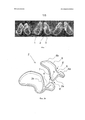
на фиг. 1 показана фотография трех назальных фильтров разного размера;in FIG. 1 shows a photograph of three nasal filters of different sizes;
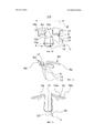
на фиг. 2 показан трехмерный вид каркаса назального фильтра на а) виде в перспективе в косоугольной проекции, b) виде спереди, с) виде сбоку и d) виде сзади;in FIG. 2 shows a three-dimensional view of the nasal filter frame in a) a perspective view in an oblique projection, b) a front view, c) a side view and d) a rear view;
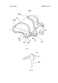
на фиг. 3 показан один участок каркаса с фильтрующим элементом на а) виде сбоку и Ь) на виде сверху;in FIG. 3 shows one section of the frame with a filter element in a) side view and b) in a top view;
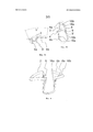
на фиг. 4 показан первый альтернативный вариант осуществления каркаса;in FIG. 4 shows a first alternative embodiment of a carcass;
на фиг. 5 показан второй альтернативный вариант осуществления;in FIG. 5 shows a second alternative embodiment;
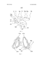
на фиг. 6 показан вид трех каркасов разного размера один над другим;in FIG. 6 shows a view of three frames of different sizes, one above the other;
на фиг. 7 показан каркас по фиг. 2а с базовой плоскостью для иллюстрации геометрических соотношений;in FIG. 7 shows the frame of FIG. 2a with a reference plane to illustrate geometric relationships;
на фиг. 8 показан альтернативный вариант осуществления, иллюстрирующий один участок каркаса с латеральным изгибом вверх и медиальным изгибом вниз.in FIG. 8 is an alternative embodiment illustrating one portion of a carcass with a lateral upward bend and a medial downward bend.
Подробное описаниеDetailed description
На фиг. 1 показана фотография некоторых прототипов назального фильтра 1 разного размера, назальный фильтр содержит каркас 2 и фильтрующий элемент 3, присоединенный к каркасу 2.In FIG. 1 shows a photograph of some prototypes of a
На фиг. 2а показан вид в перспективе одного варианта осуществления каркаса 2 назального фильтра. Каркас 2 содержит U-образную перемычку 4, соединяющую медиальные стороны левого участка 2а каркаса и правого участка 2b каркаса. Перемычка 4 действует как зажим или часть зажима вокруг колумеллы носа.In FIG. 2a shows a perspective view of one embodiment of a
На фиг. 2b, 2с и 2d показаны разные виды в перспективе того же каркаса, что и на фиг. 2а, а именно, на виде спереди, сбоку и сзади, соответственно.In FIG. 2b, 2c and 2d show different perspective views of the same frame as in FIG. 2a, namely, in a front view, a side view, and a rear view, respectively.
Каждый участок 2a, 2b каркаса содержит опорную секцию 6 и соединитель 7, соединяющий перемычку 4 с опорной секцией 6. Опорная секция 6 представляет собой ту часть каркаса 2, которая поддерживает фильтрующий элемент 3. Перемычка 4 действует, как зажим вокруг колумеллы носа; или перемычка 4 в комбинации с соединителем 7 действует, как зажим вокруг колумеллы носа. Перемычка 4 и соединитель 7 представляют собой те части каркаса 2, которые зажимаются вокруг хряща перегородки и, при использовании стоящим человеком, продолжаются вверх и вертикально вдоль перегородки носа. Опорная секция 6 предназначена для поддержания фильтрующего элемента 3, который продолжается через ноздрю. Обычно опорная секция 6 продолжается через ноздрю или окружает ноздрю вдоль стенки ноздри, чтобы поддерживать фильтрующий элемент 3. Опорная секция 6 образует плоскость для фильтрующего элемента, фактически выгнутую изогнутую плоскость. В альтернативном варианте плоскость может быть прямой или вогнутой. Со ссылкой на вариант осуществления по фиг. 1, показано, что площадь, перекрываемая опорной секцией 6, выполнена меньшей, чем площадь фильтрующего элемента 3, чтобы опорная секция 6 необязательно прикасалась к внутренним стенкам ноздрей при использовании назального фильтра 1, однако фильтрующий элемент должен прикасаться к внутренней стенке ноздрей, когда назальный фильтр используется правильным образом. Тот факт, что фильтрующий материал продолжается наружу из опорной секции 6, не является строго обязательным, но обычно более удобен.Each
Поскольку фильтр 1 при использовании обладает типичной ориентацией при использовании стоящим человеком, то принято использовать термины "вверх" и "вниз", "над" и "под" для относительного расположения частей фильтра, не вводя, тем самым, неопределенности, поскольку также принято описывать нос человека с верхней и нижней частями, несмотря на тот факт, что человек может лежать или висеть вниз головой. Термины "передний" или "задний" используются для тех частей, которые предназначены для размещения около передней или задней части ноздри. Термины "медиальный" и "латеральный" используются для тех частей назального фильтра, которые направлены к медиальной части или латеральной части носа, соответственно.Since the
Опорная секция 6 содержит переднюю опорную секцию 6а, которая поддерживает фильтрующий элемент 3 у передней части ноздри, и опорная секция 6 содержит заднюю опорную секцию 6b, которая поддерживает фильтрующий элемент 3 у задней части ноздри. Передняя опорная секция 6а регулируется для разных носов и направляет устройство в правильное положение за счет гибкости упругого средства, описанного подробно далее.The
Далее базовая плоскость 23 указана, как показано на фиг. 7. Базовая плоскость 23 определяется двумя передними точками 21а, 21b передних опорных секций 6а, и двумя наиболее удаленными точками 22а, 22b задних опорных секций 6b. Термин "направление вниз" используется для направления, перпендикулярного базовой плоскости 23, и означает направление к входному отверстию носа для стоящего человека при использовании назального фильтра, хотя следует отметить, что носы различны, и "вниз" необязательно означает вертикально вниз для стоящего человека. Термин "вверх" используется для противоположного направления. Направление, перпендикулярное базовой плоскости 23 определяется вектором 29 нормали к базовой плоскости 23, вектором 29 нормали, определяющим ориентацию базовой плоскости 23 в пространстве.Further, the
Как показано на фиг. 3b, передняя опорная секция 6а содержит медиальный сегмент 18а и латеральный сегмент 18b, причем медиальный сегмент 18а находится около или у перегородки, когда назальный фильтр введен в нос, и латеральный сегмент 18b находится около латеральной стенки ноздри. Задняя опорная секция 6b содержит медиальный сектор 16а и латеральный сектор 16b, причем медиальный сектор 16а находится около или у перегородки, когда назальный фильтр введен в нос, и латеральный сектор 16b находится около латеральной стенки ноздри.As shown in FIG. 3b, the
Как показано на фиг. 2а, между передней опорной секцией 6а и задней опорной секцией 6b выполнен латеральный упругий элемент 8', содержащий латеральный изгиб 8, как часть латеральной стороны участка 2а, 2b каркаса. Как показано на фиг. 3b, латеральный упругий элемент 8' с латеральным изгибом 8 предназначен для плавного изменения расстояния между латеральным сегментом 1 8b и латеральным сектором 16b. В показанном варианте осуществления латеральный изгиб 8 соединяет латеральный сегмент 18b с латеральным сектором 16b.As shown in FIG. 2a, between the
Также, между передней опорной секцией 6а и задней опорной секцией 6b выполнен медиальный упругий элемент 9', содержащий медиальный изгиб 9, как часть медиальной стороны участка 2а, 2b каркаса. Как показано на фиг. 3b, медиальный упругий элемент 9' с медиальным изгибом 9 предназначен для плавного изменения расстояния между медиальным сегментом 18а и медиальным сектором 16а. В показанном варианте осуществления медиальный изгиб 9 соединяет медиальный сегмент 18а с медиальным сектором 16а.Also, between the
Как показано на фиг. 2а, латеральный изгиб 8 соединяет переднюю опорную секцию 6а и заднюю опорную секцию 6b на латеральной стороне участка 2а, 2b каркаса. Аналогично этому медиальный изгиб 9 соединяет переднюю опорную секцию 6а и заднюю опорную секцию 6b на медиальной стороне участка 2а, 2b каркаса. На чертеже видно, что медиальный изгиб 9 является частью соединителя 7. Изгибы 8, 9 придают опорной секции 6 высокую гибкость по сравнению с опорной секцией, которая должна быть сформирована замкнутым кольцом, как предложено в публикации GB 2289846.As shown in FIG. 2a, a
Вогнутость показанного латерального изгиба 8 по форме главным образом круглая, хотя это необязательно. Показанная вогнутость медиального изгиба 9 обладает главным образом U-образной формой со скругленной нижней частью, хотя это необязательно, таким образом, напоминая преимущества конусообразной структуры с точки зрения устойчивости в комбинации с минимализмом плоской структуры для использования преимуществ обеих структур. Поскольку латеральный изгиб 8 обеспечивает некоторую степень гибкости между передней опорной секцией 6а и задней опорной секцией 6b и, в то же самое время, устойчивость против качания, медиальный изгиб 9 обеспечивает некоторую степень гибкости между передней опорной секцией 6а и задней опорной секцией 6b и, в то же самое время, устойчивость вдоль перегородки.The concavity of the
Оба изгиба 8 и 9 показаны с направлением по существу вниз относительно опорной секции, 6 и относительно базовой плоскости 23, что, однако, не является строго обязательным, поскольку один из них или оба могут быть также изогнуты вверх, хотя изгибы 8, 9 вниз считаются более удобными для пользователя. Следует отметить, что термин "вниз" означает от опорной секции 6 в направлении к нижнему концу носа, где перемычка изгибается вокруг колумеллы. Как показано на фиг. 2b и 2 с со ссылкой на фиг. 7, направление радиуса 27 кривизны в нижней части латерального изгиба составляет угол V с нормалью 29 к базовой плоскости, угол V составляет от 0 до 45 градусов, например от 10 до 45 градусов. Таким образом, латеральный изгиб направлен главным образом вниз, хотя в альтернативном варианте он может быть направлен вверх или в виде комбинации латерального изгиба вверх и латерального изгиба вниз. В качестве примера в случае, когда передняя опорная секция 6а и задняя опорная секция 6b, а также латеральный изгиб 8' лежат в одной плоскости, все радиусы кривизны изгиба должны лежать в этой плоскости. Радиус кривизны в нижней части изгиба должен составлять угол с нормалью к базовой плоскости, заданный углом 90 градусов минус угол между вектором нормали к базовой плоскости и вектором нормали к такой плоскости.Both bends 8 and 9 are shown with a substantially downward direction with respect to the
Изгибы 8, 9 приводят к тому, что фильтрующий элемент 3 поддерживается только в передней части ноздри передней опорной секцией 6а и в задней части ноздри задней опорной секцией 6b, поскольку имеется область между передней опорной секцией 6а и задней опорной секцией 6b, в которой фильтрующий элемент 3 не поддерживается. При этом достигается лучшая регулировка фильтрующего элемента 3 внутри носа, что дает лучшее прилегание фильтрующего элемента 3 в ноздре. Повышается общее удобство устройства и улучшается фиксация устройства вдоль кривизны носовой полости. Предпочтительно в этом соединении фильтрующий элемент 3 обладает низкой жесткостью и легко изгибается, когда каркас 2 введен в нос, и передняя опорная секция 6а и задняя опорная секция 6b сдвигаются друг к другу, чтобы приспособиться к форме ноздри.
Гибкость участков 2а, 2b каркаса в направлении от передней опорной секции 6а к задней опорной секции 6b за счет латерального изгиба 8 зависит от глубины латерального изгиба 8 отдельно от других параметров, таких как жесткость и толщина материала. Глубина определяется, как показано на фиг. 7. При переходе между латеральным изгибом 8 и передней опорной секцией 6а имеется первая точка 8а наибольшей кривизны выгнутости, и на переходе между латеральным изгибом 8 и задней опорной секцией 6b имеется вторая точка 8b наибольшей кривизны выгнутости; эти две точки образуют линию 25. В случае, когда латеральный изгиб 8 имеет часть с постоянной кривизной, первая точка 8а и вторая точка 8b определяются как срединные точки дуги с постоянной кривизной.The flexibility of the
Глубина латерального изгиба 8, таким образом, определяется, как расстояние d между линией 25 и самой нижней точкой 8с латерального изгиба 8 при измерении вдоль направления 29', перпендикулярного базовой плоскости 23, причем направление задается вектором 29 нормали. Такое расстояние d составляет по меньшей мере 5% и обычно от 10% до 30% от расстояния D между передней точкой 21b передней опорной секции и задней точкой 22b задней опорной секции. Говоря нематематическими терминами, глубина d латерального изгиба обычно составляет от 10% до 30% длины D участка 2а, b каркаса, который расположен в носу. Для медиального изгиба 8 глубина гораздо больше, обычно от 10% до 80% длины участка 2а, b каркаса.The depth of the
Направление медиального изгиба 9 и латерального изгиба 8 обычно по существу вниз, то есть в основном перпендикулярно базовой плоскости 23. Однако направление латерального изгиба 8 может отклоняться от направления вниз, чтобы способствовать лучшему прилеганию назального фильтра в носу пользователя. Как показано на фиг. 2b, в представленном варианте осуществления направление, показанное наклонной стрелкой 11, латерального изгиба 8 не точно вниз аналогично вектору 29 нормали, а только по существу вниз к колумелле в том смысле, что латеральный изгиб 8 несколько изгибается к латеральным частям носа, что делает его гибким не только в направлении от передней к задней части ноздри, но также вбок, при этом все-таки оставаясь структурно устойчивым в носу. Для полноты следует отметить, что показанная стрелка 11 на фиг. 2b имеет то же направление, что и показанная стрелка 27 для направления радиуса кривизны в нижней части латерального изгиба на фиг. 2с.The direction of the
Также, как показано на фиг. 2b, перемычка 4 является по существу U-образной с плоской нижней частью 12 и ножками 14 для приема самой нижней части перегородки носа между ножками 14. Тем самым, перемычка 4 почти не видна, особенно, когда каркас изготовлен из прозрачного материала. Перемычка 4 обладает первой шириной 13а между ножками проксимально относительно нижней части 12, которая больше, чем вторая ширина 13b между ножками 14, расположенная дистально относительно нижней части 4. Таким образом, кривизна от нижней части 12 U-образной перемычки меняется от вогнутости к выгнутости в направлении вверх вдоль ножек 14. Это предпочтительно для фиксации устройства в носу и на перегородке без блокировки потока воздуха. U-образная перемычка добавляет незначительное давление на стенку перегородки для удержания каркаса 2 в правильном положении и его удержания при физических упражнениях и дыхании.Also, as shown in FIG. 2b, the
Как показано на фиг. 2 с, верхняя поверхность 6а' передней опорной секции 6а и верхняя поверхность 6b'' задней опорной секции 6b расположены друг относительно друга под углом V между ними, например от 5 до 45 градусов, как показано детально на виде сбоку на фиг. 3a. Это приводит к изгибу фильтрующего элемента 3 спереди назад относительно горизонтальной плоскости 23. Эта форма удобна, чтобы направлять пользователя при вставке назального фильтра и его размещении в правильном положении. Она также помогает пользователю размещать назальный фильтр правильно вдоль внутренних стенок ноздрей, тем самым, минимизируя зазоры, несмотря на кривизну носовой полости. Эта особенность также добавляет гибкость назальному фильтру, что важно для комфорта пользователя и плотного прилегания фильтрующего элемента 3 к внутренним стенкам ноздрей.As shown in FIG. 2c, the
Как также показано на фиг. 2с, ножки 14 U-образной перемычки 4 необязательно прямые, а могут быть изогнуты между нижней частью 12 перемычки 4 и опорной секцией 6. Эта кривизна обычно располагается по существу в плоскости 15', параллельной плоскости 15 симметрии между левым участком 2а каркаса и правым участком 2b каркаса, плоскость симметрии показана на фиг. 2d. Эта кривизна ножек 14 в плоскости 15', параллельной плоскости 15 симметрии, помогает в качестве направляющей при введении фильтра и помогает позиционировать устройство в нужном положении, например, чтобы перемычка была почти не видна. Ножка 14 в комбинации с изгибом 9 напоминает форму буквы У.As also shown in FIG. 2c, the
Как также показано на фиг. 2b по сравнению с фиг. 7, ножки 14 U-образной перемычки обычно не перпендикулярны базовой плоскости 23, но обладают углом, меньше 90 градусов, предпочтительно углом от 0 до 10 или от 10 до 20 или от 20 до 30, например, от 5 до 10 или от 5 до 20, градусов с нормалью 29 к базовой плоскости 23. Такой угол около 5 или 10 или 15 градусов от нормали 29 к базовой плоскости 23 приводит к лучшему прилеганию каркаса в носу. В случае, когда ножки 14 выполнены в плоскости 15', параллельной плоскости 15 симметрии, угол, показанный с незначительным преувеличением и обозначенный и на фиг. 2d, измеряется от этой плоскости 15'. Он может обладать направлением по любой стороне этой плоскости 15'.As also shown in FIG. 2b in comparison with FIG. 7, the
На фиг. 3b показан вид сверху фильтра 3 на опоре 6. Латеральные размеры фильтрующего элемента 3 больше, чем площадь, перекрываемая опорной секцией 6, чтобы фильтрующий элемент 3 продолжался дальше к стенкам ноздрей, чем опорная секция 6, чтобы фильтрующий элемент 3 плотно прилегал к внутренним стенкам ноздрей. Например, фильтрующий элемент продолжается на расстояние от 0,5 до 1,5 мм снаружи от опорной секции 6. Больший размер фильтрующего элемента 3 помогает закрыть промежутки между каркасом 2 и внутренними стенками ноздрей для соответствия небольшим различиям носовых полостей у разных людей; кроме того, в зависимости от фильтрующего элемента, он также увеличивает устойчивость и общее удобство варианта осуществления, поскольку он действует в качестве амортизирующего механизма.In FIG. 3b shows a top view of the
До некоторой степени этот принцип известен по упомянутой публикации европейского патента EP 2089115 В1. Однако площадь, перекрываемая опорной секцией 6, больше относительно площади фильтрующего элемента, в том смысле, что фильтрующий элемент предпочтительно больше только на от 3% до 30%, чем площадь, перекрываемая опорной секцией 6, в то время как в публикации ЕР 2089115 В1 площадь фильтрующего элемента больше более чем на 100% (больше более чем в два раза).To some extent, this principle is known from the aforementioned publication of European patent EP 2089115 B1. However, the area covered by the
Как показано на фиг. 3b, задняя опорная секция 6b содержит медиальный сектор 16а и латеральный сектор 16b, причем медиальный сектор 16а находится около или у перегородки, когда назальный фильтр введен в нос, и латеральный сектор 16b находится около латеральной стенки ноздри. Как показано на фиг. 2d, задняя опорная секция 6b обладает уклоном вниз в направлении от медиального сектора 16а к латеральному сектору 16b. Этот уклон вниз обычно составляет от 45 до 85 градусов, например в диапазоне от 70 до 80 градусов, относительно нормали 29 к базовой плоскости 23. Этот уклон повышает гибкость устройства и дает пользователям возможность прикасаться к носу без ощущения дискомфорта. Аналогичным образом, необязательно передняя опорная секция может обладать уклоном для повышения комфорта.As shown in FIG. 3b, the
На фиг. 4 показан один возможный альтернативный вариант осуществления, иллюстрирующий альтернативный каркас 2 на виде спереди в косоугольной проекции. Каркас 2 содержит только медиальный изгиб 9 и не имеет латерального изгиба. Передняя опорная секция 6а сливается с задней опорной секцией 6b на латеральном секторе 16b задней опорной секции 6b. Уклон вниз опорной секции 6 обычно имеет угол от 45 до 85 градусов с вектором 29 нормали; однако он более выражен с более большим углом от медиального сектора 16а к латеральному сектору 16b, чем показано на модели по фиг. 2d. В этом варианте осуществления главным образом медиальный изгиб 9 способствует гибкости каркаса 2 в направлении от передней части к задней части ноздри.In FIG. 4 shows one possible alternative embodiment illustrating an
На фиг. 5 показан вид в косоугольной проекции сбоку другого альтернативного варианта осуществления каркаса 2 для назального фильтра. В этом варианте осуществления каркас 2 содержит медиальные изгибы 9, но не имеет латеральных изгибов. Вместо этого латеральный сектор 16b задней опорной секции 6b не присоединен напрямую к передней опорной секции 6а, а отсоединен от передней опорной секции 6а. Передняя опорная секция 6а содержит медиальный сегмент 18а, предназначенный для размещения около перегородки, и латеральный сегмент 18b, предназначенный для размещения напротив латеральной внутренней стенки ноздри. Латеральный сегмент 18b передней опорной секции 6а и латеральный сектор 16b задней опорной секции 6b не соединены непосредственно, а только опосредованно через медиальный сегмент 18а, медиальный изгиб 9 и медиальный сектор 16а. Между латеральным сегментом 18b передней опорной секции 6а и латеральным сектором 16b задней опорной секции 6b выполнен зазор 17. В показанном варианте осуществления латеральный сегмент 18b передней опорной секции 6а обладает первым концом 19, и латеральный сектор 16b задней опорной секции 6b обладает вторым концом 20 на каждой из сторон зазора 17. Открытая структура, выполненная отсоединением передней опорной секции 6а и задней опорной секции 6b на латеральной стороне участка каркаса обеспечивает гибкость и приспособляемость каркаса 2.In FIG. 5 is an oblique side view of another alternative embodiment of a
В качестве другой альтернативы латеральный сектор 16b задней опорной секции 6b может быть по существу короче, чем показано, например таким коротким, чтобы он заканчивался в указанной концевой точке стрелки 28.As another alternative, the
Вместо наличия изгиба на медиальной стороне и зазора на латеральной стороне возможно изменение на противоположное, а именно, чтобы медиальная сторона была изготовлена аналогично показанной латеральной стороне с зазором 17, и, вместо нее латеральная сторона обладала изгибом, аналогичным изгибу, показанному на фиг. 2а.Instead of having a bend on the medial side and a gap on the lateral side, it is possible to reverse, namely, that the medial side be made in the same way as the lateral side with a
На фиг. 6 показан ряд каркасов разного размера, графически наложенных друг на друга. Построенное изображение показывает, что в этих вариантах осуществления форма каркасов не масштабируется напрямую, а регулируется в соответствии с их размером. В частности, медиальный сектор 16а задней опорной секции 6b обладает разной формой в зависимости от размера каркаса 2. Для увеличения размера медиальный сектор 16а относительно изгибается в большей степени наружу для больших каркасов, чем для меньших каркасов. Таким образом, угол между латеральными сторонами двух участков 2а, 2b каркаса больше для больших моделей, чем для меньших.In FIG. 6 shows a series of frames of different sizes, graphically superimposed on top of each other. The constructed image shows that in these embodiments, the shape of the frames is not scaled directly, but is adjusted in accordance with their size. In particular, the
На фиг. 8 показан вариант осуществления, в котором латеральный изгиб 8 изгибается вверх, в то время как медиальный изгиб 9 изгибается вниз. Для простоты показан только правый участок 2b каркаса. В этом случае может быть предпочтительно, чтобы фильтрующий элемент находится внутри каркаса и не продолжается наружу из каркаса.In FIG. 8 shows an embodiment in which the
Далее некоторые типичные, хотя и не подразумевающие ограничения ими интервалы размеров для использования взрослыми даны в миллиметрах (мм), хотя следует отметить, что размеры для назальных фильтров для детей должны быть меньше. Размеры даны для трех типов фильтров, малый/средний/большой:Further, some typical, although not implied by their limitations, size ranges for use by adults are given in millimeters (mm), although it should be noted that the sizes for nasal filters for children should be smaller. Dimensions are given for three types of filters, small / medium / large:
- глубина d латерального изгиба 8, измеренная от линии 25 (см. фиг. 7): 1,5-5 или 2,5-4;- the depth d of the
- длина D от передней точки 22а, 22b до задней точки 21а, 21b (см. фиг. 7): 10-14/12-16/15-20 или 11-13/14-16/17-20;- the length D from the
- глубина L медиального изгиба 9, измеренная от нижней части изгиба до базовой плоскости 23 (см. фиг. 7): 4-8/5-8/6-9 или 5-8/6-8/6-9;- the depth L of the
- ширина 13а около нижней части 12 U-образной перемычки 4 (см. фиг. 2b): 4-6/5-7/5-7;-
- ширина 13b между ножками 14 на удалении от нижней части 12 U-образной перемычки 4 (см. фиг. 2b): 3-5/4-6/4-6;- the
- ширина W каркаса, как показано на фиг. 2b: 14-21/16-22/19-26 или 15-20/16-21/19-22;- the width W of the frame, as shown in FIG. 2b: 14-21 / 16-22 / 19-26 or 15-20 / 16-21 / 19-22;
- общая высота Η назального фильтра, как показано на фиг. 2b: 8-14/10-15/12-17 или 10-14/14-15/14-16.is the total height Η of the nasal filter, as shown in FIG. 2b: 8-14 / 10-15 / 12-17 or 10-14 / 14-15 / 14-16.
Фильтрующий элемент предпочтительно представляет собой тканый или нетканый фильтр ячеистого типа. Существуют различные способы присоединения фильтрующего элемента 3 к опорному элементу 6, включая, но, не ограничиваясь этим, приклеивание, сварку, расплав, способы с использованием лазера и литье.The filter element is preferably a woven or non-woven mesh filter. There are various ways of attaching the
Claims (22)
Applications Claiming Priority (3)
| Application Number | Priority Date | Filing Date | Title |
|---|---|---|---|
| DKPA201200616 | 2012-10-08 | ||
| DKPA201200616 | 2012-10-08 | ||
| PCT/DK2013/000066 WO2014056501A1 (en) | 2012-10-08 | 2013-10-07 | Nasal filter |
Publications (2)
| Publication Number | Publication Date |
|---|---|
| RU2015116596A RU2015116596A (en) | 2016-11-27 |
| RU2639058C2 true RU2639058C2 (en) | 2017-12-19 |
Family
ID=50476955
Family Applications (1)
| Application Number | Title | Priority Date | Filing Date |
|---|---|---|---|
| RU2015116596A RU2639058C2 (en) | 2012-10-08 | 2013-10-07 | Nasal filter |
Country Status (11)
| Country | Link |
|---|---|
| US (1) | US10758752B2 (en) |
| EP (1) | EP2903699B1 (en) |
| JP (1) | JP6247304B2 (en) |
| CN (1) | CN104703660B (en) |
| AU (1) | AU2013329944B2 (en) |
| BR (1) | BR112015007795A2 (en) |
| CA (1) | CA2926257A1 (en) |
| DK (1) | DK2903699T5 (en) |
| ES (1) | ES2657641T3 (en) |
| RU (1) | RU2639058C2 (en) |
| WO (1) | WO2014056501A1 (en) |
Cited By (1)
| Publication number | Priority date | Publication date | Assignee | Title |
|---|---|---|---|---|
| RU223300U1 (en) * | 2023-10-30 | 2024-02-13 | Владимир Васильевич Галайко | Nasal air filter |
Families Citing this family (2)
| Publication number | Priority date | Publication date | Assignee | Title |
|---|---|---|---|---|
| ES2850287A1 (en) * | 2020-02-26 | 2021-08-26 | Musat Florian Iulian | Nasal prosthesis (Machine-translation by Google Translate, not legally binding) |
| CN114100006B (en) * | 2021-11-23 | 2022-08-02 | 常州市第一人民医院 | Nasal cavity allergen filter |
Citations (5)
| Publication number | Priority date | Publication date | Assignee | Title |
|---|---|---|---|---|
| US2055855A (en) * | 1935-02-25 | 1936-09-29 | Harrison J Weaver | Nasal respirator |
| DE3914606A1 (en) * | 1989-05-03 | 1990-11-08 | Hella Seidel | Pollen filter against hay fever - with plastic frame and plastic filter mesh for nose |
| GB2289846A (en) * | 1994-06-02 | 1995-12-06 | Noreen Hurlin | Nasal filtration device |
| JP2002345986A (en) * | 2001-05-18 | 2002-12-03 | Takeshi Ri | Nose mask |
| RU2352372C2 (en) * | 2004-04-26 | 2009-04-20 | АБУЛЬОН Салвадор ТИРАДО | Anatomic nasal respirator |
Family Cites Families (26)
| Publication number | Priority date | Publication date | Assignee | Title |
|---|---|---|---|---|
| US2046664A (en) | 1935-11-07 | 1936-07-07 | Nasal Filter Co | Nasal filter |
| US2243360A (en) * | 1938-12-30 | 1941-05-27 | Slatis Abraham | Filter or medicament casing |
| US2198959A (en) * | 1939-06-07 | 1940-04-30 | Hubert E Clarke | Nasal filter |
| US2282681A (en) * | 1939-08-14 | 1942-05-12 | Cha Gobe Company | Nasal filter |
| US4052983A (en) * | 1975-09-04 | 1977-10-11 | Bovender Coy R | Nasal filter |
| DE8910651U1 (en) | 1989-05-03 | 1989-11-16 | Seidel, Hella, 8000 Muenchen, De | |
| CN2095679U (en) * | 1991-06-28 | 1992-02-12 | 陈发全 | Dust proof nose cover |
| US5392773A (en) | 1994-04-13 | 1995-02-28 | Bertrand; Archie A. | Respiratory particulate filter |
| US5727543A (en) * | 1997-02-07 | 1998-03-17 | Corsaro; Luigi | Nasal breathing device |
| JP2002345976A (en) | 2001-05-25 | 2002-12-03 | Techno Sonic:Kk | Instrument for iontophoresis |
| US7156098B2 (en) * | 2004-03-19 | 2007-01-02 | Dolezal Creative Innovations, Llc | Breathing air filtration system |
| US8833369B2 (en) | 2004-03-19 | 2014-09-16 | Airware, Inc. | Breathing air filtration devices |
| ITPN20040040A1 (en) | 2004-06-10 | 2004-09-10 | Simone Corinaldesi | FILTERING DEVICE FOR THE NASAL RESPIRATORY TRACT |
| US7156099B1 (en) | 2004-08-03 | 2007-01-02 | Jenkins Cloytillia M | Nostril filtering system |
| ITTV20040056U1 (en) | 2004-10-20 | 2005-01-20 | Dario Toncelli | COMBINED CUTTING MACHINE FOR SLAB MATERIAL PROCESSING. |
| JP2007021156A (en) * | 2005-07-19 | 2007-02-01 | Isao Miyagawa | Tool for preventing invasion of pollen in nose |
| US7354467B2 (en) | 2006-02-21 | 2008-04-08 | Yung-Zhem Chen | Filtering assembly in nasal cavities |
| US20070283963A1 (en) | 2006-06-12 | 2007-12-13 | Sims Guadalupe V | Nose air-filter |
| US20080053448A1 (en) * | 2006-08-31 | 2008-03-06 | Liska Regina B | Nasal filter |
| US20080087286A1 (en) | 2006-10-11 | 2008-04-17 | James Jones | Disposable nasal filter |
| US8110061B2 (en) | 2006-10-31 | 2012-02-07 | Moore Joseph K | Respiratory nasal filter |
| ITMI20062334A1 (en) | 2006-12-05 | 2008-06-06 | Emilio Talmon | AIR FILTER FOR ENDONASAL APPLICATION |
| WO2011041921A1 (en) | 2009-10-09 | 2011-04-14 | Wang Lei | Nose mask |
| JP2011130843A (en) * | 2009-12-22 | 2011-07-07 | Masayasu Nagao | Nostril insert |
| DE202010001203U1 (en) * | 2010-01-21 | 2010-05-20 | Vogel, Jörg | Nose filter for the defense of fine dust |
| JP3159887U (en) * | 2010-03-23 | 2010-06-03 | 株式会社ユタカメイク | Nose mask |
-
2013
- 2013-10-07 CN CN201380051697.9A patent/CN104703660B/en not_active Expired - Fee Related
- 2013-10-07 JP JP2015534913A patent/JP6247304B2/en not_active Expired - Fee Related
- 2013-10-07 CA CA2926257A patent/CA2926257A1/en not_active Abandoned
- 2013-10-07 US US14/434,343 patent/US10758752B2/en active Active
- 2013-10-07 AU AU2013329944A patent/AU2013329944B2/en not_active Ceased
- 2013-10-07 RU RU2015116596A patent/RU2639058C2/en active
- 2013-10-07 ES ES13845501.9T patent/ES2657641T3/en active Active
- 2013-10-07 BR BR112015007795A patent/BR112015007795A2/en not_active Application Discontinuation
- 2013-10-07 WO PCT/DK2013/000066 patent/WO2014056501A1/en active Application Filing
- 2013-10-07 DK DK13845501.9T patent/DK2903699T5/en active
- 2013-10-07 EP EP13845501.9A patent/EP2903699B1/en active Active
Patent Citations (5)
| Publication number | Priority date | Publication date | Assignee | Title |
|---|---|---|---|---|
| US2055855A (en) * | 1935-02-25 | 1936-09-29 | Harrison J Weaver | Nasal respirator |
| DE3914606A1 (en) * | 1989-05-03 | 1990-11-08 | Hella Seidel | Pollen filter against hay fever - with plastic frame and plastic filter mesh for nose |
| GB2289846A (en) * | 1994-06-02 | 1995-12-06 | Noreen Hurlin | Nasal filtration device |
| JP2002345986A (en) * | 2001-05-18 | 2002-12-03 | Takeshi Ri | Nose mask |
| RU2352372C2 (en) * | 2004-04-26 | 2009-04-20 | АБУЛЬОН Салвадор ТИРАДО | Anatomic nasal respirator |
Cited By (1)
| Publication number | Priority date | Publication date | Assignee | Title |
|---|---|---|---|---|
| RU223300U1 (en) * | 2023-10-30 | 2024-02-13 | Владимир Васильевич Галайко | Nasal air filter |
Also Published As
| Publication number | Publication date |
|---|---|
| ES2657641T3 (en) | 2018-03-06 |
| BR112015007795A2 (en) | 2017-07-04 |
| RU2015116596A (en) | 2016-11-27 |
| CN104703660B (en) | 2017-07-21 |
| DK2903699T5 (en) | 2018-02-26 |
| CN104703660A (en) | 2015-06-10 |
| US10758752B2 (en) | 2020-09-01 |
| JP6247304B2 (en) | 2017-12-13 |
| EP2903699B1 (en) | 2017-11-01 |
| AU2013329944A1 (en) | 2015-04-09 |
| US20150265858A1 (en) | 2015-09-24 |
| WO2014056501A1 (en) | 2014-04-17 |
| EP2903699A4 (en) | 2016-05-25 |
| AU2013329944B2 (en) | 2017-11-23 |
| CA2926257A1 (en) | 2014-04-17 |
| JP2015535716A (en) | 2015-12-17 |
| DK2903699T3 (en) | 2018-01-29 |
| EP2903699A1 (en) | 2015-08-12 |
Similar Documents
| Publication | Publication Date | Title |
|---|---|---|
| ES2928472T3 (en) | patient interface | |
| JP6588333B2 (en) | Patient interface and method for forming the patient interface | |
| JP2024045285A (en) | Patient interface and method for forming the patient interface | |
| TWI696474B (en) | Oro-nasal patient interface | |
| RU2582455C2 (en) | Nasal interface | |
| US8834512B1 (en) | Nasal dilator comprising joined legs with end pads and air passages | |
| US11433261B2 (en) | Particle filter mask | |
| JP2016538049A (en) | Patient interface and method for forming a patient interface | |
| JP2015522381A5 (en) | ||
| EP2538877A2 (en) | Nasal dilator | |
| RU2639058C2 (en) | Nasal filter | |
| JP7279215B2 (en) | patient interface | |
| US11213702B1 (en) | Hygiene mask with seal forming structure | |
| KR20220044199A (en) | patient interface | |
| JP2018167042A (en) | Patient interface and method for making that patient interface | |
| US20230240391A1 (en) | Hygiene mask with seal forming structure | |
| CN108434575B (en) | Oronasal patient interface | |
| CN205586388U (en) | Nasal filters | |
| EP4185358A1 (en) | Standalone patient heat and moisture exchanger |