RU2636388C2 - Braking mechanism - Google Patents
Braking mechanism Download PDFInfo
- Publication number
- RU2636388C2 RU2636388C2 RU2015135476A RU2015135476A RU2636388C2 RU 2636388 C2 RU2636388 C2 RU 2636388C2 RU 2015135476 A RU2015135476 A RU 2015135476A RU 2015135476 A RU2015135476 A RU 2015135476A RU 2636388 C2 RU2636388 C2 RU 2636388C2
- Authority
- RU
- Russia
- Prior art keywords
- battery
- spring
- engagement
- handle
- battery holder
- Prior art date
Links
Images


Classifications
-
- B—PERFORMING OPERATIONS; TRANSPORTING
- B26—HAND CUTTING TOOLS; CUTTING; SEVERING
- B26B—HAND-HELD CUTTING TOOLS NOT OTHERWISE PROVIDED FOR
- B26B21/00—Razors of the open or knife type; Safety razors or other shaving implements of the planing type; Hair-trimming devices involving a razor-blade; Equipment therefor
- B26B21/40—Details or accessories
- B26B21/52—Handles, e.g. tiltable, flexible
- B26B21/526—Electric features
-
- B—PERFORMING OPERATIONS; TRANSPORTING
- B26—HAND CUTTING TOOLS; CUTTING; SEVERING
- B26B—HAND-HELD CUTTING TOOLS NOT OTHERWISE PROVIDED FOR
- B26B21/00—Razors of the open or knife type; Safety razors or other shaving implements of the planing type; Hair-trimming devices involving a razor-blade; Equipment therefor
- B26B21/40—Details or accessories
- B26B21/52—Handles, e.g. tiltable, flexible
- B26B21/528—Manufacture of razor handles
-
- H—ELECTRICITY
- H01—ELECTRIC ELEMENTS
- H01M—PROCESSES OR MEANS, e.g. BATTERIES, FOR THE DIRECT CONVERSION OF CHEMICAL ENERGY INTO ELECTRICAL ENERGY
- H01M50/00—Constructional details or processes of manufacture of the non-active parts of electrochemical cells other than fuel cells, e.g. hybrid cells
- H01M50/20—Mountings; Secondary casings or frames; Racks, modules or packs; Suspension devices; Shock absorbers; Transport or carrying devices; Holders
- H01M50/204—Racks, modules or packs for multiple batteries or multiple cells
- H01M50/207—Racks, modules or packs for multiple batteries or multiple cells characterised by their shape
- H01M50/213—Racks, modules or packs for multiple batteries or multiple cells characterised by their shape adapted for cells having curved cross-section, e.g. round or elliptic
-
- H—ELECTRICITY
- H01—ELECTRIC ELEMENTS
- H01M—PROCESSES OR MEANS, e.g. BATTERIES, FOR THE DIRECT CONVERSION OF CHEMICAL ENERGY INTO ELECTRICAL ENERGY
- H01M50/00—Constructional details or processes of manufacture of the non-active parts of electrochemical cells other than fuel cells, e.g. hybrid cells
- H01M50/20—Mountings; Secondary casings or frames; Racks, modules or packs; Suspension devices; Shock absorbers; Transport or carrying devices; Holders
- H01M50/247—Mountings; Secondary casings or frames; Racks, modules or packs; Suspension devices; Shock absorbers; Transport or carrying devices; Holders specially adapted for portable devices, e.g. mobile phones, computers, hand tools or pacemakers
-
- A—HUMAN NECESSITIES
- A61—MEDICAL OR VETERINARY SCIENCE; HYGIENE
- A61C—DENTISTRY; APPARATUS OR METHODS FOR ORAL OR DENTAL HYGIENE
- A61C17/00—Devices for cleaning, polishing, rinsing or drying teeth, teeth cavities or prostheses; Saliva removers; Dental appliances for receiving spittle
- A61C17/16—Power-driven cleaning or polishing devices
-
- Y—GENERAL TAGGING OF NEW TECHNOLOGICAL DEVELOPMENTS; GENERAL TAGGING OF CROSS-SECTIONAL TECHNOLOGIES SPANNING OVER SEVERAL SECTIONS OF THE IPC; TECHNICAL SUBJECTS COVERED BY FORMER USPC CROSS-REFERENCE ART COLLECTIONS [XRACs] AND DIGESTS
- Y02—TECHNOLOGIES OR APPLICATIONS FOR MITIGATION OR ADAPTATION AGAINST CLIMATE CHANGE
- Y02E—REDUCTION OF GREENHOUSE GAS [GHG] EMISSIONS, RELATED TO ENERGY GENERATION, TRANSMISSION OR DISTRIBUTION
- Y02E60/00—Enabling technologies; Technologies with a potential or indirect contribution to GHG emissions mitigation
- Y02E60/10—Energy storage using batteries
Abstract
Description
ОБЛАСТЬ ТЕХНИКИFIELD OF TECHNOLOGY
Настоящее изобретение относится к электрическим приборам или к устройствам, работающим от батарей, таким, как мелкие бытовые приборы, а точнее, к используемым в этих приборах закрывающим элементам.The present invention relates to electrical appliances or to battery-powered devices, such as small household appliances, and more specifically, to the closure elements used in these appliances.
УРОВЕНЬ ТЕХНИКИBACKGROUND
Во многих мелких устройствах, работающих от батарей, замену батарей осуществляет пользователь путем их введения и извлечения из отделения для батарей через отверстие или держатель, имеющий закрывающий элемент или кожух. Во многих случаях необходимо зафиксировать закрывающий элемент на своем месте таким образом, чтобы батареи не выпадали, или чтобы закрывающий элемент самопроизвольно не спадал. Также обычно необходимо обеспечить электрический контакт между батареями и электрической схемой внутри устройства.In many small battery-powered devices, the user replaces the batteries by inserting and removing them from the battery compartment through an opening or holder having a closure member or casing. In many cases, it is necessary to fix the closing element in its place so that the batteries do not fall out, or so that the closing element does not fall off spontaneously. It is also usually necessary to provide electrical contact between the batteries and the electrical circuitry inside the device.
Во время отсоединения закрывающего элемента или кожуха от ручки прибора (например, ручки бритвы) усилие, которое требуется приложить пользователю для отсоединения кожуха, придает кожуху значительную инерцию, что, в свою очередь, снижает контроль пользователя над кожухом и/или батареей.When the closure element or the case is disconnected from the handle of the device (for example, a razor handle), the force that the user needs to exert to disconnect the case gives the case considerable inertia, which in turn reduces the user's control over the case and / or battery.
Таким образом, существует необходимость в механизме с возможностью обеспечения лучшего контроля вмещающего батарею кожуха в процессе его отсоединения или движения при отделении от ручки, чтобы таким образом снизить инерцию батарейного кожуха и обеспечить пользователю гораздо более приятные ощущения при эксплуатации.Thus, there is a need for a mechanism with the ability to provide better control of the housing enclosing the battery during detachment or movement when detached from the handle, thereby reducing the inertia of the battery housing and providing the user with a much more pleasant operating experience.
СУЩНОСТЬ ИЗОБРЕТЕНИЯSUMMARY OF THE INVENTION
Согласно настоящему изобретению, электрический прибор содержит ручку, содержащую верхнюю часть и нижнюю часть, при этом нижняя часть содержит вмещающий батарею кожух с одним или более элементами зацепления, при этом вмещающий батарею кожух притормаживается при отсоединении от верхней части ручки. В еще одном аспекте изобретения, каждый из одного или более элементов зацепления содержит одну или более пружин зацепления, которые могут содержать одну или более выпуклостей. По меньшей мере одна выпуклость может иметь первый криволинейный профиль. Держатель батареи заключен в ручку, имеющую одну или более конструкций зацепления. Одна или более пружин зацепления и одна или более конструкций зацепления установлены соосно вдоль продольной оси ручки. Указанные одна или более конструкции зацепления дополнительно содержат один или более выступов, одно или более углублений или любую их комбинацию, при этом каждый из выступов имеет второй криволинейный профиль, и каждое из указанных одного или более углублений содержит третью вогнутую поверхность. Указанная по меньшей мере одна выпуклость выполнена с возможностью зацепления с одним или более углублениями, одним или более выступами или любой их комбинацией. Первый криволинейный профиль по меньшей мере одной выпуклости выполнен с возможностью зацепления со вторым криволинейным профилем (профилями) одного или более выступов, третьими поверхностями углублений или любой их комбинацией.According to the present invention, the electric device comprises a handle comprising an upper part and a lower part, wherein the lower part comprises a battery holding housing with one or more engagement elements, while the battery holding housing is braked when disconnected from the upper part of the handle. In yet another aspect of the invention, each of one or more engagement elements comprises one or more engagement springs, which may comprise one or more bulges. At least one bulge may have a first curved profile. The battery holder is enclosed in a handle having one or more engagement designs. One or more engagement springs and one or more engagement structures are mounted coaxially along the longitudinal axis of the handle. The said one or more engagement designs further comprise one or more protrusions, one or more recesses, or any combination thereof, each of the protrusions having a second curved profile, and each of the one or more recesses having a third concave surface. Said at least one bulge is adapted to engage with one or more recesses, one or more protrusions, or any combination thereof. The first curvilinear profile of the at least one bulge is adapted to mesh with the second curvilinear profile (s) of one or more protrusions, the third surfaces of the recesses, or any combination thereof.
В еще одном аспекте изобретения вмещающий батарею кожух линейно перемещается вдоль продольной оси ручки во время отсоединения. Такое притормаживание при отсоединении обеспечивает усилие, противодействующее движению вмещающего батарею кожуха. В целом, притормаживание при отсоединении обеспечивается одним или более элементами зацепления или пружинами, остающимися в контакте с одной или более конструкциями зацепления.In yet another aspect of the invention, the battery enclosing casing linearly moves along the longitudinal axis of the handle during disconnection. Such braking upon disconnection provides a force that counteracts the movement of the housing enclosing the battery. In general, braking upon disconnection is provided by one or more meshing elements or springs remaining in contact with one or more meshing structures.
В других аспектах изобретения элемент зацепления выполнен из металла, не обеспечивает электрический контакт с батареей, расположенной в держателе батареи, и прикреплен к вмещающему батарею кожуху. Также, в настоящем изобретении вмещающий батарею кожух не служит для удержания батареи в ручке. Расположенная в держателе батареи батарея обеспечивает питание компонента, такого как электродвигатель прибора.In other aspects of the invention, the engagement member is made of metal, does not provide electrical contact with the battery located in the battery holder, and is attached to the battery housing. Also, in the present invention, the battery holding case does not serve to hold the battery in the handle. A battery located in the battery holder provides power to a component, such as the appliance’s motor.
В других аспектах изобретения по меньшей мере одна выпуклость имеет высоту в диапазоне от приблизительно 0,3 мм до приблизительно 0,7 мм и радиус от приблизительно 0,3 мм до приблизительно 0,6 мм, при этом выступы характеризуются высотой, составляющей от приблизительно 0,2 мм до приблизительно 0,6 мм, радиусом, составляющим приблизительно 0,04 мм до приблизительно 0,5 мм, и расстоянием между первым выступом и вторым выступом, составляющим от приблизительно 1,5 мм до приблизительно 2 мм, или любой их комбинацией.In other aspects of the invention, the at least one bulge has a height in the range of from about 0.3 mm to about 0.7 mm and a radius of from about 0.3 mm to about 0.6 mm, with the protrusions having a height of from about 0 , 2 mm to about 0.6 mm, with a radius of about 0.04 mm to about 0.5 mm, and a distance between the first protrusion and the second protrusion of from about 1.5 mm to about 2 mm, or any combination thereof .
В других аспектах по меньшей мере одна выпуклость расположена на удлиненном участке в виде плеча одного или более элементов зацепления, при этом в непосредственной близости к указанной по меньшей мере одной выпуклости расположена по меньше мере одна плоская область, и при этом участок в виде плеча содержит по меньшей мере один наклонный участок, при этом указанный по меньшей мере один наклонный участок содержит отверстие.In other aspects, the at least one bulge is located on an elongated shoulder portion of one or more engagement elements, wherein at least one planar region is located in close proximity to said at least one bulge, and the shoulder portion comprises at least one inclined portion, wherein said at least one inclined portion comprises an opening.
Электрический прибор согласно настоящему изобретению может быть бритвой, зубной щеткой, устройством для ухода за лицом или электрическим фонариком.The electric device according to the present invention may be a razor, toothbrush, facial device or a flashlight.
В еще одном аспекте настоящего изобретения, прибор содержит ручку по меньшей мере с одной пружиной зацепления в одной части указанной ручки и конструкцией зацепления в другой части указанной ручки, при этом пружина зацепления и конструкция зацепления, будучи соединенными друг с другом, притормаживают отсоединение одной части ручки от другой.In yet another aspect of the present invention, the device comprises a handle with at least one engagement spring in one part of said handle and an engagement design in another part of said handle, wherein the engagement spring and engagement design, when connected to each other, brake the detachment of one part of the handle from another.
Если не указано иное, все технические и научные термины, применяемые в настоящем описании, имеют такое же значение, как и общеизвестное для любого среднего специалиста в области техники, к которой относится изобретение. Несмотря на то, что на практике или при проведении испытаний настоящего изобретения могут быть использованы подобные или эквивалентные методы и материалы, подходящие методы и материалы описаны ниже. Все публикации, патентные заявки, патенты и другие источники, упомянутые в настоящем описании, полностью включены в него посредством ссылки. В случае разногласий, настоящее описание, включающее определения, будет иметь преимущественную силу. Кроме того, материалы, методы и примеры приведены исключительно в качестве примеров и не являются ограничивающими.Unless otherwise specified, all technical and scientific terms used in the present description have the same meaning as well-known to any average specialist in the field of technology to which the invention relates. Although similar or equivalent methods and materials may be used in practice or in testing the present invention, suitable methods and materials are described below. All publications, patent applications, patents and other sources mentioned in the present description are fully incorporated into it by reference. In case of disagreement, the present description, including definitions, will prevail. In addition, materials, methods and examples are provided solely as examples and are not limiting.
Другие признаки и преимущества изобретения станут очевидными из следующего подробного описания, а также формулы изобретения.Other features and advantages of the invention will become apparent from the following detailed description, as well as the claims.
КРАТКОЕ ОПИСАНИЕ ЧЕРТЕЖЕЙBRIEF DESCRIPTION OF THE DRAWINGS
Хотя данное описание завершается формулой изобретения, конкретно указывающей на сущность изобретения и отчетливо заявляющей о содержании настоящего изобретения, предполагается, что лучшему пониманию изобретения будет способствовать описание, приведенное ниже совместно с сопроводительными чертежами, на которых подобные обозначения использованы для указания в сущности идентичных элементов, и на которых:Although this description concludes with a claims that specifically indicate the essence of the invention and clearly state the content of the present invention, it is believed that a better understanding of the invention will be facilitated by the description given below in conjunction with the accompanying drawings, in which similar designations are used to indicate essentially identical elements, and where:
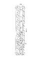
Фиг. 1 - вид в поперечном сечении ручки электрической бритвы для влажного бритья, содержащей элемент зацепления и конструкцию зацепления согласно настоящему изобретению.FIG. 1 is a cross-sectional view of a handle of an electric wet shaver comprising a meshing member and meshing structure according to the present invention.
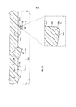
Фиг. 2 - вид в поперечном сечении ручки электрической бритвы для влажного бритья согласно фиг. 1, когда вмещающий батарею кожух отсоединен в продольном направлении согласно настоящему изобретению.FIG. 2 is a cross-sectional view of the handle of an electric wet razor according to FIG. 1 when the battery enclosure is longitudinally disconnected according to the present invention.
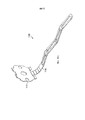
Фиг. 3 - увеличенное схематическое изображение вмещающего батарею кожуха согласно фиг. 1.FIG. 3 is an enlarged schematic illustration of a battery-enclosing housing according to FIG. one.
Фиг. 3а и 3b - вид в перспективе и вид сбоку элемента зацепления согласно настоящему изобретению.FIG. 3a and 3b are a perspective view and a side view of an engagement member according to the present invention.
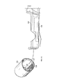
Фиг. 4 - увеличенное схематическое изображение держателя батареи согласно фиг. 1.FIG. 4 is an enlarged schematic illustration of a battery holder according to FIG. one.
Фиг. 5 - увеличенный вид в поперечном сечении выпуклости пружины зацепления в ее положении зацепления с предварительным напряжением с конструкцией зацепления согласно настоящему изобретению.FIG. 5 is an enlarged cross-sectional view of the convexity of the engagement spring in its prestress engagement position with the engagement structure of the present invention.
Фиг. 6 - увеличенный вид в поперечном сечении согласно фиг. 2 выпуклости пружины зацепления при ее линейном перемещении через конструкцию зацепления во время отсоединения вмещающего батарею кожуха.FIG. 6 is an enlarged cross-sectional view according to FIG. 2 the convexity of the engagement spring when it is linearly moved through the engagement structure during detachment of the battery housing.
Фиг. 7 и 7а - увеличенные виды фиг. 6, на которых показано усилие, противодействующее движению вмещающего батарею кожуха согласно настоящему изобретению.FIG. 7 and 7a are enlarged views of FIG. 6, which shows the force counteracting the movement of the battery housing of the casing according to the present invention.
Фиг. 8 - еще один увеличенный вид в поперечном сечении, на котором показана пружина зацепления вмещающего батарею кожуха при ее дальнейшем перемещении через выступ конструкции зацепления держателя батареи согласно настоящему изобретению.FIG. 8 is another enlarged cross-sectional view showing the engagement spring of the housing enclosing the battery as it further moves through the protrusion of the engagement structure of the battery holder according to the present invention.
Фиг. 9 и 9а - предпочтительная геометрия выпуклости пружины зацепления согласно настоящему изобретению.FIG. 9 and 9a are the preferred geometry of the convexity of the engagement spring according to the present invention.
Фиг. 10 - предпочтительная геометрия выступов конструкции зацепления согласно настоящему изобретению.FIG. 10 is a preferred geometry of the protrusions of the engagement structure according to the present invention.
Фиг. 11а, 11b и 11c - вид в перспективе, вид сверху и вид сбоку альтернативного воплощения элемента зацепления согласно настоящему изобретению.FIG. 11a, 11b and 11c are a perspective view, a top view and a side view of an alternative embodiment of an engagement element according to the present invention.
Фиг. 12 - альтернативное воплощение настоящего изобретения, в котором держатель батареи содержит конструкцию зацепления, а вмещающий батарею кожух содержит элемент зацепления, имеющий пружину.FIG. 12 is an alternative embodiment of the present invention, wherein the battery holder comprises an engagement structure, and the battery enclosing housing includes an engagement member having a spring.
ПОДРОБНОЕ ОПИСАНИЕ ИЗОБРЕТЕНИЯDETAILED DESCRIPTION OF THE INVENTION
Новый притормаживающий механизм согласно настоящему изобретению снижает инерцию вмещающего батарею кожуха во время линейного движения при отсоединении от ручки прибора, такого как питающаяся от батарей бритва или бритвенный станок.The new braking mechanism according to the present invention reduces the inertia of the battery housing of the casing during linear movement when the device, such as a battery-powered razor or razor, is disconnected from the handle.
Настоящее изобретение в целом не описывает, каким образом сама батарея удерживается закрепленной в отделении для батарей или держателе при закрытом положении вмещающего батарею кожуха. Также, в целом настоящее изобретение сфокусировано на закрывающем элементе или вмещающем батарею кожухе, отсоединяемом или смещаемом вдоль линейного направления ручки (например, на вмещающем батарею кожухе, выполненном с возможностью перемещения вдоль или в направлении продольной оси ручки). Направление перемещения при таком отсоединении или отделении в целом отличается от направления движения в приборах вмещающими батарею кожухами, отсоединяемыми посредством нелинейного, вращательного движения или движения в поперечном направлении, или таких, в которых вмещающий батарею кожух содержит резьбовое соединение или байонетный механизм (например, многих питающихся от батарей бритв для влажного бритья).The present invention generally does not describe how the battery itself is held secured in the battery compartment or holder when the battery housing housing is closed. Also, in general, the present invention focuses on a cover member or battery holding housing detachable or sliding along the linear direction of the handle (e.g., a battery holding housing configured to move along or in the longitudinal axis of the handle). The direction of movement in such a disconnection or separation is generally different from the direction of movement in the devices by the battery-enclosing housings detachable by non-linear, rotational or lateral movement, or in which the battery-enclosing enclosure contains a threaded connection or a bayonet mechanism (e.g., many powered from wet shaving razors).
Например, фокусируясь на приборе типа питающихся от батарей бритв для влажного бритья, следует отметить, что притормаживающий механизм согласно настоящему изобретению основан на взаимодействии между вмещающим батарею кожухом (на нижнем участке ручки бритвы) и верхним участком ручки бритвы, а именно присутствующим элементом зацепления, имеющим пружину, установленную на внутренней поверхности вмещающего батарею кожуха, входящую в зацепление с внешней поверхностью или с конструкцией зацепления держателя батареи во время движения при отсоединении вмещающего батарею кожуха, что таким образом осуществляет притормаживание или создает эффект задерживания кожуха при отсоединении. Как было указано выше, в целом в настоящем изобретении может использоваться линейное направление отсоединения вдоль продольной оси бритвы.For example, focusing on a device such as battery-powered wet shaving razors, it should be noted that the braking mechanism according to the present invention is based on the interaction between the battery holding casing (in the lower portion of the razor handle) and the upper portion of the razor handle, namely the engagement element present having a spring mounted on the inner surface of the housing enclosing the battery, engaging with the outer surface or with the engagement design of the battery holder during movement when the connection of the enclosure containing the battery, which thus slows down or creates the effect of delaying the casing when disconnected. As indicated above, in general, the linear direction of detachment along the longitudinal axis of the razor can be used in the present invention.
Притормаживающий механизм согласно настоящему изобретению основан на взаимодействии между конструкцией зацепления, сформованной на держателе батареи, и элементом зацепления на пружине зацепления. Во время перемещения вмещающего батарею кожуха пружина зацепления обеспечивает сопротивление, зависящее от ее предварительного напряжения путем сжатия, ее модуля упругости и геометрии конструкции держателя батареи, и в зависимости от интенсивности такого сопротивления этот притормаживающий эффект будет сильнее или слабее.The braking mechanism according to the present invention is based on the interaction between the meshing structure molded on the battery holder and the meshing element on the meshing spring. During the movement of the enclosure enclosing the battery, the engagement spring provides a resistance depending on its prestress by compression, its elastic modulus and the geometry of the structure of the battery holder, and depending on the intensity of such resistance, this braking effect will be stronger or weaker.
Термин ʺпружинаʺ, применяемый в настоящем описании, означает любой тип механической пружины, такой как пружина сжатия, плоская пружина, или любая возможная пружина или их комбинации.The term “spring” as used herein means any type of mechanical spring, such as a compression spring, a flat spring, or any possible spring, or combinations thereof.
Термины ʺвыпуклостьʺ, ʺвыступʺ, ʺуглублениеʺ, применяемые в настоящем описании, могут означать конструкцию любого размера и любой геометрической формы, например, с криволинейным или линейным профилем или с любыми возможными их комбинациями.The terms "convexity", "protrusion", "deepening" used in the present description can mean a construction of any size and any geometric shape, for example, with a curved or linear profile or with any possible combinations thereof.
Термины ʺплоскийʺ или ʺплоские областиʺ, применяемые в настоящем описании, могут означать поверхность, которая выровнена горизонтально, в целом без уклонов, ровную или без явных выступов и впадин.The terms "flat" or "flat areas" used in the present description, can mean a surface that is horizontally aligned, generally without slopes, smooth or without obvious protrusions and depressions.
Термин ʺнаклонныйʺ, применяемый в настоящем описании, может означать поверхность, имеющую один или более углов, расположенную под уклоном или согнутую под каким-либо углом, которая может быть как линейной, так и нелинейной.The term "inclined", as used in the present description, can mean a surface having one or more angles, located at an angle or bent at any angle, which can be either linear or non-linear.
На фиг. 1 показан пример электрического прибора 10 согласно настоящему изобретению, а именно, электрической бритвы для влажного бритья в сборе. Хотя бритва используется и изображена в качестве примера типа электрического прибора согласно настоящему изобретению, настоящее изобретение не ограничивается бритвами и может включать любые другие питающиеся от батарей приборы, такие как зубные щетки, устройства для ухода за лицом или такие приборы, как устройства для пилинга или массажные щетки, или другие устройства для нанесения косметических средств, электрические фонарики и другие широко известные мелкие бытовые электрические приборы.In FIG. 1 shows an example of an
Бритва 10 показана содержащей бритвенный картридж 10а, соединенный с ручкой 12. Ручка 12 содержит несколько компонентов. Ручка 12 обычно имеет верхний участок 12а и нижний участок 12b. Верхний участок 12а содержит держатель 14 батареи внутри ручки 12, батарею 11, расположенную и удерживаемую в держателе 14 батареи, вмещающий батарею кожух 16 в нижнем участке 12b ручки 12, служащую для закрытия или заключения держателя 14 батареи внутри ручки и для обеспечения нижней части ручки, и один или более элементов 18 зацепления во вмещающем батарею кожухе 16.A
Элементы зацепления предпочтительно состоят по меньшей мере из одной пружины. Между батареей 11 и расположенным внутри ручки электродвигателем 19 может быть установлено электрическое соединение. Когда электрическое соединение установлено, осуществляется питание электродвигателя, и он обеспечивает вибрацию, передаваемую на ручку, а затем передаваемую предпочтительно на бритвенный картридж 10а, или в других типах приборов для осуществления питания или приведения в действие функции вибрации любого другого компонента (например, головки щетки).The engagement elements preferably consist of at least one spring. An electrical connection may be established between the
Однако следует отметить, что сама пружина 18 не обеспечивает электрический контакт, необходимый для обеспечения питания бритвы. Фактически, в настоящем изобретении установка батареи 11 в держатель 14 батареи в верхнем участке ручки - это в целом все, что необходимо для обеспечения питания бритвы; ни вмещающий батарею кожух, ни пружина в нижнем участке ручки не являются необходимыми для питания бритвы.However, it should be noted that the
Ручка 12, содержащая вмещающий батарею кожух 16, как показано, обычно выполнена овальной, эллиптической формы, хотя в настоящем изобретении предполагается любая форма этих компонентов, такая, как, в сущности, цилиндрическая форма. Держатель 14 батареи также может иметь овальную, эллиптическую форму для его легкого размещения и ориентации внутри кожуха 16 и ручки 12. Несмотря на то, что схожая форма деталей может обеспечивать удачную ориентацию деталей относительно друг друга, кожух и держатель могут иметь различную форму (например, одна из этих деталей может быть овальной, а другая цилиндрической) при сохранении такой удачной ориентации.The
Тогда как большинство компонентов ручки обычно выполнены из пластиковых материалов, согласно настоящему изобретению пружина 18 зацепления может быть выполнена предпочтительно из металла. Как показано, пружина 18 зацепления предпочтительно может представлять собой пружину сжатия.While most of the components of the handle are usually made of plastic materials, according to the present invention, the
Для извлечения батареи 11 из ручки 12 или для открытия ручки бритвы с другой целью следует снять, отсоединить или отделить вмещающий батарею кожух 16 вдоль продольного направления, как указано стрелкой 22 на фиг. 2.To remove the
Пружина 18 зацепления во вмещающем батарею кожухе 16 может содержать предпочтительно одну или более выпуклостей. Воплощение с одной выпуклостью 18а показано на фиг. 3а и 3b, а альтернативное воплощение с двумя выпуклостями показано на фиг. 11. Показанная на фиг. 3 и 5-8 настоящего изобретения пружина 18 зацепления, содержащая одну выпуклость 18а, расположена во вмещающем батарею кожухе 16.The
Один или более участков пружины 18 зацепления могут быть закреплены на участке 32 нижнего конца внутренней поверхности вмещающего батарею кожуха 16, как показано на фиг. 3. Как ясно показано на фиг. 3, 3а и 3b, пружина 18 зацепления имеет в целом закругленный участок 18', прикрепленный к внутренней поверхности 32 нижнего конца 16' вмещающего батарею кожуха 16, и по меньшей мере один участок 18ʺ в виде плеча, протяженный от закругленного участка 18' в продольном направлении от нижнего конца 32 в целом вдоль оси ручки. 3акругленный участок 18' может быть установлен или закреплен на вмещающем батарею кожухе посредством посадки с натягом, ультразвуковой сварки, или любого возможного способа крепления или соединения, или их комбинации.One or more portions of the
На фиг. 3а закругленный участок 18' показан имеющим ширину 31 предпочтительно приблизительно от 8 мм до приблизительно 10 мм и более предпочтительно приблизительно 9,15 мм, а участок 18ʺ в виде плеча показан имеющим ширину 33 предпочтительно приблизительно от 1,5 мм до приблизительно 2,5 мм и более предпочтительно приблизительно 2 мм.In FIG. 3a, the rounded
Как показано на фиг. 3b, участок 18ʺ в виде плеча предпочтительно может содержать линейный участок 34 и наклонные участки 35а и 35b, охватывающие с обеих сторон выпуклость 18а.As shown in FIG. 3b, the shoulder-shaped portion 18ʺ may preferably comprise a
Наклонные участки 35а и 35b в предпочтительно являются в сущности симметричными, однако настоящее изобретение предполагает и несимметричные участки. Линейный участок 34 предпочтительно может составлять приблизительно половину длины всего участка 18ʺ в виде плеча, однако настоящее изобретение предполагает любую возможную длину. В целом, теоретически, чем длиннее линейный участок 34, тем больше удерживающее усилие. Кроме того, обеспечение большей ширины 33 участка 18ʺ в виде плеча позволяет сделать область более плоской или сделать наклонные участки более приближенными к линейным.The
Каждый из наклонных участков 35а и 35b предпочтительно может иметь одно или более отверстий 36а и 36b. Как показано на фиг. 3а, наклонный участок 35а имеет одно отверстие 36а, и наклонный участок 35b имеет одно отверстие 36b. Хотя для настоящего изобретения это является необязательным, отверстия 36а и 36b могут в целом обеспечивать некоторые преимущества, такие как равномерность усилия на наклонных участках 35а и 35b во время сжатия пружины 18.Each of the
Более равномерное распределение напряжения на участке 18ʺ в виде плеча может быть достигнуто при наличии отверстий в наклонных участках, таким образом, на плече может быть скомпенсировано более высокое напряжение, и, следовательно, пружина предпочтительно может быть сжата с минимальной остаточной деформацией. Размер и форма отверстий могут быть определены и соответствующим образом реализованы, в зависимости от точки, в которой необходимо достичь распределения напряжения. Размер и форма отверстий предпочтительно могут быть достаточно малыми, чтобы не создавать помех притормаживающему механизму конструкции зацепления, обеспечиваемому держателем батареи.A more uniform stress distribution in the shoulder portion 18ʺ can be achieved by having holes in the inclined portions, so that a higher stress can be compensated on the shoulder, and therefore, the spring can preferably be compressed with minimal residual deformation. The size and shape of the holes can be determined and suitably implemented, depending on the point at which the stress distribution needs to be achieved. The size and shape of the holes may preferably be small enough so as not to interfere with the braking mechanism of the engagement structure provided by the battery holder.
Пружина 18 зацепления в целом может рассматриваться в предварительно напряженном сжатом состоянии, когда ручка полностью сформирована или собрана, как показано, например, на фиг. 1 и фиг. 5.The
Когда вмещающий батарею кожух 16 закреплен или установлен на ручке 12 бритвы, обеспечивая закрытое положение ручки (например, кожух не спадает с верхнего участка 12а ручки 12), как показано на фиг. 1, участок 18ʺ в виде плеча пружины зацепления простирается в продольном направлении почти по всей длине кожуха 14.When the
В этом положении, когда вмещающий батарею кожух надет на держатель батареи и бритва готова к использованию, ручка бритвы в целом также является водонепроницаемой.In this position, when the battery-enclosing casing is put on the battery holder and the razor is ready for use, the razor handle is also generally waterproof.
Выпуклость 18а пружины 18 зацепления предпочтительно может быть в непосредственном и, в сущности, постоянном контакте по меньшей мере с одним участком конструкции 42 зацепления (фиг. 1, 4), расположенной на держателе 14 батареи. Пружина 18, а конкретнее, по меньшей мере ее участок 18ʺ в виде плеча, является в целом соосной с конструкцией 42 зацепления.The
Конструкция 42 зацепления, более подробно показанная на фиг. 4, предпочтительно может быть сформована как одно целое с внешней поверхностью 42а держателя 14 батареи. Настоящее изобретение также предполагает воплощение, в котором конструкция 42 зацепления является сформированной отдельно и прикрепленной к кожуху, или даже состоящей из материала, отличного от материала кожуха. Например, кожух может быть изготовлен из пластика, а конструкция зацепления может состоять из металла, или наоборот.The
Конструкция 42 зацепления, как показано на фиг. 4, предпочтительно состоит из одного или более небольших выступов 44 и одного или более углублений 46 и расположена на кожухе в продольной ориентации таким образом, чтобы предпочтительно входить в зацепление с выпуклостью 18а, находящейся на продольном участке 18ʺ в виде плеча пружины 18 зацепления.The
На фиг. 5 изображен увеличенный вид в поперечном сечении ручки в закрытом положении, как показано на фиг. 1. Пружина имеет одну выпуклость 18а, а конструкция 42 зацепления имеет множество выступов 44 и углублений 46, расположенных на поверхности 42а и соосных с участком 18ʺ в виде плеча пружины 18.In FIG. 5 is an enlarged cross-sectional view of the handle in the closed position, as shown in FIG. 1. The spring has one
На фиг. 6-8 показана последовательность схематических изображений отсоединения или отделения вмещающего батарею кожуха от ручки. При начальном отсоединении вмещающего батарею кожуха 16 в линейном направлении (отделении или снятии с участка 12а ручки) выпуклость 18а пружины перемещается в линейном направлении вдоль конструкции 42 зацепления держателя 14 батареи. Во время движения при отсоединении вмещающего батарею кожуха небольшая выпуклость 18а пружины зацепления сталкивается с первым углублением 46а (показано на фиг. 6), затем с первым небольшим выступом 44а (показан на фиг. 6-7) конструкции 42 зацепления кожуха 14, что обеспечивает, в сущности, усилие F (показанное стрелкой F усилия на фиг. 7) или сопротивление движению пружины 18' в продольном направлении, обеспечивая более контролируемое отсоединение кожуха от ручки. При дальнейшем отсоединении вмещающего батарею кожуха 16 выпуклость 18а пружины зацепления сталкивается со вторым углублением 46b, а затем со вторым небольшим выступом 44b конструкции 42 зацепления кожуха 14 и так далее.In FIG. 6-8 show a sequence of schematic illustrations of disconnecting or separating a battery-enclosing housing from a handle. Upon initial detachment of the
Усилие F в целом приложено в противоположном направлении относительно движения вмещающего батарею кожуха, как показано стрелкой ‘‘F’’ усилия на фиг. 7. Поскольку пружина 18 зацепления установлена на вмещающим батарею кожухе 16, усилие F также действует непосредственно на пружину 18, и именно это сопротивление обеспечивает основной принцип настоящего изобретения, выполняющего функцию притормаживающего механизма.The force F is generally applied in the opposite direction with respect to the movement of the battery housing, as indicated by the arrow ‘‘ F ’’ of the force in FIG. 7. Since the
Как показано на фиг. 6-9, выпуклость 18а пружины 18 зацепления может в целом преодолевать каждый из одного или более выступов 46 конструкции 42 зацепления на кожухе 14, в основном благодаря гибкости пружины 18 зацепления и криволинейным внешней поверхности или профилю 18а' выпуклости 18а. При отсоединении криволинейный профиль 18а' выпуклости 18а входит в зацепление и остается, в сущности, в контакте последовательно с каждым из криволинейных профилей 44а', 44b', 44 с' и т.д. одного или более выступов 44а, 44b, 44с на конструкции 14 зацепления и вогнутыми поверхностями 46а', 46b', 46 с' и т.д. одного или более углублений 46а, 46b, 46с и т.д. конструкции 14 зацепления, или любой их комбинации.As shown in FIG. 6-9, the
Некоторые параметры могут способствовать обеспечению оптимальной работы механизма согласно настоящему изобретению. Сопротивление или усилие F, которое предпочтительно удерживает пружину 18 зацепления, зависит от многих параметров, например от материала и геометрии пружины зацепления, обработанных поверхностей областей, находящихся в контакте, которые могут в целом влиять на коэффициент трения, от предварительного напряжения путем сжатия пружины зацепления, геометрии одной или более выпуклостей на пружине зацепления и геометрии одного или более выступов и впадин на конструкции зацепления.Some parameters may help to ensure optimal operation of the mechanism according to the present invention. The resistance or force F, which preferably holds the
Выбранный тип материала пружины зацепления обычно важен для ее способности обеспечивать гибкое или упругое действие. Дополнительно, как было указано выше, пружина состоит предпочтительно из металла для обеспечения долговечного элемента зацепления с длительным сроком службы.The selected type of engagement spring material is usually important for its ability to provide a flexible or resilient action. Additionally, as mentioned above, the spring is preferably made of metal to provide a durable engaging element with a long service life.
В одном предпочтительном воплощении пружина состоит из твердого металла любого типа. В целом предпочтительный тип металла в настоящем изобретении может, кроме прочего, иметь характеристику твердости согласно нормам или стандартам Немецкого института стандартов (DIN), соответствующую стандарту DIN приблизительно 1.4310+С1150 с диапазоном предела прочности на разрыв от приблизительно 1150 Н/мм2 до приблизительно 1300 Н/мм2. При необходимости, он может быть закален до возможного достижения более высокого предела прочности на разрыв. Посредством закалки предсказуемо может быть достигнуто повышение предела прочности на разрыв в целом на приблизительно от 10 до 20 процентов. Может быть выбран другой тип металла, имеющий твердость согласно стандарту DIN приблизительно 1.4310+С1300 (например, нержавеющая сталь SUS 301-Н), чтобы в целом обеспечивать подобный предел прочности на разрыв от приблизительно 1300 Н/мм2 до приблизительно 1500 Н/мм2 (+С1300). Что касается стандарта +С1150, он необязательно может быть обеспечен дополнительным процессом закаливания.In one preferred embodiment, the spring consists of any type of solid metal. In general, the preferred type of metal in the present invention may, inter alia, have a hardness characteristic according to the norms or standards of the German Institute of Standards (DIN), corresponding to DIN 1.4310 + C1150 with a tensile strength range from about 1150 N / mm 2 to about 1300 N / mm 2 . If necessary, it can be hardened to the possible achievement of a higher tensile strength. Through quenching, a predictable increase in overall tensile strength by about 10 to 20 percent can be achieved. A different type of metal may be selected having a hardness according to DIN of approximately 1.4310 + C1300 (for example, SUS 301-H stainless steel) to generally provide a similar tensile strength of from about 1300 N / mm 2 to about 1500 N / mm 2 (+ C1300). As for the standard + C1150, it may not necessarily be provided with an additional hardening process.
Как показано на фиг. 9 и 9а, геометрия выпуклости пружины 18 зацепления предпочтительно может обеспечивать оптимальный эффект притормаживания. Предпочтительный радиус 92 выпуклости 18а может предпочтительно находиться в диапазоне от приблизительно 0,3 мм до приблизительно 0,6 мм и более предпочтительно составлять приблизительно 0,4 мм. Предпочтительная высота 94 выпуклости может предпочтительно находиться в диапазоне от приблизительно 0,3 мм до приблизительно 0,7 мм и более предпочтительно составлять приблизительно 0,4 мм.As shown in FIG. 9 and 9a, the convex geometry of the
Также, оптимальная длина 98 участка 18ʺ в виде плеча может предпочтительно находиться в диапазоне от приблизительно 12 мм до приблизительно 15 мм и предпочтительно составлять приблизительно 13 мм. Участок 18ʺ в виде плеча может иметь изгиб в месте выпуклости (как показано двумя наклонными участками, расположенными по бокам выпуклости на фиг. 9) или, альтернативно, может располагаться в виде другой нелинейной конструкции или, в сущности, прямой линии. Дальний конец 52 (показанный на фиг. 5-9) пружины 18 предпочтительно, в сущности ,представляет собой свободный конец и не прикреплен к другому компоненту. Однако в настоящем изобретении также предполагается, что участок 18ʺ в виде плеча или его конец может быть выполнен с возможностью ориентации, или он может быть частично либо полностью закреплен. Высота 97 пружины 18 приблизительно от верхней поверхности 52а конца 52 до плоской области 96 предпочтительно составляет от приблизительно 1 мм до приблизительно 1,7 мм и предпочтительно составляет приблизительно 1,4 мм. Высота 97, в отличие от высоты 57, в целом представляет собой физическую высоту пружины в несжатом состоянии (например, когда элемент зацепления еще не установлен на вмещающем батарею кожухе).Also, the
Также, показанные на фиг. 9 одна или более плоских областей 96 могут быть расположены с любой или с обеих сторон выпуклости и, по сути, сформированы таким образом, чтобы исключить деформации выпуклости во время движения при сжатии пружины 18 зацепления, поскольку любые деформации выпуклости, вероятно, могут способствовать созданию нежелательного снижения усилия F удерживания. При наличии двух плоских областей 96 обеспечивается лучшее распределение напряжения, что таким образом в целом минимизирует эти деформации. Предпочтительная длина 96а для каждой плоской области 96 может предпочтительно составлять от приблизительно 0,8 мм до приблизительно 1,2 мм и более предпочтительно составлять 1 мм. В целом участок в виде плеча или пружина предпочтительно может иметь тем большую механическую жесткость, чем короче длина плоской области.Also shown in FIG. 9, one or more
Предварительное напряжение путем сжатия пружины зацепления, которое служит для обеспечения оптимального усилия удерживания и минимальной деформации пружины зацепления может зависеть от высоты пружины зацепления и относительного положения выступа зацепления на поверхности 42а держателя батареи. В настоящем изобретении оптимальная высота 57 предварительного напряжения или высота в сжатом состоянии предпочтительно может составлять от приблизительно 0,8 мм до приблизительно 1,2 мм и более предпочтительно приблизительно 1,1 мм, как показано на фиг. 5. Эта высота 57 предварительного напряжения, как показано, предпочтительно может в целом быть высотой от конца верхней поверхности 52а до приблизительно верхней части криволинейного профиля 18а' выпуклости и представляет собой состояние пружины, когда вмещающий батарею кожух 16 соединен или собран с держателем 14 и выпуклость 18а пружины 18 расположена в одном из углублений 46.The prestress by compressing the engagement spring, which serves to provide optimum holding force and minimal deformation of the engagement spring, may depend on the height of the engagement spring and the relative position of the engagement protrusion on the
Как показано на фиг. 10 и 10а, расстояние 104, в сущности, между выступами 44 на держателе 14 батареи предпочтительно может находиться в диапазоне от приблизительно 1,5 мм до приблизительно 2 мм и более предпочтительно составлять 1,7 мм. Размер 106 радиуса выступа 44 предпочтительно может находиться в диапазоне от приблизительно 0,04 мм до приблизительно 0,5 мм и предпочтительно составлять приблизительно 0,4 мм и более предпочтительно приблизительно 0,08 мм. Высота 105 выступа 44 предпочтительно может находиться в диапазоне от приблизительно 0,2 мм до приблизительно 0,6 мм и более предпочтительно составлять приблизительно 0,3 мм. Следует отметить, что не все выступы или углубления на конструкции зацепления держателя батареи должны быть идентичными или иметь идентичные размеры, в то время, как настоящее изобретение предполагает любую геометрию каждого выступа и/или впадины и любое расстояние между ними. Высота 105 предпочтительно может быть определена как расстояние по прямой от точки R1 на вершине выступа до точки R2 или R3 основания выступа. Если точки основания выступов не находятся на горизонтальной линии, то высота может быть определена от точки основания, самой удаленной от точки R1 вершины.As shown in FIG. 10 and 10a, the
Как показано на фиг. 10, угол 107 зацепления показан составляющим приблизительно 90°. Согласно настоящему изобретению угол, образованный боковой стороной 107а выступа и горизонтальной линией 108, на которой в целом расположен выступ, находится в диапазоне от приблизительно 60° до приблизительно 90°, предпочтительно составляет 70° и более предпочтительно приблизительно 80° и наиболее предпочтительно приблизительно 90°. Боковая линия 109 предпочтительно может быть определена на боковой стороне 107а выступа, как прямая от точки R1 на вершине выступа до точки R2 на области 108а основания выступа. Как показано на фиг. 10, боковая линия 109 является прямой, перпендикулярной горизонтальной линии 108. Угол 107 зацепления предпочтительно может быть определен углом, образованным между вершиной R1 и вершиной R3 в другой точке основания выступа (например, такой как R2 на другой стороне основания 108а выступа). В целом горизонтальная линия 108 выступов может быть, в сущности, параллельна пружине зацепления (не показана) согласно настоящему изобретению.As shown in FIG. 10, an
В целом угол зацепления и усилие F зацепления непосредственно связаны таким образом, что больший угол может обеспечивать большее усилие зацепления, а меньший угол может обеспечивать меньшее усилие зацепления. Таким образом, максимальное усилие может быть получено при угле 107 зацепления, составляющем приблизительно 90°. Если угол превышает 90°, может возникнуть вероятность повреждения пружины зацепления согласно настоящему изобретению.In general, the engagement angle and the engagement force F are directly related so that a larger angle can provide more engagement force, and a smaller angle can provide less engagement force. Thus, maximum force can be obtained with an angle of
На фиг. 11а, 11b и 11с изображены виды альтернативного воплощения элемента 110 зацепления согласно настоящему изобретению. На фиг. 11 закругленный участок 11 обеспечен содержащим протяженный от него участок 112 в виде плеча. Участок 112 в виде плеча опционально может быть обеспечен одним линейным участком 114 и также может в целом иметь по меньшей мере две выпуклости 113а и 113b и наклонные участки на каждой из сторон этих двух выпуклостей. Как показано, наклонные участки являются симметричными или имеют одинаковую длину и угол, однако, как описано выше со ссылкой на фиг. 3а, 3b, настоящее изобретение также может предполагать асимметричные наклонные участки.In FIG. 11a, 11b, and 11c depict views of an alternative embodiment of an
Как показано на фиг. 11b, каждый из наклонных участков 115а, 115b, 117а, 117b может иметь расположенное в нем отверстие 116а, 116b, 118а, 118b, при этом отверстия являются отверстиями типа, описанного в настоящем описании. Так же, как показано на фиг. 11с, непосредственно вблизи каждой выпуклости расположены одна или более плоских областей 113.As shown in FIG. 11b, each of the
На фиг. 12 изображено альтернативное воплощение настоящего изобретения, в котором держатель 122 батареи содержит элемент 123 зацепления с одной или более пружинами 124, и вмещающий батарею кожух 125 содержит конструкцию 126 зацепления с одним или более выступами 127 и/или одним или более углублениями 128. Взаимосвязь и функции элемента 123 зацепления и конструкции 126 зацепления, теоретически, в целом подобны функциям, описанным ранее в настоящем описании.In FIG. 12 depicts an alternative embodiment of the present invention in which the
Размеры и значения, раскрытые в данном описании, не следует понимать как строго ограниченные указанными точными числовыми значениями. Наоборот, если не указано иначе, каждый такой размер следует подразумевать, и как указанное значение, и как функционально эквивалентный диапазон, охватывающий данное значение. Например, размер, указанный как “400 мм”, следует понимать, как “приблизительно 40 мм”.The dimensions and values disclosed herein are not to be understood as being strictly limited to the indicated exact numerical values. On the contrary, unless otherwise indicated, each such size should be implied, both as a specified value, and as a functionally equivalent range, covering this value. For example, a dimension indicated as “400 mm” should be understood as “approximately 40 mm”.
Каждый документ, упомянутый в настоящем описании, в том числе любая перекрестная ссылка или родственные патент или заявка, настоящим в полном объеме включены в данное описание посредством ссылки, за исключением четко указанных исключений или иных ограничений. Цитирование любого документа не является допущением того, что он является прототипом любого раскрытого или заявленного в настоящем описании изобретения, или того, что он сам, или в сочетании с другим источником или источниками дает пояснения, предположения или раскрывает любое из этих изобретений. Также, в том случае, если любое значение или определение какого-либо термина в данном документе противоречит любому значению или определению такого же термина в документе, включенном по ссылке, значение или определение, присвоенное такому термину в данном документе, должно иметь приоритетное значение.Each document referred to in this description, including any cross-reference or related patent or application, is hereby fully incorporated into this description by reference, with the exception of clearly indicated exceptions or other restrictions. The citation of any document is not an assumption that it is a prototype of any disclosed or claimed invention, or that it, itself, or in combination with another source or sources, provides explanations, assumptions or discloses any of these inventions. Also, in the event that any meaning or definition of a term in this document contradicts any meaning or definition of the same term in a document incorporated by reference, the value or definition assigned to such a term in this document shall have priority.
Хотя были проиллюстрированы и описаны конкретные воплощения данного изобретения, специалистам в данной области будет очевидно, что могут быть выполнены различные другие изменения и модификации без отклонения от сущности и объема данного изобретения. Таким образом в прилагаемой формуле изобретения предполагается охватить все такие изменения и модификации, входящие в объем данного изобретения.Although specific embodiments of the invention have been illustrated and described, it will be apparent to those skilled in the art that various other changes and modifications can be made without departing from the spirit and scope of the invention. Thus, the appended claims are intended to cover all such changes and modifications that are within the scope of this invention.
Claims (14)
Applications Claiming Priority (3)
| Application Number | Priority Date | Filing Date | Title |
|---|---|---|---|
| US201361805348P | 2013-03-26 | 2013-03-26 | |
| US61/805,348 | 2013-03-26 | ||
| PCT/US2014/031733 WO2014160713A1 (en) | 2013-03-26 | 2014-03-25 | Retarding mechanism |
Publications (2)
| Publication Number | Publication Date |
|---|---|
| RU2015135476A RU2015135476A (en) | 2017-04-28 |
| RU2636388C2 true RU2636388C2 (en) | 2017-11-23 |
Family
ID=50640005
Family Applications (1)
| Application Number | Title | Priority Date | Filing Date |
|---|---|---|---|
| RU2015135476A RU2636388C2 (en) | 2013-03-26 | 2014-03-25 | Braking mechanism |
Country Status (10)
| Country | Link |
|---|---|
| US (1) | US10147918B2 (en) |
| EP (1) | EP2979316B1 (en) |
| JP (2) | JP2016515427A (en) |
| CN (1) | CN105051939B (en) |
| BR (1) | BR112015024273A2 (en) |
| MX (1) | MX2015013588A (en) |
| PL (1) | PL2979316T3 (en) |
| RU (1) | RU2636388C2 (en) |
| SG (1) | SG11201506747YA (en) |
| WO (1) | WO2014160713A1 (en) |
Families Citing this family (1)
| Publication number | Priority date | Publication date | Assignee | Title |
|---|---|---|---|---|
| CN106601946A (en) * | 2016-11-09 | 2017-04-26 | 成都聚立汇信科技有限公司 | Battery holder |
Citations (4)
| Publication number | Priority date | Publication date | Assignee | Title |
|---|---|---|---|---|
| US20070050997A1 (en) * | 2005-09-06 | 2007-03-08 | Fred Schnak | Razors |
| RU2384917C2 (en) * | 2005-04-27 | 2010-03-20 | Дзе Жиллетт Компани | Devices operating from accumulators |
| RU2415747C1 (en) * | 2007-02-01 | 2011-04-10 | БРАУН ГмбХ | Device for hair removal |
| US20110214289A1 (en) * | 2010-03-03 | 2011-09-08 | Michael Maichel | Combination powered grooming device |
Family Cites Families (11)
| Publication number | Priority date | Publication date | Assignee | Title |
|---|---|---|---|---|
| JPS60106484A (en) * | 1983-11-14 | 1985-06-11 | 松下電工株式会社 | Electric razor |
| JPS63181788A (en) * | 1987-01-23 | 1988-07-26 | 松下電工株式会社 | Battery holding structure of battery machinery |
| GB8820230D0 (en) | 1988-08-25 | 1988-09-28 | Steeper Hugh Ltd | Battery & battery receptacle arrangement |
| US5430967A (en) | 1993-12-16 | 1995-07-11 | Insight Technology, Inc. | Aiming assistance device for a weapon |
| US5544415A (en) * | 1994-12-06 | 1996-08-13 | Kunnex Incorporated | Water-proof and washable electric razor |
| JP2000089846A (en) * | 1998-09-08 | 2000-03-31 | Asahi Optical Co Ltd | Click mechanism |
| JP4069596B2 (en) * | 2001-06-14 | 2008-04-02 | 松下電工株式会社 | Cover body mounting structure |
| US7637014B2 (en) * | 2005-09-06 | 2009-12-29 | The Gillette Company | Razors |
| US20070050996A1 (en) | 2005-09-06 | 2007-03-08 | Fred Schnak | Razors |
| US7780309B2 (en) * | 2007-06-05 | 2010-08-24 | Eveready Battery Company, Inc. | Preparedness flashlight |
| JP5349866B2 (en) * | 2008-08-22 | 2013-11-20 | キヤノン株式会社 | Electronics |
-
2014
- 2014-03-25 EP EP14721680.8A patent/EP2979316B1/en active Active
- 2014-03-25 BR BR112015024273A patent/BR112015024273A2/en not_active IP Right Cessation
- 2014-03-25 PL PL14721680T patent/PL2979316T3/en unknown
- 2014-03-25 MX MX2015013588A patent/MX2015013588A/en unknown
- 2014-03-25 WO PCT/US2014/031733 patent/WO2014160713A1/en active Application Filing
- 2014-03-25 SG SG11201506747YA patent/SG11201506747YA/en unknown
- 2014-03-25 CN CN201480017720.7A patent/CN105051939B/en active Active
- 2014-03-25 RU RU2015135476A patent/RU2636388C2/en not_active IP Right Cessation
- 2014-03-25 US US14/224,382 patent/US10147918B2/en active Active
- 2014-03-25 JP JP2016505539A patent/JP2016515427A/en active Pending
-
2017
- 2017-08-03 JP JP2017150426A patent/JP6517887B2/en active Active
Patent Citations (5)
| Publication number | Priority date | Publication date | Assignee | Title |
|---|---|---|---|---|
| RU2384917C2 (en) * | 2005-04-27 | 2010-03-20 | Дзе Жиллетт Компани | Devices operating from accumulators |
| US20070050997A1 (en) * | 2005-09-06 | 2007-03-08 | Fred Schnak | Razors |
| RU2404046C2 (en) * | 2005-09-06 | 2010-11-20 | Дзе Жиллетт Компани | Handle of safety electric razor |
| RU2415747C1 (en) * | 2007-02-01 | 2011-04-10 | БРАУН ГмбХ | Device for hair removal |
| US20110214289A1 (en) * | 2010-03-03 | 2011-09-08 | Michael Maichel | Combination powered grooming device |
Also Published As
| Publication number | Publication date |
|---|---|
| US20140295236A1 (en) | 2014-10-02 |
| MX2015013588A (en) | 2016-02-05 |
| PL2979316T3 (en) | 2018-04-30 |
| EP2979316B1 (en) | 2017-12-06 |
| CN105051939A (en) | 2015-11-11 |
| CN105051939B (en) | 2019-09-17 |
| RU2015135476A (en) | 2017-04-28 |
| JP2016515427A (en) | 2016-05-30 |
| WO2014160713A1 (en) | 2014-10-02 |
| JP2017205581A (en) | 2017-11-24 |
| US10147918B2 (en) | 2018-12-04 |
| EP2979316A1 (en) | 2016-02-03 |
| SG11201506747YA (en) | 2015-09-29 |
| JP6517887B2 (en) | 2019-05-22 |
| BR112015024273A2 (en) | 2017-07-18 |
Similar Documents
| Publication | Publication Date | Title |
|---|---|---|
| JP5860898B2 (en) | Brush head for power toothbrush with wedge and spring handle interface | |
| KR101522160B1 (en) | Shaving device comprising a pivotably arranged assembly of cutting elements | |
| JP5174808B2 (en) | Cutting device and hair cutting instrument | |
| EP1875531B1 (en) | Battery-operated appliances | |
| US20140309566A1 (en) | Attachment for Epilator and Epilator | |
| TW200841864A (en) | Electrically driven toothbrush | |
| JP2009028310A (en) | Electric toothbrush | |
| RU2549542C2 (en) | Stiff structure of eccentric con-rod and generator of vibrations | |
| WO2013014632A1 (en) | Linear electro-polymer motors and devices having the same | |
| EP3689293B1 (en) | Care unit | |
| RU2636388C2 (en) | Braking mechanism | |
| CN110326125A (en) | Battery terminal retainer for electric tool | |
| CN216819674U (en) | Cleaning and nursing tool and energy conversion device thereof | |
| JP2006325320A (en) | Charger for portable device | |
| JP7009299B2 (en) | Charger for small electrical equipment | |
| JP5879531B2 (en) | Electric razor | |
| KR101327390B1 (en) | vibrating pact | |
| CN111973307B (en) | Electric tooth brush | |
| JP2024060018A (en) | Vibration Applicator | |
| EP3546770B1 (en) | Electric skin treatment device and coupling unit for a skin treatment device | |
| KR20110113129A (en) | Electric toothbrush | |
| JP2019525790A (en) | Drive train assembly for personal care devices | |
| WO2014103209A1 (en) | Slit blade block and electric razor | |
| JP2010240173A (en) | Vibratory electric razor | |
| ZA200810714B (en) | An electrical toothbrush to shaver adapter |
Legal Events
| Date | Code | Title | Description |
|---|---|---|---|
| MM4A | The patent is invalid due to non-payment of fees |
Effective date: 20190326 |