RU2635553C1 - Method for obtaining light olefins using oxygen-containing compounds and device for its application - Google Patents
Method for obtaining light olefins using oxygen-containing compounds and device for its application Download PDFInfo
- Publication number
- RU2635553C1 RU2635553C1 RU2016125852A RU2016125852A RU2635553C1 RU 2635553 C1 RU2635553 C1 RU 2635553C1 RU 2016125852 A RU2016125852 A RU 2016125852A RU 2016125852 A RU2016125852 A RU 2016125852A RU 2635553 C1 RU2635553 C1 RU 2635553C1
- Authority
- RU
- Russia
- Prior art keywords
- catalyst
- regeneration
- zone
- fluidized bed
- dense phase
- Prior art date
Links
Images
Classifications
-
- C—CHEMISTRY; METALLURGY
- C07—ORGANIC CHEMISTRY
- C07C—ACYCLIC OR CARBOCYCLIC COMPOUNDS
- C07C1/00—Preparation of hydrocarbons from one or more compounds, none of them being a hydrocarbon
- C07C1/20—Preparation of hydrocarbons from one or more compounds, none of them being a hydrocarbon starting from organic compounds containing only oxygen atoms as heteroatoms
-
- B—PERFORMING OPERATIONS; TRANSPORTING
- B01—PHYSICAL OR CHEMICAL PROCESSES OR APPARATUS IN GENERAL
- B01J—CHEMICAL OR PHYSICAL PROCESSES, e.g. CATALYSIS OR COLLOID CHEMISTRY; THEIR RELEVANT APPARATUS
- B01J29/00—Catalysts comprising molecular sieves
- B01J29/82—Phosphates
- B01J29/84—Aluminophosphates containing other elements, e.g. metals, boron
- B01J29/85—Silicoaluminophosphates (SAPO compounds)
-
- B—PERFORMING OPERATIONS; TRANSPORTING
- B01—PHYSICAL OR CHEMICAL PROCESSES OR APPARATUS IN GENERAL
- B01J—CHEMICAL OR PHYSICAL PROCESSES, e.g. CATALYSIS OR COLLOID CHEMISTRY; THEIR RELEVANT APPARATUS
- B01J29/00—Catalysts comprising molecular sieves
- B01J29/90—Regeneration or reactivation
-
- B—PERFORMING OPERATIONS; TRANSPORTING
- B01—PHYSICAL OR CHEMICAL PROCESSES OR APPARATUS IN GENERAL
- B01J—CHEMICAL OR PHYSICAL PROCESSES, e.g. CATALYSIS OR COLLOID CHEMISTRY; THEIR RELEVANT APPARATUS
- B01J38/00—Regeneration or reactivation of catalysts, in general
- B01J38/04—Gas or vapour treating; Treating by using liquids vaporisable upon contacting spent catalyst
- B01J38/06—Gas or vapour treating; Treating by using liquids vaporisable upon contacting spent catalyst using steam
-
- B—PERFORMING OPERATIONS; TRANSPORTING
- B01—PHYSICAL OR CHEMICAL PROCESSES OR APPARATUS IN GENERAL
- B01J—CHEMICAL OR PHYSICAL PROCESSES, e.g. CATALYSIS OR COLLOID CHEMISTRY; THEIR RELEVANT APPARATUS
- B01J38/00—Regeneration or reactivation of catalysts, in general
- B01J38/04—Gas or vapour treating; Treating by using liquids vaporisable upon contacting spent catalyst
- B01J38/12—Treating with free oxygen-containing gas
-
- B—PERFORMING OPERATIONS; TRANSPORTING
- B01—PHYSICAL OR CHEMICAL PROCESSES OR APPARATUS IN GENERAL
- B01J—CHEMICAL OR PHYSICAL PROCESSES, e.g. CATALYSIS OR COLLOID CHEMISTRY; THEIR RELEVANT APPARATUS
- B01J8/00—Chemical or physical processes in general, conducted in the presence of fluids and solid particles; Apparatus for such processes
- B01J8/18—Chemical or physical processes in general, conducted in the presence of fluids and solid particles; Apparatus for such processes with fluidised particles
- B01J8/1818—Feeding of the fluidising gas
- B01J8/1827—Feeding of the fluidising gas the fluidising gas being a reactant
-
- B—PERFORMING OPERATIONS; TRANSPORTING
- B01—PHYSICAL OR CHEMICAL PROCESSES OR APPARATUS IN GENERAL
- B01J—CHEMICAL OR PHYSICAL PROCESSES, e.g. CATALYSIS OR COLLOID CHEMISTRY; THEIR RELEVANT APPARATUS
- B01J8/00—Chemical or physical processes in general, conducted in the presence of fluids and solid particles; Apparatus for such processes
- B01J8/18—Chemical or physical processes in general, conducted in the presence of fluids and solid particles; Apparatus for such processes with fluidised particles
- B01J8/1836—Heating and cooling the reactor
-
- B—PERFORMING OPERATIONS; TRANSPORTING
- B01—PHYSICAL OR CHEMICAL PROCESSES OR APPARATUS IN GENERAL
- B01J—CHEMICAL OR PHYSICAL PROCESSES, e.g. CATALYSIS OR COLLOID CHEMISTRY; THEIR RELEVANT APPARATUS
- B01J8/00—Chemical or physical processes in general, conducted in the presence of fluids and solid particles; Apparatus for such processes
- B01J8/18—Chemical or physical processes in general, conducted in the presence of fluids and solid particles; Apparatus for such processes with fluidised particles
- B01J8/1872—Details of the fluidised bed reactor
-
- B—PERFORMING OPERATIONS; TRANSPORTING
- B01—PHYSICAL OR CHEMICAL PROCESSES OR APPARATUS IN GENERAL
- B01J—CHEMICAL OR PHYSICAL PROCESSES, e.g. CATALYSIS OR COLLOID CHEMISTRY; THEIR RELEVANT APPARATUS
- B01J8/00—Chemical or physical processes in general, conducted in the presence of fluids and solid particles; Apparatus for such processes
- B01J8/18—Chemical or physical processes in general, conducted in the presence of fluids and solid particles; Apparatus for such processes with fluidised particles
- B01J8/24—Chemical or physical processes in general, conducted in the presence of fluids and solid particles; Apparatus for such processes with fluidised particles according to "fluidised-bed" technique
- B01J8/26—Chemical or physical processes in general, conducted in the presence of fluids and solid particles; Apparatus for such processes with fluidised particles according to "fluidised-bed" technique with two or more fluidised beds, e.g. reactor and regeneration installations
-
- B—PERFORMING OPERATIONS; TRANSPORTING
- B01—PHYSICAL OR CHEMICAL PROCESSES OR APPARATUS IN GENERAL
- B01J—CHEMICAL OR PHYSICAL PROCESSES, e.g. CATALYSIS OR COLLOID CHEMISTRY; THEIR RELEVANT APPARATUS
- B01J8/00—Chemical or physical processes in general, conducted in the presence of fluids and solid particles; Apparatus for such processes
- B01J8/18—Chemical or physical processes in general, conducted in the presence of fluids and solid particles; Apparatus for such processes with fluidised particles
- B01J8/24—Chemical or physical processes in general, conducted in the presence of fluids and solid particles; Apparatus for such processes with fluidised particles according to "fluidised-bed" technique
- B01J8/34—Chemical or physical processes in general, conducted in the presence of fluids and solid particles; Apparatus for such processes with fluidised particles according to "fluidised-bed" technique with stationary packing material in the fluidised bed, e.g. bricks, wire rings, baffles
-
- B—PERFORMING OPERATIONS; TRANSPORTING
- B01—PHYSICAL OR CHEMICAL PROCESSES OR APPARATUS IN GENERAL
- B01J—CHEMICAL OR PHYSICAL PROCESSES, e.g. CATALYSIS OR COLLOID CHEMISTRY; THEIR RELEVANT APPARATUS
- B01J8/00—Chemical or physical processes in general, conducted in the presence of fluids and solid particles; Apparatus for such processes
- B01J8/18—Chemical or physical processes in general, conducted in the presence of fluids and solid particles; Apparatus for such processes with fluidised particles
- B01J8/24—Chemical or physical processes in general, conducted in the presence of fluids and solid particles; Apparatus for such processes with fluidised particles according to "fluidised-bed" technique
- B01J8/36—Chemical or physical processes in general, conducted in the presence of fluids and solid particles; Apparatus for such processes with fluidised particles according to "fluidised-bed" technique with fluidised bed through which there is an essentially horizontal flow of particles
-
- C—CHEMISTRY; METALLURGY
- C07—ORGANIC CHEMISTRY
- C07C—ACYCLIC OR CARBOCYCLIC COMPOUNDS
- C07C11/00—Aliphatic unsaturated hydrocarbons
- C07C11/02—Alkenes
-
- B—PERFORMING OPERATIONS; TRANSPORTING
- B01—PHYSICAL OR CHEMICAL PROCESSES OR APPARATUS IN GENERAL
- B01J—CHEMICAL OR PHYSICAL PROCESSES, e.g. CATALYSIS OR COLLOID CHEMISTRY; THEIR RELEVANT APPARATUS
- B01J2208/00—Processes carried out in the presence of solid particles; Reactors therefor
- B01J2208/00008—Controlling the process
- B01J2208/00017—Controlling the temperature
- B01J2208/00106—Controlling the temperature by indirect heat exchange
- B01J2208/00115—Controlling the temperature by indirect heat exchange with heat exchange elements inside the bed of solid particles
- B01J2208/00141—Coils
-
- B—PERFORMING OPERATIONS; TRANSPORTING
- B01—PHYSICAL OR CHEMICAL PROCESSES OR APPARATUS IN GENERAL
- B01J—CHEMICAL OR PHYSICAL PROCESSES, e.g. CATALYSIS OR COLLOID CHEMISTRY; THEIR RELEVANT APPARATUS
- B01J2208/00—Processes carried out in the presence of solid particles; Reactors therefor
- B01J2208/00796—Details of the reactor or of the particulate material
- B01J2208/00893—Feeding means for the reactants
- B01J2208/00902—Nozzle-type feeding elements
-
- C—CHEMISTRY; METALLURGY
- C07—ORGANIC CHEMISTRY
- C07C—ACYCLIC OR CARBOCYCLIC COMPOUNDS
- C07C2529/00—Catalysts comprising molecular sieves
- C07C2529/82—Phosphates
- C07C2529/84—Aluminophosphates containing other elements, e.g. metals, boron
- C07C2529/85—Silicoaluminophosphates (SAPO compounds)
-
- Y—GENERAL TAGGING OF NEW TECHNOLOGICAL DEVELOPMENTS; GENERAL TAGGING OF CROSS-SECTIONAL TECHNOLOGIES SPANNING OVER SEVERAL SECTIONS OF THE IPC; TECHNICAL SUBJECTS COVERED BY FORMER USPC CROSS-REFERENCE ART COLLECTIONS [XRACs] AND DIGESTS
- Y02—TECHNOLOGIES OR APPLICATIONS FOR MITIGATION OR ADAPTATION AGAINST CLIMATE CHANGE
- Y02P—CLIMATE CHANGE MITIGATION TECHNOLOGIES IN THE PRODUCTION OR PROCESSING OF GOODS
- Y02P20/00—Technologies relating to chemical industry
- Y02P20/50—Improvements relating to the production of bulk chemicals
- Y02P20/584—Recycling of catalysts
-
- Y—GENERAL TAGGING OF NEW TECHNOLOGICAL DEVELOPMENTS; GENERAL TAGGING OF CROSS-SECTIONAL TECHNOLOGIES SPANNING OVER SEVERAL SECTIONS OF THE IPC; TECHNICAL SUBJECTS COVERED BY FORMER USPC CROSS-REFERENCE ART COLLECTIONS [XRACs] AND DIGESTS
- Y02—TECHNOLOGIES OR APPLICATIONS FOR MITIGATION OR ADAPTATION AGAINST CLIMATE CHANGE
- Y02P—CLIMATE CHANGE MITIGATION TECHNOLOGIES IN THE PRODUCTION OR PROCESSING OF GOODS
- Y02P30/00—Technologies relating to oil refining and petrochemical industry
- Y02P30/20—Technologies relating to oil refining and petrochemical industry using bio-feedstock
-
- Y—GENERAL TAGGING OF NEW TECHNOLOGICAL DEVELOPMENTS; GENERAL TAGGING OF CROSS-SECTIONAL TECHNOLOGIES SPANNING OVER SEVERAL SECTIONS OF THE IPC; TECHNICAL SUBJECTS COVERED BY FORMER USPC CROSS-REFERENCE ART COLLECTIONS [XRACs] AND DIGESTS
- Y02—TECHNOLOGIES OR APPLICATIONS FOR MITIGATION OR ADAPTATION AGAINST CLIMATE CHANGE
- Y02P—CLIMATE CHANGE MITIGATION TECHNOLOGIES IN THE PRODUCTION OR PROCESSING OF GOODS
- Y02P30/00—Technologies relating to oil refining and petrochemical industry
- Y02P30/40—Ethylene production
Abstract
Description
Область техники, к которой относится изобретениеFIELD OF THE INVENTION
Настоящее изобретение относится к способу получения легких олефинов с использованием кислородосодержащего соединения и к устройству для его использования.The present invention relates to a method for producing light olefins using an oxygen-containing compound and to a device for its use.
Уровень техникиState of the art
Легкие олефины, то есть этилен и пропилен, представляют собой два важных вида основных химических исходных материалов, и потребность в них возрастает. Как правило, этилен и пропилен получают с помощью схемы с использованием нефти. Однако затраты на производство этилена и пропилена из нефтяных ресурсов возрастают из-за ограниченных поставок и относительно высокой стоимости нефтяных ресурсов. В последние годы сильно продвинулась разработка технологий получения этилена и пропилена посредством преобразования исходных материалов заменителей. Все больше внимания уделяется способу преобразования метанола в олефины (MTO), и уже достигнуты масштабы получения, соответствующие мегатоннам. Когда мировая экономика развивается, потребность в легких олефинах, в частности в пропилене, повышается день ото дня. Как сообщается, согласно анализу CMAI Corporation, потребность в этилене будет увеличиваться со средней скоростью 4,3% в год, а потребность в пропилене будет увеличиваться со средней скоростью 4,4% в год до 2016 года. Благодаря быстрому росту экономики в Китае, все годовые скорости роста потребности в этилене и пропилене в Китае превышают средний уровень в мире.Light olefins, i.e. ethylene and propylene, are two important types of basic chemical starting materials, and the need for them is increasing. Typically, ethylene and propylene are produced using a scheme using oil. However, the cost of producing ethylene and propylene from petroleum resources is increasing due to limited supplies and the relatively high cost of petroleum resources. In recent years, the development of technologies for the production of ethylene and propylene through the conversion of substitute raw materials has greatly advanced. More and more attention is being paid to the method of converting methanol to olefins (MTO), and production scales corresponding to megatons have already been achieved. As the global economy develops, the need for light olefins, in particular propylene, rises day by day. Reportedly, according to an analysis by CMAI Corporation, the demand for ethylene will increase at an average rate of 4.3% per year, and the demand for propylene will increase at an average rate of 4.4% per year until 2016. Due to the rapid growth of the economy in China, all annual growth rates of demand for ethylene and propylene in China exceed the average level in the world.
В начале 1980 годов, UCC Corporation успешно разработала молекулярные сита серии SAPO. Среди прочего, катализатор на молекулярном сите SAPO-34 демонстрирует превосходные каталитические рабочие характеристики, когда его используют в реакции MTO, и имеет очень высокую селективность по отношению к легким олефинам и очень высокую активность. Однако после использования катализатора в течение некоторого периода времени, активность теряется из-за отложения углерода. При использовании катализатора на молекулярном сите SAPO-34 имеется заметный период индукции. В течение периода индукции, селективность по отношению к олефинам является относительно низкой, а селективность по отношению к алканам является относительно высокой. Когда время реакции повышается, селективность по отношению к легким олефинам постепенно повышается. После периода индукции, катализатор поддерживает высокую селективность и высокую активность в течение определенного периода времени. После этого времени, однако, активность катализатора быстро уменьшается.In the early 1980s, UCC Corporation successfully developed the SAPO series molecular sieves. Among other things, the SAPO-34 molecular sieve catalyst exhibits excellent catalytic performance when used in the MTO reaction and has very high selectivity for light olefins and very high activity. However, after using the catalyst for a period of time, activity is lost due to carbon deposition. When using a catalyst on a SAPO-34 molecular sieve, there is a noticeable induction period. During the induction period, the olefin selectivity is relatively low, and the alkane selectivity is relatively high. When the reaction time increases, the selectivity to light olefins gradually increases. After a period of induction, the catalyst maintains high selectivity and high activity for a certain period of time. After this time, however, the activity of the catalyst decreases rapidly.
Патент США № 6166282 описывает технологию и реактор для преобразования метанола в легкие олефины, который использует быстрый реактор с псевдоожиженным слоем, где после завершения реакции в реакционной зоне плотной фазы, имеющей относительно низкую скорость газа, газовая фаза поднимается в зону быстрого разделения, имеющую внутренний диаметр, который быстро уменьшается, и большая часть захваченного катализатора предварительно разделяется с использованием специального разделительного устройства газ - твердые продукты. Поскольку получаемый газ и катализатор быстро разделяются после реакции, вторичная реакция эффективно предотвращается. При аналоговых компьютерных вычислениях, как внутренний диаметр быстрого реактора с псевдоожиженным слоем, так и необходимые запасы катализатора сильно уменьшаются по сравнению с обычными барботируемыми реакторами с псевдоожиженным слоем. Однако выход легких олефинов по отношению к углероду в этом способе, как правило, составляет примерно 77%, и имеются проблемы касательно относительно низких выходов легких олефинов.US Pat. No. 6,166,282 describes a technology and a reactor for converting methanol to light olefins, which uses a fast fluidized bed reactor where, after completion of the reaction, in the dense phase reaction zone having a relatively low gas velocity, the gas phase rises into the rapid separation zone having an inner diameter , which decreases rapidly, and most of the captured catalyst is pre-separated using a special gas-solid separation device. Since the produced gas and catalyst are quickly separated after the reaction, a secondary reaction is effectively prevented. In analogue computer calculations, both the internal diameter of a fast fluidized bed reactor and the required catalyst reserves are greatly reduced compared to conventional bubbling fluidized bed reactors. However, the yield of light olefins with respect to carbon in this process is typically about 77%, and there are problems regarding the relatively low yields of light olefins.
Патент КНР CN101402538B описывает способ увеличение выхода легких олефинов. Этот способ предлагает вторую реакционную зону в верхней части первой реакционной зоны для преобразования метанола в легкие олефины, и диаметр второй реакционной зоны больший, чем у первой реакционной зоны, чтобы увеличить время пребывания получаемого газа из выхода первой реакционной зоны во второй реакционной зоне таким образом, что непрореагировавший метанол, генерируемый простой диметиловый эфир и углеводороды, имеющие 4 или больше атомов углерода, продолжают взаимодействовать, с тем, чтобы достичь цели увеличения выход легких олефинов. Этот способ может увеличить выход легких олефинов до некоторой степени. Однако, поскольку катализатор, поступающий из первой реакционной зоны, уже несет относительно большое количество осажденного углерода и требуется относительно высокая активность катализатора для крекинга углеводородов, имеющих 4 или более атомов углерода, эффективность преобразования углеводородов, имеющих 4 или более атомов углерода, во второй реакционной зоне в этом способе по-прежнему является относительно низкой, что приводит к понижению выхода легких олефинов.Patent CN101402538B describes a method for increasing the yield of light olefins. This method offers a second reaction zone in the upper part of the first reaction zone for converting methanol to light olefins, and the diameter of the second reaction zone is larger than that of the first reaction zone in order to increase the residence time of the produced gas from the outlet of the first reaction zone in the second reaction zone in such a way that unreacted methanol, generated dimethyl ether and hydrocarbons having 4 or more carbon atoms continue to interact in order to achieve the goal of increasing the yield of light ole ins. This method can increase the yield of light olefins to some extent. However, since the catalyst coming from the first reaction zone already carries a relatively large amount of carbon deposited and a relatively high catalyst activity is required for cracking hydrocarbons having 4 or more carbon atoms, the conversion efficiency of hydrocarbons having 4 or more carbon atoms in the second reaction zone in this method is still relatively low, which leads to a decrease in the yield of light olefins.
Патент КНР CN102276406A описывает способ увеличения получения пропилена. Это технология предлагает три реакционных зоны, где первая быстрая реакционная зона с псевдоожиженным слоем используется для преобразования метанола в олефины, а реакционная зона с подъемной трубой и вторая быстрая реакционная зона с псевдоожиженным слоем соединяются последовательно для преобразования этилена, углеводородов, имеющих 4 или более атомов углерода, и непрореагировавшего метанола или простого диметилового эфира. В этой заявке на патент, времена пребывания веществ, таких как углеводороды, имеющие 4 или более атомов углерода, и тому подобное, в реакционной зоне с подъемной трубой и во второй быстрой реакционной зоне с псевдоожиженным слоем являются относительно короткими и эффективности преобразования являются относительно низким, так что выход пропилена является относительно низким.Chinese Patent CN102276406A describes a process for increasing propylene production. This technology offers three reaction zones where the first fast fluidized bed reaction zone is used to convert methanol to olefins, and the riser reaction zone and the second fast fluidized bed reaction zone are connected in series to convert ethylene, hydrocarbons having 4 or more carbon atoms and unreacted methanol or dimethyl ether. In this patent application, residence times of substances, such as hydrocarbons having 4 or more carbon atoms, and the like, in the riser reaction zone and in the second fast fluidized bed reaction zone are relatively short and the conversion efficiencies are relatively low. so that the propylene yield is relatively low.
Патент КНР CN102875289A описывает реакционное устройство с псевдоожиженным слоем с реактором с подъемной трубой, расположенным в нем, который используется для увеличения выхода легких олефинов. Первый исходный материал проходит в реакционную зону с псевдоожиженным слоем и вступает в контакт с катализатором с генерированием продукта, содержащего легкие олефины, и в это время формируется отработанный катализатор; часть отработанного катализатора проходит в регенератор для регенерации с образованием регенерированного катализатора, а другая часть отработанного катализатора проходит в подъемную трубу с выходным краем, расположенным внутри реакционной зоны, и вступает в контакт со вторым исходным материалом, с тем, чтобы поднять отработанный катализатор в реакционную зону; а регенерированный катализатор возвращается в реакционную зону реактора с псевдоожиженным слоем. Поскольку реакционное устройство, описанное в этой заявке на патент, не содержит разделительной части, отработанный катализатор будет проходить в регенератор с переносом части получаемого газа, который сгорает вместе с кислородом, уменьшая выход легких олефинов.Chinese Patent CN102875289A describes a fluidized bed reaction device with a riser located therein, which is used to increase the yield of light olefins. The first starting material passes into the fluidized-bed reaction zone and comes into contact with the catalyst to generate a product containing light olefins, and at that time spent catalyst is formed; part of the spent catalyst passes into the regenerator for regeneration with the formation of the regenerated catalyst, and the other part of the spent catalyst passes into the riser pipe with the outlet edge located inside the reaction zone and comes into contact with the second source material in order to raise the spent catalyst into the reaction zone ; and the regenerated catalyst returns to the reaction zone of the fluidized bed reactor. Since the reaction device described in this patent application does not contain a separation part, the spent catalyst will pass into the regenerator with the transfer of part of the produced gas, which burns with oxygen, reducing the yield of light olefins.
Технология получения олефинов из метанола, описанная в патенте КНР CN102875296A, предлагает три реакционные зоны, которые представляют собой быструю реакционную зону с псевдоожиженным слоем, нисходящий проход и реакционную зону с подъемной трубой. Поскольку катализатор циркулирует между регенератором, быстрой реакционной зоной с псевдоожиженным слоем, реакционной зоной с подъемной трубой и нисходящим проходом, профиль потока является исключительно сложным, распределение и контроль скоростей потока являются исключительно сложными и активность катализатора в разных местах сильно различается.The technology for producing olefins from methanol, described in CN102875296A, provides three reaction zones, which are a fast reaction zone with a fluidized bed, a downward passage and a reaction zone with a riser. Since the catalyst circulates between the regenerator, the fast reaction zone with a fluidized bed, the reaction zone with a riser and a downward flow, the flow profile is extremely complex, the distribution and control of flow rates are extremely complex, and the activity of the catalyst in different places varies greatly.
Как хорошо известно в данной области, селективность по отношению к легким олефинам тесно связано с величиной отложения углерода на катализаторе. Определенная величина отложения углерода на катализаторе SAPO-34 необходима для обеспечения высокой селективности по отношению к легким олефинам. Главные реакторы, используемые в современном способе MTO, представляют собой реакторы с псевдоожиженным слоем. Реактор с псевдоожиженным слоем близок к реактору с абсолютным перемешиванием потока, который имеет широкое распределение отложения углерода на катализаторе и не является преимущественным для увеличения селективности по отношению к легким олефинам. Поскольку в способе MTO отношение катализатор/спирт является очень низким, и выход кокса является относительно низким, для получения большего и контролируемого объема циркуляции катализатора, необходимо контролировать величину отложения углерода и однородность содержания углерода на катализаторе в зоне регенерации при определенном уровне, достигая тем самым цели контроля величины отложения углерода и однородности содержания углерода на катализаторе в реакционной зоне. Таким образом, ключевая технология в способе MTO заключается в контроле величины отложения углерода и однородности содержания углерода катализатора в реакционной зоне при определенном уровне.As is well known in the art, the selectivity for light olefins is closely related to the amount of carbon deposition on the catalyst. A certain amount of carbon deposition on the SAPO-34 catalyst is necessary to ensure high selectivity with respect to light olefins. The main reactors used in the modern MTO process are fluidized bed reactors. The fluidized bed reactor is close to an absolute stirred tank reactor that has a wide distribution of carbon deposition on the catalyst and is not advantageous for increasing selectivity to light olefins. Since in the MTO method, the catalyst / alcohol ratio is very low and the coke yield is relatively low, in order to obtain a larger and more controlled circulation of the catalyst, it is necessary to control the carbon deposition and the uniformity of the carbon content on the catalyst in the regeneration zone at a certain level, thereby achieving the goal monitoring the amount of carbon deposition and the uniformity of the carbon content on the catalyst in the reaction zone. Thus, a key technology in the MTO method is to control the amount of carbon deposition and the uniformity of the carbon content of the catalyst in the reaction zone at a certain level.
Для решения проблем, описанных выше, некоторые исследователи предлагают такие технологии, как создание верхней и нижней реакционных зон в псевдоожиженном слое, два псевдоожиженных слоя, соединенных последовательно, и псевдоожиженный слой, подъемную трубу и нисходящий проход, соединенные последовательно, и тому подобное. Они предварительно описывают способы контроля величины отложения углерода и однородности содержания углерода катализатора, и получаются определенные преимущественные воздействия. Однако одновременно с этим повышаются сложность способа и сложность контроля способа MTO. Настоящее изобретение предлагает решение, в котором формируется множество вторичных реакционных зон (регенерационных зон) посредством создания внутренних элементов в псевдоожиженном слое плотной фазы, для решения проблемы контроля величины отложения углерода и однородности содержания углерода катализатора, с тем, чтобы увеличить селективность по отношению к легким олефинам.To solve the problems described above, some researchers propose technologies such as creating the upper and lower reaction zones in a fluidized bed, two fluidized beds connected in series, and a fluidized bed, a riser and a downcomer connected in series, and the like. They preliminarily describe methods for controlling the amount of carbon deposition and the uniformity of the carbon content of the catalyst, and certain advantageous effects are obtained. However, at the same time, the complexity of the method and the complexity of controlling the MTO method are increased. The present invention provides a solution in which a plurality of secondary reaction zones (regeneration zones) are formed by creating internal elements in a fluidized bed of a dense phase to solve the problem of controlling carbon deposition and uniformity of the carbon content of the catalyst so as to increase the selectivity to light olefins .
Сущность изобретенияSUMMARY OF THE INVENTION
Техническая проблема, которая должна решаться с помощью настоящего изобретения, представляет собой ту проблему, что для предыдущего уровня техники, селективность по отношению к легким олефинам не является высокой, и целью является создание нового способа повышения селективности по отношению к легким олефинам. Этот способ используется при получении легких олефинов, и он имеет преимущества хорошей однородности отложения углерода на катализаторе, относительно высокого выхода легких олефинов и хорошей экономической эффективности способа получения легких олефинов.The technical problem that must be solved with the help of the present invention is the problem that for the prior art, the selectivity to light olefins is not high, and the goal is to create a new way to increase the selectivity to light olefins. This method is used in the production of light olefins, and it has the advantages of good uniformity of carbon deposition on the catalyst, relatively high yield of light olefins and good economic efficiency of the method for producing light olefins.
Для достижения указанной выше цели, в одном из аспектов, настоящее изобретение предлагает способ получения легкого олефина с использованием кислородосодержащего соединения, включающий следующие стадии:To achieve the above objectives, in one aspect, the present invention provides a method for producing a light olefin using an oxygen-containing compound, comprising the following steps:
стадию a), на которой исходный материал, содержащий кислородосодержащее соединение, вводится параллельно из n подающих разветвленных линий в 1-вую - n-ную вторичные реакционные зоны в реакторе с псевдоожиженным слоем, создаваемым в плотной фазе, и вступает в контакт с катализатором с генерированием потока, содержащего продукт легких олефинов, и отработанного катализатора, где указанный катализатор последовательно проходит через 1-вую - n-ную вторичные реакционные зоны, при этом содержание углерода в нем постепенно увеличивается, и где указанный реактор с псевдоожиженным слоем, создаваемым в плотной фазе, разделяется с помощью устройства для контроля материального потока на n вторичных реакционных зон;stage a), in which the starting material containing an oxygen-containing compound is introduced in parallel from n supplying branched lines to the 1st - nth secondary reaction zones in the fluidized bed reactor created in the dense phase, and comes into contact with the catalyst to generate a stream containing the product of light olefins and spent catalyst, where the specified catalyst sequentially passes through the 1st - nth secondary reaction zones, while the carbon content in it gradually increases, and where ny fluidized bed created in the dense phase is separated with a device for monitoring the material flow on the n secondary reaction zones;
стадию b), на которой поток, содержащий продукт легких олефинов, вытекающий из 1-вой - n-ной вторичных реакционных зон, отделяется от отработанного катализатора, который он несет; указанный поток, содержащий продукт легких олефинов, проходит в секцию разделения продукта, и после разделения и очистки, получается продукт легких олефинов; выделенный отработанный катализатор проходит в n-ную вторичную реакционную зону; иstage b), in which the stream containing the product of light olefins flowing from the 1st to nth secondary reaction zones is separated from the spent catalyst that it carries; the specified stream containing the product of light olefins passes into the separation section of the product, and after separation and purification, the product of light olefins is obtained; the selected spent catalyst passes into the nth secondary reaction zone; and
стадию c), на которой отработанный катализатор, вытекающий из n-ной вторичной реакционной зоны, после отделения и подъема, проходит в регенератор с псевдоожиженным слоем, создаваемым в плотной фазе, для регенерации; указанный отработанный катализатор последовательно проходит через 1-вую - m-ную вторичные регенерационные зоны; регенерирующая среда вводится параллельно из m подающих разветвленных линий регенерационной зоны в 1-вую - m-ную вторичные регенерационные зоны; отработанный катализатор вступает в контакт с регенерирующей средой, при этом содержание углерода в нем постепенно уменьшается; после завершения регенерации, катализатор возвращается обратно в 1-вую вторичную реакционную зону посредством разделения и подъема; где регенератор с псевдоожиженным слоем, создаваемым в плотной фазе, разделяется с помощью устройства для контроля материального потока на m вторичных регенерационных зон; где n≥2 и m≥2, более предпочтительно, 8≥n≥3 и 8≥m≥3.stage c), in which the spent catalyst flowing from the nth secondary reaction zone, after separation and recovery, passes to a fluidized bed regenerator created in the dense phase for regeneration; said spent catalyst sequentially passes through the 1st — mth secondary regeneration zones; the regenerating medium is introduced in parallel from m supplying branched lines of the regeneration zone into the 1st — mth secondary regeneration zone; the spent catalyst comes into contact with the regenerating medium, while the carbon content in it gradually decreases; after completion of regeneration, the catalyst is returned back to the first secondary reaction zone by separation and recovery; where a fluidized bed regenerator created in the dense phase is separated by a device for controlling material flow into m secondary regeneration zones; where n≥2 and m≥2, more preferably 8≥n≥3 and 8≥m≥3.
В предпочтительном варианте осуществления, в реакторе с псевдоожиженным слоем, создаваемым в плотной фазе, видимая линейная скорость газа в устройстве для контроля материального потока равна или меньше, чем минимальная скорость псевдоожижения катализатора.In a preferred embodiment, in a dense phase fluidized bed reactor, the apparent linear velocity of the gas in the material flow control device is equal to or less than the minimum catalyst fluidization rate.
В предпочтительном варианте осуществления, в регенераторе с псевдоожиженным слоем, создаваемым в плотной фазе, видимая линейная скорость газа в устройстве для контроля материального потока равна или меньше, чем минимальная скорость псевдоожижения катализатора.In a preferred embodiment, in a dense-phase fluidized bed regenerator, the apparent linear velocity of the gas in the material flow control device is equal to or less than the minimum catalyst fluidization rate.
В предпочтительном варианте осуществления, катализатор содержит молекулярное сито SAPO-34.In a preferred embodiment, the catalyst comprises an SAPO-34 molecular sieve.
В предпочтительном варианте осуществления, условия реакции в реакционной зоне в псевдоожиженном слое плотной фазы являются следующими: видимая линейная скорость газа составляет 0,1-1,5 м/сек, температура реакции составляет 400-550°C, плотность слоя составляет 200-1200 кг/м3.In a preferred embodiment, the reaction conditions in the reaction zone in the fluidized bed of the dense phase are as follows: the apparent linear velocity of the gas is 0.1-1.5 m / s, the reaction temperature is 400-550 ° C, the density of the layer is 200-1200 kg / m 3 .
В предпочтительном варианте осуществления, средняя величина отложения углерода катализатора последовательно увеличивается в 1-вой - n-ной вторичных реакционных зонах псевдоожиженного слоя, создаваемого в плотной фазе, где средняя величина отложения углерода катализатора в 1-вой вторичной реакционной зоне составляет 0,5-3% масс, средняя величина отложения углерода катализатора в n-ной вторичной реакционной зоне составляет 7-10% масс.In a preferred embodiment, the average carbon deposition of the catalyst sequentially increases in the 1st to nth secondary reaction zones of the fluidized bed created in the dense phase, where the average carbon deposition of the catalyst in the 1st secondary reaction zone is 0.5-3 % mass, the average value of carbon deposition of the catalyst in the n-th secondary reaction zone is 7-10% of the mass.
В предпочтительном варианте осуществления, условия реакции в регенерационной зоне псевдоожиженным слоем, создаваемым в плотной фазе, являются следующими: видимая линейная скорость газа составляет 0,1-1,5 м/сек, температура регенерации составляет 500-700°C и плотность слоя составляет 200-1200 кг/м3.In a preferred embodiment, the reaction conditions in the regeneration zone of the fluidized bed created in the dense phase are as follows: the apparent linear velocity of the gas is 0.1-1.5 m / s, the regeneration temperature is 500-700 ° C and the density of the layer is 200 -1200 kg / m 3 .
В предпочтительном варианте осуществления, средняя величина отложения углерода катализатора последовательно уменьшается от 1-вой до m-ной вторичной регенерационной зоны регенерационной зоны с псевдоожиженным слоем, создаваемым в плотной фазе, где средняя величина отложения углерода катализатора в 1-вой вторичной регенерационной зоне составляет 3-10% масс, а средняя величина отложения углерода катализатора в m-ной вторичной регенерационной зоне составляет 0-3% масс.In a preferred embodiment, the average carbon deposition of the catalyst successively decreases from the 1st to mth secondary regeneration zone of the fluidized-bed regeneration zone created in the dense phase, where the average carbon deposition of the catalyst in the 1st secondary regeneration zone is 3- 10% of the mass, and the average amount of carbon deposition of the catalyst in the m-th secondary regeneration zone is 0-3% of the mass.
В предпочтительном варианте осуществления, кислородосодержащее соединение представляет собой метанол и/или простой диметиловый эфир; легкий олефин представляет собой любой олефин из этилена, пропилена или бутиленов или их смесь и регенерирующая среда представляет собой любую среду из воздуха, воздуха, обедненного кислородом, или паров воды, или их смесь.In a preferred embodiment, the oxygen-containing compound is methanol and / or dimethyl ether; the light olefin is any olefin of ethylene, propylene or butylene or a mixture thereof, and the regenerating medium is any medium of air, oxygen depleted air or water vapor, or a mixture thereof.
В другом аспекте, настоящее изобретение предлагает реактор с псевдоожиженным слоем, создаваемым в плотной фазе, для осуществления указанного выше способа, указанный реактор с псевдоожиженным слоем, создаваемым в плотной фазе, содержащий реакционную зону, зону разделения газ - твердые продукты и разделительную зону, отличается тем, что указанная реакционная зона разделяется устройством для контроля материального потока на n вторичных реакционных зон, где n≥2.In another aspect, the present invention provides a dense-phase fluidized bed reactor for implementing the above process, said dense-phase fluidized-bed reactor, comprising a reaction zone, a gas-solid separation zone, and a separation zone, characterized in that the specified reaction zone is divided by a device for controlling the material flow into n secondary reaction zones, where n≥2.
В другом аспекте, настоящее изобретение предлагает регенератор с псевдоожиженным слоем, создаваемым в плотной фазе, для осуществления указанного выше способа, указанный регенератор с псевдоожиженным слоем, создаваемым в плотной фазе, содержащий регенерационную зону, зону разделения газ - твердые продукты и разделительную зону, отличается тем, что указанная регенерационная зона разделяется устройством для контроля материального потока на m вторичных регенерационных зон, где m≥2.In another aspect, the present invention provides a dense-phase fluidized bed regenerator for implementing the above method, said dense-phase fluidized-bed regenerator comprising a regeneration zone, a gas-solid separation zone, and a separation zone, characterized in that the specified regeneration zone is divided by a device for controlling the material flow into m secondary regeneration zones, where m≥2.
Преимущественные воздействия настоящего изобретения включают, но не ограничиваясь этим, следующие аспекты: (1) псевдоожиженный слой плотной фазы имеет относительно высокую плотность слоя, относительно низкую скорость катализатора и низкое истирание; (2) скорость газа в трубе нисходящего потока материала устройства для контроля материального потока равна или меньше, чем минимальная скорость псевдоожижения катализатора и катализатор находится в состоянии набитой плотной фазы, так что формируется однонаправленный поток переноса катализатора в плотной фазе, предотвращается обратное замешивание катализатора между соседними вторичными реакционными зонами (или соседними вторичными регенерационными зонами) и распределение времен пребывания является узким; (3) элемент теплообменника в устройстве для контроля материального потока имеет воздействие контроля температуры реакционной зоны; (4) реакционная зон разделена на n вторичных реакционных зон с помощью устройства для контроля материального потока и катализатор последовательно проходит через все зоны от 1-вой вторичной реакционной зоны до n-ной вторичной реакционной зоны, так что распределение времен пребывания является узким и однородность содержания углерода отработанного катализатора сильно увеличивается; (5) регенерационная зона разделяется на m вторичных регенерационных зон с помощью устройства для контроля материального потока и катализатор последовательно проходит через все зоны от 1-вой вторичной регенерационной зоны до m-ой вторичной регенерационной зоны, так что распределение времен пребывания является узким и однородность содержания углерода регенерированного катализатора сильно увеличивается; (6) достигается относительно точной контроль содержания углерода регенерированного катализатора и отработанного катализатора, распределение содержания углерода является относительно однородным, селективность по отношению к легким олефинам увеличивается и содержание углерода может регулироваться по необходимости для оптимизации отношения пропилена/этилена; (7) поскольку распределение содержания углерода катализатора является относительно однородным, запасы катализатора, необходимые в реакционной зоне, уменьшаются; (8) конфигурация множества вторичных реакционных зон упрощает построение крупномасштабных реакторов.Advantageous effects of the present invention include, but are not limited to, the following aspects: (1) a dense phase fluidized bed has a relatively high bed density, a relatively low catalyst rate and low abrasion; (2) the gas velocity in the downward pipe of the material of the material flow control device is equal to or less than the minimum catalyst fluidization rate and the catalyst is in a packed dense phase, so that a unidirectional catalyst transfer stream in the dense phase is formed, and reverse mixing of the catalyst between adjacent secondary reaction zones (or adjacent secondary regeneration zones) and the distribution of residence times is narrow; (3) the heat exchanger element in the material flow control device has the effect of controlling the temperature of the reaction zone; (4) the reaction zone is divided into n secondary reaction zones by means of a material flow control device and the catalyst sequentially passes through all the zones from the 1st secondary reaction zone to the n-th secondary reaction zone, so that the distribution of residence times is narrow and the content uniformity the carbon spent catalyst is greatly increased; (5) the regeneration zone is divided into m secondary regeneration zones using a material flow control device, and the catalyst sequentially passes through all the zones from the 1st secondary regeneration zone to the mth secondary regeneration zone, so that the distribution of residence times is narrow and the content uniformity carbon regenerated catalyst is greatly increased; (6) relatively accurate control of the carbon content of the regenerated catalyst and spent catalyst is achieved, the distribution of carbon content is relatively uniform, the selectivity to light olefins increases and the carbon content can be adjusted as necessary to optimize the propylene / ethylene ratio; (7) since the distribution of the carbon content of the catalyst is relatively uniform, the catalyst reserves required in the reaction zone are reduced; (8) the configuration of many secondary reaction zones simplifies the construction of large-scale reactors.
Описание фигурDescription of figures
Фигура 1 представляет собой блок-схему способа по настоящему изобретению;Figure 1 is a flowchart of the method of the present invention;
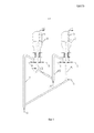
Фигура 2 представляет собой структурную схему псевдоожиженного слоя, создаваемого в плотной фазе, содержащего 4 вторичных реакционных зоны, по настоящему изобретению, где стрелки на виде в разрезе по A-A показывают направление потока катализатора между вторичными реакционными зонами;Figure 2 is a structural diagram of a dense phase fluidized bed containing 4 secondary reaction zones of the present invention, where the arrows in a sectional view along A-A indicate the direction of flow of the catalyst between the secondary reaction zones;
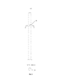
Фигура 3 представляет собой структурную схему псевдоожиженного слоя, создаваемого в плотной фазе, содержащего 4 вторичных регенерационных зоны, по настоящему изобретению, где стрелки на виде в разрезе по B-B показывают направление потока катализатора между вторичными регенерационными зонами;Figure 3 is a structural diagram of a dense phase fluidized bed containing 4 secondary regeneration zones of the present invention, where the arrows in a sectional view along B-B show the flow direction of the catalyst between the secondary regeneration zones;
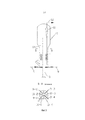
Фигура 4 представляет собой структурную схему разделительного устройства по настоящему изобретению;Figure 4 is a structural diagram of a separation device of the present invention;
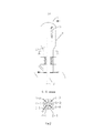
Фигура 5 представляет собой структурную схему устройства для контроля материального потока по настоящему изобретению.Figure 5 is a structural diagram of a device for controlling material flow according to the present invention.
Ссылочные обозначения фигур иллюстрируются следующим образом:The reference signs of the figures are illustrated as follows:
1: подающая линия реактора; 1-1: подающая разветвленная линия 1-вой вторичной реакционной зоны 1-2: подающая разветвленная линия 2-рой вторичной реакционной зоны; 1-3: подающая разветвленная линия 3-тьей вторичной реакционной зоны; 1-4: подающая разветвленная линия 4-той вторичной реакционной зоны; 2: реактор с псевдоожиженным слоем, создаваемым в плотной фазе,; 2-1: 1-вая вторичная реакционная зона; 2-2: 2-рая вторичная реакционная зона; 2-3: 3-тья вторичная реакционная зона; 2-4: 4-тая вторичная реакционная зона; 3: циклонный сепаратор; 4: линия готового материала; 5: разделительное устройство; 6: линия для паров воды; 7: подъемная труба; 8: газлифтная линия; 9: подающая линия регенератора; 9-1: подающая разветвленная линия 1-вой вторичной регенерационной зоны; 9-2: подающая разветвленная линия 2-рой вторичной регенерационной зоны; 9-3: подающая разветвленная линия 3-тьей вторичной регенерационной зоны; 9-4: подающая разветвленная линия 4-той вторичной регенерационной зоны; 10: регенератор с псевдоожиженным слоем, создаваемым в плотной фазе,; 10-1: 1-вая вторичная регенерационная зона; 10-2: 2-рая вторичная регенерационная зона; 10-3: 3-тья вторичная регенерационная зона; 10-4: 4-тая вторичная регенерационная зона; 11: циклонный сепаратор; 12: линия отработанного газа; 13: разделительное устройство; 14: линия для паров воды; 15: подъемная труба; 16: газлифтная линия; 17: устройство для контроля материального потока; 18: узел перетока материала; 19: разделительная пластина; 20: отверстие; 21: труба нисходящего потока материала; 22: нижний отбойник; 23: элемент теплообменника.1: reactor feed line; 1-1: supply branching line of the 1st secondary reaction zone 1-2: supply branching line of the 2nd secondary reaction zone; 1-3: supply branched line of the 3rd secondary reaction zone; 1-4: supply branched line of the 4th secondary reaction zone; 2: dense phase fluidized bed reactor; 2-1: 1st secondary reaction zone; 2-2: 2nd secondary reaction zone; 2-3: 3rd secondary reaction zone; 2-4: 4th secondary reaction zone; 3: cyclone separator; 4: finished material line; 5: separation device; 6: line for water vapor; 7: lift pipe 8: gas lift line; 9: regenerator feed line; 9-1: supply branched line of the 1st secondary regeneration zone; 9-2: supply branched line of the 2nd secondary regeneration zone; 9-3: supply branched line of the 3rd secondary regeneration zone; 9-4: supply branched line of the 4th secondary regeneration zone; 10: a fluidized bed regenerator generated in the dense phase; 10-1: 1st secondary regeneration zone; 10-2: 2nd secondary regeneration zone; 10-3: 3rd secondary regeneration zone; 10-4: 4th secondary regeneration zone; 11: cyclone separator; 12: exhaust gas line; 13: separation device; 14: line for water vapor; 15: lifting pipe 16: gas lift line; 17: device for controlling material flow; 18: material flow assembly; 19: dividing plate; 20: hole; 21: downward pipe material; 22: lower chipper; 23: heat exchanger element.
Описание предпочтительных вариантов осуществленияDescription of Preferred Embodiments
Для увеличения селективности по отношению к легким олефинам в способе получения легких олефинов с использованием кислородосодержащего соединения, настоящее изобретение предлагает способ получения легких олефинов с использованием кислородосодержащего соединения, включающий следующие стадии:To increase the selectivity to light olefins in a method for producing light olefins using an oxygen-containing compound, the present invention provides a method for producing light olefins using an oxygen-containing compound, comprising the following steps:
a) стадию, на которой исходный материал, содержащий кислородосодержащее соединение, вводится параллельно из n подающих разветвленных линий в 1-вую - n-ную вторичные реакционные зоны в реактор с псевдоожиженным слоем, создаваемым в плотной фазе, и вступает в контакт с катализатором для генерирования потока, содержащего продукт легких олефинов и отработанного катализатора, где указанный катализатор последовательно проходит через 1-вую - n-ную вторичные реакционные зоны, при этом содержание углерода в нем постепенно увеличивается, и где указанный реактор с псевдоожиженным слоем, создаваемым в плотной фазе, разделяется устройством для контроля материального потока на n вторичных реакционных зон;a) a stage in which a starting material containing an oxygen-containing compound is introduced in parallel from n supplying branched lines to the 1st to nth secondary reaction zones into the dense-phase fluidized bed reactor and comes into contact with the catalyst to generate the stream containing the product of light olefins and spent catalyst, where the specified catalyst sequentially passes through the 1st - nth secondary reaction zones, while the carbon content in it gradually increases, and where indicated a dense-phase fluidized bed reactor is separated by a material flow control device into n secondary reaction zones;
b) стадию, на которой поток, содержащий продукт легких олефинов, вытекающий из 1-вой - n-ной вторичных реакционных зон отделяется от отработанного катализатора, который он несет; указанный поток, содержащий продукт легких олефинов, проходит в секцию разделения продукта, и после разделения и очистки, получается продукт легких олефинов; выделенный отработанный катализатор проходит в n-ную вторичную реакционную зону иb) a stage in which a stream containing the product of light olefins flowing from the 1st to nth secondary reaction zones is separated from the spent catalyst that it carries; the specified stream containing the product of light olefins passes into the separation section of the product, and after separation and purification, the product of light olefins is obtained; the selected spent catalyst passes into the nth secondary reaction zone and
c) стадию, на которой отработанный катализатор, вытекающий из n-ной вторичной реакционной зоны, после отделения и подъема, проходит в регенератор с псевдоожиженным слоем, создаваемым в плотной фазе, для регенерации; указанный отработанный катализатор последовательно проходит через 1-вую - m-ную вторичные регенерационные зоны; регенерирующая среда вводится параллельно из m подающих разветвленных линий регенерационных зон в 1-вую - m-ную вторичные регенерационные зоны; отработанный катализатор вступает в контакт с регенерирующей средой, при этом содержание углерода в нем постепенно уменьшается; после завершения регенерации, катализатор возвращается обратно в 1-вую вторичную реакционную зону посредством разделения и подъема; где регенератор с псевдоожиженным слоем, создаваемым в плотной фазе, разделяется устройством для контроля материального потока на m вторичных регенерационных зон;c) a stage in which the spent catalyst flowing out of the nth secondary reaction zone, after separation and recovery, passes to a fluidized bed regenerator in the dense phase for regeneration; said spent catalyst sequentially passes through the 1st — mth secondary regeneration zones; the regenerating medium is introduced in parallel from m supplying branched lines of regeneration zones to the 1st — mth secondary regeneration zones; the spent catalyst comes into contact with the regenerating medium, while the carbon content in it gradually decreases; after completion of regeneration, the catalyst is returned back to the first secondary reaction zone by separation and recovery; where a fluidized bed regenerator created in the dense phase is separated by a material flow control device into m secondary regeneration zones;
где n≥2, предпочтительно, 8≥n≥3; m≥2, предпочтительно, 8≥m≥3.where n≥2, preferably 8≥n≥3; m≥2, preferably 8≥m≥3.
Предпочтительно, в реакторе с псевдоожиженным слоем, создаваемым в плотной фазе, видимая линейная скорость газа в устройстве для контроля материального потока равна или меньше, чем минимальная скорость псевдоожижения катализатора.Preferably, in a dense-phase fluidized bed reactor, the apparent linear velocity of the gas in the material flow control device is equal to or less than the minimum catalyst fluidization rate.
Предпочтительно, в регенераторе с псевдоожиженным слоем, создаваемым в плотной фазе, видимая линейная скорость газа в устройстве для контроля материального потока равна или меньше, чем минимальная скорость псевдоожижения катализатора.Preferably, in a dense-phase fluidized bed regenerator, the apparent linear gas velocity in the material flow control device is equal to or less than the minimum catalyst fluidization rate.
Предпочтительно, катализатор содержит молекулярное сито SAPO-34.Preferably, the catalyst comprises an SAPO-34 molecular sieve.
Предпочтительно, условия реакции в реакционной зоне в псевдоожиженном слое плотной фазы являются следующими: видимая линейная скорость газа составляет 0,1-1,5 м/сек, температура реакции составляет 400-550°C, плотность слоя составляет 200-1200 кг/м3; средняя величина отложения углерода катализатора в 1-вой вторичной реакционной зоне составляет 0,5-3% масс, а средняя величина отложения углерода катализатора в n-ной вторичной реакционной зоне составляет 7-10% масс.Preferably, the reaction conditions in the reaction zone in the fluidized bed of the dense phase are as follows: the apparent linear velocity of the gas is 0.1-1.5 m / s, the reaction temperature is 400-550 ° C, the density of the layer is 200-1200 kg / m 3 ; the average value of the carbon deposition of the catalyst in the 1st secondary reaction zone is 0.5-3% of the mass, and the average value of the carbon deposition of the catalyst in the nth secondary reaction zone is 7-10% of the mass.
Предпочтительно, условия реакции в регенерационной зоне в псевдоожиженном слое плотной фазы являются следующими: видимая линейная скорость газа составляет 0,1-1,5 м/сек, температура регенерации составляет 500-700°C, а плотность слоя составляет 200-1200 кг/м3; средняя величина отложения углерода катализатора последовательно уменьшается в зонах от 1-вой до m-ной вторичной регенерационной зоны, средняя величина отложения углерода катализатора в 1-вой вторичной регенерационной зоне составляет 3-10% масс, а средняя величина отложения углерода катализатора в m-ой вторичной регенерационной зоне составляет 0-3% масс.Preferably, the reaction conditions in the regeneration zone in the fluidized bed of the dense phase are as follows: the apparent linear velocity of the gas is 0.1-1.5 m / s, the regeneration temperature is 500-700 ° C, and the density of the layer is 200-1200 kg / m 3 ; the average amount of carbon deposition of the catalyst successively decreases in zones from the 1st to the m-th secondary regeneration zone, the average amount of carbon deposition of the catalyst in the 1st secondary regeneration zone is 3-10% of the mass, and the average amount of deposition of catalyst carbon in the m the secondary regeneration zone is 0-3% of the mass.
Предпочтительно, кислородосодержащее соединение представляет собой метанол и/или простой диметиловый эфир; легкий олефин представляет собой любое соединение из этилена, пропилена или бутилена или их смесь; регенерирующая среда представляет собой любую среду из воздуха, воздуха, обедненного кислородом, или паров воды, или их смесь.Preferably, the oxygen-containing compound is methanol and / or dimethyl ether; a light olefin is any compound of ethylene, propylene or butylene, or a mixture thereof; a regenerating medium is any medium of air, oxygen depleted air, or water vapor, or a mixture thereof.
Техническое решение, предлагаемое в настоящем изобретение, может дополнительно включать:The technical solution proposed in the present invention may further include:
(1) создание реактора с псевдоожиженным слоем, создаваемым в плотной фазе, содержащего реакционную зону, зону разделения газ - твердые продукты и разделительную зону, реакционная зона разделяется устройством для контроля материального потока на n вторичных реакционных зон, где n≥2;(1) creating a fluidized-bed reactor containing a reaction zone, a gas-solid separation zone and a separation zone, the reaction zone is divided by a device for controlling material flow into n secondary reaction zones, where n≥2;
(2) создание регенератора с псевдоожиженным с псевдоожиженным слоем, создаваемым в плотной фазе, содержащего регенерационную зону, зону разделения газ - твердые продукты и разделительную зону, регенерационная зона разделяется устройством для контроля материального потока на m вторичных регенерационных зон, где m≥2.(2) the creation of a fluidized bed fluidized bed regenerator created in a dense phase containing a regeneration zone, a gas-solid products separation zone and a separation zone, the regeneration zone is divided by a device for controlling the material flow into m secondary regeneration zones, where m≥2.
Предпочтительно, исходный материал, содержащий кислородосодержащее соединение, вводится в реактор с псевдоожиженным слоем, создаваемым в плотной фазе, и вступает в контакт с регенерированным катализатором, в результате чего получается продукт, содержащий легкий олефин, и углеродсодержащий отработанный катализатор, при этом регенерированный катализатор последовательно проходит через 1-вую - n-ную вторичные реакционные зоны, при этом содержание углерода в нем постепенно увеличивается.Preferably, the starting material containing the oxygen-containing compound is introduced into the dense-phase fluidized bed reactor and comes into contact with the regenerated catalyst, resulting in a product containing a light olefin and a carbon-containing spent catalyst, whereby the regenerated catalyst passes sequentially through the first - the nth secondary reaction zones, while the carbon content in it gradually increases.
Предпочтительно, посредством разделения и подъема, отработанный катализатор, вытекающий из n-ной вторичной реакционной зоны, проходит в регенератор с псевдоожиженным слоем, создаваемым в плотной фазе, для регенерации, отработанный катализатор последовательно проходит через 1-вую - m-ную вторичные регенерационные зоны и вступает в контакт с регенерирующей средой, при этом содержание углерода в нем постепенно уменьшается, а затем катализатор возвращается обратно в 1-вую вторичную реакционную зону посредством разделения и подъема.Preferably, by separation and recovery, the spent catalyst flowing out of the nth secondary reaction zone passes into a dense phase fluidized bed regenerator for regeneration, the spent catalyst sequentially passes through the first - mth secondary regeneration zones and comes into contact with the regenerating medium, while the carbon content in it gradually decreases, and then the catalyst is returned back to the first secondary reaction zone by separation and recovery.
Предпочтительно, поток продукта легких олефинов проходит в секцию разделения после отделения от отработанного катализатора, а выделенный отработанный катализатор проходит в n-ную вторичную реакционную зону.Preferably, the product stream of light olefins passes into the separation section after separation from the spent catalyst, and the separated spent catalyst passes into the nth secondary reaction zone.
В конкретном варианте осуществления, схема получения легкого олефина с использованием кислородосодержащего соединения по настоящему изобретению является такой, как показано на Фиг.1. Исходный материал, содержащий кислородосодержащее соединение, вводится из подающей линии реактора (1) и ее разветвленных линий (1-1, ……, 1-n) параллельно во вторичные реакционные зоны (2-1, ……, 2-n) в реакторе с псевдоожиженным слоем, создаваемым в плотной фазе, (2), и вступает в контакт с катализатором, содержащим молекулярное сито SAPO-34, для генерирования газофазного потока продукта и отработанного катализатора. Газофазный поток продукта и содержащийся отработанный катализатор проходят в циклонный сепаратор (3), где газофазный поток продукта протекает через выход циклонного сепаратора и линию (4) готового материала и поступает в следующую далее секцию разделения, содержащийся отработанный катализатор проходит в n-ную вторичную реакционную зону (2-n) через опускную трубу циклонного сепаратора; регенерированный катализатор из регенератора (10) с псевдоожиженным с псевдоожиженным слоем, создаваемым в плотной фазе, проходит в реактор (2) с псевдоожиженным слоем, создаваемым в плотной фазе, через разделительное устройство (13) и подъемную трубу (15), где нижняя часть разделительного устройства (13) соединяется с линией (14) для паров воды, и нижняя часть подъемной трубы (15) соединяется с газлифтной линией (16); регенерированный катализатор последовательно проходит через 1-вую - n-ную вторичные реакционные зоны (2-1, ……, 2-n) в реакторе с псевдоожиженным слоем, создаваемым в плотной фазе, (2), и формирует отработанный катализатор после отложения углерода; регенерирующая среда вводится из подающей линии (9) регенератора и его разветвленных линий (9-1, ……, 9-m) во вторичные регенерационные зоны (10-1, ……, 10-m) в регенераторе (10) с псевдоожиженным слоем, создаваемым в плотной фазе, и вступает в контакт с отработанным катализатором с генерированием отработанных газов и регенерированного катализатора после коксования, а затем отработанные газы и содержащийся регенерированный катализатор проходят в циклонный сепаратор (11), из которого отработанные газы проходят в секцию обработки хвостовых газов через выход циклонного сепаратора и линию (12) отработанных газов, и удаляются после обработки, а содержащийся регенерированный катализатор проходит в m-ную вторичную регенерационную зону (10-m) через опускную трубу циклонного сепаратора. Отработанный катализатор из реактора (2) с псевдоожиженным слоем, создаваемым в плотной фазе, проходит в регенератор (10) с псевдоожиженным слоем, создаваемым в плотной фазе, через разделительное устройство (5) и подъемную трубу (7), где нижняя часть разделительного устройства (5) соединяется с линией (6) для паров воды, а нижняя часть подъемной трубы (7) соединяется с газлифтной линией (8). В регенераторе (10) с псевдоожиженным слоем, создаваемым в плотной фазе, отработанный катализатор последовательно проходит через зоны от 1-вой до m-ой вторичных регенерационных зон (10-1, ……, 10-m) и формирует регенерированный катализатор после коксования.In a specific embodiment, a scheme for producing a light olefin using an oxygen-containing compound of the present invention is as shown in FIG. The source material containing the oxygen-containing compound is introduced from the reactor feed line (1) and its branched lines (1-1, ........, 1-n) in parallel into the secondary reaction zones (2-1, .......2-n) in the reactor with a fluidized bed created in the dense phase (2), and comes into contact with a catalyst containing an SAPO-34 molecular sieve to generate a gas phase product stream and spent catalyst. The gas-phase product stream and the spent catalyst contained pass into the cyclone separator (3), where the gas-phase product stream flows through the cyclone separator outlet and the finished material line (4) and enters the next separation section, the spent catalyst passes into the nth secondary reaction zone (2-n) through the downcomer of the cyclone separator; the regenerated catalyst from the regenerator (10) with the fluidized bed created in the dense phase passes into the reactor (2) with the fluidized bed created in the dense phase through the separation device (13) and the riser pipe (15), where the lower part of the separation the device (13) is connected to a line (14) for water vapor, and the lower part of the riser pipe (15) is connected to a gas-lift line (16); the regenerated catalyst passes sequentially through the first - n-th secondary reaction zones (2-1, ..., 2-n) in the fluidized-bed reactor created in the dense phase (2), and forms the spent catalyst after carbon deposition; the regenerating medium is introduced from the supply line (9) of the regenerator and its branched lines (9-1, ........ 9-m) into the secondary regeneration zones (10-1, ....... 10-m) in the regenerator (10) with a fluidized bed created in the dense phase and comes into contact with the spent catalyst to generate exhaust gases and regenerated catalyst after coking, and then the exhaust gases and the contained regenerated catalyst pass into a cyclone separator (11), from which the exhaust gases pass to the tail gas treatment section through h the outlet of the cyclone separator and the exhaust gas line (12), and are removed after treatment, and the contained regenerated catalyst passes into the m-th secondary regeneration zone (10-m) through the downcomer of the cyclone separator. The spent catalyst from the reactor (2) with the fluidized bed created in the dense phase passes into the regenerator (10) with the fluidized bed created in the dense phase through the separation device (5) and the lifting pipe (7), where the lower part of the separation device ( 5) is connected to the line (6) for water vapor, and the lower part of the lifting pipe (7) is connected to the gas-lift line (8). In a fluidized bed regenerator (10) created in the dense phase, the spent catalyst successively passes through the zones from the 1st to the mth secondary regeneration zones (10-1, ... ... 10-m) and forms the regenerated catalyst after coking.
В более конкретном варианте осуществления, структурная схема реактора с псевдоожиженным слоем, создаваемым в плотной фазе, содержащего 4 вторичные реакционные зоны по настоящему изобретению, является такой, как показано на Фиг.2. Три устройства (17) для контроля материальных потоков и один отбойник предусматриваются по вертикали для разделения реакционной зоны псевдоожиженным слоем, создаваемым в плотной фазе на 4 вторичных реакционных зоны. Катализатор последовательно проходит через 1-вую - 4-тую вторичные реакционные зоны, а затем проходит в разделительное устройство.In a more specific embodiment, a block diagram of a dense phase fluidized bed reactor containing 4 secondary reaction zones of the present invention is as shown in FIG. 2. Three devices (17) for controlling material flows and one chipper are provided vertically to separate the reaction zone with a fluidized bed created in the dense phase into 4 secondary reaction zones. The catalyst sequentially passes through the 1st to 4th secondary reaction zones, and then passes to the separation device.
В более конкретном варианте осуществления, структурная схема регенератора с псевдоожиженным слоем, создаваемым в плотной фазе, содержащего 4 вторичных регенерационных зоны по настоящему изобретению, являются такой, как показано на Фиг.3. Предусматриваются три устройства (17) для контроля материальных потоков и один отбойник по вертикали для разделения регенерационной зоны на 4 вторичных регенерационных зоны. Катализатор последовательно проходит через 1-вую - 4-тую вторичные регенерационные зоны, а затем проходит в разделительное устройство.In a more specific embodiment, a block diagram of a dense-phase fluidized bed regenerator containing 4 secondary regeneration zones of the present invention is as shown in FIG. 3. There are three devices (17) for controlling material flows and one vertical chipper for dividing the regeneration zone into 4 secondary regeneration zones. The catalyst sequentially passes through the 1st - 4th secondary regeneration zones, and then passes into the separation device.
В более конкретном варианте осуществления, структурная схема разделительного устройства по настоящему изобретению является такой, как показано на Фиг.4. Отверстие на стенке трубы на верхней части разделительного устройства представляет собой узел (18) перетока материала между n-ной вторичной реакционной зоной (или m-ой вторичной регенерационной зоной) и разделительным устройством.In a more specific embodiment, the block diagram of the separation device of the present invention is as shown in FIG. 4. The hole on the pipe wall at the top of the separation device is a material flow unit (18) between the nth secondary reaction zone (or mth secondary regeneration zone) and the separation device.
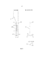
В более конкретном варианте осуществления, структурная схема устройства для контроля материального потока по настоящему изобретению является такой, как показано на Фиг.5. Устройство (17) для контроля материального потока состоит из разделительной пластины (19), отверстия (20), трубы (21) для нисходящего потока материала, нижнего отбойника (22) и элемента теплообменника (23). Катализатор проходит в трубу для нисходящего потока материала из верхней части трубы для нисходящего потока, где видимая линейная скорость газа равна или меньше чем минимальная скорость псевдоожижения, катализатор в трубе для нисходящего потока материала находится в состоянии набитой плотной фазы, и формируется движущая сила потока материала, чтобы заставить катализатор протекать в следующую вторичную реакционную зону (или регенерационную зону) через отверстие. Спиральная структура может быть использована в качестве элемента теплообменника, который фиксируется на разделительной пластине.In a more specific embodiment, the structural diagram of the material flow control device of the present invention is as shown in FIG. 5. The device (17) for controlling the material flow consists of a separation plate (19), an opening (20), a pipe (21) for a downward flow of material, a lower baffle (22) and a heat exchanger element (23). The catalyst passes into the pipe for the downward flow of material from the top of the pipe for the downward flow, where the apparent linear velocity of the gas is equal to or less than the minimum fluidization rate, the catalyst in the pipe for the downward flow of material is in a state of packed dense phase, and the driving force of the material flow is formed, to cause the catalyst to flow into the next secondary reaction zone (or regeneration zone) through the hole. The spiral structure can be used as an element of the heat exchanger, which is fixed on the separation plate.
Предпочтительно, в указанных выше технических решениях, видимая линейная скорость газа в реакционной зоне псевдоожиженным слоем, создаваемым в плотной фазе, составляет 0,1-1,5 м/сек; видимая линейная скорость газа в регенерационной зоне псевдоожиженным слоем, создаваемым в плотной фазе, составляет 0,1-1,5 м/сек; видимая линейная скорость газа в устройстве для контроля материального потока равна или меньше чем минимальная скорость псевдоожижения катализатора; катализатор включает молекулярное сито SAPO-34; предусматривается вход для исходных материалов в нижней части реакционной зоны, и исходные материалы содержат метанол, простой диметиловый эфир, и тому подобное; разделительная среда в разделительном устройстве содержит пары воды; вход для регенерирующей среды предусматривается в нижней части регенерационной зоны, и регенерирующая среда включает воздух, воздух, обедненный кислородом, пары воды, и тому подобное; температура реакции в реакционной зоне составляет 400-550°C, плотность слоя составляет 200-1200 кг/м3, средняя величина отложения углерода на катализаторе последовательно увеличивается в зонах от 1-вой до n-ной вторичной реакционной зоны, средняя величина отложения углерода в 1-вой вторичной реакционной зоне составляет 0,5-3% масс, средняя величина отложения углерода в n-ной вторичной реакционной зоне составляет 7-10% масс; температура реакции в регенерационной зоне составляет 500-700°C, плотность слоя составляет 200-1200 кг/м3, средняя величина отложения углерода на катализаторе последовательно уменьшается в зонах от 1-вой до m-ной вторичной регенерационной зоны, средняя величина отложения углерода в 1-вой вторичной регенерационной зоне составляет 3-10% масс, а средняя величина отложения углерода в m-ной вторичной регенерационной зоне составляет 0-3% масс. При использовании способа по настоящему изобретению может быть достигнута цель контроля величина отложения углерода на катализаторе, улучшения однородности содержания углерода и повышения селективности по отношению к легким олефинам. Следовательно, оно имеет значительные технические преимущества и является полезным при промышленном получении легких олефинов.Preferably, in the above technical solutions, the apparent linear velocity of the gas in the reaction zone of the fluidized bed created in the dense phase is 0.1-1.5 m / s; the apparent linear velocity of the gas in the regeneration zone of the fluidized bed created in the dense phase is 0.1-1.5 m / s; the apparent linear gas velocity in the material flow control device is equal to or less than the minimum catalyst fluidization rate; the catalyst includes an SAPO-34 molecular sieve; an input is provided for the starting materials in the lower part of the reaction zone, and the starting materials contain methanol, dimethyl ether, and the like; the separation medium in the separation device contains water vapor; an inlet for the regeneration medium is provided at the bottom of the regeneration zone, and the regeneration medium includes air, oxygen depleted air, water vapor, and the like; the reaction temperature in the reaction zone is 400-550 ° C, the density of the layer is 200-1200 kg / m 3 , the average carbon deposition on the catalyst gradually increases in the zones from the 1st to the n-th secondary reaction zone, the average carbon deposition in The 1st secondary reaction zone is 0.5-3% of the mass, the average carbon deposition in the n-th secondary reaction zone is 7-10% of the mass; the reaction temperature in the regeneration zone is 500-700 ° C, the layer density is 200-1200 kg / m 3 , the average carbon deposition on the catalyst is successively reduced in the zones from the 1st to the mth secondary regeneration zone, the average carbon deposition in The 1st secondary regeneration zone is 3-10% of the mass, and the average carbon deposition in the mth secondary regeneration zone is 0-3% of the mass. By using the method of the present invention, the goal of controlling the amount of carbon deposition on the catalyst, improving the uniformity of the carbon content and increasing the selectivity to light olefins can be achieved. Therefore, it has significant technical advantages and is useful in the industrial production of light olefins.
Для лучшего иллюстрирования настоящего изобретения и облегчения понимания технического решения по настоящему изобретению, приводятся следующие иллюстративные, но не ограничивающие примеры по настоящему изобретению.To better illustrate the present invention and facilitate understanding of the technical solution of the present invention, the following illustrative, but not limiting examples of the present invention are provided.
Пример 1Example 1
Предусматриваются 4 вторичных реакционных зоны в реакторе с псевдоожиженным слоем, создаваемым в плотной фазе, и предусматриваются 4 вторичных регенерационных зоны в регенераторе с псевдоожиженным слоем, создаваемым в плотной фазе. Исходный материал, содержащий кислородосодержащее соединение, проходит в реактор с псевдоожиженным слоем, создаваемым в плотной фазе, и вступает в контакт с катализатором, содержащим молекулярное сито SAPO-34, с генерированием газофазного потока продукта и отработанного катализатора. Газофазный материал и содержащийся отработанный катализатор проходят в циклонный сепаратор. Газофазный поток продукта проходит в следующую далее секцию разделения через выход циклонного сепаратора, а содержащийся отработанный катализатор проходит в 4-тую вторичную реакционную зону через опускную трубу циклонного сепаратора. Регенерированный катализатор проходит в реактор с псевдоожиженным слоем, создаваемым в плотной фазе, через разделительное устройство и подъемную трубу, а впоследствии проходит через 1-вую - 4-тую вторичные реакционные зоны, с формированием отработанного катализатора после отложения углерода. Затем отработанный катализатор проходит в регенератор с псевдоожиженным слоем, создаваемым в плотной фазе, через разделительное устройство и подъемную трубу, и после этого проходит через 1-вую - 4-тую вторичные регенерационные зоны, с формированием регенерированного катализатора после коксования. Условия реакции в реакторе с псевдоожиженным слоем, создаваемым в плотной фазе, являются следующими: температура реакции составляет 400°C, линейная скорость газа составляет 0,3 м/сек, плотность слоя составляет 1000 кг/м3, средняя величина отложения углерода в 1-вой вторичной реакционной зоне составляет 2% масс, средняя величина отложения углерода во 2-рой вторичной реакционной зоне составляет 6% масс, средняя величина отложения углерода в 3-тьей вторичной реакционной зоне составляет 8% масс, а средняя величина отложения углерода в 4-той вторичной реакционной зоне составляет 10% масс; условия реакции в регенераторе с псевдоожиженным слоем, создаваемым в плотной фазе, являются следующими: температура реакции составляет 500°C, линейная скорость газа составляет 0,3 м/сек, плотность слоя составляет 1000 кг/м3, средняя величина отложения углерода в 1-вой вторичной регенерационной зоне составляет 7% масс, средняя величина отложения углерода во 2-рой вторичной регенерационной зоне составляет 4% масс, средняя величина отложения углерода в 3-тьей вторичной регенерационной зоне составляет 2% масс, а средняя величина отложения углерода в 4-той вторичной регенерационной зоне составляет 1% масс. Продукт реакции анализируют с помощью on-line газовой хроматографии, и выход легких олефинов по отношению к углероду составляет 91,1% масс.There are 4 secondary reaction zones in the dense phase fluidized bed reactor, and 4 secondary regeneration zones in the dense phase fluidized bed regenerator. The starting material containing the oxygen-containing compound passes into the fluidized-bed reactor created in the dense phase and comes into contact with the catalyst containing the SAPO-34 molecular sieve, generating a gas-phase product stream and spent catalyst. The gas phase material and the spent catalyst contained pass into a cyclone separator. The gas-phase product stream passes to the next separation section through the outlet of the cyclone separator, and the spent spent catalyst passes into the fourth secondary reaction zone through the downcomer of the cyclone separator. The regenerated catalyst passes into the dense-phase fluidized bed reactor through a separation device and a riser, and subsequently passes through the first to fourth secondary reaction zones, with the formation of spent catalyst after carbon deposition. Then, the spent catalyst passes into the regenerator with a fluidized bed created in the dense phase through the separation device and the riser pipe, and then passes through the 1st - 4th secondary regeneration zones, with the formation of the regenerated catalyst after coking. The reaction conditions in the fluidized bed reactor created in the dense phase are as follows: the reaction temperature is 400 ° C, the linear velocity of the gas is 0.3 m / s, the density of the layer is 1000 kg / m 3 , the average carbon deposition is 1- the second secondary reaction zone is 2% of the mass, the average carbon deposition in the second secondary reaction zone is 6% of the mass, the average carbon deposition in the third secondary reaction zone is 8% of the mass, and the average carbon deposition in the 4th secondary eaktsionnoy zone is 10% by weight; the reaction conditions in the fluidized bed regenerator created in the dense phase are as follows: the reaction temperature is 500 ° C, the linear gas velocity is 0.3 m / s, the density of the layer is 1000 kg / m 3 , the average carbon deposition is 1- the second secondary regeneration zone is 7% of the mass, the average carbon deposition in the second secondary regeneration zone is 4% of the mass, the average carbon deposition in the third secondary regeneration zone is 2% of the mass, and the average carbon deposition in the 4th secondary regeneration zone is 1% of the mass. The reaction product is analyzed using on-line gas chromatography, and the yield of light olefins relative to carbon is 91.1% of the mass.
Пример 2Example 2
Предусматриваются 3 вторичных реакционных зоны в реакторе с псевдоожиженным слоем, создаваемым в плотной фазе, и предусматриваются 2 вторичных регенерационных зоны в регенераторе с псевдоожиженным слоем, создаваемым в плотной фазе. Исходный материал, содержащий кислородосодержащее соединение, проходит в реактор с псевдоожиженным слоем, создаваемым в плотной фазе, и вступает в контакт с катализатором, содержащим молекулярное сито SAPO-34, с генерированием газофазного потока продукта и отработанного катализатора. Газофазный материал и содержащийся отработанный катализатор проходят в циклонный сепаратор, газофазный поток продукта проходит в следующую далее секцию разделения через выход циклонного сепаратора, и содержащийся отработанный катализатор проходит в 3-тью вторичную реакционную зону через опускную трубу циклонного сепаратора. Регенерированный катализатор проходит в реактор с псевдоожиженным слоем, создаваемым в плотной фазе, через разделительное устройство и подъемную трубу, а впоследствии проходит через 1-вую - 3-тью вторичные реакционные зоны, с формированием отработанного катализатора после отложения углерода. Отработанный катализатор проходит в регенератор с псевдоожиженным слоем, создаваемым в плотной фазе, через разделительное устройство и подъемную трубу, а после этого проходит через 1-вую - 2-рую вторичные регенерационные зоны, с формированием регенерированного катализатора после коксования. Условия реакции в реакторе с псевдоожиженным слоем, создаваемым в плотной фазе, являются следующими: температура реакции составляет 450°C, линейная скорость газа составляет 0,5 м/сек, плотность слоя составляет 900 кг/м3, средняя величина отложения углерода в 1-вой вторичной реакционной зоне составляет 3% масс, средняя величина отложения углерода во 2-рой вторичной реакционной зоне составляет 7% масс, а средняя величина отложения углерода в 3-тьей вторичной реакционной зоне составляет 9% масс; условия реакции в регенераторе с псевдоожиженным слоем, создаваемым в плотной фазе, являются следующими: температура реакции составляет 600°C, линейная скорость газа составляет 0,7 м/сек, плотность слоя составляет 700 кг/м3, средняя величина отложения углерода в 1-вой вторичной регенерационной зоне составляет 4% масс, а средняя величина отложения углерода во 2-рой вторичной реакционной зоне составляет 2% масс. Продукт реакции анализируют с помощью on-line газовой хроматографии, и выход легких олефинов по отношению к углероду составляет 90,5% масс.There are 3 secondary reaction zones in the dense phase fluidized bed reactor and 2 secondary regeneration zones in the dense phase fluidized bed regenerator. The starting material containing the oxygen-containing compound passes into the fluidized-bed reactor created in the dense phase and comes into contact with the catalyst containing the SAPO-34 molecular sieve, generating a gas-phase product stream and spent catalyst. The gas-phase material and the spent catalyst contained pass into the cyclone separator, the gas-phase product stream passes to the next separation section through the outlet of the cyclone separator, and the spent catalyst passes into the third secondary reaction zone through the downcomer of the cyclone separator. The regenerated catalyst passes into the dense-phase fluidized-bed reactor through a separation device and a riser, and subsequently passes through the first to 3 secondary reaction zones, with the formation of spent catalyst after carbon deposition. The spent catalyst passes into the regenerator with a fluidized bed created in the dense phase, through the separation device and the riser, and then passes through the 1st - 2nd secondary regeneration zones, with the formation of the regenerated catalyst after coking. The reaction conditions in the fluidized bed reactor created in the dense phase are as follows: the reaction temperature is 450 ° C, the linear velocity of the gas is 0.5 m / s, the density of the layer is 900 kg / m 3 , the average carbon deposition is 1- the second secondary reaction zone is 3% of the mass, the average carbon deposition in the second secondary reaction zone is 7% of the mass, and the average carbon deposition in the third secondary reaction zone is 9% of the mass; the reaction conditions in the fluidized bed regenerator created in the dense phase are as follows: the reaction temperature is 600 ° C, the linear gas velocity is 0.7 m / s, the density of the layer is 700 kg / m 3 , the average carbon deposition is 1- the second secondary regeneration zone is 4% of the mass, and the average carbon deposition in the second secondary reaction zone is 2% of the mass. The reaction product is analyzed using on-line gas chromatography, and the yield of light olefins relative to carbon is 90.5% of the mass.
Пример 3Example 3
Предусматриваются 6 вторичных реакционных зоны в реакторе с псевдоожиженным слоем, создаваемым в плотной фазе, и предусматриваются 5 вторичных регенерационных зон в регенераторе с псевдоожиженным слоем, создаваемым в плотной фазе. Исходный материал, содержащий кислородосодержащее соединение, проходит в реактор с псевдоожиженным слоем, создаваемым в плотной фазе, и вступает в контакт с катализатором, содержащим молекулярное сито SAPO-34, с генерированием газофазного потока продукта и отработанного катализатора. Газофазный материал и содержащийся отработанный катализатор проходят в циклонный сепаратор, газофазный поток продукта проходит в следующую далее секцию разделения через выход циклонного сепаратора, и содержащийся отработанный катализатор проходит в 6-тую вторичную реакционную зону через опускную трубу циклонного сепаратора. Регенерированный катализатор проходит в реактор с псевдоожиженным слоем, создаваемым в плотной фазе, через разделительное устройство и подъемную трубу, а впоследствии проходит через 1-вую - 6-тую вторичные реакционные зоны, с формированием отработанного катализатора после отложения углерода. Отработанный катализатор дополнительно проходит в регенератор с псевдоожиженным слоем, создаваемым в плотной фазе, через разделительное устройство и подъемную трубу, а после этого проходит через 1-вую - 5-тую вторичные регенерационные зоны, с формированием регенерированного катализатора после коксования. Условия реакции в реакторе с псевдоожиженным слоем, создаваемым в плотной фазе, являются следующими: температура реакции составляет 480°C, линейная скорость газа составляет 0,7 м/сек, плотность слоя составляет 700 кг/м3, средняя величина отложения углерода в 1-вой вторичной реакционной зоне составляет 1% масс, средняя величина отложения углерода во 2-рой вторичной реакционной зоне составляет 3% масс, средняя величина отложения углерода в 3-тьей вторичной реакционной зоне составляет 4% масс, средняя величина отложения углерода в 4-той вторичной реакционной зоне составляет 5% масс, средняя величина отложения углерода в 5-той вторичной реакционной зоне составляет 6% масс, а средняя величина отложения углерода в 6-той вторичной реакционной зоне составляет 7% масс; условия реакции в регенераторе с псевдоожиженным слоем, создаваемым в плотной фазе, являются следующими: температура реакции составляет 650°C, линейная скорость газа составляет 1,0 м/сек, плотность слоя составляет 500 кг/м3, средняя величина отложения углерода в 1-вой вторичной регенерационной зоне составляет 5% масс, средняя величина отложения углерода во 2-рой вторичной реакционной зоне составляет 3% масс, средняя величина отложения углерода в 3-тьей вторичной регенерационной зоне составляет 2% масс, средняя величина отложения углерода в 4-той вторичной регенерационной зоне составляет 1% масс, а средняя величина отложения углерода в 5-той вторичной регенерационной зоне составляет 0,01% масс. Продукт реакции анализируют с помощью on-line газовой хроматографии, и выход легких олефинов по отношению к углероду составляет 91,4% масс.There are 6 secondary reaction zones in the dense phase fluidized bed reactor and 5 secondary regeneration zones in the dense phase fluidized bed regenerator. The starting material containing the oxygen-containing compound passes into the fluidized-bed reactor created in the dense phase and comes into contact with the catalyst containing the SAPO-34 molecular sieve, generating a gas-phase product stream and spent catalyst. The gas-phase material and the spent catalyst contained pass into the cyclone separator, the gas-phase product stream passes to the next separation section through the outlet of the cyclone separator, and the spent catalyst passes into the 6th secondary reaction zone through the downcomer of the cyclone separator. The regenerated catalyst passes into the dense-phase fluidized bed reactor through a separation device and a riser pipe, and subsequently passes through the first through sixth secondary reaction zones, with the formation of spent catalyst after carbon deposition. The spent catalyst additionally passes into the regenerator with a fluidized bed created in the dense phase, through the separation device and the riser pipe, and then passes through the 1st - 5th secondary regeneration zones, with the formation of the regenerated catalyst after coking. The reaction conditions in the fluidized bed reactor created in the dense phase are as follows: the reaction temperature is 480 ° C, the linear gas velocity is 0.7 m / s, the density of the layer is 700 kg / m 3 , the average carbon deposition is 1- the second secondary reaction zone is 1% of the mass, the average carbon deposition in the second secondary reaction zone is 3% of the mass, the average carbon deposition in the third secondary reaction zone is 4% of the mass, the average carbon deposition in the 4th secondary re ktsionnoy zone is 5% by weight, the average carbon deposition rate is 5-th secondary reaction zone is 6 mass%, and the average value of carbon deposition in 6 of the secondary reaction zone is 7% by weight; the reaction conditions in the fluidized bed regenerator created in the dense phase are as follows: the reaction temperature is 650 ° C, the linear gas velocity is 1.0 m / s, the density of the layer is 500 kg / m 3 , the average carbon deposition is 1- the second secondary regeneration zone is 5% of the mass, the average carbon deposition in the second secondary reaction zone is 3% of the mass, the average carbon deposition in the third secondary regeneration zone is 2% of the mass, the average carbon deposition in the 4th the secondary regeneration zone is 1% of the mass, and the average carbon deposition in the 5th secondary regeneration zone is 0.01% of the mass. The reaction product is analyzed using on-line gas chromatography, and the yield of light olefins relative to carbon is 91.4% of the mass.
Настоящее изобретение описано подробно выше, но настоящее изобретение не ограничивается конкретными вариантами осуществления, описанными в настоящем документе. Специалистам в данной области будет очевидно, что другие модификации и варианты могут быть осуществлены без отклонения от рамок настоящего изобретения. Рамки настоящего изобретения определяются прилагаемой формулой изобретения.The present invention has been described in detail above, but the present invention is not limited to the specific embodiments described herein. It will be apparent to those skilled in the art that other modifications and variations can be made without departing from the scope of the present invention. The scope of the present invention is defined by the attached claims.
Claims (15)
Applications Claiming Priority (1)
| Application Number | Priority Date | Filing Date | Title |
|---|---|---|---|
| PCT/CN2013/088388 WO2015081484A1 (en) | 2013-12-03 | 2013-12-03 | Method for preparing a light olefin using an oxygen-containing compound, and device for use thereof |
Publications (1)
| Publication Number | Publication Date |
|---|---|
| RU2635553C1 true RU2635553C1 (en) | 2017-11-14 |
Family
ID=53272719
Family Applications (1)
| Application Number | Title | Priority Date | Filing Date |
|---|---|---|---|
| RU2016125852A RU2635553C1 (en) | 2013-12-03 | 2013-12-03 | Method for obtaining light olefins using oxygen-containing compounds and device for its application |
Country Status (9)
| Country | Link |
|---|---|
| US (1) | US9718743B2 (en) |
| EP (1) | EP3078652B1 (en) |
| JP (1) | JP6199493B2 (en) |
| KR (1) | KR101864442B1 (en) |
| AU (1) | AU2013407175B2 (en) |
| DK (1) | DK3078652T3 (en) |
| RU (1) | RU2635553C1 (en) |
| SG (1) | SG11201604424YA (en) |
| WO (1) | WO2015081484A1 (en) |
Families Citing this family (12)
| Publication number | Priority date | Publication date | Assignee | Title |
|---|---|---|---|---|
| SG11201604429VA (en) * | 2013-12-03 | 2016-07-28 | Dalian Chemical Physics Inst | Method for preparing a light olefin using an oxygen-containing compound |
| JP6883100B2 (en) * | 2016-10-19 | 2021-06-09 | 中国科学院大▲連▼化学物理研究所Dalian Institute Of Chemical Physics,Chinese Academy Of Sciences | Turbulent fluidized bed reactors, equipment and methods for producing propylene and C4 hydrocarbons from oxygen-containing compounds |
| AU2016427079B2 (en) * | 2016-10-19 | 2019-10-31 | Dalian Institute Of Chemical Physics, Chinese Academy Of Sciences | Fast fluidized-bed reactor, device, and method using oxygen-containing compound for manufacturing propene or C4 hydrocarbon |
| JP6883099B2 (en) * | 2016-10-19 | 2021-06-09 | 中国科学院大▲連▼化学物理研究所Dalian Institute Of Chemical Physics,Chinese Academy Of Sciences | Method for Producing Hydrocarbons of Propylene and C4 and its Equipment |
| WO2019104655A1 (en) | 2017-11-30 | 2019-06-06 | 中国科学院大连化学物理研究所 | Molecular sieve-based catalyst modification apparatus, and method |
| CN109865530B (en) * | 2017-12-05 | 2021-12-21 | 中国科学院大连化学物理研究所 | Method for partially regenerating methanol-to-olefin catalyst and methanol-to-olefin method |
| SG11202005199TA (en) * | 2017-12-05 | 2020-07-29 | Dalian Inst Chemical Physics Cas | Method for partially regenerating methanol to olefin catalyst and methanol to olefin process |
| CN111054281B (en) * | 2018-10-17 | 2022-03-11 | 中国石油化工股份有限公司 | Catalyst fluidized bed reactor, reaction system and method using system |
| CN112705127B (en) * | 2019-10-24 | 2022-11-01 | 中国石油化工股份有限公司 | Reactor and method for producing low-carbon olefin |
| US11833502B2 (en) | 2020-10-16 | 2023-12-05 | Dalian Institute Of Chemical Physics, Chinese Academy Of Sciences | Coke control reactor, and device and method for preparing low-carbon olefins from oxygen-containing compound |
| JP7393114B2 (en) | 2020-10-16 | 2023-12-06 | 中国科学院大▲連▼化学物理研究所 | Fluidized bed reactor, equipment and applications |
| CN112851455A (en) * | 2021-01-18 | 2021-05-28 | 中国神华煤制油化工有限公司 | Method for preparing olefin from methanol |
Citations (3)
| Publication number | Priority date | Publication date | Assignee | Title |
|---|---|---|---|---|
| US2919241A (en) * | 1955-06-17 | 1959-12-29 | Kellogg M W Co | Conversion process and apparatus with plural adjacent stages and central stripping zone |
| FR2417336A1 (en) * | 1978-02-16 | 1979-09-14 | Melik Akhnazarov Talyat | Regenerating catalyst from hydrocarbon cracking - by oxidn. in fluidise beds with gas successively in parallel flow and in cross flow, minimising residual coke |
| EA200801961A1 (en) * | 2006-03-31 | 2009-04-28 | Эксонмобил Кемикэл Пейтентс Инк. | TURNING OXYGENATES UNDER HIGH PRESSURE AND HIGH PERFORMANCE WITH A CATALYST IMPACT CYCLE |
Family Cites Families (20)
| Publication number | Priority date | Publication date | Assignee | Title |
|---|---|---|---|---|
| US6023005A (en) * | 1997-07-03 | 2000-02-08 | Exxon Chemicals Patents Inc. | Process for converting oxygenates to olefins using molecular sieve catalysts comprising desirable carbonaceous deposits |
| US6166282A (en) | 1999-08-20 | 2000-12-26 | Uop Llc | Fast-fluidized bed reactor for MTO process |
| US7057083B2 (en) | 2003-11-12 | 2006-06-06 | Exxonmobil Chemical Patents Inc. | Catalyst pretreatment with C4-C7 olefins in an oxygenate to olefins reaction system |
| US7465845B2 (en) * | 2004-12-22 | 2008-12-16 | Exxonmobil Chemical Patents Inc. | Increasing ethylene and/or propylene production in an oxygenate to olefins reaction systems |
| CN101164687B (en) * | 2006-10-20 | 2010-05-12 | 中国石油化工股份有限公司 | Multi-reaction-area combination type reactor |
| CN101239870B (en) * | 2007-02-07 | 2011-08-17 | 中国石油化工股份有限公司 | Process for converting methanol or ethanol to preparing low-carbon olefins |
| CN101348404B (en) | 2007-07-18 | 2011-11-30 | 中国石油化工股份有限公司 | Method for improving ethylene and propene yield in methyl alcohol or dimethyl ether conversion process |
| CN101327445B (en) | 2008-06-12 | 2010-06-09 | 中国石油化工股份有限公司 | High-efficient regeneration method for preparing low carbon olefins catalyst from oxygen-containing compounds |
| CN102076636B (en) | 2008-06-25 | 2014-04-16 | 道达尔石油化学产品研究弗吕公司 | Process to make olefins from oxy-compound |
| CN101367700B (en) | 2008-09-18 | 2011-08-03 | 浙江大学 | Radially moving bed reactor for preparing propylene with oxygen-containing compound as raw material |
| CN101367694B (en) | 2008-09-18 | 2012-06-13 | 浙江大学 | Horizontal moving bed reactor for preparing propylene with oxygen-containing compound as raw material |
| CN101402538B (en) | 2008-11-21 | 2013-01-09 | 中国石油化工股份有限公司 | Method for improving yield of light olefins |
| CN102276406B (en) | 2010-06-11 | 2014-07-23 | 中国石油化工股份有限公司 | Method for increasing yield of propylene |
| CN102464535B (en) | 2010-11-17 | 2014-03-26 | 中国石油化工股份有限公司 | Method for producing low carbon olefin from methanol or dimethyl ether |
| RU2602888C2 (en) | 2011-05-12 | 2016-11-20 | Глатт Инженьертехник Гмбх | Device for continuous treatment of solid substances in apparatus with fluidised bed |
| CN102875289B (en) | 2011-07-12 | 2014-12-10 | 中国石油化工股份有限公司 | Method for preparing low-carbon olefins |
| CN102875291B (en) | 2011-07-12 | 2014-11-26 | 中国石油化工股份有限公司 | Method for producing low-carbon olefins from methanol |
| CN102875296B (en) | 2011-07-12 | 2015-01-07 | 中国石油化工股份有限公司 | Reaction unit for preparing low-carbon olefins |
| CN103193574B (en) | 2012-01-10 | 2015-01-07 | 中国石油化工股份有限公司 | On-stream method of methanol to light olefin reaction-regeneration device |
| SG11201604429VA (en) * | 2013-12-03 | 2016-07-28 | Dalian Chemical Physics Inst | Method for preparing a light olefin using an oxygen-containing compound |
-
2013
- 2013-12-03 US US15/100,834 patent/US9718743B2/en active Active
- 2013-12-03 KR KR1020167017518A patent/KR101864442B1/en active IP Right Grant
- 2013-12-03 RU RU2016125852A patent/RU2635553C1/en active
- 2013-12-03 JP JP2016535728A patent/JP6199493B2/en active Active
- 2013-12-03 AU AU2013407175A patent/AU2013407175B2/en not_active Ceased
- 2013-12-03 SG SG11201604424YA patent/SG11201604424YA/en unknown
- 2013-12-03 EP EP13898826.6A patent/EP3078652B1/en active Active
- 2013-12-03 DK DK13898826.6T patent/DK3078652T3/en active
- 2013-12-03 WO PCT/CN2013/088388 patent/WO2015081484A1/en active Application Filing
Patent Citations (3)
| Publication number | Priority date | Publication date | Assignee | Title |
|---|---|---|---|---|
| US2919241A (en) * | 1955-06-17 | 1959-12-29 | Kellogg M W Co | Conversion process and apparatus with plural adjacent stages and central stripping zone |
| FR2417336A1 (en) * | 1978-02-16 | 1979-09-14 | Melik Akhnazarov Talyat | Regenerating catalyst from hydrocarbon cracking - by oxidn. in fluidise beds with gas successively in parallel flow and in cross flow, minimising residual coke |
| EA200801961A1 (en) * | 2006-03-31 | 2009-04-28 | Эксонмобил Кемикэл Пейтентс Инк. | TURNING OXYGENATES UNDER HIGH PRESSURE AND HIGH PERFORMANCE WITH A CATALYST IMPACT CYCLE |
Also Published As
| Publication number | Publication date |
|---|---|
| AU2013407175B2 (en) | 2017-06-15 |
| WO2015081484A1 (en) | 2015-06-11 |
| US20160304412A1 (en) | 2016-10-20 |
| JP2017501989A (en) | 2017-01-19 |
| KR20160095024A (en) | 2016-08-10 |
| EP3078652B1 (en) | 2018-07-18 |
| SG11201604424YA (en) | 2016-07-28 |
| JP6199493B2 (en) | 2017-09-20 |
| KR101864442B1 (en) | 2018-06-04 |
| EP3078652A1 (en) | 2016-10-12 |
| US9718743B2 (en) | 2017-08-01 |
| EP3078652A4 (en) | 2017-06-07 |
| DK3078652T3 (en) | 2018-08-27 |
| AU2013407175A1 (en) | 2016-06-23 |
Similar Documents
| Publication | Publication Date | Title |
|---|---|---|
| RU2635553C1 (en) | Method for obtaining light olefins using oxygen-containing compounds and device for its application | |
| RU2636077C1 (en) | Reactive device for obtaining light olefins from methanol and/or dimethyl ether | |
| RU2632905C1 (en) | Method of producing light olefins by oxygen-containing compound | |
| JP2017504654A5 (en) | ||
| CN104672045B (en) | A kind of reaction unit for methanol and/or dimethyl ether low-carbon alkene | |
| RU2012129238A (en) | METHOD FOR TRANSFORMING HYDROCARBONS ON A SOLID CATALYST USING COMPOSITE REACTORS WITH MOVING LAYER | |
| CN104672040A (en) | Method and equipment for preparing low carbon olefin from oxygenated compounds | |
| JP2007063270A (en) | Method for producing lower olefin from methanol or dimethyl ether | |
| CN105218288B (en) | High-efficiency rapid gas-solid separation and settlement method for methanol-to-olefin | |
| CN112778069A (en) | Method and device for improving selectivity of low-carbon olefin prepared by converting oxygen-containing compound | |
| BR112016012646B1 (en) | METHOD FOR PREPARING LIGHT OLEFIN USING AN OXYGEN CONTAINING COMPOUND |