RU2632503C1 - Method of producing composite products with inner cavity by means of explosion welding - Google Patents
Method of producing composite products with inner cavity by means of explosion welding Download PDFInfo
- Publication number
- RU2632503C1 RU2632503C1 RU2016124568A RU2016124568A RU2632503C1 RU 2632503 C1 RU2632503 C1 RU 2632503C1 RU 2016124568 A RU2016124568 A RU 2016124568A RU 2016124568 A RU2016124568 A RU 2016124568A RU 2632503 C1 RU2632503 C1 RU 2632503C1
- Authority
- RU
- Russia
- Prior art keywords
- cavity
- layer
- forming element
- wall thickness
- product
- Prior art date
Links
- 238000003466 welding Methods 0.000 title claims abstract description 56
- 238000004880 explosion Methods 0.000 title claims abstract description 42
- 238000000034 method Methods 0.000 title claims abstract description 24
- 239000002131 composite material Substances 0.000 title claims abstract description 17
- 239000002360 explosive Substances 0.000 claims abstract description 46
- 239000010936 titanium Substances 0.000 claims abstract description 41
- 229910052719 titanium Inorganic materials 0.000 claims abstract description 40
- 239000010949 copper Substances 0.000 claims abstract description 31
- 239000010955 niobium Substances 0.000 claims abstract description 28
- 229910052802 copper Inorganic materials 0.000 claims abstract description 27
- RYGMFSIKBFXOCR-UHFFFAOYSA-N Copper Chemical compound [Cu] RYGMFSIKBFXOCR-UHFFFAOYSA-N 0.000 claims abstract description 26
- 229910052751 metal Inorganic materials 0.000 claims abstract description 24
- 239000002184 metal Substances 0.000 claims abstract description 24
- 229910052758 niobium Inorganic materials 0.000 claims abstract description 24
- GUCVJGMIXFAOAE-UHFFFAOYSA-N niobium atom Chemical compound [Nb] GUCVJGMIXFAOAE-UHFFFAOYSA-N 0.000 claims abstract description 24
- 150000003608 titanium Chemical class 0.000 claims abstract description 23
- 239000000945 filler Substances 0.000 claims abstract description 18
- 239000011521 glass Substances 0.000 claims abstract description 10
- XLYOFNOQVPJJNP-UHFFFAOYSA-N water Substances O XLYOFNOQVPJJNP-UHFFFAOYSA-N 0.000 claims abstract description 9
- 238000007789 sealing Methods 0.000 claims abstract description 8
- 238000005474 detonation Methods 0.000 claims description 23
- 229910000831 Steel Inorganic materials 0.000 claims description 22
- 239000010959 steel Substances 0.000 claims description 22
- RTAQQCXQSZGOHL-UHFFFAOYSA-N Titanium Chemical compound [Ti] RTAQQCXQSZGOHL-UHFFFAOYSA-N 0.000 claims description 17
- 230000007797 corrosion Effects 0.000 claims description 9
- 238000005260 corrosion Methods 0.000 claims description 9
- 239000010410 layer Substances 0.000 abstract description 87
- 239000000126 substance Substances 0.000 abstract description 6
- 239000011229 interlayer Substances 0.000 abstract description 4
- 230000000694 effects Effects 0.000 abstract description 3
- 230000001105 regulatory effect Effects 0.000 abstract 1
- 238000004519 manufacturing process Methods 0.000 description 9
- 239000000463 material Substances 0.000 description 7
- 150000001805 chlorine compounds Chemical class 0.000 description 6
- 239000012530 fluid Substances 0.000 description 6
- 230000015572 biosynthetic process Effects 0.000 description 5
- 229920001971 elastomer Polymers 0.000 description 5
- GRYLNZFGIOXLOG-UHFFFAOYSA-N Nitric acid Chemical compound O[N+]([O-])=O GRYLNZFGIOXLOG-UHFFFAOYSA-N 0.000 description 4
- 229920006235 chlorinated polyethylene elastomer Polymers 0.000 description 4
- 230000006378 damage Effects 0.000 description 4
- 230000005484 gravity Effects 0.000 description 4
- 229910017604 nitric acid Inorganic materials 0.000 description 4
- PAWQVTBBRAZDMG-UHFFFAOYSA-N 2-(3-bromo-2-fluorophenyl)acetic acid Chemical compound OC(=O)CC1=CC=CC(Br)=C1F PAWQVTBBRAZDMG-UHFFFAOYSA-N 0.000 description 3
- 102220504526 Dolichyl-diphosphooligosaccharide-protein glycosyltransferase subunit 4_V23K_mutation Human genes 0.000 description 3
- 239000002826 coolant Substances 0.000 description 3
- 239000007788 liquid Substances 0.000 description 3
- 239000000203 mixture Substances 0.000 description 3
- 239000011241 protective layer Substances 0.000 description 3
- 244000309464 bull Species 0.000 description 2
- 238000005516 engineering process Methods 0.000 description 2
- 238000003754 machining Methods 0.000 description 2
- 230000002028 premature Effects 0.000 description 2
- 239000000565 sealant Substances 0.000 description 2
- 239000002689 soil Substances 0.000 description 2
- 229910001369 Brass Inorganic materials 0.000 description 1
- VEXZGXHMUGYJMC-UHFFFAOYSA-M Chloride anion Chemical compound [Cl-] VEXZGXHMUGYJMC-UHFFFAOYSA-M 0.000 description 1
- 229910052782 aluminium Inorganic materials 0.000 description 1
- XAGFODPZIPBFFR-UHFFFAOYSA-N aluminium Chemical compound [Al] XAGFODPZIPBFFR-UHFFFAOYSA-N 0.000 description 1
- 229910000963 austenitic stainless steel Inorganic materials 0.000 description 1
- 239000010951 brass Substances 0.000 description 1
- 238000004364 calculation method Methods 0.000 description 1
- 239000012159 carrier gas Substances 0.000 description 1
- 238000000136 cloud-point extraction Methods 0.000 description 1
- 125000004122 cyclic group Chemical group 0.000 description 1
- 230000007547 defect Effects 0.000 description 1
- 238000010586 diagram Methods 0.000 description 1
- 230000004927 fusion Effects 0.000 description 1
- 239000013529 heat transfer fluid Substances 0.000 description 1
- 229910000765 intermetallic Inorganic materials 0.000 description 1
- 238000002844 melting Methods 0.000 description 1
- 230000008018 melting Effects 0.000 description 1
- 230000005855 radiation Effects 0.000 description 1
Images

Classifications
-
- B—PERFORMING OPERATIONS; TRANSPORTING
- B23—MACHINE TOOLS; METAL-WORKING NOT OTHERWISE PROVIDED FOR
- B23K—SOLDERING OR UNSOLDERING; WELDING; CLADDING OR PLATING BY SOLDERING OR WELDING; CUTTING BY APPLYING HEAT LOCALLY, e.g. FLAME CUTTING; WORKING BY LASER BEAM
- B23K20/00—Non-electric welding by applying impact or other pressure, with or without the application of heat, e.g. cladding or plating
- B23K20/06—Non-electric welding by applying impact or other pressure, with or without the application of heat, e.g. cladding or plating by means of high energy impulses, e.g. magnetic energy
- B23K20/08—Explosive welding
-
- B—PERFORMING OPERATIONS; TRANSPORTING
- B32—LAYERED PRODUCTS
- B32B—LAYERED PRODUCTS, i.e. PRODUCTS BUILT-UP OF STRATA OF FLAT OR NON-FLAT, e.g. CELLULAR OR HONEYCOMB, FORM
- B32B15/00—Layered products comprising a layer of metal
Landscapes
- Pressure Welding/Diffusion-Bonding (AREA)
Abstract
Description
Изобретение относится к технологии получения изделий цилиндрической формы с помощью энергии взрыва и может быть использовано для изготовления изделий с внутренней полостью, например теплозащитых экранов, термического, химического оборудования и т.п.The invention relates to a technology for producing products of a cylindrical shape using explosion energy and can be used for the manufacture of products with an internal cavity, for example, heat shields, thermal, chemical equipment, etc.
Известен способ получения изделий с внутренними полостями путем взрывного нагружения, при котором берут полостеобразующие элементы в виде труб с удаляемым наполнителем и располагают их пучком в трубчатой оболочке симметрично относительно ее продольной оси, на наружной поверхности стальной трубчатой оболочки располагают кольцевой заряд взрывчатого вещества (ВВ) и производят инициирование процесса детонации ВВ с помощью электродетонатора. Перед сваркой в полости центрального полостеобразующего элемента размещают симметрично его продольной оси удаляемый стальной стержень, зазор между стержнем и полостеобразующим элементом заполняют удаляемым водным наполнителем, располагают на наружной поверхности центрального полостеобразующего элемента из стали вплотную друг к другу наружные медные полостеобразующие элементы в виде труб со слоем из легкоплавкого материала, например из латуни, на их наружных поверхностях и размещают полученный пучок в трубчатой металлической оболочке из стали, удаляемой после взрывного воздействия. Процесс взрывного нагружения ведут при скорости детонации ВВ 3400-4060 м/с и отношении удельной массы ВВ к удельной массе стенки трубчатой оболочки, равном 0,72-0,86, причем после взрывного нагружения проводят термообработку полученной заготовки в течение 5-7 минут при температуре, превышающей на 5-15°С температуру плавления слоев из легкоплавкого материала на наружных полостеобразующих элементах с образованием при этом цельносварных соединений между всеми полостеобразующими элементами (Патент РФ №2373035, МПК В23K 20/08, опубл. 20.11.2009, бюл. №32).There is a method of producing products with internal cavities by explosive loading, in which cavity-forming elements are taken in the form of tubes with removable filler and their beam is placed in a tubular shell symmetrically with respect to its longitudinal axis, an explosive charge (BB) is placed on the outer surface of the steel tubular shell and initiate the process of detonation of explosives using an electric detonator. Before welding, in the cavity of the central cavity-forming element, a removable steel rod is placed symmetrically to its longitudinal axis, the gap between the rod and the cavity-forming element is filled with a removable aqueous filler, and the outer copper cavity-forming elements in the form of pipes with a layer of a tube made of steel on the outer surface of the central cavity-forming element fusible material, such as brass, on their outer surfaces and place the resulting beam in a tubular metal shell a point made of steel removed after explosive action. The process of explosive loading is carried out at a detonation speed of EXPLOSIVES 3400-4060 m / s and the ratio of the specific gravity of the EXPLOSIVES to the specific gravity of the wall of the tubular shell equal to 0.72-0.86, and after explosive loading, the resulting billet is heat treated for 5-7 minutes at a temperature exceeding 5-15 ° C the melting temperature of the layers of fusible material on the outer cavity forming elements with the formation of all-welded joints between all cavity forming elements (RF Patent No. 2373035, IPC
Недостатком данного способа является низкая коррозионная стойкость внутренней поверхности изделий, получаемых данным способом, например, в хлоридах, а также высокое гидравлическое сопротивление внутренних полостей при пропускании через них жидкостей, низкое термическое сопротивление стенок полостеобразующих элементов при теплообмене с окружающей средой, а это весьма ограничивает применение таких изделий в ряде технических устройств.The disadvantage of this method is the low corrosion resistance of the inner surface of the products obtained by this method, for example, in chlorides, as well as the high hydraulic resistance of the internal cavities when liquids are passed through them, the low thermal resistance of the walls of the cavity-forming elements during heat exchange with the environment, and this greatly limits the application such products in a number of technical devices.
Наиболее близким по техническому уровню и достигаемому результату является способ получения композиционных изделий с внутренними полостями сваркой взрывом, при котором берут полостеобразующие элементы в виде труб с удаляемым наполнителем и располагают их пучком в трубчатой оболочке симметрично относительно ее продольной оси, при этом на наружной поверхности трубчатой оболочки располагают кольцевой заряд ВВ и производят инициирование процесса детонации ВВ с помощью электродетонатора, центральный полостеобразующий элемент, удаляемый после сварки взрывом, выполняют из хрупкого материала, дробящегося в процессе взрывного воздействия - стекла с отношением толщины его стенки к толщине стенок смежных с ним полостеобразующих элементов, составляющим (4-10):1, а сварку взрывом осуществляют при скорости детонации ВВ 2280-3600 м/с, при этом сварочный зазор между пучком из труб и трубчатой оболочкой из коррозионно-стойкого металла с пониженной теплопроводностью (из аустенитной нержавеющей стали), а также отношение удельной массы ВВ к удельной массе стенки трубчатой оболочки выбирают из условия получения скорости соударения трубчатой оболочки с полостеобразующими элементами в пределах 480-680 м/с (Патент РФ №«2425740, МПК В23K 20/08, В23K 101/04, опубл. 10.08.2011, бюл. №22 - прототип).The closest in technical level and the achieved result is a method of producing composite products with internal cavities by explosion welding, in which cavity-forming elements are taken in the form of tubes with removable filler and their bundle is placed in the tubular shell symmetrically with respect to its longitudinal axis, while on the outer surface of the tubular shell have a ring explosive charge and initiate the detonation of the explosive using an electric detonator, the central cavity-forming element, remove After explosion welding, they are made of brittle material that is crushed during the explosive action — glass with a ratio of its wall thickness to the wall thickness of adjacent cavity-forming elements constituting (4-10): 1, and explosion welding is carried out at a detonation speed of BB 2280- 3600 m / s, while the welding gap between the tube bundle and the tubular shell made of corrosion-resistant metal with reduced thermal conductivity (austenitic stainless steel), as well as the ratio of the specific gravity of the explosive to the specific gravity of the wall of the tubular shell t of the conditions for obtaining the velocity of impact with the tubular sheath polosteobrazuyuschimi elements within 480-680 m / s (RF Patent № «2425740, IPC
Недостатком данного способа является низкая коррозионная стойкость внутренней поверхности получаемых изделий, например, в хлоридах, а также повышенное гидравлическое сопротивление внутренних полостей в расчете на единицу длины изделия при пропускании через них жидкостей или газов-теплоносителей, недостаточно высокое термическое сопротивление металлических слоев при теплообмене жидкостей-теплоносителей, располагаемых во внутренних полостях изделия с окружающей средой, а это весьма ограничивает применение таких изделий во многих технических устройствах ответственного назначения.The disadvantage of this method is the low corrosion resistance of the inner surface of the obtained products, for example, in chlorides, as well as the increased hydraulic resistance of the internal cavities per unit length of the product when liquids or heat carrier gases pass through them, insufficiently high thermal resistance of metal layers during heat transfer of liquids coolants located in the internal cavities of the product with the environment, and this greatly limits the use of such products in many t technical devices for critical use.
В связи с этим важнейшей задачей является создание нового способа получения композиционных изделий с внутренней полостью сваркой взрывом по новой технологической схеме взрывного воздействия на свариваемую заготовку, обеспечивающей получение за один технологический цикл цельносварного изделия с осевой симметрией, с повышенной коррозионной стойкостью не только его наружной, но и внутренней поверхности в агрессивных окружающих средах, например наружной поверхности - в азотной кислоте, а внутренней - в хлоридах, с обеспечением при этом пониженного гидравлического сопротивления внутренней полости на единицу длины изделия при пропускании через нее жидкостей-теплоносителей, с обеспечением при этом повышенного термического сопротивления его многослойной стенки при теплообмене вещества, располагаемого в его внутренней полости, с окружающей средой.In this regard, the most important task is to create a new method for producing composite products with an internal cavity by explosion welding according to the new technological scheme of explosive action on the workpiece being welded, which ensures the production of an all-welded product with axial symmetry in one technological cycle, with increased corrosion resistance not only of its external, but and the inner surface in aggressive environments, for example, the outer surface in nitric acid, and the inner in chlorides, while ensuring lowered hydraulic resistance of the internal cavity per unit length of the product when passing through heat-transfer fluids, while providing increased thermal resistance of its multilayer wall during heat transfer of the substance located in its internal cavity with the environment.
Техническим результатом заявленного способа получения композиционных изделий с внутренней полостью сваркой взрывом является создание новой схемы сварки взрывом, обеспечивающей за один акт взрывного воздействия получение изделий с осевой симметрией, с получением качественного сплошного сварного соединения трубчатой оболочки из аустенитной стали с наружным медным слоем трубчатой биметаллической прослойки, а также качественного сварного соединения внутреннего слоя указанной прослойки из ниобия с полостеобразующим элементом в виде титановой трубы с обеспечением при этом пониженного, в сравнении с прототипом, гидравлического сопротивления внутренней полости на единицу длины изделия при пропускании через нее жидкостей-теплоносителей, а также более высокого термического сопротивления его многослойной стенки при теплообмене вещества, располагаемого в его внутренней полости с окружающей средой.The technical result of the claimed method for producing composite products with an internal cavity by explosion welding is the creation of a new explosion welding scheme that provides products with axial symmetry in one act of explosive action, with obtaining a high-quality continuous welded connection of an austenitic steel tubular shell with an outer copper layer of a tubular bimetallic layer, as well as high-quality welded joints of the inner layer of the specified layer of niobium with a cavity-forming element in the form a titanium pipe while ensuring a lower, in comparison with the prototype, hydraulic resistance of the internal cavity per unit length of the product when passing through heat-transfer fluids, as well as higher thermal resistance of its multilayer wall during heat transfer of a substance located in its internal cavity with the environment .
Указанный технический результат достигается тем, что в предлагаемом способе получения композиционных изделий с внутренней полостью сваркой взрывом, при котором используют удаляемый после сварки взрывом центральный полостеобразующий элемент из хрупкого материала - стекла с водным наполнителем в его внутренней полости, трубчатую оболочку из коррозионностойкого металла с пониженной теплопроводностью - из аустенитной стали, располагают на наружной поверхности трубчатой оболочки кольцевой заряд взрывчатого вещества (ВВ) и инициируют процесс детонации ВВ с помощью электродетонатора, берут полостеобразующий элемент в виде титановой трубы с толщиной стенки 3-4 мм и размещают внутри его соосно центральный полостеобразующий элемент из стекла с толщиной стенки 10-15 мм и с наружным диаметром, меньшим на 2-4 мм внутреннего диаметра титановой трубы, заполняют промежуток между ними водным наполнителем, после герметизации полученную сборку располагают соосно внутри трубчатой оболочки с толщиной стенки 3-4 мм, в зазоре между ними соосно размещают трубчатую биметаллическую прослойку с наружным слоем толщиной 1-1,2 мм из меди, с внутренним слоем толщиной 0,8-1 мм из ниобия, сварку взрывом ведут при скорости детонации ВВ 3000-3200 м/с, при этом толщину заряда ВВ и сварочные зазоры между свариваемыми металлическими слоями выбирают из условия получения скорости соударения трубчатой оболочки с медным слоем трубчатой биметаллической прослойки в пределах 340-470 м/с и скорости соударения ее ниобиевого слоя с полостеобразующим элементом в виде титановой трубы в пределах 660-700 м/с.The specified technical result is achieved by the fact that in the proposed method for producing composite products with an internal cavity by explosion welding, a central cavity-forming element made of brittle material — glass with an aqueous filler in its internal cavity and a tubular shell made of corrosion-resistant metal with reduced thermal conductivity — is removed after explosion welding. - from austenitic steel, an annular explosive charge (BB) is placed on the outer surface of the tubular shell and initiate the detonation process of explosives using an electric detonator, take a cavity-forming element in the form of a titanium pipe with a wall thickness of 3-4 mm and place inside its coaxially central cavity-forming element of glass with a wall thickness of 10-15 mm and with an outer diameter smaller by 2-4 mm inner diameter of the titanium pipe, fill the gap between them with a water filler, after sealing, the assembly obtained is placed coaxially inside the tubular shell with a wall thickness of 3-4 mm, a tubular bimetallic layer is coaxially placed in the gap between them with an outer layer 1-1.2 mm thick of copper, with an inner layer 0.8-1 mm thick of niobium, explosion welding is carried out at a detonation speed of BB of 3000-3200 m / s, while the explosive charge thickness and welding gaps between the welded metal layers are selected from the condition of obtaining the collision velocity of the tubular shell with the copper layer of the tubular bimetallic layer in the range of 340-470 m / s and the collision velocity of its niobium layer with the cavity-forming element in the form of a titanium pipe in the range of 660-700 m / s.
Предлагаемый способ получения композиционных изделий с внутренней полостью сваркой взрывом имеет существенные отличия по сравнению с прототипом как по построению схемы сварки взрывом, так и по совокупности технологических приемов и режимов при его осуществлении. Так предложено использовать в схеме сварки взрывом полостеобразующий элемент в виде титановой трубы с толщиной стенки 3-4 мм, поскольку он обеспечивает высокую коррозионную стойкость внутренней поверхности изделия в условиях агрессивных сред, например в хлоридах, благодаря низкой теплопроводности титана, он способствует существенному повышению термического сопротивления стенки получаемого композиционного изделия при направлении теплопередачи поперек слоев, а также, совместно с остальными слоями, повышению его прочности при поперечных сжимающих нагрузках. Кроме того, низкая плотность титана способствует существенному снижению массы получаемого изделия. Толщина стенки данного полостеобразующего элемента, равная 3-4 мм, обеспечивает у получаемого изделия необходимое высокое термическое сопротивление, а также высокую прочность при поперечных сжимающих нагрузках. Его толщина менее 3 мм не обеспечивает у изделия необходимого высокого уровня термического сопротивления, а также высоких прочностных свойств при поперечных сжимающих нагрузках, а ее толщина более 4 мм является избыточной, поскольку это приводит к неоправданно большому расходу дорогостоящего титана в расчете на одно изделие.The proposed method for producing composite products with an internal cavity by explosion welding has significant differences compared with the prototype both in constructing a scheme for explosion welding and in the aggregate of technological methods and modes during its implementation. It is proposed to use a cavity-forming element in the form of a titanium pipe with a wall thickness of 3-4 mm in the explosion welding scheme, since it provides high corrosion resistance of the inner surface of the product in aggressive environments, for example in chlorides, due to the low thermal conductivity of titanium, it contributes to a significant increase in thermal resistance the walls of the resulting composite product in the direction of heat transfer across the layers, as well as, together with the remaining layers, increase its strength in the transverse direction s compressive loads. In addition, the low density of titanium contributes to a significant reduction in the mass of the resulting product. The wall thickness of this cavity-forming element, equal to 3-4 mm, provides the product with the required high thermal resistance, as well as high strength under transverse compressive loads. Its thickness less than 3 mm does not provide the product with the required high level of thermal resistance, as well as high strength properties under transverse compressive loads, and its thickness more than 4 mm is excessive, since this leads to an unjustifiably high consumption of expensive titanium per one product.
Предложено размещать соосно внутри полостеобразующего элемента в виде титановой трубы центральный полостеобразующий элемент из стекла с толщиной стенки 10-15 мм и с наружным диаметром, меньшим на 2-4 мм внутреннего диаметра биметаллического полостеобразующего элемента, и заполнять промежуток между ними водным наполнителем. В процессе сварки взрывом центральный полостеобразующий элемент, совместно с водным наполнителем, выполняет функции динамической опоры, исключающей недопустимые радиальные по направлению к центру изделия деформации полостеобразующего элемента в виде титановой трубы, способствует формированию внутренней полости в изделии требуемого диаметра с гладкой цилиндрической поверхностью. При толщине его стенки менее 10 мм возможно его преждевременное разрушение в процессе сварки взрывом, приводящее к снижению качества получаемых изделий. Толщина его стенки более 15 мм является избыточной, поскольку это приводит к неоправданно большому расходу материала на изготовление центрального полостеобразующего элемента. Наружный диаметр центрального полостеобразующего элемента предложено выполнять меньшим на 2-4 мм внутреннего диаметра титановой трубы, что обеспечивает необходимый технологический промежуток между ними для заполнения его водным наполнителем, который выполняет функции среды, передающей давление и препятствующей преждевременному разрушению центрального полостеобразующего элемента при сварке взрывом. При диаметре центрального полостеобразующего элемента ниже нижнего предлагаемого предела возможно появление неконтролируемых деформаций внутренней поверхности титановой трубы, а это снижает качество получаемых изделий. При его диаметре выше верхнего предлагаемого предела затруднено заполнение водным наполнителем промежутка между ним и титановой трубой, что также может привести к появлению неконтролируемых деформаций ее внутренней поверхности.It is proposed to place a central cavity-forming element of glass coaxially inside the cavity-forming element in the form of a titanium tube with a wall thickness of 10-15 mm and with an outer diameter smaller by 2-4 mm of the inner diameter of the bimetal cavity-forming element, and fill the gap between them with an aqueous filler. In the process of explosion welding, the central cavity-forming element, together with the aqueous filler, acts as a dynamic support, eliminating unacceptable radial toward the center of the article deformation of the cavity-forming element in the form of a titanium pipe, contributes to the formation of an internal cavity in the product of the desired diameter with a smooth cylindrical surface. If its wall thickness is less than 10 mm, its premature destruction during explosion welding is possible, leading to a decrease in the quality of the products obtained. Its wall thickness of more than 15 mm is excessive, since this leads to an unreasonably large consumption of material for the manufacture of a central cavity-forming element. It is proposed that the outer diameter of the central cavity-forming element be 2-4 mm smaller than the inner diameter of the titanium pipe, which provides the necessary technological gap between them to fill it with an aqueous filler, which acts as a pressure transmitting medium and prevents premature destruction of the central cavity-forming element during explosion welding. When the diameter of the central cavity-forming element is lower than the lower proposed limit, uncontrolled deformations of the inner surface of the titanium pipe may occur, and this reduces the quality of the products obtained. When its diameter is above the upper proposed limit, it is difficult to fill the gap between it and the titanium pipe with an aqueous filler, which can also lead to uncontrolled deformations of its inner surface.
После герметизации полученную сборку предложено располагать соосно внутри трубчатой оболочки с толщиной стенки 3-4 мм, в зазоре между ними соосно размещать трубчатую биметаллическую прослойку с наружным слоем толщиной 1-1,2 мм из меди, с внутренним слоем толщиной 0,8-1 мм из ниобия. Соблюдение соосности способствует стабильности процесса сварки взрывом всех свариваемых металлических слоев. Трубчатая оболочка из аустенитной стали обеспечивает высокую коррозионную стойкость наружной поверхности изделия в условиях агрессивных сред, например в азотной кислоте, благодаря низкой теплопроводности такой стали, она способствует существенному повышению термического сопротивления стенки получаемого композиционного изделия при направлении теплопередачи поперек слоев, а также, совместно с остальными слоями, повышению его прочности при поперечных сжимающих нагрузках. Толщина стенки трубчатой оболочки, равная 3-4 мм, обеспечивает у получаемого изделия необходимое высокое термическое сопротивление, а также высокую прочность при поперечных сжимающих нагрузках. Толщина трубчатой оболочки менее 3 мм не обеспечивает у изделия необходимого высокого уровня термического сопротивления, а также высоких прочностных свойств при поперечных сжимающих нагрузках, а ее толщина более 4 мм является избыточной, поскольку это приводит к неоправданно большому расходу дорогостоящей стали в расчете на одно изделие.After sealing, the assembly was proposed to be placed coaxially inside the tubular shell with a wall thickness of 3-4 mm, in the gap between them coaxially placed a tubular bimetallic layer with an outer layer 1-1.2 mm thick of copper, with an inner layer 0.8-1 mm thick from niobium. Alignment contributes to the stability of the explosion process of all weldable metal layers. The tubular casing of austenitic steel provides high corrosion resistance of the outer surface of the product in aggressive environments, for example in nitric acid, due to the low thermal conductivity of such steel, it contributes to a significant increase in the thermal resistance of the wall of the resulting composite product in the direction of heat transfer across the layers, and also, together with the others layers, increasing its strength under transverse compressive loads. The wall thickness of the tubular shell, equal to 3-4 mm, provides the product with the required high thermal resistance, as well as high strength under transverse compressive loads. The thickness of the tubular shell less than 3 mm does not provide the product with the required high level of thermal resistance, as well as high strength properties with transverse compressive loads, and its thickness more than 4 mm is excessive, since this leads to an unreasonably large consumption of expensive steel per one product.
Применение трубчатой биметаллической прослойки существенно облегчает получение качественных сварных соединений металлических слоев. Ее наружный медный слой обеспечивает возможность получения качественного сварного соединения с трубчатой оболочкой из аустенитной стали без появления в зоне соединения металлов непроваров, хрупких интерметаллидов и других дефектов. Кроме того, этот слой способствует стабилизации температуры внутренней поверхности по длине полученного изделия при воздействии с его внешней стороны концентрированных источников нагрева. Совместно с другими металлическими слоями этот слой способствует формированию высокой прочности изделия при сжимающих нагрузках. Толщина этого слоя менее 1 мм затрудняет получение качественных изделий без неконтролируемых деформаций при сварке взрывом, а толщина этого слоя более 1,2 мм является избыточной, поскольку это приводит к неоправданно большому расходу меди в расчете на одно изделие.The use of a tubular bimetallic layer significantly facilitates the production of high-quality welded joints of metal layers. Its outer copper layer provides the opportunity to obtain high-quality welded joints with a tubular shell made of austenitic steel without the appearance of lack of fusion, brittle intermetallic compounds and other defects in the metal joint zone. In addition, this layer helps to stabilize the temperature of the inner surface along the length of the obtained product when exposed to concentrated heat sources from its outer side. Together with other metal layers, this layer contributes to the formation of high strength products under compressive loads. The thickness of this layer less than 1 mm makes it difficult to obtain high-quality products without uncontrolled deformation during explosion welding, and the thickness of this layer more than 1.2 mm is excessive, since this leads to an unjustifiably large consumption of copper per one product.
Предложено внутренний слой трубчатой биметаллической прослойки выполнять из ниобия, поскольку в процессе сварки этого слоя с титановой трубой в зоне их соединения не возникает хрупких интерметаллидных фаз, которые могли бы в случае их появления снизить долговечность изделия в условиях динамических и циклических нагрузок. Кроме того, слой из ниобия, совместно с другими металлическими слоями, способствует формированию высокого термического сопротивления стенки изделия при направлении теплопередачи поперек слоев, а также высокой прочности при поперечных сжимающих нагрузках. Толщина этого слоя менее 0,8 мм затрудняет получение качественных изделий без неконтролируемых деформаций при сварке взрывом, а ее толщина более 1 мм является избыточной, поскольку это приводит к неоправданно большому расходу дорогостоящего ниобия в расчете на одно изделие, а также повышенному расходу ВВ при сварке взрывом.It is proposed that the inner layer of a tubular bimetallic interlayer be made of niobium, since during the welding of this layer with a titanium pipe, brittle intermetallic phases do not arise in the zone of their connection, which could, if they appeared, reduce the product durability under dynamic and cyclic loads. In addition, the niobium layer, together with other metal layers, contributes to the formation of high thermal resistance of the product wall in the direction of heat transfer across the layers, as well as high strength under transverse compressive loads. A thickness of this layer of less than 0.8 mm makes it difficult to obtain quality products without uncontrolled deformation during explosion welding, and its thickness of more than 1 mm is excessive, since this leads to unreasonably high consumption of expensive niobium per one product, as well as increased consumption of explosives in welding the explosion.
Предложено сварку взрывом вести при скорости детонации ВВ 3000-3200 м/с, при этом толщину заряда ВВ и сварочные зазоры между свариваемыми металлическими слоями выбирать из условия получения скорости соударения трубчатой оболочки с медным слоем трубчатой биметаллической прослойки в пределах 340-470 м/с и скорости соударения ее ниобиевого слоя с полостеобразующим элементом в виде титановой трубы в пределах 660-700 м/с. При скорости детонации ВВ и скорости соударения трубчатой оболочки с медным слоем трубчатой биметаллической прослойки, а также скорости соударения ее ниобиевого слоя с полостеобразующим элементом в виде титановой трубы ниже нижнего предлагаемого предела возможно получение некачественных сварных соединений, что может существенно снизить служебные свойства полученных изделий. При скорости детонации ВВ и скоростях соударения указанных выше составляющих схемы сварки взрывом выше верхних предлагаемых пределов возможны неконтролируемые деформации трубчатой оболочки, трубчатой биметаллической прослойки и полостеобразующего элемента в виде титановой трубы, что может привести к нарушению герметичности металлических слоев, снижению качества получаемых изделий.It is proposed that explosion welding be carried out at a detonation speed of BB of 3000-3200 m / s, while the explosive charge thickness and welding gaps between the welded metal layers should be selected from the conditions for obtaining the collision velocity of a tubular shell with a copper layer of a tubular bimetallic layer within 340-470 m / s and the collision rate of its niobium layer with a cavity-forming element in the form of a titanium pipe within 660-700 m / s. At the detonation velocity of the explosive and the rate of impact of the tubular shell with the copper layer of the tubular bimetallic layer, as well as the speed of impact of its niobium layer with a cavity-forming element in the form of a titanium pipe below the lower proposed limit, it is possible to obtain low-quality welded joints, which can significantly reduce the service properties of the obtained products. At the detonation velocity of explosives and the collision speeds of the above components of the explosion welding scheme above the upper proposed limits, uncontrolled deformations of the tubular shell, tubular bimetallic interlayer and cavity-forming element in the form of a titanium pipe are possible, which can lead to a violation of the tightness of metal layers, and a decrease in the quality of the products obtained.
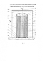
На фиг. 1 изображена схема сварки взрывом, ее продольный осевой разрез, на фиг. 2 - поперечное сечение А-А схемы сварки взрывом, на фиг. 3 - поперечное сечение сваренного композиционного изделия с внутренней полостью, где позиция 22 - сдеформированная трубчатая оболочка из аустенитной стали; 23, 24 - медный и ниобиевый слои сдеформированной трубчатой биметаллической прослойки соответственно; 25 - полостеобразующий элемент в виде титановой трубы, 26 - внутренняя полость изделия, 27, 28 - зоны сварки, полученные при осуществлении способа.In FIG. 1 shows a diagram of explosion welding, its longitudinal axial section, in FIG. 2 is a cross section AA of an explosion welding circuit; FIG. 3 is a cross section of a welded composite product with an internal cavity, where position 22 is a deformed tubular shell made of austenitic steel; 23, 24 - copper and niobium layers of a deformed tubular bimetallic layer, respectively; 25 - cavity-forming element in the form of a titanium pipe, 26 - the internal cavity of the product, 27, 28 - welding zone obtained by the method.
Предлагаемый способ получения композиционных изделий с внутренней полостью сваркой взрывом осуществляется в следующей последовательности. Берут полостеобразующий элемент в виде титановой трубы 1 с толщиной стенки 3-4 мм и размещают внутри его соосно центральный полостеобразующий элемент 2 из стекла с толщиной стенки 10-15 мм и с наружным диаметром, меньшим на 2-4 мм внутреннего диаметра титановой трубы. Предварительно его внутреннюю полость заполняют водным наполнителем 3, а герметизацию с двух его сторон производят заглушками 4, 5, например, из резины. Заполняют промежуток между ними водным наполнителем 6, герметизацию и соосность обеспечивают с помощью металлических втулок 7, 8, покрытых герметиком. Полученную сборку располагают соосно внутри трубчатой оболочки 9 с толщиной стенки 3-4 мм, в зазоре между ними соосно размещают трубчатую биметаллическую прослойку с наружным слоем 10 толщиной 1-1,2 мм из меди, с внутренним слоем 11 толщиной 0,8-1 мм из ниобия, их соосность обеспечивают с помощью металлических втулок 12, 13, 14 и 15. Устанавливают направляющий конус 16, например из стали, с углом при вершине 90°, на наружной поверхности трубчатой оболочки размещают защитную прослойку, например, из резины (на чертеже не показана), защищающую наружную поверхность трубчатой оболочки от повреждений продуктами детонации ВВ, а на ее поверхности располагают контейнер 17 с основным кольцевым зарядом ВВ 18 и расположенным над ним вспомогательным зарядом ВВ 19 с повышенной скоростью детонации. Этот заряд способствует выравниванию фронта детонации в основном заряде ВВ. Размещают данную сборку на песчаном грунте 20 и инициируют процесс детонации в зарядах ВВ с помощью электродетонатора 21.The proposed method for producing composite products with an internal cavity by explosion welding is carried out in the following sequence. A cavity-forming element in the form of a
При осуществлении процесса сварки взрывом используют основной заряд ВВ со скоростью детонации ВВ 3000-3200 м/с, при этом толщину заряда ВВ и сварочные зазоры между свариваемыми металлическими слоями выбирают из условия получения скорости соударения трубчатой оболочки с медным слоем трубчатой биметаллической прослойки в пределах 340-470 м/с и скорости соударения ее ниобиевого слоя с полостеобразующим элементом в виде титановой трубы в пределах 660-700 м/с.When carrying out the explosion welding process, the main explosive charge is used with a detonation velocity of 3000–3200 m / s; the explosive charge thickness and welding gaps between the metal layers being welded are selected from the conditions for obtaining the collision speed of a tubular shell with a copper layer of a tubular bimetallic layer within 340– 470 m / s and the collision velocity of its niobium layer with a cavity-forming element in the form of a titanium pipe in the range of 660-700 m / s.
При взрывном воздействии происходит высокоскоростная радиальная деформация трубчатой оболочки, при ее соударении с медным слоем трубчатой биметаллической прослойки сталь сваривается с медью, затем происходит совместное деформирование образовавшегося трехслойного композита из стали, меди и ниобия и при его соударении с наружной поверхностью полостеобразующего элемента в виде титановой трубы ниобиевый слой сваривается с титановым. Извлекают из внутренней полости сваренной заготовки материал раздробленного центрального полостеобразующего элемента, при этом водный наполнитель удаляется после взрывного нагружения самопроизвольно при разгрузке сжатой системы. После этого удаляют механической обработкой торцевые части полученной заготовки с краевыми эффектами.During explosive action, a high-speed radial deformation of the tubular shell occurs, when it collides with the copper layer of the tubular bimetallic layer, the steel is welded with copper, then the three-layer composite made of steel, copper and niobium is jointly deformed and when it collides with the outer surface of the cavity-forming element in the form of titanium pipe the niobium layer is welded with titanium. The material of the crushed central cavity-forming element is extracted from the inner cavity of the welded billet, while the aqueous filler is removed after explosive loading spontaneously during unloading of the compressed system. After that, the end parts of the obtained workpiece with edge effects are removed by machining.
В результате за один акт взрывного воздействия получают цельносварное композиционное изделие с центральной внутренней полостью цилиндрической формы без нарушений осевой симметрии и герметичности металлических слоев, с полным исключением при этом даже возможности появления в процессе сварки взрывом в зонах сварки металлических слоев хрупких интерметаллидных фаз, которые могли бы снизить долговечность изделия при эксплуатации в условиях частых теплосмен и динамических нагрузок, с обеспечением при этом более низкого, чем у изделий по прототипу, гидравлического сопротивления внутренней полости на единицу длины изделия при пропускании через нее жидкостей-теплоносителей, а также более высокого, чем у изделий по прототипу, термического сопротивления его многослойной стенки при теплообмене веществ, располагаемых в его внутренней полости с окружающей средой. При этом также обеспечивается повышенная стойкость изделия в агрессивных средах, например его наружной поверхности в азотной кислоте, а внутренней, например, в хлоридах.As a result, in one act of explosive action, an all-welded composite product with a central internal cavity of cylindrical shape is obtained without violating axial symmetry and tightness of the metal layers, with the complete exception of even the possibility of the formation of brittle intermetallic phases in the welding zone of the metal layers that could to reduce the durability of the product during operation in conditions of frequent heat exchange and dynamic loads, while ensuring a lower than that of products by the prototype, the hydraulic resistance of the internal cavity per unit length of the product when passing through it fluids, coolants, as well as higher than the products of the prototype, the thermal resistance of its multilayer wall during heat transfer of substances located in its internal cavity with the environment. This also provides increased resistance of the product in aggressive environments, for example, its outer surface in nitric acid, and the inner, for example, in chlorides.
Пример 1 (см. также таблицу).Example 1 (see also table).
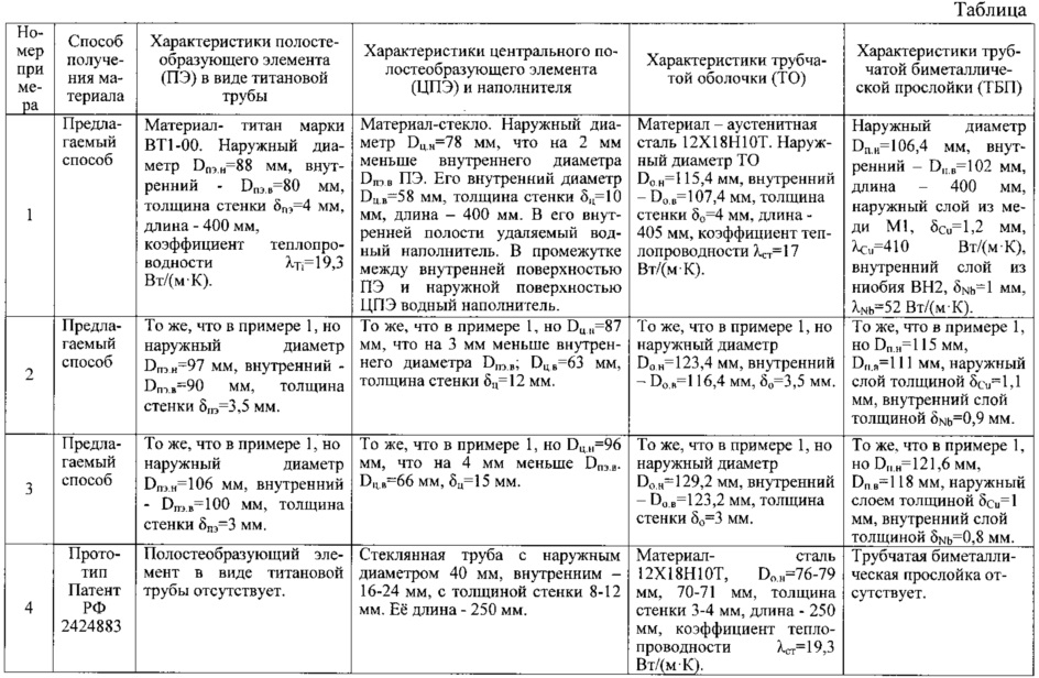
Полостеобразующий элемент (ПЭ) в виде титановой трубы изготавливают из титана ВТ1-00 (ГОСТ 19807-91) с коэффициентом теплопроводности λTi=19,3 Вт/(м⋅К), с наружным диаметром Dпэ.н=88 мм, внутренним Dпэ.в=80 мм, с толщиной стенки δпэ=4 мм, длиной 400 мм.The cavity-forming element (PE) in the form of a titanium pipe is made of VT1-00 titanium (GOST 19807-91) with a thermal conductivity coefficient λ Ti = 19.3 W / (m⋅K), with an external diameter D peq = 88 mm, an internal D pe.v = 80 mm, with a wall thickness of δ pe = 4 mm, 400 mm long.
Центральный полостеобразующий элемент (ЦПЭ), удаляемый после сварки взрывом, изготавливают из стекла (ГОСТ 15130-79) с наружным диаметром Dц.н=78 мм, что на 2 мм меньше внутреннего диаметра Dпэ.в полостеобразующего элемента в виде титановой трубы. Его внутренний диаметр Dц.в=58 мм, толщина стенки δц=10 мм. Заполняют его внутреннюю полость удаляемым после сварки взрывом водным наполнителем, а герметизацию осуществляют с помощью резиновых заглушек. Полученную при этом сборку №1 размещают соосно внутри ПЭ. Заполняют промежуток между внутренней поверхностью ПЭ и наружной поверхностью ЦПЭ водным наполнителем, герметизацию и соосность обеспечивают с помощью металлических втулок, покрытых герметиком. Полученную при этом сборку №2 располагают соосно внутри трубчатой оболочки (ТО), а в зазоре между ними соосно размещают трубчатую биметаллическую прослойку (ТБП), при этом ТО изготавливают из коррозионностойкой аустенитной стали 12Х18Н10Т (ГОСТ 5632-72), обладающей пониженной теплопроводностью. Ее коэффициент теплопроводности λст=17 Вт/(м⋅К). Наружный диаметр ТО Dо.н=115,4 мм, внутренний Dо.в=107,4 мм, толщина стенки δо=4 мм, длина 405 мм.The central cavity-forming element (CPE), which is removed after explosion welding, is made of glass (GOST 15130-79) with an outer diameter D tsn = 78 mm, which is 2 mm less than the inner diameter D pev in the cavity-forming element in the form of a titanium pipe. Its inner diameter D c.v = 58 mm, wall thickness δ c = 10 mm. Fill its internal cavity with a water filler removed by explosion after welding, and the sealing is carried out using rubber plugs. The resulting assembly No. 1 is placed coaxially inside the PE. The gap between the inner surface of the PE and the outer surface of the CPE is filled with a water filler, and sealing and alignment are ensured by metal bushings coated with sealant. The assembly No. 2 obtained in this case is placed coaxially inside the tubular shell (TO), and in the gap between them, a tubular bimetallic interlayer (TBP) is coaxially placed, while the TO is made of corrosion-resistant austenitic steel 12X18H10T (GOST 5632-72), which has reduced thermal conductivity. Its thermal conductivity coefficient λ st = 17 W / (m⋅K). The outer diameter of the TO D o.n = 115.4 mm, the inner D o.v = 107.4 mm, the wall thickness δ o = 4 mm, the length is 405 mm.
ТБП изготавливают, например с помощью сварки взрывом с наружным диаметром Dп.н=106,4 мм, внутренним Dп.в=102 мм, длиной 400 мм, с наружным слоем толщиной δCu=1,2 мм из меди M1 (ГОСТ 859-78), имеющей коэффициент теплопроводности λCu=410 Вт/(м⋅К), с внутренним слоем толщиной δNb=1 мм из ниобия марки ВН2 (ОСТ190023-71) с коэффициентом теплопроводности λNb=52 Вт/(м⋅К).TBP are made, for example, by explosion welding with an outer diameter of D bp = 106.4 mm, an inner D bp = 102 mm, 400 mm long, with an outer layer of thickness δ Cu = 1.2 mm from copper M1 (GOST 859-78), having a thermal conductivity coefficient λ Cu = 410 W / (m⋅K), with an inner layer of thickness δ Nb = 1 mm made of niobium grade ВН2 (ОСТ190023-71) with a thermal conductivity coefficient λ Nb = 52 W / (m⋅ TO).
Соосность ТО, ТБП, а также сборки №2 обеспечивают с помощью металлических втулок, например из алюминия. При выбранных диаметрах ТО, ТБП и ПЭ необходимый сварочный зазор между внутренней поверхностью ТО и наружной поверхностью ТБП h1=0,5 мм, а сварочный зазор между внутренней поверхностью ТБП и наружной поверхностью ПЭ h2=7 мм. Устанавливают направляющий конус из стали Ст3 с углом при вершине 90°, на наружной поверхности трубчатой оболочки размещают защитную прослойку из резины толщиной около 0,8 мм, защищающую наружную поверхность трубчатой оболочки от повреждений продуктами детонации ВВ, а на ее поверхности располагают контейнер из электрокартона с основным кольцевым зарядом ВВ и расположенным над ним вспомогательным зарядом ВВ с повышенной скоростью детонации (аммонит 6ЖВ). Этот заряд способствует выравниванию фронта детонации в основном заряде ВВ. Размещают данную сборку на песчаном грунте и инициируют процесс детонации в зарядах ВВ с помощью электродетонатора.The alignment of TO, TBP, and assembly No. 2 is ensured by metal bushings, for example, from aluminum. With the selected diameters of TO, TBP and PE, the required welding gap between the inner surface of the TO and the outer surface of the TBP is h 1 = 0.5 mm, and the welding gap between the inner surface of the TBP and the outer surface of PE is h 2 = 7 mm. A guide cone is made of St3 steel with an angle at the apex of 90 °, a protective layer of rubber about 0.8 mm thick is placed on the outer surface of the tubular shell, protecting the outer surface of the tubular shell from damage by explosive detonation products, and a container of electric cardboard with the main ring explosive charge and an auxiliary explosive charge located above it with an increased detonation velocity (6GV ammonite). This charge helps to equalize the detonation front in the main explosive charge. Place this assembly on sandy soil and initiate the detonation process in explosive charges using an electric detonator.
При осуществлении процесса сварки взрывом используют основной заряд ВВ в виде смеси аммонита 6ЖВ с аммиачной селитрой в соотношении 1:2,33. Его наружный диаметр dн=417 мм, внутренний dв=117 мм, толщина в районе расположения трубчатой оболочки Твв=150 мм, плотность Пвв=0,94 г/см3, скорость детонации Двв=3000 м/с, общая длина 510 мм вместе с вспомогательным зарядом ВВ, имеющим толщину 20 мм. При выбранных параметрах схемы сварки взрывом скорость соударения ТО с медным слоем ТБП в пределах V1=340 м/с, а скорость соударения ее ниобиевого слоя с ПЭ в виде титановой трубы V2=660 м/с. Скорости соударения V1 и V2 определяются расчетным путем с помощью компьютерной технологии.When carrying out the explosion welding process, the main explosive charge is used in the form of a mixture of 6GV ammonite with ammonium nitrate in a ratio of 1: 2.33. Its outer diameter d n = 417 mm, inner d in = 117 mm, the thickness in the region of the location of the tubular shell T BB = 150 mm, the density P BB = 0.94 g / cm 3 , the detonation velocity D BB = 3000 m / s, the total length of 510 mm together with an auxiliary explosive charge having a thickness of 20 mm With the selected parameters of the explosion welding scheme, the speed of impact of TO with the TBP copper layer is within V 1 = 340 m / s, and the speed of impact of its niobium layer with PE in the form of a titanium pipe is V 2 = 660 m / s. Collision speeds V 1 and V 2 are determined by calculation using computer technology.
Извлекают из внутренней полости сваренной заготовки материал раздробленного центрального полостеобразующего элемента. Водный наполнитель удаляется из полостей после взрывного нагружения самопроизвольно при разгрузке сжатой системы. После этого удаляют механической обработкой торцевые части полученной заготовки с краевыми эффектами - по 20 мм с каждой стороны.The material of the crushed central cavity-forming element is removed from the inner cavity of the welded billet. Water filler is removed from the cavities after explosive loading spontaneously during unloading of the compressed system. After that, the end parts of the obtained workpiece with edge effects are removed by machining - 20 mm on each side.
В результате за один акт взрывного воздействия получают цельносварное композиционное изделие с центральной внутренней полостью цилиндрической формы без нарушений осевой симметрии и герметичности металлических слоев, без появления в процессе сварки взрывом в зонах сварки металлических слоев хрупких интерметаллидных фаз, которые могли бы снизить долговечность изделия при эксплуатации в условиях частых теплосмен и динамических нагрузок. Его наружный диаметр 102,2 мм, внутренний 80 мм, толщина наружного стального слоя δ1=4,6 мм, смежного с ним медного δ2=1,4 мм, смежного с ним ниобиевого δ3=1,1 мм, внутреннего титанового δ4=4 мм, длина изделия 360 мм. Гидравлическое сопротивление его внутренней полости, приходящееся на единицу длины изделия при пропускании через нее жидкостей-теплоносителей, оцениваемое по величине потери давления (напора), в 3,9-5,2 раза меньше, чем у изделий по прототипу, а термическое сопротивление его четырехслойной стенки (Rсум) при направлении теплопередачи поперек слоев, определяемое как сумма термических сопротивлений каждого из слоев (отношение толщины слоя к коэффициенту его теплопроводности), равно: Rсум=502⋅10-6 К/(Вт/м2), что в 1,8-2,5 раза больше, чем у изделий, полученных по прототипу, при этом также обеспечивается повышенная стойкость изделия в агрессивных средах, например его наружной поверхности - в азотной кислоте, а внутренней, например, в хлоридах.As a result, in one act of explosive action, an all-welded composite product with a central internal cavity of cylindrical shape is obtained without breaking axial symmetry and tightness of metal layers, without the appearance of brittle intermetallic phases during explosion welding in the welding zones of metal layers, which could reduce the product durability during operation in conditions of frequent heat exchange and dynamic loads. Its outer diameter is 102.2 mm, the inner is 80 mm, the thickness of the outer steel layer is δ 1 = 4.6 mm, the adjacent copper δ 2 = 1.4 mm, the adjacent niobium δ 3 = 1.1 mm, and the inner titanium δ 4 = 4 mm, product length 360 mm. The hydraulic resistance of its internal cavity per unit length of the product when passing through it coolant fluids, estimated by the value of pressure loss (pressure), is 3.9-5.2 times less than that of the products of the prototype, and its thermal resistance is four-layer walls (R sum ) with the heat transfer direction across the layers, defined as the sum of the thermal resistances of each layer (the ratio of the layer thickness to its thermal conductivity), is equal to: R sum = 502 =10 -6 K / (W / m 2 ), which 1.8-2.5 times more than products, p radiation according to the prototype, while also products provided improved resistance to corrosive environments, such as its outer surface - in nitric acid, and the inside, for example, a chloride.
Пример 2 (см. также таблицу).Example 2 (see also table).
То же, что в примере 1, но внесены следующие изменения.The same as in example 1, but the following changes.
ПЭ в виде титановой трубы изготавливают с наружным диаметром Dпэ.н=97 мм, внутренним Dпэ.в=90 мм, с толщиной стенки δпэ=3,5 мм.PE in the form of a titanium pipe is made with an external diameter D pe = 97 mm, an internal D pe = 90 mm, and a wall thickness δ pe = 3.5 mm.
ЦПЭ, удаляемый после сварки взрывом, изготавливают с наружным диаметром Dц.н=87 мм, что на 3 мм меньше внутреннего диаметра Dпэ.в полостеобразующего элемента в виде титановой трубы. Его внутренний диаметр Dц.в=63 мм, толщина стенки δц=12 мм.The CPE removed after explosion welding is made with an outer diameter D tsn = 87 mm, which is 3 mm less than the inner diameter D pe in a cavity- forming element in the form of a titanium pipe. Its internal diameter D c.v = 63 mm, wall thickness δ c = 12 mm.
ТО изготавливают с наружным диаметром Dо.н=123,4 мм, внутренним Dо.в=116,4 мм, толщина стенки δо=3,5 мм.THAT is made with an outer diameter D о.н = 123.4 mm, an internal D о.в = 116.4 mm, wall thickness δ о = 3.5 mm.
ТБП изготавливают с наружным диаметром Dп.н=115 мм, внутренним Dп.в=111 мм, с наружным слоем толщиной δCu=1,1 мм, с внутренним слоем толщиной δNb=0,9 мм.TBP are made with an outer diameter of D bp = 115 mm, an inner D of bp = 111 mm, with an outer layer of thickness δ Cu = 1.1 mm, with an inner layer of thickness δ Nb = 0.9 mm.
При выбранных диаметрах ТО, ТБП и ПЭ необходимый сварочный зазор между внутренней поверхностью ТО и наружной поверхностью ТБП h1=0,7 мм, а сварочный зазор между внутренней поверхностью ТБП и наружной поверхностью ПЭ h2=7 мм. При осуществлении процесса сварки взрывом используют основной заряд ВВ, в виде смеси аммонита 6ЖВ с аммиачной селитрой в соотношении 1:2. Его наружный диаметр dн=412 мм, внутренний (с учетом защитной прослойки из резины толщиной около 1 мм) - dв=112 мм, Твв=150 мм, плотность Пвв=0,93 г/см3, скорость детонации Двв=3100 м/с.With the selected diameters of TO, TBP and PE, the required welding gap between the inner surface of the TO and the outer surface of the TBP is h 1 = 0.7 mm, and the welding gap between the inner surface of the TBP and the outer surface of PE is h 2 = 7 mm. When carrying out the explosion welding process, the main explosive charge is used, in the form of a mixture of 6GV ammonite with ammonium nitrate in a ratio of 1: 2. Its outer diameter d n = 412 mm, internal (taking into account the protective layer of rubber with a thickness of about 1 mm) - d in = 112 mm, T BB = 150 mm, density P BB = 0.93 g / cm 3 , detonation speed D cc = 3100 m / s.
При выбранных параметрах схемы сварки взрывом скорость соударения ТО с медным слоем ТБП в пределах V1=420 м/с, а скорость соударения ее ниобиевого слоя с ПЭ в виде титановой трубы V2=680 м/с.With the selected parameters of the explosion welding scheme, the collision speed of the TO with the TBP copper layer is within V 1 = 420 m / s, and the collision velocity of its niobium layer with PE in the form of a titanium pipe is V 2 = 680 m / s.
Результаты те же, что и в примере 1, но получают цельносварное композиционное изделие с наружным диаметром 109,5 мм, внутренним - 90 мм, толщина наружного стального слоя δ1=4 мм, смежного с ним медного δ2=1,25 мм,- смежного с ним ниобиевого δ3=1 мм, внутреннего титанового δ4=3,5 мм. Гидравлическое сопротивление его внутренней полости, приходящееся на единицу длины изделия при пропускании через нее жидкостей-теплоносителей в 6,2-8,3 раза меньше чем у изделий по прототипу, а термическое сопротивление Rсум=439⋅10-6 К/(Вт/м2), что в 1,6-2,2 раза больше, чем у изделий, полученных по прототипу.The results are the same as in example 1, but they receive an all-welded composite product with an outer diameter of 109.5 mm, an inner diameter of 90 mm, the thickness of the outer steel layer δ 1 = 4 mm, the adjacent copper layer δ 2 = 1.25 mm, - adjacent niobium δ 3 = 1 mm, internal titanium δ 4 = 3.5 mm Hydraulic resistance of its internal cavities per unit length of the article by passing it through heat transfer fluid in 6,2-8,3 times smaller than that of prior art products, and the thermal resistance R sum = 439⋅10 -6 K / (W / m 2 ), which is 1.6-2.2 times more than that of products obtained by the prototype.
Пример 3 (см. также таблицу).Example 3 (see also table).
То же, что в примере 1, но внесены следующие изменения.The same as in example 1, but the following changes.
ПЭ в виде титановой трубы изготавливают с наружным диаметром Dпэ.н=106 мм, внутренним Dпэ.в=100 мм, с толщиной стенки δпэ=3 мм.PE in the form of a titanium pipe is made with an outer diameter of D pe = 106 mm, an inner D pe.v = 100 mm, and a wall thickness of δ pe = 3 mm.
ЦПЭ изготавливают с наружным диаметром Dц.н=96 мм, что на 4 мм меньше внутреннего диаметра Dпэ.в полостеобразующего элемента в виде титановой трубы. Его внутренний диаметр Dц.в=66 мм, толщина стенки δц=15 мм.CPEs are made with an outer diameter D tsn = 96 mm, which is 4 mm less than the inner diameter D pe in a cavity- forming element in the form of a titanium pipe. Its internal diameter D c.v = 66 mm, wall thickness δ c = 15 mm.
ТО изготавливают с наружным диаметром Dо.н=129,2 мм, внутренним Dо.в=123,2 мм, толщина стенки δо=3 мм.THAT is made with an outer diameter D о.н = 129.2 mm, an internal D о.в = 123.2 mm, wall thickness δ о = 3 mm.
ТБП изготавливают с наружным диаметром Dп.н=121,6 мм, внутренним Dп.в=118 мм, с наружным слоем толщиной δCu=1 мм, с внутренним слоем толщиной δNb=0,8 мм.TBP are made with an outer diameter of D bp = 121.6 mm, an inner D pb = 118 mm, with an outer layer of thickness δ Cu = 1 mm, with an inner layer of thickness δ Nb = 0.8 mm.
При выбранных диаметрах ТО, ТБП и ПЭ необходимый сварочный зазор между внутренней поверхностью ТО и наружной поверхностью ТБП h1=0,8 мм, а сварочный зазор между внутренней поверхностью ТБП и наружной поверхностью ПЭ h2=6 мм. При осуществлении процесса сварки взрывом используют основной заряд ВВ, в виде смеси аммонита 6ЖВ с аммиачной селитрой в соотношении 1:1,86. Его наружный диаметр dн=419 мм, внутренний dв=119 мм, толщина Твв=150 мм, плотность Пвв=0,93 г/см3, скорость детонации Двв=3200 м/с.With the selected diameters of TO, TBP and PE, the required welding gap between the inner surface of the TO and the outer surface of the TBP is h 1 = 0.8 mm, and the welding gap between the inner surface of the TBP and the outer surface of PE is h 2 = 6 mm. When carrying out the explosion welding process, the main explosive charge is used, in the form of a mixture of 6GV ammonite with ammonium nitrate in a ratio of 1: 1.86. Its outer diameter d n = 419 mm, internal d in = 119 mm, the thickness T BB = 150 mm, the density P BB = 0.93 g / cm 3 , the detonation velocity D BB = 3200 m / s.
При выбранных параметрах схемы сварки взрывом скорость соударения ТО с медным слоем ТБП в пределах V1=470 м/с, а скорость соударения ее ниобиевого слоя с ПЭ в виде титановой трубы V2=700 м/с.With the selected parameters of the explosion welding scheme, the speed of impact of the TO with the TBP copper layer is within V 1 = 470 m / s, and the speed of impact of its niobium layer with PE in the form of a titanium pipe is V 2 = 700 m / s.
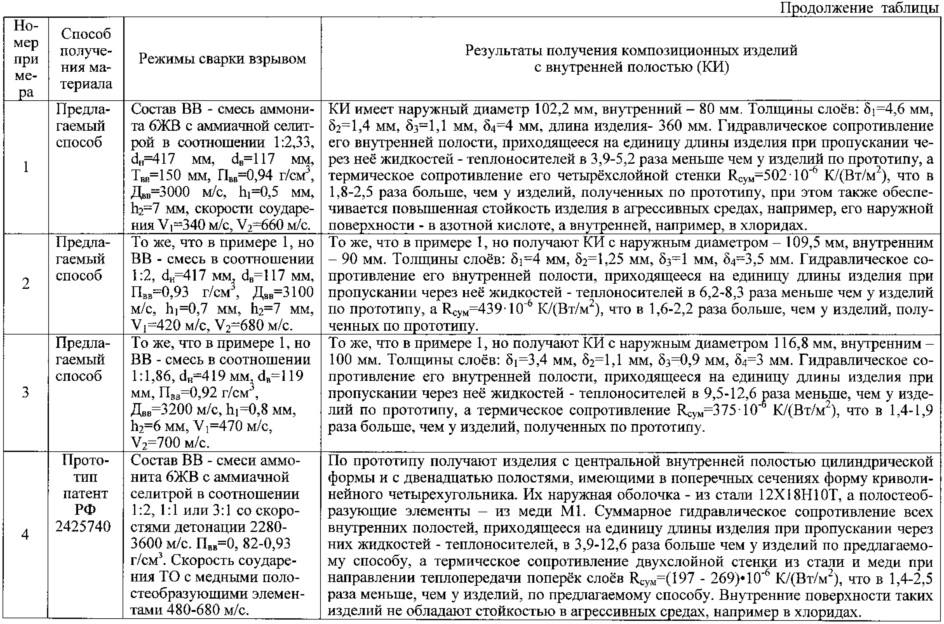
Результаты те же, что и в примере 1, но получают цельносварное композиционное изделие с наружным диаметром 116,8 мм, внутренним 100 мм, толщина наружного стального слоя δ1=3,4 мм, смежного с ним медного δ2=1,1 мм, смежного с ним ниобиевого δ3=0,9 мм, внутреннего титанового δ4=3 мм. Гидравлическое сопротивление его внутренней полости, приходящееся на единицу длины изделия при пропускании через нее жидкостей-теплоносителей в 9,5-12,6 раза меньше, чем у изделий по прототипу, а термическое сопротивление Rсум=375⋅10-6 К/(Вт/м2), что в 1,4-1,9 раза больше, чем у изделий, полученных по прототипу.The results are the same as in example 1, but get an all-welded composite product with an outer diameter of 116.8 mm, an inner 100 mm, the thickness of the outer steel layer δ 1 = 3.4 mm, adjacent copper δ 2 = 1.1 mm adjacent to it niobium δ 3 = 0.9 mm, internal titanium δ 4 = 3 mm The hydraulic resistance of its internal cavity per unit length of the product when passing through it heat-transfer fluids is 9.5-12.6 times less than that of the products of the prototype, and the thermal resistance R sum = 375⋅10 -6 K / (W / m 2 ), which is 1.4-1.9 times more than that of products obtained by the prototype.
В изделиях, изготовленных по прототипу (см. таблицу, пример 4), получают цельносварные изделия с центральной внутренней полостью цилиндрической формы и с двенадцатью полостями, имеющими в поперечных сечениях форму криволинейного четырехугольника. Их наружная оболочка выполнена из стали 12Х18Н10Т, а полостеобразующие элементы - из меди M1. В каждом таком изделии суммарное гидравлическое сопротивление всех внутренних полостей, приходящееся на единицу длины изделия при одновременном пропускании через них жидкостей-теплоносителей, в 3,9-12,6 раза больше, чем у изделий по предлагаемому способу, а термическое сопротивление двухслойной стенки из стали и меди при направлении теплопередачи поперек слоев Rсум=(197-269)⋅10-6 К/(Вт/м2), что в 1,4-2,5 раза меньше, чем у изделий, полученных по предлагаемому способу. Кроме того, внутренние поверхности изделий по прототипу не обладают стойкостью в агрессивных средах, например в хлоридах.In products made according to the prototype (see table, example 4), all-welded products with a central inner cavity of a cylindrical shape and with twelve cavities having a curved quadrangle in cross sections are obtained. Their outer shell is made of steel 12X18H10T, and the cavity-forming elements are made of M1 copper. In each such product, the total hydraulic resistance of all internal cavities per unit length of the product while passing heat-transfer fluids through them is 3.9-12.6 times greater than that of products by the proposed method, and the thermal resistance of the two-layer wall is made of steel and copper when the direction of heat transfer across the layers R sum = (197-269) ⋅ 10 -6 K / (W / m 2 ), which is 1.4-2.5 times less than that of products obtained by the proposed method. In addition, the inner surfaces of the products of the prototype do not have resistance in aggressive environments, such as chlorides.
Claims (1)
Priority Applications (1)
| Application Number | Priority Date | Filing Date | Title |
|---|---|---|---|
| RU2016124568A RU2632503C1 (en) | 2016-06-20 | 2016-06-20 | Method of producing composite products with inner cavity by means of explosion welding |
Applications Claiming Priority (1)
| Application Number | Priority Date | Filing Date | Title |
|---|---|---|---|
| RU2016124568A RU2632503C1 (en) | 2016-06-20 | 2016-06-20 | Method of producing composite products with inner cavity by means of explosion welding |
Publications (1)
| Publication Number | Publication Date |
|---|---|
| RU2632503C1 true RU2632503C1 (en) | 2017-10-05 |
Family
ID=60040723
Family Applications (1)
| Application Number | Title | Priority Date | Filing Date |
|---|---|---|---|
| RU2016124568A RU2632503C1 (en) | 2016-06-20 | 2016-06-20 | Method of producing composite products with inner cavity by means of explosion welding |
Country Status (1)
| Country | Link |
|---|---|
| RU (1) | RU2632503C1 (en) |
Cited By (2)
| Publication number | Priority date | Publication date | Assignee | Title |
|---|---|---|---|---|
| CN115945773A (en) * | 2023-02-13 | 2023-04-11 | 中国人民解放军陆军工程大学 | A preparation method of large-scale multilayer titanium-aluminum composite pipe based on explosive welding |
| CN118008935A (en) * | 2024-03-07 | 2024-05-10 | 海安县恒益滑动轴承有限公司 | Composite press-down nut for metallurgical rolling mill based on explosive composite process and preparation method thereof |
Citations (5)
| Publication number | Priority date | Publication date | Assignee | Title |
|---|---|---|---|---|
| US3761004A (en) * | 1972-04-10 | 1973-09-25 | E F Industries | Assembly for explosively bonding together metal layers and tubes |
| SU1732572A1 (en) * | 1989-11-10 | 1997-06-20 | Волгоградский Политехнический Институт | Method of manufacture of superconducting articles with inner space by explosion welding |
| RU2404035C1 (en) * | 2009-03-05 | 2010-11-20 | Институт гидродинамики им. М.А. Лаврентьева Сибирского отделения Российской академии наук (ИГиЛ СО РАН) | Method of producing composite materials using explosives power |
| RU2424883C1 (en) * | 2010-05-07 | 2011-07-27 | Государственное образовательное учреждение высшего профессионального образования Волгоградский государственный технический университет (ВолгГТУ) | Method of producing composite articles with inner cavities by explosion welding |
| RU2425739C1 (en) * | 2010-05-07 | 2011-08-10 | Государственное образовательное учреждение высшего профессионального образования Волгоградский государственный технический университет (ВолгГТУ) | Explosion welding procedure for production of cylinder composite items with internal cavities |
-
2016
- 2016-06-20 RU RU2016124568A patent/RU2632503C1/en not_active IP Right Cessation
Patent Citations (5)
| Publication number | Priority date | Publication date | Assignee | Title |
|---|---|---|---|---|
| US3761004A (en) * | 1972-04-10 | 1973-09-25 | E F Industries | Assembly for explosively bonding together metal layers and tubes |
| SU1732572A1 (en) * | 1989-11-10 | 1997-06-20 | Волгоградский Политехнический Институт | Method of manufacture of superconducting articles with inner space by explosion welding |
| RU2404035C1 (en) * | 2009-03-05 | 2010-11-20 | Институт гидродинамики им. М.А. Лаврентьева Сибирского отделения Российской академии наук (ИГиЛ СО РАН) | Method of producing composite materials using explosives power |
| RU2424883C1 (en) * | 2010-05-07 | 2011-07-27 | Государственное образовательное учреждение высшего профессионального образования Волгоградский государственный технический университет (ВолгГТУ) | Method of producing composite articles with inner cavities by explosion welding |
| RU2425739C1 (en) * | 2010-05-07 | 2011-08-10 | Государственное образовательное учреждение высшего профессионального образования Волгоградский государственный технический университет (ВолгГТУ) | Explosion welding procedure for production of cylinder composite items with internal cavities |
Cited By (2)
| Publication number | Priority date | Publication date | Assignee | Title |
|---|---|---|---|---|
| CN115945773A (en) * | 2023-02-13 | 2023-04-11 | 中国人民解放军陆军工程大学 | A preparation method of large-scale multilayer titanium-aluminum composite pipe based on explosive welding |
| CN118008935A (en) * | 2024-03-07 | 2024-05-10 | 海安县恒益滑动轴承有限公司 | Composite press-down nut for metallurgical rolling mill based on explosive composite process and preparation method thereof |
Similar Documents
| Publication | Publication Date | Title |
|---|---|---|
| RU2425739C1 (en) | Explosion welding procedure for production of cylinder composite items with internal cavities | |
| US3140537A (en) | Explosive welding process | |
| Findik | Recent developments in explosive welding | |
| RU2632503C1 (en) | Method of producing composite products with inner cavity by means of explosion welding | |
| Bataev | Structure of explosively welded materials: experimental study and numerical simulation | |
| Giri et al. | A study on the effect of weld groove designs on residual stresses in SS 304LN thick multipass pipe welds | |
| RU2373035C1 (en) | Method of fabricating items with internal cavities by means of explosive loading | |
| RU2424883C1 (en) | Method of producing composite articles with inner cavities by explosion welding | |
| Agu | The effects of 3D printed material properties on shaped charge liner performance | |
| US20210268563A1 (en) | Systems and methods for production of metallurgically bonded clad billet and products thereof, and metallurgically bonded clad billet | |
| RU2618263C1 (en) | Production method of the composite products with the inner cavity by explosion welding | |
| RU2632501C1 (en) | Method of producing composite products with inner cavity by means of explosion welding | |
| RU2618262C1 (en) | Production of composite articles with internal cavities by blast welding | |
| US4455733A (en) | Furnace cooling elements and method of forming furnace cooling elements | |
| RU2355536C1 (en) | Method of obtaining objects with inner cavities through explosive welding | |
| Balaji et al. | Comparative analysis of experimental and numerical investigation on multiple projectile impact of AA5083 friction stir welded targets | |
| US4518111A (en) | Method of fabricating a bi-metal tube | |
| RU2425740C1 (en) | Explosion welding procedure for production of items with internal cavities | |
| RU2613511C1 (en) | Method for producing composite articles with inner cavity by means of explosion welding | |
| RU2353487C1 (en) | Method of producing objects with inner cavities by explosion welding | |
| RU2632502C1 (en) | Method of producing composite products with inner cavity by means of explosion welding | |
| Zhou et al. | Microstructure Analysis and Mechanical Performance of TA10/6061 Large Size Explosive Welding Composite Pipes Based on Numerical Simulation Verification | |
| CN116423028B (en) | Dynamic self-restraint explosive welding method for preparing bimetal composite pipe | |
| Wąsek et al. | The analysis of Al-Cu bimetallic bars bond layers joined by the explosive method | |
| RU2526355C1 (en) | Method of production of composite products with internal cavities by explosion welding |
Legal Events
| Date | Code | Title | Description |
|---|---|---|---|
| MM4A | The patent is invalid due to non-payment of fees |
Effective date: 20180621 |