RU2627226C2 - Motor vehicle with central console containing air conditioning system - Google Patents
Motor vehicle with central console containing air conditioning system Download PDFInfo
- Publication number
- RU2627226C2 RU2627226C2 RU2014153118A RU2014153118A RU2627226C2 RU 2627226 C2 RU2627226 C2 RU 2627226C2 RU 2014153118 A RU2014153118 A RU 2014153118A RU 2014153118 A RU2014153118 A RU 2014153118A RU 2627226 C2 RU2627226 C2 RU 2627226C2
- Authority
- RU
- Russia
- Prior art keywords
- seats
- air
- air conditioning
- motor vehicle
- row
- Prior art date
Links
Images
Classifications
-
- B—PERFORMING OPERATIONS; TRANSPORTING
- B60—VEHICLES IN GENERAL
- B60H—ARRANGEMENTS OF HEATING, COOLING, VENTILATING OR OTHER AIR-TREATING DEVICES SPECIALLY ADAPTED FOR PASSENGER OR GOODS SPACES OF VEHICLES
- B60H1/00—Heating, cooling or ventilating [HVAC] devices
- B60H1/00007—Combined heating, ventilating, or cooling devices
- B60H1/00207—Combined heating, ventilating, or cooling devices characterised by the position of the HVAC devices with respect to the passenger compartment
-
- B—PERFORMING OPERATIONS; TRANSPORTING
- B60—VEHICLES IN GENERAL
- B60H—ARRANGEMENTS OF HEATING, COOLING, VENTILATING OR OTHER AIR-TREATING DEVICES SPECIALLY ADAPTED FOR PASSENGER OR GOODS SPACES OF VEHICLES
- B60H1/00—Heating, cooling or ventilating [HVAC] devices
-
- B—PERFORMING OPERATIONS; TRANSPORTING
- B60—VEHICLES IN GENERAL
- B60H—ARRANGEMENTS OF HEATING, COOLING, VENTILATING OR OTHER AIR-TREATING DEVICES SPECIALLY ADAPTED FOR PASSENGER OR GOODS SPACES OF VEHICLES
- B60H1/00—Heating, cooling or ventilating [HVAC] devices
- B60H1/00007—Combined heating, ventilating, or cooling devices
- B60H1/00021—Air flow details of HVAC devices
- B60H2001/00078—Assembling, manufacturing or layout details
- B60H2001/00099—Assembling, manufacturing or layout details comprising additional ventilating means
-
- B—PERFORMING OPERATIONS; TRANSPORTING
- B60—VEHICLES IN GENERAL
- B60H—ARRANGEMENTS OF HEATING, COOLING, VENTILATING OR OTHER AIR-TREATING DEVICES SPECIALLY ADAPTED FOR PASSENGER OR GOODS SPACES OF VEHICLES
- B60H1/00—Heating, cooling or ventilating [HVAC] devices
- B60H1/00007—Combined heating, ventilating, or cooling devices
- B60H1/00207—Combined heating, ventilating, or cooling devices characterised by the position of the HVAC devices with respect to the passenger compartment
- B60H2001/00228—Devices in the interior of the passenger compartment
Abstract
Description
Изобретение относится к автотранспортным средствам, в частности к системам кондиционирования воздуха в автотранспортных средствах.The invention relates to vehicles, in particular to air conditioning systems in vehicles.
В частности, изобретение относится к системам кондиционирования воздуха, размещаемым в центральной консоли между передними сидениями автотранспортного средства.In particular, the invention relates to air conditioning systems placed in a center console between the front seats of a vehicle.
Обычно системы кондиционирования воздуха монтируются в приборной панели автотранспортного средства и предназначены для направления холодного или теплого воздуха в кабину автотранспортного средства через множество вентиляционных отверстий, расположенных в приборной панели.Typically, air conditioning systems are mounted in the dashboard of a vehicle and are designed to direct cold or warm air into the cabin of the vehicle through a variety of ventilation holes located in the dashboard.
Однако подобные системы кондиционирования воздуха не способны направить достаточно воздуха в заднюю часть автотранспортного средства, в частности к задним сидениям. Для направления воздуха к задним сидениям между системой кондиционирования воздуха должен быть установлен воздухопровод.However, such air conditioning systems are not able to direct enough air to the rear of the vehicle, in particular to the rear seats. An air line must be installed between the air conditioning system to direct air to the rear seats.
В подобных системах кондиционирования воздуха размеры и мощность вентиляционной системы должны быть большими из-за потерь давления в воздухопроводе, что приводит к чрезмерной громоздкости системы кондиционирования воздуха и, естественно, к увеличению стоимости.In such air conditioning systems, the size and power of the ventilation system must be large due to pressure losses in the air duct, which leads to excessive cumbersome air conditioning systems and, of course, to increase the cost.
Кроме того, подобная подача воздуха не может управляться раздельно пассажирами, сидящими сзади.In addition, such air supply cannot be controlled separately by passengers sitting in the back.
В документе US 20080245501 описан кондиционер центральной консоли для автотранспортного средства, установленный между передними сидениями и содержащий вентиляционную систему, испаритель и отопительный радиатор, расположенные горизонтально один за другим. Кондиционер имеет вентиляционные отверстия, соединенные с боковыми стойками автотранспортного средства с помощью шлангов, встроенных в стойки, для улучшения эффективности устранения запотевания стекол на уровне задних сидений.US20080245501 describes a center console air conditioner for a vehicle mounted between front seats and comprising a ventilation system, an evaporator and a heating radiator arranged horizontally one after the other. The air conditioner has ventilation openings connected to the side racks of the vehicle using hoses built into the racks to improve the efficiency of eliminating fogging of the windows at the level of the rear seats.
Однако подобная система кондиционирования воздуха, полученные размеры и мощность вентиляционной системы все еще остаются очень большими из-за потерь давления в воздухопроводах.However, such an air conditioning system, the obtained dimensions and power of the ventilation system still remain very large due to pressure losses in the air ducts.
Кроме того, из-за этих требований габаритные размеры такого кондиционера увеличились, равно как и количество деталей, необходимых для достижения охлаждения, достаточного для пассажиров, сидящих сзади. Соответственно, стоимость такого кондиционера будет очень большая.In addition, due to these requirements, the overall dimensions of such an air conditioner have increased, as well as the number of parts necessary to achieve cooling, sufficient for passengers sitting in the back. Accordingly, the cost of such an air conditioner will be very large.
Задача изобретения состоит в устранении вышеуказанных недостатков, присущих известным системам кондиционирования.The objective of the invention is to eliminate the above disadvantages inherent in known air conditioning systems.
Задача изобретения состоит в создании системы кондиционирования воздуха, выполненной с возможностью направлять достаточное количество воздуха к задним сидениям и имеющей раздельное управление для пассажиров, сидящих сзади.The objective of the invention is to create an air conditioning system, configured to direct a sufficient amount of air to the rear seats and having separate control for passengers sitting in the back.
Также задача изобретения состоит в создании системы кондиционирования воздуха, имеющей очень компактные размеры для того, чтобы предоставить пассажирам, сидящим в центре сзади, достаточно места для ног.It is also an object of the invention to provide an air conditioning system having a very compact size in order to provide passengers sitting in the center rear with enough legroom.
Еще одна задача изобретения состоит в снижении стоимости системы кондиционирования воздуха за счет уменьшения количества деталей, используемых в системе кондиционирования воздуха.Another objective of the invention is to reduce the cost of the air conditioning system by reducing the number of parts used in the air conditioning system.
Поставленная задача решена в автотранспортном средстве, имеющем по меньшей мере два ряда сидений и центральную консоль, расположенную между двумя сидениями первого ряда сидений вначале второго ряда сидений. Указанная центральная консоль имеет систему кондиционирования воздуха, выполненную с возможностью нагнетать воздух ко второму ряду сидений.The problem is solved in a motor vehicle having at least two rows of seats and a center console located between two seats of the first row of seats at the beginning of the second row of seats. Said center console has an air conditioning system configured to pump air to the second row of seats.
Система кондиционирования воздуха имеет кожух, вентиляционную систему или вентилятор и теплообменник, при этом вентиляционная система и теплообменник установлены внутри кожуха и расположены вертикально один над другим.The air conditioning system has a casing, a ventilation system or a fan and a heat exchanger, while the ventilation system and the heat exchanger are installed inside the casing and are arranged vertically one above the other.
Такая система кондиционирования воздуха имеет очень компактные размеры для того, чтобы оставить достаточно места для ног пассажиров, сидящих посредине сзади.Such an air conditioning system has a very compact size in order to leave enough room for the legs of passengers sitting in the middle of the back.
Кожух имеет преимущественно спиралеобразный отсек для вентиляционной системы, воздухопровод приема воздуха, через который нагнетаемый вентиляционной системой воздух направляется к теплообменнику, и единственное вентиляционное отверстие, соединенное с выпускным воздуховодом, направляющим воздух ко второму ряду сидений.The casing has a predominantly spiral-shaped compartment for the ventilation system, an air intake duct through which air blown by the ventilation system is directed to the heat exchanger, and a single ventilation opening connected to an exhaust duct directing air to the second row of seats.
Например, вентиляционное отверстие имеет разнонаправленные устройства для нагнетания воздуха.For example, a vent has multidirectional devices for pumping air.
Кожух может состоять из двух симметричных частей кожуха.The casing may consist of two symmetrical parts of the casing.
Теплообменником, например, является испаритель.A heat exchanger, for example, is an evaporator.
В соответствии с вариантом осуществления, вентиляционная система содержит, по меньшей мере, рабочее колесо или вентилятор, установленный на вал электромотора.According to an embodiment, the ventilation system comprises at least an impeller or fan mounted on an electric motor shaft.
Центральная консоль имеет преимущественно устройство управления, чтобы управлять системой кондиционирования воздуха.The center console has a predominantly control device to control the air conditioning system.
Ширина центральной консоли меньше или равна ширине спинки первого ряда сидений.The width of the center console is less than or equal to the width of the back of the first row of seats.
В соответствии с вариантом осуществления автотранспортное средство имеет три ряда сидений.According to an embodiment, the vehicle has three rows of seats.
Изобретение будет лучше понято при более детальном рассмотрении нескольких вариантов его осуществления, приведенных в качестве неограничивающего примера со ссылкой на прилагаемые чертежи.The invention will be better understood by a more detailed consideration of several options for its implementation, given as a non-limiting example with reference to the accompanying drawings.
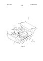
На фиг. 1 схематично показана часть автотранспортного средства в соответствии с изобретением, вид в перспективе;In FIG. 1 schematically shows a part of a motor vehicle in accordance with the invention, a perspective view;
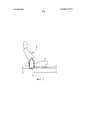
на фиг. 2 показана часть автотранспортного средства, показанного на фиг. 1, вид сбоку;in FIG. 2 shows a portion of the vehicle shown in FIG. 1, side view;
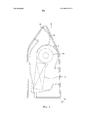
на фиг. 3 детально показана центральная консоль в соответствии с фиг. 2;in FIG. 3 shows in detail the center console in accordance with FIG. 2;
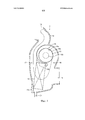
на фиг. 4 показана система кондиционирования воздуха в соответствии с фиг. 3, вид в осевом разрезе.in FIG. 4 shows an air conditioning system in accordance with FIG. 3 is an axial sectional view.
В ходе описания, термины «продольный», «поперечный», «вертикальный», «передний», «задний»», левый», «правый» определены в соответствии с обычной ортогональной системой координат автотранспортного средства с двигателем, иллюстрированной на фиг. 1 и содержащей:Throughout the description, the terms “longitudinal”, “transverse”, “vertical”, “front”, “rear”, “left”, “right” are defined in accordance with the conventional orthogonal coordinate system of a motor vehicle with an engine, illustrated in FIG. 1 and containing:
- продольную ось X, расположенную горизонтально и направленную от передней к задней части автотранспортного средства;- the longitudinal axis X, located horizontally and directed from the front to the rear of the vehicle;
- поперечную ось Y, расположенную горизонтально перпендикулярно продольной оси X и направленную слева направо автотранспортного средства, перемещаясь к передней части;- the transverse axis Y, located horizontally perpendicular to the longitudinal axis X and directed from left to right of the vehicle, moving to the front;
- вертикальную ось Z, расположенную ортогонально к продольной и поперечной осям Χ, Y.- the vertical axis Z located orthogonally to the longitudinal and transverse axes Χ, Y.
Рассмотрим вначале фиг. 1 и фиг. 2, на которых показана часть кабины автотранспортного средства 1, такого как автотранспортное средство с электродвигателем. В соответствии с изобретением вышеуказанное автотранспортное средство 1 имеет приборную панель 2, первый ряд сидений 3, расположенный в кабине и состоящий из двух сидений, например одно сидение 4 водителя и второе сидение 5 пассажира, и второй ряд сидений 6, расположенный за первым рядом сидений.First, consider FIG. 1 and FIG. 2, showing a portion of the cab of a motor vehicle 1, such as an electric motor vehicle. According to the invention, the aforementioned motor vehicle 1 has a
Каждое сидение 4 и 5 первого ряда сидений 3 установлено на направляющей конструкции 7 и может скользить вдоль продольной оси X для регулировки продольной позиции каждого из передних сидений 4 и 5. Направляющая конструкция 7 может, например, состоять из полозьев, расположенных с одной и с другой стороны каждого из сидений 4 и 5, или из других деталей, пригодных в качестве направляющей конструкции. Каждое из сидений 4 и 5 имеет основание 4а, 5а и спинки 4b, 5b, выступающие вертикально от оснований 4а, 5а вдоль вертикальной оси Z.Each
Как показано, второй ряд сидений 6 имеет диванчик. Как вариант, второй ряд сидений может содержать два или три отдельных сидения (не представлены). В другом варианте, автотранспортное средство 1 может иметь три ряда сидений.As shown, the second row of
Автотранспортное средство 1 может иметь, кроме этого, центральную консоль 8, расположенную между двумя передними сидениями 4, 5 первого ряда сидений 3 впереди второго ряда сидений 6. Как показано на фиг. 2 ширина центральная консоль 8 меньше или равна ширине спинки 4b, 5b первого ряда сидений 3, чтобы предоставить пассажирам, сидящим сзади, достаточно места для их ног.The vehicle 1 may also have a
Вышеупомянутая ширина измеряется по продольной оси X и соответствует ширине спинки 4b. Как показано на фиг. 2, когда одно из сидений 4 первого ряда сидений 3 достигает концевого ограничителя (не показан) направляющего устройства 7, центральная консоль 8 не выходит за спинку 4b сидения 4.The aforementioned width is measured along the longitudinal axis X and corresponds to the width of the
Как показано на фиг. 3, центральная консоль 8 имеет систему кондиционирования воздуха 9, способную нагнетать воздух ко второму ряду сидений 6 через разнонаправленное вентиляционное отверстие 10. Охлаждение и нагнетание воздуха управляются устройством управления 11, расположенным на центральной консоли 8, чтобы пассажиры, сидящие сзади, могли управлять охлажденным воздухом независимо от кондиционера (не показан), расположенного в передней части автотранспортного средства, например в приборной панели 2 автотранспортного средства для нагнетания воздуха к первому ряду сидений 3.As shown in FIG. 3, the
Система кондиционирования воздуха 9, детально показанная на фиг. 4, содержит кожух 12, вентиляционную систему или вентилятор 13 и теплообменник 14 в виде испарителя. Вентиляционная система 13 и теплообменник 14 установлены вертикально друг над другом для создания компактности в продольном и поперечном направлении.The
Вентиляционная система 13 имеет, например, рабочее колесо или вентилятор, установленный на валу электромотора (не представлен). Как вариант, вентиляционная система 13 может иметь электромотор с двумя валами, при этом на каждом валу электродвигателя может быть установлен вентилятор.The
Кожух 12 содержит спиралеобразный отсек 15 для вентиляционной системы 13, в частности для размещения вентилятора 13а вентиляционной системы 13, воздухопровод приема воздуха 16, соединенный со спиралеобразным отсеком 15, по которому нагнетаемый вентиляционной системой 13 воздух направляется к теплообменнику 14, выпускной воздуховод 17, соединенный с воздуховодом приема 16 воздуха и получающий воздух, выходящий из теплообменника 14, и единственное вентиляционное отверстие 18, соединенное с выпускным воздуховодом 17 и направляющее воздух ко второму ряду сидений. Спиралеобразный отсек 15 имеет сквозное отверстие 15а для пропускания всасываемого из кабины воздуха к впускному воздуховоду 16 при помощи вращения вентилятора 13а.The
Путь воздушного потока показан стрелкой F, изображенной на фиг. 4. Вентиляционное отверстие 18 выполнено в возможностью взаимодействия с разнонаправленным вентиляционным отверстием 10, имеющим фиксированные дефлекторы (не представлены), предназначенные для равномерного распространения охлажденного воздуха ко второму ряду сидений.The air flow path is indicated by arrow F shown in FIG. 4. The
Система 9 кондиционирования воздуха имеет соединительный разъем 19, через который соединительные средства (не представлены) электрически подсоединены от приборной панели к электромотору 13b и к испарителю 14 системы 9 кондиционирования воздуха. Мотор 13b подсоединен к пучку проводов (не представлены) транспортного средства посредством пучка проводов (не представлены) задней системы 9 кондиционирования воздуха для осуществления электрического питания мотора 13b, а испаритель 14 подсоединен к патрубкам кондиционера (не представлены), проходящим в центральную консоль 8. Охлаждающая жидкость циркулирует в испарителе 14 задней системы кондиционирования воздуха 9 для подачи охлажденного воздуха каждый раз, как приводят в действие передний кондиционер, и включается компрессор (не представлен) задней системы кондиционирования воздуха 9.The
Система кондиционирования воздуха 9 может иметь, кроме того, отводящее устройство 20, предназначенное для отвода конденсата наружу автомобиля 1, например через пол (не обозначен).The
Кожух 12 может состоять из двух симметричных частей кожуха. Например, каждая часть 12 кожуха может быть отлита из пластического материала, такого как полипропилен, чтобы уменьшить вес и стоимость системы кондиционирования воздуха 9.The
Кожух 12 имеет крепежные детали 12а, 12b, служащие для крепления испарителя 14 системы кондиционирования воздуха. Крепежные детали 12а, 12b отлиты непосредственно при изготовлении кожуха 12. Благодаря специфичной структуре системы кондиционирования воздуха и, в частности, размещению вентиляционной системы и теплообменника на по существу вертикальной оси, система кондиционирования воздуха имеет компактные габариты и оставляет достаточно места для ног пассажиров, сидящих в центре сзади. Установка в любом автотранспортном средстве с двигателем такой центральной консоли, содержащей систему кондиционирования воздуха, весьма облегчена благодаря ее малым продольным и поперечным габаритам и ее малому весу.The
Наряду с этим, такая система кондиционирования воздуха направляет достаточно воздуха к задним сидениям и может управляться независимо пассажирами, сидящими сзади. Количество деталей, используемых для системы кондиционирования воздуха, таким образом, может уменьшиться, так же как и его стоимость.Along with this, such an air conditioning system directs enough air to the rear seats and can be controlled independently by passengers sitting in the back. The number of parts used for an air conditioning system can thus be reduced, as well as its cost.
Claims (9)
Applications Claiming Priority (5)
| Application Number | Priority Date | Filing Date | Title |
|---|---|---|---|
| IN638KO2012 | 2012-06-06 | ||
| ININ638/KOL/2012 | 2012-06-06 | ||
| FR1256938A FR2993504B1 (en) | 2012-07-18 | 2012-07-18 | MOTOR VEHICLE WITH CENTRAL CONSOLE COMPRISING A CLIMATE SYSTEM |
| FR1256938 | 2012-07-18 | ||
| PCT/FR2013/051302 WO2013182821A1 (en) | 2012-06-06 | 2013-06-06 | Motor vehicle with a central console comprising an air-conditioning system |
Publications (2)
| Publication Number | Publication Date |
|---|---|
| RU2014153118A RU2014153118A (en) | 2016-08-10 |
| RU2627226C2 true RU2627226C2 (en) | 2017-08-04 |
Family
ID=48875694
Family Applications (1)
| Application Number | Title | Priority Date | Filing Date |
|---|---|---|---|
| RU2014153118A RU2627226C2 (en) | 2012-06-06 | 2013-06-06 | Motor vehicle with central console containing air conditioning system |
Country Status (4)
| Country | Link |
|---|---|
| BR (1) | BR112014030669B1 (en) |
| IN (1) | IN2014DN10621A (en) |
| RU (1) | RU2627226C2 (en) |
| WO (1) | WO2013182821A1 (en) |
Families Citing this family (2)
| Publication number | Priority date | Publication date | Assignee | Title |
|---|---|---|---|---|
| JP6187522B2 (en) * | 2015-03-30 | 2017-08-30 | マツダ株式会社 | Air conditioner for vehicles |
| FR3051035B1 (en) * | 2016-05-09 | 2019-03-29 | Peugeot Citroen Automobiles Sa | IN-CABIN NEBULIZATION SYSTEM OF A MOTOR VEHICLE |
Citations (4)
| Publication number | Priority date | Publication date | Assignee | Title |
|---|---|---|---|---|
| US6282906B1 (en) * | 2000-03-10 | 2001-09-04 | Tellurex Corporation | Mobile vehicle temperature controlled compartment |
| US6482081B2 (en) * | 2000-10-11 | 2002-11-19 | Valeo Climatisation | Vehicle air-conditioning installation with two mixing regions |
| US6773477B2 (en) * | 2000-03-09 | 2004-08-10 | Lindsay Marie Deharpport | Portable motor vehicle cabin air purifier |
| US7726391B2 (en) * | 2005-02-01 | 2010-06-01 | Halla Climate Control Corp. | Air conditioner for vehicle |
Family Cites Families (2)
| Publication number | Priority date | Publication date | Assignee | Title |
|---|---|---|---|---|
| DE7731774U1 (en) * | 1977-10-14 | 1978-01-26 | Daimler-Benz Ag, 7000 Stuttgart | Air-conditioned passenger vehicle, preferably with a partition between the front part of the passenger compartment and the rear compartment |
| JP2012106667A (en) * | 2010-11-18 | 2012-06-07 | Toyota Industries Corp | Vehicle air conditioner |
-
2013
- 2013-06-06 IN IN10621DEN2014 patent/IN2014DN10621A/en unknown
- 2013-06-06 WO PCT/FR2013/051302 patent/WO2013182821A1/en active Application Filing
- 2013-06-06 BR BR112014030669-9A patent/BR112014030669B1/en active IP Right Grant
- 2013-06-06 RU RU2014153118A patent/RU2627226C2/en active
Patent Citations (4)
| Publication number | Priority date | Publication date | Assignee | Title |
|---|---|---|---|---|
| US6773477B2 (en) * | 2000-03-09 | 2004-08-10 | Lindsay Marie Deharpport | Portable motor vehicle cabin air purifier |
| US6282906B1 (en) * | 2000-03-10 | 2001-09-04 | Tellurex Corporation | Mobile vehicle temperature controlled compartment |
| US6482081B2 (en) * | 2000-10-11 | 2002-11-19 | Valeo Climatisation | Vehicle air-conditioning installation with two mixing regions |
| US7726391B2 (en) * | 2005-02-01 | 2010-06-01 | Halla Climate Control Corp. | Air conditioner for vehicle |
Also Published As
| Publication number | Publication date |
|---|---|
| BR112014030669B1 (en) | 2021-11-16 |
| RU2014153118A (en) | 2016-08-10 |
| WO2013182821A1 (en) | 2013-12-12 |
| BR112014030669A2 (en) | 2017-06-27 |
| IN2014DN10621A (en) | 2015-09-11 |
Similar Documents
| Publication | Publication Date | Title |
|---|---|---|
| US11358433B2 (en) | Thermal conditioning systems and methods for vehicle regions | |
| US9016069B2 (en) | Condensate water removing apparatus for vehicle air conditioners | |
| KR101371757B1 (en) | Armrest for vehicle | |
| JPWO2014065255A1 (en) | Battery temperature adjustment unit and vehicle equipped with the same | |
| KR101428300B1 (en) | Armrest for vehicle | |
| US20160221414A1 (en) | Air conditioning unit | |
| JP2014139066A (en) | Vehicle blowing device | |
| US20140213168A1 (en) | Hvac heat exchangers | |
| RU2627226C2 (en) | Motor vehicle with central console containing air conditioning system | |
| US10538143B2 (en) | Air-conditioning apparatus for vehicle | |
| JP2013014324A (en) | Air conditioner having foot vent | |
| KR101500104B1 (en) | Back seat air-conditioning system for vehicle | |
| US10202019B2 (en) | HVAC blower | |
| CN106494181B (en) | Vehicle HVAC system with auxiliary coolant loop | |
| US6872135B2 (en) | Heating and/or air-conditioning system with ventilation and evacuation | |
| JP2008544890A (en) | Vehicle air conditioning system | |
| US20070079952A1 (en) | Bus heater system | |
| CN115284814A (en) | Vehicle with blower carried by front row seat | |
| US11390134B2 (en) | Dual zone auxiliary climate control system for a vehicle | |
| KR20200119522A (en) | Armrest console and vehicle including the same | |
| US20160061237A1 (en) | Apparatus and method to enhance heating performance of a vehicle ventilation system | |
| JP6546764B2 (en) | Air conditioner for vehicle | |
| US20120247710A1 (en) | Multi-blower hvac layout for improved evaporator performance | |
| KR101417464B1 (en) | Slim type heater for bus | |
| JP2015512829A (en) | Device for heat regulation of vehicle cabin |