RU2625345C2 - Facial board for the panel of switching electrical devices and panel of switching electrical device, including this facial board - Google Patents
Facial board for the panel of switching electrical devices and panel of switching electrical device, including this facial board Download PDFInfo
- Publication number
- RU2625345C2 RU2625345C2 RU2014144611A RU2014144611A RU2625345C2 RU 2625345 C2 RU2625345 C2 RU 2625345C2 RU 2014144611 A RU2014144611 A RU 2014144611A RU 2014144611 A RU2014144611 A RU 2014144611A RU 2625345 C2 RU2625345 C2 RU 2625345C2
- Authority
- RU
- Russia
- Prior art keywords
- panel
- faceplate
- switching electrical
- opposite
- generally flat
- Prior art date
Links
Images
Classifications
-
- H—ELECTRICITY
- H02—GENERATION; CONVERSION OR DISTRIBUTION OF ELECTRIC POWER
- H02G—INSTALLATION OF ELECTRIC CABLES OR LINES, OR OF COMBINED OPTICAL AND ELECTRIC CABLES OR LINES
- H02G3/00—Installations of electric cables or lines or protective tubing therefor in or on buildings, equivalent structures or vehicles
- H02G3/02—Details
- H02G3/08—Distribution boxes; Connection or junction boxes
- H02G3/14—Fastening of cover or lid to box
-
- H—ELECTRICITY
- H02—GENERATION; CONVERSION OR DISTRIBUTION OF ELECTRIC POWER
- H02B—BOARDS, SUBSTATIONS OR SWITCHING ARRANGEMENTS FOR THE SUPPLY OR DISTRIBUTION OF ELECTRIC POWER
- H02B1/00—Frameworks, boards, panels, desks, casings; Details of substations or switching arrangements
- H02B1/015—Boards, panels, desks; Parts thereof or accessories therefor
- H02B1/04—Mounting thereon of switches or of other devices in general, the switch or device having, or being without, casing
- H02B1/056—Mounting on plugboards
-
- H—ELECTRICITY
- H01—ELECTRIC ELEMENTS
- H01H—ELECTRIC SWITCHES; RELAYS; SELECTORS; EMERGENCY PROTECTIVE DEVICES
- H01H9/00—Details of switching devices, not covered by groups H01H1/00 - H01H7/00
- H01H9/18—Distinguishing marks on switches, e.g. for indicating switch location in the dark; Adaptation of switches to receive distinguishing marks
-
- H—ELECTRICITY
- H02—GENERATION; CONVERSION OR DISTRIBUTION OF ELECTRIC POWER
- H02B—BOARDS, SUBSTATIONS OR SWITCHING ARRANGEMENTS FOR THE SUPPLY OR DISTRIBUTION OF ELECTRIC POWER
- H02B1/00—Frameworks, boards, panels, desks, casings; Details of substations or switching arrangements
- H02B1/015—Boards, panels, desks; Parts thereof or accessories therefor
- H02B1/04—Mounting thereon of switches or of other devices in general, the switch or device having, or being without, casing
- H02B1/044—Mounting through openings
Abstract
Description
ПЕРЕКРЕСТНАЯ ССЫЛКА НА РОДСТВЕННУЮ ЗАЯВКУCROSS REFERENCE TO A RELATED APPLICATION
В данной заявке заявлен приоритет временной заявки на Патент США № 61/621,162, от 6 апреля 2012 г., озаглавленной «УСОВЕРШЕНСТВОВАННАЯ ШТЕПСЕЛЬНАЯ ПАНЕЛЬ ПРЕРЫВАТЕЛЯ ЦЕПИ», которая включена в настоящую работу в виде ссылки.This application claims priority to the provisional application for US Patent No. 61 / 621,162, dated April 6, 2012, entitled "IMPROVED PLUG BUTTON PANEL", which is incorporated herein by reference.
УРОВЕНЬ ТЕХНИКИBACKGROUND
Область техникиTechnical field
Раскрытая концепция относится, в основном, к панелям для переключающих электрических устройств, а точнее к лицевым платам для использования с такими панелями. Раскрытая концепция дополнительно относится к панелям переключающих электрических устройств, включающим в себя такие лицевые платы.The disclosed concept relates mainly to panels for switching electrical devices, and more specifically to front cards for use with such panels. The disclosed concept further relates to panels of switching electrical devices including such faceplates.
ПредпосылкиBackground
Переключающие электрические устройства, такие как прерыватели цепи, используют, например, в авиационных электрических системах, где они не только обеспечивают максимальную защиту по току, но также служат в качестве переключателей для включения и отключения оборудования. Авиационные или сверхминиатюрные прерыватели цепи, скажем, бывают относительно небольшими для вмещения относительно высокоплотной схемы размещения авиационных панелей прерывателей цепи, что делает прерыватели цепи для многочисленных цепей доступными для пользователя. Авиационные электрические системы могут состоять, например, из сотен прерывателей цепи, каждый из которых используется для функции защиты цепи, а также для функции разрыва цепи через нажимно-вытяжную рукоятку, тумблер или другой исполнительный механизм.Switching electrical devices, such as circuit breakers, are used, for example, in aviation electrical systems, where they not only provide maximum current protection, but also serve as switches for turning equipment on and off. Aviation or subminiature circuit breakers, say, are relatively small to accommodate the relatively high-density layout of aviation circuit breaker panels, which makes circuit breakers for multiple circuits accessible to the user. Aircraft electrical systems can consist, for example, of hundreds of circuit breakers, each of which is used for the circuit protection function, as well as for the function of breaking the circuit through a push / pull handle, toggle switch or other actuator.
Исполнительный механизм таких прерывателей обычно простирается сквозь и выходит наружу из плоской лицевой платы панели. Из-за, как правило, жестких ограничений, в которые поставлены такие панели прерывателей цепи, такие панели обычно должны быть установлены в положениях, при которых такие плоские лицевые платы расположены под углами, которые представляют собой наклон к линии видимости оператора, который может контролировать и переключать такие рукоятки или тумблеры.The actuator of such circuit breakers typically extends through and out of the panel flat panel. Due to the generally severe restrictions that such circuit breaker panels are placed on, such panels generally need to be installed in positions where such flat faceplates are positioned at angles that are inclined to the line of sight of the operator, which can control and switch such handles or toggle switches.
Таким образом, существует пространство для усовершенствования панелей переключающих электрических устройств, а, следовательно, и лицевых плат.Thus, there is room for improvement of panels of switching electrical devices, and, consequently, of faceplates.
СУЩНОСТЬESSENCE
Эти и другие требования удовлетворяются в вариантах осуществления раскрытой концепции, которые обеспечивают лицевую плату для использования в панели для переключающих электрических устройств и панель, включающую в себя такую лицевую плату. Среди других преимуществ, лицевая плата обеспечивает улучшенное обозрение устройства индикации, соотнесенного с и идентифицирующего конкретные прерыватели, особенно когда соотнесенная панель прерывателя установлена в местоположениях под углами, не направленными непосредственно на наблюдателя, смотрящего на панель. Также, варианты осуществления раскрытой концепции предусматривают более плотную упаковку переключающих электрических устройств в пределах панели.These and other requirements are met in embodiments of the disclosed concept that provide a faceplate for use in a panel for switching electrical devices and a panel including such a faceplate. Among other advantages, the faceplate provides improved visibility of the indicating device associated with and identifying specific breakers, especially when the associated breaker panel is installed at locations at angles not directed directly at the observer looking at the panel. Also, embodiments of the disclosed concept provide for tighter packaging of switching electrical devices within the panel.
В качестве одного аспекта раскрытой концепции, обеспечена лицевая плата для использования в панели для переключающего электрического устройства. Лицевая плата включает в себя: в целом плоский элемент, имеющий первую поверхность, противоположную вторую поверхность и множество отверстий, расположенных сквозь первую поверхность и противоположную вторую поверхность. Каждое отверстие сконфигурировано для приема через него исполнительного механизма переключающего электрического устройства. Лицевая плата дополнительно включает в себя множество наклоненных деталей, причем каждая из наклоненных деталей простирается от противоположной второй поверхности вокруг соответствующего отверстия из множества отверстий. По меньшей мере одна наклоненная деталь включает в себя наклоненную поверхность, расположенную напротив противоположной второй поверхности в целом плоского элемента. Наклоненная поверхность расположена под ненулевым углом относительно в целом плоского элемента.As one aspect of the disclosed concept, a faceplate is provided for use in a panel for a switching electrical device. The faceplate includes: a generally flat element having a first surface, an opposite second surface and a plurality of holes located through the first surface and the opposite second surface. Each hole is configured to receive an actuator of a switching electrical device through it. The faceplate further includes a plurality of inclined parts, each of the inclined parts extending from an opposite second surface around a corresponding hole of the plurality of holes. At least one inclined part includes an inclined surface located opposite the opposite second surface of the generally flat element. The inclined surface is located at a non-zero angle relative to the generally flat element.
Наклоненная поверхность может включать в себя средство индикации, задающее характеристику переключающего электрического устройства, или цепи, соотнесенных с отверстием, вокруг которого расположена наклоненная деталь.The inclined surface may include an indication means defining a characteristic of the switching electrical device, or a circuit associated with an opening around which the inclined part is located.
Ненулевой угол может находиться в диапазоне от примерно 5 до примерно 60 градусов, хотя могут быть использованы и другие углы.A non-zero angle may be in the range of about 5 to about 60 degrees, although other angles may be used.
Множество наклоненных деталей может включать в себя по меньшей мере две наклоненные детали, соединенные друг с другом с образованием единичной цельной наклоненной детали.The plurality of inclined parts may include at least two inclined parts connected to each other to form a single integral inclined part.
В целом плоский элемент может включать в себя множество стягивающих крепежных элементов, структурированных для разъемного сцепления с кожухом панели таким образом, чтобы лицевая плата являлась разъемно связанной с панелью.In general, the flat member may include a plurality of tightening fasteners structured to releasably engage the panel cover so that the faceplate is releasably coupled to the panel.
Вторая наклоненная деталь из множества наклоненных деталей может включать в себя вторую наклоненную поверхность, расположенную напротив противоположной второй поверхности в целом плоского элемента, а вторая наклоненная поверхность может быть расположена под вторым ненулевым углом, отличным от ненулевого угла относительно в целом плоского элемента.The second inclined part of the plurality of inclined parts may include a second inclined surface opposite the opposite second surface of the generally flat element, and the second inclined surface may be located at a second non-zero angle other than a non-zero angle relative to the generally flat element.
Третья наклоненная деталь из множества наклоненных деталей может включать в себя третью наклоненную поверхность, расположенную напротив противоположной второй поверхности в целом плоского элемента. Третья наклоненная поверхность может быть расположена под третьим ненулевым углом относительно в целом плоского элемента, причем третий ненулевой угол отличен как от ненулевого угла, так и от второго ненулевого угла.The third inclined part of the plurality of inclined parts may include a third inclined surface located opposite the opposite second surface of the generally flat element. The third inclined surface may be located at a third non-zero angle relative to the generally flat element, the third non-zero angle being different from both the non-zero angle and the second non-zero angle.
В качестве другого аспекта раскрытой концепции обеспечена панель для переключающего электрического устройства. Панель включает в себя: кожух; структуру электрической шины, связанную с кожухом; множество переключающих электрических устройств, электрически связанных со структурой электрической шины, где каждое из них имеет исполнительный механизм; и лицевую плату, как описано в настоящей работе.As another aspect of the disclosed concept, a panel for a switching electrical device is provided. The panel includes: a casing; the structure of the busbar associated with the casing; a plurality of switching electrical devices electrically connected to the structure of the electric bus, where each of them has an actuator; and a faceplate as described in this paper.
Эти и другие задачи, признаки и характеристики раскрытой концепции, а также способы эксплуатации и функционирования соответствующих элементов структуры и комбинирование частей, а также экономика изготовления, станут более ясными при рассмотрении следующего описания и прилагаемой формулы изобретения, со ссылкой на прилагаемые чертежи, все из которых образуют часть настоящего описания, в котором одинаковые номера ссылок обозначают соответствующие детали на различных Фигурах. Однако, таким образом, следует четко понимать, что чертежи приводятся лишь в целях иллюстрации и описания и не должны рассматриваться как обозначение пределов раскрытой концепции.These and other tasks, signs and characteristics of the disclosed concept, as well as methods of operation and functioning of the corresponding structural elements and combination of parts, as well as manufacturing economics, will become clearer when considering the following description and the attached claims, with reference to the accompanying drawings, all of which form part of the present description, in which the same reference numbers denote the corresponding details in the various Figures. However, in this way, it should be clearly understood that the drawings are provided for purposes of illustration and description only and should not be construed as indicating the limits of the disclosed concept.
КРАТКОЕ ОПИСАНИЕ ЧЕРТЕЖЕЙBRIEF DESCRIPTION OF THE DRAWINGS
Полное понимание раскрытой концепции может быть усилено из следующего описания предпочтительных вариантов осуществления, при их прочтении в сочетании с прилагаемыми чертежами, на которых:A full understanding of the disclosed concept can be enhanced from the following description of preferred embodiments, when read in conjunction with the accompanying drawings, in which:
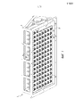
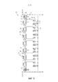
ФИГ. 1 представляет собой вид в изометрии узла панели прерывателя цепи согласно примерному варианту осуществления раскрытой концепции.FIG. 1 is an isometric view of a circuit breaker panel assembly according to an exemplary embodiment of the disclosed concept.
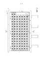
ФИГ. 2 представляет собой вид спереди узла панели прерывателя цепи согласно ФИГ. 1.FIG. 2 is a front view of a circuit breaker panel assembly according to FIG. one.
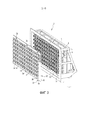
ФИГ. 3 представляет собой другой вид в изометрии панели прерывателя цепи согласно ФИГ. 1, с лицевой платой, выдвинутой наружу от панели прерывателя цепи.FIG. 3 is another isometric view of a circuit breaker panel according to FIG. 1, with a faceplate extending outward from the circuit breaker panel.
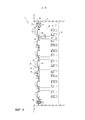
ФИГ. 4 представляет собой частичный поперечный разрез узла панели прерывателя цепи согласно ФИГ. 1-3, взятый вдоль линии 4-4 на ФИГ. 2.FIG. 4 is a partial cross-sectional view of a circuit breaker panel assembly according to FIG. 1-3 taken along line 4-4 in FIG. 2.
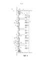
ФИГ. 5 представляет собой частичный поперечный разрез узла панели прерывателя цепи, включающего в себя другую примерную лицевую плату согласно другому варианту осуществления раскрытой концепции.FIG. 5 is a partial cross-sectional view of a circuit breaker panel assembly including another exemplary faceplate according to another embodiment of the disclosed concept.
ФИГ. 6 представляет собой частичный поперечный разрез узла панели прерывателя цепи, включающего в себя еще одну примерную лицевую плату согласно дополнительному примерному варианту осуществления раскрытой концепции.FIG. 6 is a partial cross-sectional view of a circuit breaker panel assembly including another exemplary faceplate according to a further exemplary embodiment of the disclosed concept.
ОПИСАНИЕ ПРЕДПОЧТИТЕЛЬНЫХ ВАРИАНТОВ ОСУЩЕСТВЛЕНИЯDESCRIPTION OF PREFERRED EMBODIMENTS
В целях настоящей работы, термин «множество» означает единицу или целое число, большее единицы (т.е. несколько).For the purposes of this work, the term “plurality” means a unit or an integer greater than one (ie, several).
В целях настоящей работы, утверждение, что две или более детали «связаны» вместе, означает, что детали соединены друг с другом непосредственно, либо соединены через одну или более промежуточных деталей.For the purposes of this work, the statement that two or more parts are “connected” together means that the parts are connected to each other directly, or connected through one or more intermediate parts.
В целях настоящей работы, термин «крепежный элемент» относится к любому подходящему соединяющему или затягивающему механизму, определенно включающему в себя, но не ограниченному винтами, болтами, гайками (например, помимо прочего, стопорные гайки) и их сочетаниями.For the purposes of this work, the term “fastener” refers to any suitable connecting or tightening mechanism that specifically includes but is not limited to screws, bolts, nuts (for example, but not limited to, lock nuts) and combinations thereof.
В целях настоящей работы, термин «переключающее электрическое устройство» относится к механизмам, используемым в электрических цепях, таких как, например, помимо прочего, прерыватели цепи, размыкатели, переключатели и контакторы. В целях настоящей работы, термин «исполнительный механизм» должен быть использован для части «переключающего электрического устройства», которая является переключаемой (например, помимо прочего, ручной управляющий элемент, тумблерный переключатель и т.д.).For the purposes of this work, the term “switching electrical device” refers to mechanisms used in electrical circuits, such as, for example, inter alia circuit breakers, circuit breakers, switches and contactors. For the purposes of this work, the term “actuator” should be used for the part of the “switching electrical device” that is switchable (for example, among other things, a manual control element, a toggle switch, etc.).
Раскрытая концепция описана в соотнесении со сверхминиатюрными или авиационными прерывателями цепи, хотя раскрытая концепция применима для широкого диапазона переключающих электрических устройств для широкого диапазона различных применений. Такие прерыватели цепи могут быть использованы, например, и помимо прочего, в авиационных электрических системах переменного тока (AC), обладающих типичной частотой примерно 400 Гц, но они также могут быть использованы в системах постоянного тока (DC). Также становится очевидным, что раскрытая концепция применима и для других типов панелей прерывателей цепи, включающих в себя панели прерывателей цепи, используемых в AC-системах, функционирующих при других частотах; для более крупных прерывателей цепи, таких как миниатюрные бытовые или коммерческие прерыватели цепи; и для широкого диапазона применений прерывателей цепи, таких как, например, помимо прочего, бытовые, коммерческие, промышленные, аэрокосмические и автомобильные. В качестве дополнительных неограничивающих примеров, возможно функционирование как при переменном токе (например, помимо прочего, 120, 220, 480-600 Вольт переменного тока) в широком диапазоне частот (например, помимо прочего, 50, 60, 120, 400 Гц, а также более высокие или более низкие частоты), так и при постоянном токе (например, помимо прочего, 42 Вольтах постоянного тока).The disclosed concept is described in relation to subminiature or aviation circuit breakers, although the disclosed concept is applicable to a wide range of switching electrical devices for a wide range of different applications. Such circuit breakers can be used, for example, and among other things, in aircraft electrical alternating current (AC) systems having a typical frequency of about 400 Hz, but they can also be used in direct current (DC) systems. It also becomes apparent that the disclosed concept is applicable to other types of circuit breaker panels, including circuit breaker panels used in AC systems operating at different frequencies; for larger circuit breakers, such as miniature domestic or commercial circuit breakers; and for a wide range of circuit breaker applications, such as, for example, but not limited to household, commercial, industrial, aerospace and automotive. As additional non-limiting examples, it is possible to operate as with alternating current (for example, among others, 120, 220, 480-600 volts AC) in a wide frequency range (for example, among other things, 50, 60, 120, 400 Hz, and higher or lower frequencies), and with direct current (for example, among other things, 42 Volts of direct current).
Обратимся к ФИГ. 1-4, где показана примерная панель переключающего электрического устройства, а точнее, примерная штепсельная панель 2 прерывателя цепи.Turning to FIG. 1-4, which shows an exemplary panel of a switching electrical device, and more specifically, an
Хотя примерная панель 2 не ограничена этим, она является особо пригодной для использования в аэрокосмических (например, авиационных) электрических системах. Штепсельная панель 2 прерывателя цепи включает в себя кожух 4, структуру 6 электрической шины, связанную с кожухом 4, множество первых штепсельных элементов 8 (показанных в виде линии невидимого контура на ФИГ. 4), связанных со структурой 6 электрической шины, и множество прерывателей 10 цепи (два ряда из пятнадцати прерывателей цепи и пять рядов из четырнадцати прерывателей цепи показаны в проиллюстрированном примерном варианте осуществления согласно ФИГ. 1-4, хотя может быть применимо любое подходящее количество).Although
Обратимся теперь в основном к ФИГ. 3 и 4, где каждый прерыватель 10 цепи включает в себя первую поверхность 12, исполнительный механизм в форме ручного управляющего элемента 14 (например, помимо прочего, нажимно-вытяжную ручку управления), расположенного от первой поверхности 12, и второй штепсельный элемент 16 (ФИГ. 4), расположенный напротив первой поверхности 12. Второй штепсельный элемент 16 каждого из прерывателей 10 цепи сопряжен с соответствующим одним из первых штепсельных элементов 8. Каждый второй штепсельный элемент 16 и соответствующий сопряженный первый штепсельный элемент 8 взаимодействуют для обеспечения одного из следующего: входной мощности (например, через линию) к соответствующему прерывателю цепи 10, или выходной мощности нагрузки (например, через нагрузку) от соответствующего прерывателя 10 цепи через структуру 6 электрической шины. Входная мощность может представлять собой, например, однофазную мощность переменного тока или одиночную входную мощность постоянного тока. В качестве альтернативы, входная мощность может представлять собой, например, трехфазную входную мощность переменного тока.Let us turn now mainly to FIG. 3 and 4, where each
Плоский элемент, такой как примерная лицевая плата 18, является разъемно связанным с кожухом 4. В примерных вариантах осуществления раскрытой концепции лицевая плата 18 образована из прессованной пластмассы, штампованного металла (например, помимо прочего, алюминия) или другого подходящего материала. Однако следует учитывать, что другие подходящие материалы могут быть использованы без отступления от объема раскрытой концепции.A flat member, such as an
Лицевая плата 18 включает в себя в целом плоский элемент 19 (ФИГ. 3), имеющий первую поверхность 20, противоположную вторую поверхность 22 и множество отверстий 24, расположенных сквозь первую поверхность 20 и противоположную вторую поверхность 22 лицевой платы 18. Ручной управляющий элемент 14 каждого из прерывателей 10 цепи проходит через соответствующее одно из отверстий 24. Первая поверхность 12 каждого прерывателя 10 цепи обычно сцепляется с противоположной второй поверхностью 22 лицевой платы 18 либо непосредственно, либо через кольцевое уплотнение 26 (как показано на ФИГ. 4) для поддержания сопряжения каждого из множества прерывателей 10 цепи с соответствующими первыми штепсельными элементами 8.The
Лицевая плата 18 дополнительно включает в себя множество наклоненных деталей 28, которые простираются от противоположной второй поверхности 22, как правило, у или вокруг соответствующего отверстия 24 из множества отверстий. Каждая наклоненная деталь включает в себя наклоненную поверхность 30, расположенную напротив второй поверхности 22 в целом плоского элемента 19 лицевой платы 18. Наклоненная поверхность 30 наклоненной детали 28 может включать в себя номенклатуру или другое средство индикации 32 (ФИГ. 2), такое как, например, помимо прочего, символы, буквы и/или цифры, задающие характеристику прерывателя цепи или цепи, в рамках который он установлен (например, помимо прочего, «шасси самолета», «закрылки», «топливо»). Средство индикации 32 может быть нанесено на (постоянно или временно) или образовано в или на лицевой плате.The
Как показано на поперечном разрезе согласно ФИГ. 4, наклоненная поверхность 30 расположена под ненулевым углом θ1 относительно в целом плоского элемента 19. Конкретный угол θ1 может быть определен, исходя из ориентации установки панели. В авиационных применениях, где панель 2 установлена в подвесной ориентации, так что лицевая плата 18, содержащая прерыватели 10 цепи, не ориентирована таким образом, чтобы обеспечивать пилоту или другому персоналу самолета идеальную линию прямой видимости, наклоненная деталь 28 может быть сконфигурирована под углом θ1, который обеспечивает пилоту или другому персоналу самолета оптимальную линию прямой видимости со средством индикации 32, обеспеченным на наклоненной поверхности 30.As shown in cross section according to FIG. 4, the
В примере, показанном на ФИГ. 1-4, угол θ1 составляет примерно 15°, однако могут быть использованы и другие углы, без отступления от объема раскрытой концепции. В зависимости от конкретного расположения, предпочтительными были углы в диапазоне от примерно 5° до примерно 60°. Следует учитывать, что в дополнение к обеспечению улучшенного угла обзора для средства индикации, варианты осуществления раскрытой концепции также обычно предусматривают размещение переключающих электрических устройств таким образом, чтобы они были сосредоточены на наклоненных поверхностях, на которых расположенное средство индикации требует меньше пространства панели, чем если бы средство индикации было отпечатано на стандартной плоской панели.In the example shown in FIG. 1-4, the angle θ 1 is approximately 15 °, but may be used and other angles without departing from the scope of the disclosed concept. Depending on the particular arrangement, angles in the range of about 5 ° to about 60 ° were preferred. It will be appreciated that in addition to providing an improved viewing angle for the indicating means, embodiments of the disclosed concept also typically provide for the placement of the switching electrical devices so that they are centered on inclined surfaces on which the located indicating means require less panel space than if the indication was printed on a standard flat panel.
Как показано в проиллюстрированном варианте осуществления согласно ФИГ. 1-4, многочисленные наклоненные детали могут быть соединены друг с другом, с образованием единой цельной наклоненной детали 34 (ФИГ. 1 и 2), которая может быть расположена вокруг более чем одного отверстия 24.As shown in the illustrated embodiment according to FIG. 1-4, numerous inclined parts can be connected to each other, with the formation of a single solid inclined parts 34 (FIGS. 1 and 2), which can be located around more than one
Лицевая плата 18 может включать в себя множество стягивающих крепежных элементов 36 (например, помимо прочего, четвертьоборотный крепежный элемент (элементы)), разъемно сцепляющих кожух 4 таким образом, что лицевая плата 18 является разъемно связанной с кожухом 4. Такое расположение легко позволяет проводить техническое обслуживание или осмотр одного или более различных прерывателей 10 цепи, внутренних контакторов, токочувствительных модулей и электронных быстросменных блоков (line replaceable units, LRU).The
На ФИГ. 5 показан частичный поперечный разрез другой примерной панели 40 в соответствии с другим вариантом осуществления раскрытой концепции. Панель 40 обычно имеет конструкцию аналогичную конструкции панели 2, ранее обсуждаемой применительно к ФИГ. 1-4, за исключением того, что панель 40 включает в себя лицевую плату 42 согласно другому примерному варианту осуществления раскрытой концепции, разъемно связанную с кожухом 4. Лицевая плата 42 имеет конструкцию, аналогичную конструкции лицевой платы 18, за исключением того, что лицевая плата 42 дополнительно включает в себя множество вторых наклоненных деталей 44, которые простираются от противоположной второй поверхности 22, как правило, у или вокруг соответствующего отверстия 24 из множества отверстий. Каждая вторая наклоненная деталь 44 включает в себя вторую наклоненную поверхность 46, расположенную напротив второй поверхности 22 в целом плоского элемента 19 лицевой платы 42. Вторая наклоненная поверхность 46 может включать в себя номенклатуру или другое средство индикации, такое как средство индикации 32 (ранее обсуждаемое). Вторая наклоненная поверхность 46 расположена под вторым ненулевым углом θ2 (отличным от ненулевого угла θ1) относительно в целом плоского элемента 19. Указанный второй угол θ2 может быть определен, исходя из ориентации расположения панели. В авиационных применениях, где панель 40 установлена в подвесной ориентации таким образом, что лицевая плата 42, содержащая прерыватели 10 цепи, не ориентирована таким образом, чтобы она обеспечивала пилоту или другому персоналу самолета идеальную линию прямой видимости, наклоненная деталь (детали) 28 может быть сконфигурирована под углом θ1, который обеспечивает пилоту или другому персоналу самолета оптимальную линию прямой видимости со средством индикации 32, обеспеченным на наклоненной поверхности (поверхностях) 30, тогда как вторая наклоненная деталь (детали) 44, которая могла бы быть расположена дальше от пилота или другого персонала самолета 44, может быть сконфигурирована под вторым углом θ2, который обеспечивает оптимальную линию прямой видимости со средством индикации (не пронумеровано), обеспеченным на второй наклоненной поверхности (поверхностях) 46.In FIG. 5 is a partial cross-sectional view of another exemplary panel 40 in accordance with another embodiment of the disclosed concept. Panel 40 typically has a design similar to that of
На ФИГ. 6 показан поперечный разрез еще одной примерной панели 50 в соответствии с другим вариантом осуществления раскрытой концепции. Панель 50 обычно имеет конструкцию, аналогичную конструкции панелей 2 и 40, ранее обсуждаемых применительно к ФИГ. 1-4 и 5, за исключением того, что панель 50 включает в себя лицевую плату 52 согласно еще одному примерному варианту осуществления раскрытой концепции, разъемно связанную с кожухом 4. Лицевая плата 52 имеет конструкцию, аналогичную конструкции лицевых плат 18 и 42, за исключением того, что лицевая плата 52 дополнительно включает в себя множество третьих наклоненных деталей 54, которые простираются от противоположной второй поверхности 22, как правило, у или вокруг соответствующего отверстия 24 из множества отверстий. Каждая третья наклоненная деталь 54 включает в себя третью наклоненную поверхность 56, расположенную напротив второй поверхности 22 в целом плоского элемента 19 лицевой платы 52. Третья наклоненная поверхность 56 может включать в себя номенклатуру или другое средство индикации, такое как средство индикации 32 (ранее обсуждаемое). Третья наклоненная поверхность 56 расположена под третьим ненулевым углом θ3 (отличным от ненулевого угла θ1 и второго ненулевого угла θ2) относительно в целом плоского элемента 19. Указанный третий угол θ3 может быть определен, исходя из ориентации установки панели. В авиационных применениях, где панель 50 установлена в подвесной ориентации таким образом, что лицевая плата 52, содержащая прерыватели 10 цепи, не ориентирована таким образом, чтобы она обеспечивала пилоту или другому персоналу самолета идеальную линию прямой видимости, наклоненная деталь (детали) 28 может быть сконфигурирована под углом θ1, который обеспечивает пилоту или другому персоналу самолета оптимальную линию прямой видимости со средством индикации 32, обеспеченным на наклоненной поверхности (поверхностях) 30, тогда как вторая наклоненная деталь (детали) 44, которая могла бы быть расположена далеко от пилота или другого персонала самолета, может быть сконфигурирована под вторым углом θ2, который обеспечивает оптимальную линию прямой видимости со средством индикации (не пронумеровано), обеспеченным на второй наклоненной поверхности (поверхностях) 46, а третья наклоненная деталь (детали) 54, которая может быть расположена еще дальше от пилота или другого персонала самолета, может быть сконфигурирована под третьим углом θ3, который обеспечивает оптимальную линию прямой видимости со средством индикации (не пронумеровано), обеспеченным на третьей наклоненной поверхности (поверхностях) 56.In FIG. 6 is a cross-sectional view of yet another
Тогда как здесь были описаны подробно конкретные варианты осуществления раскрытой концепции, специалисты в данной области техники должны учитывать, что различные модификации и альтернативы для этих деталей могут быть разработаны в свете общих учений согласно раскрытию. Например, предполагается, что одна или более из наклоненных поверхностей лицевой платы могут быть дополнительно наклонены таким образом, чтобы они были обращены к определенной точке, подобно сидениям в концертном зале. Дополнительно, предполагается, что одно или более рядов управляющих элементов или приводов могут быть расположены уступами относительно соседних рядов (т.е. не расположены в виде вертикальных столбцов), для улучшения одного или обоих из следующих свойств: видимости идентифицирующего средства индикации, или доступности таких управляющих элементов или приводов. Следовательно, конкретные расположения, раскрытые в настоящей работе, следует рассматривать лишь как иллюстративные, а не ограничивающие, а что же касается объема раскрытой концепции, которая здесь приведена, то он весь охвачен прилагаемыми пунктами формулы изобретения и любыми и всеми их эквивалентами.While specific embodiments of the disclosed concept have been described in detail here, those skilled in the art will appreciate that various modifications and alternatives for these details may be developed in light of the general teachings of the disclosure. For example, it is contemplated that one or more of the inclined surfaces of the faceplate may be further inclined so that they face a specific point, like seats in a concert hall. Additionally, it is contemplated that one or more rows of controls or actuators may be spaced relative to adjacent rows (i.e., not arranged as vertical columns), to improve one or both of the following: visibility of an identifying indicator, or the availability of such control elements or drives. Therefore, the specific locations disclosed in this work should be considered only as illustrative and not restrictive, and as for the scope of the concept disclosed, which is given here, it is all covered by the attached claims and any and all their equivalents.
Claims (29)
Applications Claiming Priority (3)
| Application Number | Priority Date | Filing Date | Title |
|---|---|---|---|
| US201261621162P | 2012-04-06 | 2012-04-06 | |
| US61/621,162 | 2012-04-06 | ||
| PCT/US2013/031829 WO2013151737A1 (en) | 2012-04-06 | 2013-03-15 | Faceplate for electrical switching apparatus panel and electrical switching apparatus panel including same |
Publications (2)
| Publication Number | Publication Date |
|---|---|
| RU2014144611A RU2014144611A (en) | 2016-05-27 |
| RU2625345C2 true RU2625345C2 (en) | 2017-07-13 |
Family
ID=48014363
Family Applications (1)
| Application Number | Title | Priority Date | Filing Date |
|---|---|---|---|
| RU2014144611A RU2625345C2 (en) | 2012-04-06 | 2013-03-15 | Facial board for the panel of switching electrical devices and panel of switching electrical device, including this facial board |
Country Status (8)
| Country | Link |
|---|---|
| US (1) | US9312674B2 (en) |
| EP (1) | EP2834891B1 (en) |
| JP (1) | JP6177308B2 (en) |
| CN (1) | CN104247181B (en) |
| BR (1) | BR112014024951B1 (en) |
| CA (1) | CA2868349C (en) |
| RU (1) | RU2625345C2 (en) |
| WO (1) | WO2013151737A1 (en) |
Families Citing this family (8)
| Publication number | Priority date | Publication date | Assignee | Title |
|---|---|---|---|---|
| FR3027166B1 (en) * | 2014-10-13 | 2016-12-09 | Crouzet Automatismes | CIRCUIT BREAKER PANEL |
| US10170264B2 (en) | 2015-03-06 | 2019-01-01 | Abb Schweiz Ag | Information display system for switching device, switching device, and method |
| US9870878B2 (en) | 2015-03-06 | 2018-01-16 | General Electric Company | Information display system for switching device, switching device, and method |
| USD803790S1 (en) | 2015-03-06 | 2017-11-28 | General Electric Company | Circuit breaker |
| GB2559795B (en) * | 2017-02-20 | 2020-01-22 | Ge Aviat Systems Ltd | Avionics power management panel and door assembly |
| GB2562771B (en) | 2017-05-25 | 2020-06-10 | Ge Aviat Systems Ltd | Power distribution system with snubber plate |
| CN107565410A (en) * | 2017-10-30 | 2018-01-09 | 现代重工(中国)电气有限公司 | A kind of easy-to-dismount switch cubicle |
| CN112466718B (en) * | 2020-11-03 | 2022-11-04 | 中国直升机设计研究所 | Circuit breaker device capable of being quickly disassembled and assembled and providing state display and assembling method |
Citations (4)
| Publication number | Priority date | Publication date | Assignee | Title |
|---|---|---|---|---|
| US2681966A (en) * | 1951-07-12 | 1954-06-22 | Fed Electric Prod Co | Circuit breaker enclosure and mounting |
| DE3246922A1 (en) * | 1982-12-18 | 1984-06-20 | Gebrüder Merten GmbH & Co KG, 5270 Gummersbach | Electrical surface-mounted installation switch having a marking plate |
| RU2285970C2 (en) * | 2002-05-23 | 2006-10-20 | Диджит Уайрлесс, Ллс | Key panels and key selectors |
| US20110235244A1 (en) * | 2010-03-29 | 2011-09-29 | Mills Patrick W | Plug-in circuit breaker assembly |
Family Cites Families (8)
| Publication number | Priority date | Publication date | Assignee | Title |
|---|---|---|---|---|
| JPH0511712U (en) * | 1991-07-18 | 1993-02-12 | 三菱電機株式会社 | Control center |
| JPH0997528A (en) * | 1995-09-29 | 1997-04-08 | Matsushita Electric Works Ltd | Switch plate |
| FR2807219B1 (en) * | 2000-03-31 | 2004-04-02 | Labinal | ELECTRICAL CONNECTION DEVICE AND POWER DISTRIBUTION DEVICE COMPRISING SAME |
| US7357667B2 (en) * | 2006-06-22 | 2008-04-15 | Adc Telecommunications, Inc. | Telecommunications patch |
| US7898787B2 (en) * | 2008-10-09 | 2011-03-01 | Adc Telecommunications, Inc. | Power panel with angled connectors |
| FR2945897B1 (en) * | 2009-05-19 | 2012-10-19 | Crouzet Automatismes | MULTIPLE CONNECTION ASSEMBLY OF REMOVABLE CUTTING DEVICES AND CUTTING DEVICE FOR CONNECTING WITH THE ASSEMBLY |
| EP2724433B1 (en) * | 2011-06-27 | 2019-03-20 | Labinal, LLC | Grounded circuit breaker panel electrical module and method for grounding same |
| US8649160B2 (en) * | 2012-02-07 | 2014-02-11 | Eaton Corporation | Plug-in circuit breaker assembly including insulative retainers |
-
2013
- 2013-03-15 CN CN201380017878.XA patent/CN104247181B/en active Active
- 2013-03-15 WO PCT/US2013/031829 patent/WO2013151737A1/en active Application Filing
- 2013-03-15 US US14/390,258 patent/US9312674B2/en active Active
- 2013-03-15 JP JP2015504588A patent/JP6177308B2/en active Active
- 2013-03-15 RU RU2014144611A patent/RU2625345C2/en active
- 2013-03-15 EP EP13713035.7A patent/EP2834891B1/en active Active
- 2013-03-15 CA CA2868349A patent/CA2868349C/en active Active
- 2013-03-15 BR BR112014024951-2A patent/BR112014024951B1/en active IP Right Grant
Patent Citations (4)
| Publication number | Priority date | Publication date | Assignee | Title |
|---|---|---|---|---|
| US2681966A (en) * | 1951-07-12 | 1954-06-22 | Fed Electric Prod Co | Circuit breaker enclosure and mounting |
| DE3246922A1 (en) * | 1982-12-18 | 1984-06-20 | Gebrüder Merten GmbH & Co KG, 5270 Gummersbach | Electrical surface-mounted installation switch having a marking plate |
| RU2285970C2 (en) * | 2002-05-23 | 2006-10-20 | Диджит Уайрлесс, Ллс | Key panels and key selectors |
| US20110235244A1 (en) * | 2010-03-29 | 2011-09-29 | Mills Patrick W | Plug-in circuit breaker assembly |
Also Published As
| Publication number | Publication date |
|---|---|
| US9312674B2 (en) | 2016-04-12 |
| BR112014024951A2 (en) | 2021-06-01 |
| CN104247181B (en) | 2017-02-22 |
| EP2834891B1 (en) | 2017-03-01 |
| RU2014144611A (en) | 2016-05-27 |
| CN104247181A (en) | 2014-12-24 |
| EP2834891A1 (en) | 2015-02-11 |
| WO2013151737A1 (en) | 2013-10-10 |
| JP2015514388A (en) | 2015-05-18 |
| US20150062786A1 (en) | 2015-03-05 |
| BR112014024951B1 (en) | 2021-08-24 |
| CA2868349C (en) | 2019-09-03 |
| CA2868349A1 (en) | 2013-10-10 |
| JP6177308B2 (en) | 2017-08-09 |
Similar Documents
| Publication | Publication Date | Title |
|---|---|---|
| RU2625345C2 (en) | Facial board for the panel of switching electrical devices and panel of switching electrical device, including this facial board | |
| US9197040B2 (en) | Plug-in circuit breaker assembly including insulative retainers | |
| EP2724432B1 (en) | Sealed plug-in circuit breaker assembly | |
| CA2844431C (en) | Electrical system and matrix assembly therefor | |
| WO2014033069A1 (en) | Withdrawable control compartment for switchgear | |
| EP2834892B1 (en) | Circuit breaker adaptor for plug-in circuit breaker panel | |
| KR20140032454A (en) | Star-delta wiring, in particular for a protective circuit on a mounting plate |