RU2624739C2 - Method and device for separation of material based on solid particles - Google Patents
Method and device for separation of material based on solid particles Download PDFInfo
- Publication number
- RU2624739C2 RU2624739C2 RU2014140222A RU2014140222A RU2624739C2 RU 2624739 C2 RU2624739 C2 RU 2624739C2 RU 2014140222 A RU2014140222 A RU 2014140222A RU 2014140222 A RU2014140222 A RU 2014140222A RU 2624739 C2 RU2624739 C2 RU 2624739C2
- Authority
- RU
- Russia
- Prior art keywords
- housing
- density
- fluid
- particles
- separation device
- Prior art date
Links
Images

Classifications
-
- B—PERFORMING OPERATIONS; TRANSPORTING
- B02—CRUSHING, PULVERISING, OR DISINTEGRATING; PREPARATORY TREATMENT OF GRAIN FOR MILLING
- B02C—CRUSHING, PULVERISING, OR DISINTEGRATING IN GENERAL; MILLING GRAIN
- B02C23/00—Auxiliary methods or auxiliary devices or accessories specially adapted for crushing or disintegrating not provided for in preceding groups or not specially adapted to apparatus covered by a single preceding group
- B02C23/08—Separating or sorting of material, associated with crushing or disintegrating
- B02C23/10—Separating or sorting of material, associated with crushing or disintegrating with separator arranged in discharge path of crushing or disintegrating zone
- B02C23/12—Separating or sorting of material, associated with crushing or disintegrating with separator arranged in discharge path of crushing or disintegrating zone with return of oversize material to crushing or disintegrating zone
-
- B—PERFORMING OPERATIONS; TRANSPORTING
- B02—CRUSHING, PULVERISING, OR DISINTEGRATING; PREPARATORY TREATMENT OF GRAIN FOR MILLING
- B02C—CRUSHING, PULVERISING, OR DISINTEGRATING IN GENERAL; MILLING GRAIN
- B02C23/00—Auxiliary methods or auxiliary devices or accessories specially adapted for crushing or disintegrating not provided for in preceding groups or not specially adapted to apparatus covered by a single preceding group
- B02C23/08—Separating or sorting of material, associated with crushing or disintegrating
- B02C23/14—Separating or sorting of material, associated with crushing or disintegrating with more than one separator
-
- B—PERFORMING OPERATIONS; TRANSPORTING
- B02—CRUSHING, PULVERISING, OR DISINTEGRATING; PREPARATORY TREATMENT OF GRAIN FOR MILLING
- B02C—CRUSHING, PULVERISING, OR DISINTEGRATING IN GENERAL; MILLING GRAIN
- B02C23/00—Auxiliary methods or auxiliary devices or accessories specially adapted for crushing or disintegrating not provided for in preceding groups or not specially adapted to apparatus covered by a single preceding group
- B02C23/18—Adding fluid, other than for crushing or disintegrating by fluid energy
- B02C23/20—Adding fluid, other than for crushing or disintegrating by fluid energy after crushing or disintegrating
- B02C23/22—Adding fluid, other than for crushing or disintegrating by fluid energy after crushing or disintegrating with recirculation of material to crushing or disintegrating zone
-
- B—PERFORMING OPERATIONS; TRANSPORTING
- B02—CRUSHING, PULVERISING, OR DISINTEGRATING; PREPARATORY TREATMENT OF GRAIN FOR MILLING
- B02C—CRUSHING, PULVERISING, OR DISINTEGRATING IN GENERAL; MILLING GRAIN
- B02C23/00—Auxiliary methods or auxiliary devices or accessories specially adapted for crushing or disintegrating not provided for in preceding groups or not specially adapted to apparatus covered by a single preceding group
- B02C23/18—Adding fluid, other than for crushing or disintegrating by fluid energy
- B02C23/24—Passing gas through crushing or disintegrating zone
-
- B—PERFORMING OPERATIONS; TRANSPORTING
- B07—SEPARATING SOLIDS FROM SOLIDS; SORTING
- B07B—SEPARATING SOLIDS FROM SOLIDS BY SIEVING, SCREENING, SIFTING OR BY USING GAS CURRENTS; SEPARATING BY OTHER DRY METHODS APPLICABLE TO BULK MATERIAL, e.g. LOOSE ARTICLES FIT TO BE HANDLED LIKE BULK MATERIAL
- B07B4/00—Separating solids from solids by subjecting their mixture to gas currents
- B07B4/08—Separating solids from solids by subjecting their mixture to gas currents while the mixtures are supported by sieves, screens, or like mechanical elements
-
- B—PERFORMING OPERATIONS; TRANSPORTING
- B07—SEPARATING SOLIDS FROM SOLIDS; SORTING
- B07B—SEPARATING SOLIDS FROM SOLIDS BY SIEVING, SCREENING, SIFTING OR BY USING GAS CURRENTS; SEPARATING BY OTHER DRY METHODS APPLICABLE TO BULK MATERIAL, e.g. LOOSE ARTICLES FIT TO BE HANDLED LIKE BULK MATERIAL
- B07B9/00—Combinations of apparatus for screening or sifting or for separating solids from solids using gas currents; General arrangement of plant, e.g. flow sheets
- B07B9/02—Combinations of similar or different apparatus for separating solids from solids using gas currents
-
- B—PERFORMING OPERATIONS; TRANSPORTING
- B02—CRUSHING, PULVERISING, OR DISINTEGRATING; PREPARATORY TREATMENT OF GRAIN FOR MILLING
- B02C—CRUSHING, PULVERISING, OR DISINTEGRATING IN GENERAL; MILLING GRAIN
- B02C15/00—Disintegrating by milling members in the form of rollers or balls co-operating with rings or discs
- B02C2015/002—Disintegrating by milling members in the form of rollers or balls co-operating with rings or discs combined with a classifier
Abstract
Description
ПРЕДПОСЫЛКИ СОЗДАНИЯ ИЗОБРЕТЕНИЯBACKGROUND OF THE INVENTION
[001] Настоящее изобретение относится к устройству и способу разделения материала на основе твердых частиц. В частности, настоящее изобретение относится к такому устройству и способу, которые предназначены для разделения минералов по плотности.[001] The present invention relates to an apparatus and method for separating particulate material. In particular, the present invention relates to such a device and method, which are designed to separate minerals by density.
[002] Согласно предпочтительному, но не ограничивающему варианту осуществления настоящее изобретение относится к конкретному процессу удаления материала на основе минеральных частиц из рециркулирующего вещества в размалывающей машине по плотности. Конкретный процесс включает начальный отбор частиц в зависимости от размера с помощью процесса просеивания для выбора материала на основе твердых частиц, которые были измельчены до размера, при котором композиция близка к однородной. Затем выполняют второй процесс, предназначенный для разделения материала с низкой плотностью от материала с высокой плотностью. Материал с низкой плотностью может быть подан обратно в мельницу до тех пор, пока компонент с высокой плотностью не будет удален, или материал с низкой плотностью может быть удален во время подачи компонента с высокой плотностью обратно в мельницу.[002] According to a preferred, but non-limiting embodiment, the present invention relates to a specific process for removing material based on mineral particles from a recycle material in a density milling machine. A particular process involves the initial selection of particles depending on size using a sieving process to select material based on solid particles that have been ground to a size at which the composition is close to uniform. Then, a second process is performed to separate the low density material from the high density material. The low density material can be fed back to the mill until the high density component is removed, or the low density material can be removed while the high density component is fed back to the mill.
ОПИСАНИЕ УРОВНЯ ТЕХНИКИDescription of the level of technology
[003] Ссылка на любой документ из уровня техники (или информацию, полученную из него) или на любой известный материал, приведенная в настоящем документе, не представляет собой и не должна рассматриваться как признание, или подтверждение, или любая форма предположения того, что документ из уровня техники (или информация, полученная из него) или известный материал образует часть общих знаний в области техники, к которой относится настоящее изобретение.[003] A reference to any document of the prior art (or information derived from it) or to any known material provided herein does not constitute and should not be construed as recognition, or confirmation, or any form of assumption that the document from the prior art (or information derived from it) or known material forms part of the general knowledge of the technical field to which the present invention relates.
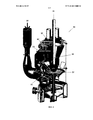
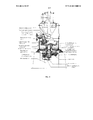
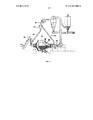
[004] На фиг. 1 показана традиционная мельница [80] с вертикальным шпинделем для размола угля, известняка или других материалов. Сырье подают вниз в центр мельницы [81] в секцию [82] размола, где оно измельчается на маленькие частицы. Обычно эти частицы транспортируются [83] воздухом внутри мельницы в сортировочное устройство [84], в котором частицы [86] большего размера отделяются от мелких частиц [87] и возвращаются в процесс [82] размалывания для дальнейшего размалывания. В результате возникает рециркулирующая нагрузка крупных частиц, переносимых из секции [82] размола мельницы в сортировочную секцию [84], а затем возвращаются обратно в секцию [82] размола. Обычно размалывание осуществляют с помощью кругов [85] или шаров, расположенных ниже в мельнице, и газ, обычно воздух, обдувает [88] секцию [82] размола, захватывая размолотый материал в сортировочное устройство [84], обычно расположенное вверху мельницы. Крупные частицы, отброшенные в сортировочном устройстве [84], обычно возвращаются в нижнюю секцию [82] размола через желоб [86] для отброшенных частиц. Стандартный пример мельницы с вертикальным шпинделем показан на фиг. 1, и получаемый процесс рециркуляции крупных частиц отображен на фиг. 2. На фиг. 3 более подробно показана обычная мельница с вертикальным шпинделем.[004] FIG. 1 shows a traditional mill [80] with a vertical spindle for grinding coal, limestone or other materials. The feed is fed down to the center of the mill [81] into the grinding section [82], where it is crushed into small particles. Typically, these particles are transported [83] by air inside the mill to a sorting device [84], in which larger particles [86] are separated from small particles [87] and returned to the grinding process [82] for further grinding. As a result, a recycle load of large particles arises from the mill grinding section [82] to the sorting section [84], and then returns to the grinding section [82]. Milling is usually carried out using circles [85] or balls located lower in the mill, and gas, usually air, blows through [88] the grinding section [82], capturing the milled material into a sorting device [84], usually located at the top of the mill. Large particles discarded in the screener [84] typically return to the lower grinding section [82] through a chute [86] for discarded particles. A standard example of a vertical spindle mill is shown in FIG. 1, and the resulting large particle recycling process is depicted in FIG. 2. In FIG. 3 shows in more detail a conventional mill with a vertical spindle.
[005] Такой же процесс протекает в обычной шаровой мельнице [100], примеры которой показаны на фиг. 5 и 6. В шаровой мельнице сырье [81] подается на сторону с вращающимся барабаном [90]. С помощью больших шаров [95] измельчают сырье на небольшие частицы. Частицы транспортируются [93] воздухом в сортировочное устройство [94], где крупные частицы [96] отделяются от мелких частиц [97] и возвращаются в процесс [82] размалывания для дальнейшего размалывания. Снова в шаровой мельнице газ обдувает [98] секцию [82] размола, захватывая размолотый материал в сортировочное устройство [94], которое в данном случае расположено отдельно от размалывающего устройства. Крупные частицы, отброшенные в сортировочное устройство [94], возвращаются в секцию [82] размола по желобу [96] для отброшенных частиц.[005] The same process takes place in a conventional ball mill [100], examples of which are shown in FIG. 5 and 6. In a ball mill, raw materials [81] are fed to the rotary drum side [90]. Using large balls [95], the raw materials are crushed into small particles. Particles are transported [93] by air to a sorting device [94], where large particles [96] are separated from small particles [97] and returned to the grinding process [82] for further grinding. Again, in a ball mill, gas blows through [98] the grinding section [82], capturing the ground material into a sorting device [94], which in this case is located separately from the grinding device. Large particles discarded into the screening device [94] are returned to the grinding section [82] along the groove [96] for the discarded particles.
[006] Исходное сырье, изначально поданное в мельницу [81], обычно состоит из конгломерата разных минеральных примесей, связанных вместе другим основным минералом. Обычными примерами такого конгломерата являются уголь и известняк, где различные компоненты примесей могут содержать минералы, такие как кварц (песок), пириты (железо), кальций и/или глинозем (в составе глины), которые внедрены в основной минерал в виде твердых частиц или небольших комков отдельных примесей. В случае с углем первичным минералом является углерод, тогда как в случае с известняком основным минералом является карбонат кальция. В процессе размола сырье измельчается с высвобождением любых частиц, образующих конгломераты в первичном минерале. Так, в случае угля частицы песка, железа и глины образуются дополнительно к частицам углерода.[006] The feedstock initially fed to the mill [81] usually consists of a conglomerate of various mineral impurities bound together by another main mineral. Common examples of such a conglomerate are coal and limestone, where various components of the impurities may contain minerals such as quartz (sand), pyrites (iron), calcium and / or alumina (in clay), which are embedded in the main mineral in the form of solid particles or small lumps of individual impurities. In the case of coal, the primary mineral is carbon, while in the case of limestone, the main mineral is calcium carbonate. In the process of grinding, the raw materials are crushed with the release of any particles forming conglomerates in the primary mineral. So, in the case of coal, particles of sand, iron and clay are formed in addition to carbon particles.
[007] Разделение компонентов минералов можно осуществлять на основе различных физических или химических свойств, например, на основе удельного электрического сопротивления или растворимости. В случае угля, если необходимо отделять углерод от других минералов с низкой плотностью, например глинозема, кальция или глины, для отделения углерода с низким удельным сопротивлением от глинозема или кальция с высоким удельным сопротивлением можно применять электростатический сепаратор. Электростатические сепараторы, как известно, применяют в области разработки минеральных месторождений для разделения ценных минералов, которые можно вводить в используемый в настоящее время процесс удаления минералов для увеличения степени разделения материала как с низкой, так и с высокой плотностью. Дополнительное разделение на основе растворимости является другой опцией для дополнительной обработки материала с низкой или высокой плотностью. При промывании извлеченных минералов удаляются растворимые компоненты, которые впоследствии, при необходимости, могут быть восстановлены путем выпаривания воды.[007] Separation of mineral components can be performed based on various physical or chemical properties, for example, based on electrical resistivity or solubility. In the case of coal, if it is necessary to separate carbon from other minerals with a low density, for example alumina, calcium or clay, an electrostatic separator can be used to separate carbon with a low resistivity from alumina or calcium with a high resistivity. Electrostatic separators are known to be used in the field of development of mineral deposits for the separation of valuable minerals, which can be introduced into the currently used process for removing minerals to increase the degree of separation of material with both low and high density. Additional solubility separation is another option for additional processing of low or high density material. When washing the extracted minerals, soluble components are removed, which subsequently, if necessary, can be restored by evaporation of water.
[008] Задачей всех процессов разделения, известных из уровня техники, является удаление примесей или подобного для эффективного повышения концентрации требуемого минерала.[008] The objective of all separation processes known in the art is to remove impurities or the like in order to effectively increase the concentration of the desired mineral.
СУЩНОСТЬ ИЗОБРЕТЕНИЯSUMMARY OF THE INVENTION
[009] Целью настоящего изобретения является обеспечение усовершенствованного или, по меньшей мере, альтернативного устройства и способа разделения материала на основе твердых частиц.[009] An object of the present invention is to provide an improved or at least alternative device and method for separating particulate material.
[0010] Также целью настоящего изобретения является обеспечение разделительного устройства для разделения и процесса разделения, обеспечивающих разделение материала на основе минеральных или других твердых частиц по плотности.[0010] It is also an object of the present invention to provide a separation device for separation and a separation process for separating material based on mineral or other solid particles in density.
[0011] В более широком смысле настоящее изобретение обеспечивает разделительное устройство для разделения материала на основе твердых частиц, содержащее:[0011] More generally, the present invention provides a separation device for separating particulate material, comprising:
корпус;housing;
впускное отверстие для твердых частиц, предназначенное для подачи указанного материала на основе твердых частиц в указанный корпус;particulate inlet for supplying said particulate material to said housing;
впускное отверстие для текучей среды, предназначенное для подачи текучей среды в указанный корпус; иa fluid inlet for supplying a fluid to said body; and
выпускное отверстие, предназначенное для выпуска материала на основе твердых частиц с заданной плотностью из указанного корпуса.an outlet designed to discharge material based on solid particles with a given density from the specified housing.
[0012] Предпочтительно указанное впускное отверстие для текучей среды предназначено для подачи указанного материала на основе твердых частиц в нижнюю часть указанного корпуса.[0012] Preferably, said fluid inlet is for supplying said particulate material to the lower part of said casing.
[0013] Также предпочтительно указанное выпускное отверстие предназначено для выпуска материала на основе твердых частиц с заданной плотностью из верхней части указанного корпуса.[0013] Also preferably, said outlet is for discharging particulate material with a predetermined density from an upper part of said enclosure.
[0014] Также предпочтительно указанное выпускное отверстие предназначено для выпуска материала на основе твердых частиц с заданной плотностью из нижней части указанного корпуса.[0014] Also preferably, said outlet is for discharging particulate material with a predetermined density from the bottom of said enclosure.
[0015] Также предпочтительно указанное выпускное отверстие предназначено для выпуска материала на основе твердых частиц с заданной плотностью из верхней части указанного корпуса, и указанное устройство дополнительно содержит второе выпускное отверстие, которое предназначено для выпуска материала на основе твердых частиц со второй заданной плотностью из нижней части указанного корпуса.[0015] Also preferably, said outlet is for discharging particulate material with a predetermined density from an upper part of said body, and said apparatus further comprises a second outlet that is for discharging particulate material with a second predetermined density from a bottom specified body.
[0016] Также предпочтительно указанное впускное отверстие для твердых частиц содержит по меньшей мере одно сито для сортировки по размерам.[0016] Also preferably, said particulate inlet comprises at least one sieve for sizing.
[0017] Также предпочтительно указанный корпус разделен на секции.[0017] Also preferably, said body is divided into sections.
[0018] Также предпочтительно указанный корпус содержит по меньшей мере одно распределительное сито, которое участвует в распределении текучей среды, протекающей через указанное сито.[0018] Also preferably, said housing comprises at least one distribution sieve that is involved in the distribution of fluid flowing through said sieve.
[0019] Также предпочтительно указанное устройство содержит несколько впускных отверстий для текучей среды.[0019] Also preferably, said device comprises several fluid inlets.
[0020] Также предпочтительно указанное впускное отверстие для текучей среды расположено под перфорированной пластиной, которая проходит через корпус.[0020] Also preferably, said fluid inlet is located beneath a perforated plate that extends through the housing.
[0021] В более широком смысле настоящее изобретение обеспечивает многоступенчатое разделительное устройство для разделения материала на основе твердых частиц, содержащее по меньшей мере два указанных разделительных устройства, описанных выше, причем указанное выпускное отверстие первого разделительного устройства предназначено для подачи материала на основе твердых частиц в указанное впускное отверстие для твердых частиц второго разделительного устройства.[0021] In a broader sense, the present invention provides a multi-stage separation device for separating particulate matter, comprising at least two of the separation apparatus described above, wherein said outlet of the first separation apparatus is for conveying particulate material to said an inlet for solids of the second separation device.
[0022] Предпочтительно сито для сортировки по размерам расположено между указанным выпускным отверстием первого разделительного устройства и указанным впускным отверстием для частиц второго разделительного устройства.[0022] Preferably, the sieve for sizing is located between the specified outlet of the first separation device and the specified inlet for particles of the second separation device.
[0023] В более широком смысле настоящее изобретение обеспечивает способ разделения материала на основе твердых частиц с применением разделительного устройства, содержащего:[0023] In a broader sense, the present invention provides a method for separating particulate material using a separation device comprising:
корпус;housing;
впускное отверстие для твердых частиц, предназначенное для подачи указанного материала на основе твердых частиц в указанный корпус;particulate inlet for supplying said particulate material to said housing;
впускное отверстие для текучей среды, предназначенное для подачи текучей среды в указанный корпус;a fluid inlet for supplying a fluid to said body;
выпускное отверстие, предназначенное для выпуска материала на основе твердых частиц с заданной плотностью из указанного корпуса;an outlet for discharging material based on solid particles with a predetermined density from said body;
причем способ включает этапы:moreover, the method includes the steps of:
подачи материала на основе твердых частиц в указанный корпус через указанное впускное отверстие для твердых частиц,supplying particulate material to said body through said particulate inlet,
подачи указанной текучей среды в указанный корпус через указанное впускное отверстие для текучей среды, иsupplying said fluid to said body through said fluid inlet; and
выпуска материала на основе твердых частиц с заданной плотностью из указанного корпуса через указанное выпускное отверстие.the release of material based on solid particles with a given density from the specified body through the specified outlet.
[0024] В более широком смысле настоящее изобретение обеспечивает разделительное устройство для разделения материала на основе твердых частиц, предназначенное для применения совместно с размалывающим или измельчающим устройством, причем разделительное устройство содержит:[0024] In a broader sense, the present invention provides a separation device for separating material based on solid particles, intended for use in conjunction with a grinding or grinding device, the separation device comprising:
корпус;housing;
впускное отверстие для твердых частиц, предназначенное для подачи указанного материала на основе твердых частиц в указанный корпус;particulate inlet for supplying said particulate material to said housing;
впускное отверстие для текучей среды, предназначенное для подачи текучей среды в указанный корпус; иa fluid inlet for supplying a fluid to said body; and
выпускное отверстие, предназначенное для выпуска материала на основе твердых частиц с заданной плотностью из указанного корпуса.an outlet designed to discharge material based on solid particles with a given density from the specified housing.
[0025] Предпочтительно указанное впускное отверстие для текучей среды предназначено для подачи указанного материала на основе твердых частиц в нижнюю часть указанного корпуса.[0025] Preferably, said fluid inlet is for supplying said particulate material to the lower part of said casing.
[0026] Также предпочтительно указанное выпускное отверстие предназначено для выпуска материала на основе твердых частиц с заданной плотностью из верхней части указанного корпуса.[0026] Also preferably, said outlet is for discharging particulate material with a predetermined density from an upper part of said enclosure.
[0027] Также предпочтительно указанное выпускное отверстие предназначено для выпуска материала на основе твердых частиц с заданной плотностью из нижней части указанного корпуса.[0027] Also preferably, said outlet is for discharging particulate material with a predetermined density from the bottom of said enclosure.
[0028] Также предпочтительно указанное выпускное отверстие предназначено для выпуска материала на основе твердых частиц с заданной плотностью из верхней части указанного корпуса, и указанное устройство дополнительно содержит второе выпускное отверстие, которое предназначено для выпуска материала на основе твердых частиц со второй заданной плотностью из нижней части указанного корпуса.[0028] Also preferably, said outlet is for discharging particulate material with a predetermined density from an upper part of said body, and said apparatus further comprises a second outlet that is for discharging particulate material with a second predetermined density from a bottom specified body.
[0029] Также предпочтительно указанное впускное отверстие для твердых частиц содержит по меньшей мере одно сито для сортировки по размерам.[0029] Also preferably, said particulate inlet comprises at least one sieve for sizing.
[0030] Также предпочтительно устройство разделения разделено на секции.[0030] It is also preferred that the separation device is partitioned.
[0031] Также предпочтительно указанный корпус устройства содержит по меньшей мере одно распределительное сито, которое участвует в распределении текучей среды, протекающей через указанное сито.[0031] It is also preferred that said device housing comprises at least one distribution sieve that is involved in the distribution of fluid flowing through said sieve.
[0032] Также предпочтительно указанное устройство содержит несколько впускных отверстий для текучей среды.[0032] Also preferably, said device comprises several fluid inlets.
[0033] Также предпочтительно указанное впускное отверстие для текучей среды расположено под перфорированной пластиной, которая проходит через корпус.[0033] Also preferably, said fluid inlet is located under a perforated plate that extends through the housing.
[0034] В более широком смысле настоящее изобретение обеспечивает многоступенчатое разделительное устройство для разделения материала на основе твердых частиц, содержащее по меньшей мере два разделительных устройства, описанных выше, причем указанное выпускное отверстие первого разделительного устройства предназначено для подачи материала на основе твердых частиц в указанное впускное отверстие для твердых частиц второго разделительного устройства.[0034] More generally, the present invention provides a multi-stage separation device for separating particulate material, comprising at least two separation devices described above, wherein said outlet of the first separation device is for feeding particulate material to said inlet hole for solid particles of the second separation device.
[0035] Предпочтительно сито для сортировки по размерам расположено между указанным выпускным отверстием первого разделительного устройства и указанным впускным отверстием для частиц второго разделительного устройства.[0035] Preferably, the sieve for sizing is located between the specified outlet of the first separation device and the specified inlet for particles of the second separation device.
[0036] Также предпочтительно устройство или аппарат установлен в мельнице с вертикальным шпинделем.[0036] It is also preferred that the device or apparatus is mounted in a mill with a vertical spindle.
[0037] В более широком смысле настоящее изобретение обеспечивает способ разделения материала на основе твердых частиц в размалывающем или измельчающем устройстве с применением разделительного устройства, содержащего:[0037] More broadly, the present invention provides a method for separating particulate material in a grinding or grinding device using a separation device comprising:
корпус;housing;
впускное отверстие для твердых частиц, предназначенное для подачи указанного материала на основе твердых частиц в указанный корпус;particulate inlet for supplying said particulate material to said housing;
впускное отверстие для текучей среды, предназначенное для подачи текучей среды в указанный корпус;a fluid inlet for supplying a fluid to said body;
выпускное отверстие, предназначенное для выпуска материала на основе твердых частиц с заданной плотностью из указанного корпуса;an outlet for discharging material based on solid particles with a predetermined density from said body;
причем способ включает этапы:moreover, the method includes the steps of:
подачи материала на основе твердых частиц в указанный корпус через указанное впускное отверстие для твердых частиц,supplying particulate material to said body through said particulate inlet,
подачи текучей среды в указанный корпус через указанное впускное отверстие для текучей среды, иsupplying fluid to said body through said fluid inlet; and
выпуск твердых частиц с заданной плотностью из указанного корпуса через указанное выпускное отверстие.the release of solid particles with a given density from the specified housing through the specified outlet.
КРАТКОЕ ОПИСАНИЕ ГРАФИЧЕСКИХ МАТЕРИАЛОВBRIEF DESCRIPTION OF GRAPHIC MATERIALS
[0038] Настоящее изобретение станет более понятным после прочтения приведенного ниже подробного описания предпочтительных, но не ограничивающих вариантов осуществления, описанных со ссылкой на прилагаемые графические материалы, где:[0038] The present invention will become more apparent after reading the following detailed description of preferred, but not limiting embodiments described with reference to the accompanying drawings, where:
[0039] на фиг. 1 представлен вид в разрезе обычной мельницы с вертикальным шпинделем из уровня техники;[0039] in FIG. 1 is a sectional view of a conventional mill with a vertical spindle from the prior art;
[0040] на фиг. 2 представлена мельница с вертикальным шпинделем из уровня техники, в которой происходит процесс рециркуляции крупных частиц;[0040] in FIG. 2 shows a mill with a vertical spindle from the prior art, in which the process of recycling large particles;
[0041] на фиг. 3 представлена мельница с вертикальным шпинделем из уровня техники;[0041] in FIG. 3 shows a mill with a vertical spindle from the prior art;
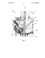
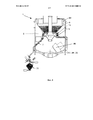
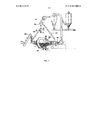
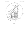
[0042] на фиг. 4 представлено изобретение, установленное в мельнице с вертикальным шпинделем, включая отверстие для впуска псевдоожижающего воздуха и выпускное отверстие для твердых частиц;[0042] in FIG. 4 illustrates an invention installed in a mill with a vertical spindle, including a fluidizing air inlet and a solids outlet;
[0043] на фиг. 5 представлена обычная шаровая мельница из уровня техники;[0043] in FIG. 5 shows a conventional ball mill of the prior art;
[0044] на фиг. 6 представлена обычная шаровая мельница из уровня техники с потоком различных частиц;[0044] in FIG. 6 shows a conventional ball mill of the prior art with a flow of various particles;
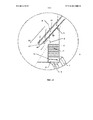
[0045] на фиг. 7 показано изобретение, установленное в шаровой мельнице;[0045] in FIG. 7 shows an invention installed in a ball mill;
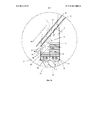
[0046] на фиг. 8 представлен двухступенчатый вариант осуществления настоящего изобретения, содержащий несколько распределительных сит, сит для сортировки по размерам над впускным отверстием для частиц и сито для сортировки по размерам между ступенями;[0046] in FIG. 8 illustrates a two-stage embodiment of the present invention, comprising several distribution sieves, size sieves above the particle inlet, and a size sieve between the steps;
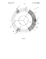
[0047] на фиг. 9 представлен вид сверху разделенного на секции варианта осуществления настоящего изобретения;[0047] in FIG. 9 is a plan view of a sectioned embodiment of the present invention;
[0048] на фиг. 10 представлен многоступенчатый вариант осуществления, содержащий несколько отверстий для впуска воздуха, несколько распределительных сит и сит для сортировки по размерам над впускным отверстием для частиц, а также между ступенями; и[0048] in FIG. 10 shows a multi-stage embodiment comprising several air inlet openings, several distribution sieves and size sieves above the particle inlet, as well as between steps; and
[0049] на фиг. 11 представлен одноступенчатый вариант осуществления, содержащий блок распределения текучей среды и перфорированную пластину, несколько распределительных сит и сит для сортировки над впускным отверстием для частиц.[0049] in FIG. 11 depicts a single-stage embodiment comprising a fluid distribution unit and a perforated plate, multiple distribution sieves and sorting screens over a particle inlet.
ПОДРОБНОЕ ОПИСАНИЕ ПРЕДПОЧТИТЕЛЬНОГО ВАРИАНТА ОСУЩЕСТВЛЕНИЯDETAILED DESCRIPTION OF THE PREFERRED EMBODIMENT
[0050] На графических материалах одинаковыми позициями обозначены одинаковые элементы, если не указано другое.[0050] On graphical materials, the same reference numbers denote the same elements, unless otherwise indicated.
[0051] На фиг. 4 показан предпочтительный вариант осуществления настоящего изобретения, установленный в мельнице [1] с вертикальным шпинделем, а на фиг. 7 показан предпочтительный вариант осуществления, установленный в шаровой мельнице [110]. Разделительное устройство [2] подробно показано на фиг. 8. Оно содержит корпус [3], впускное отверстие [4] для твердых частиц, впускное отверстие [5] для текучей среды и выпускное отверстие [6]. Корпус [3] обычно изготовлен из стали, но могут использоваться другие подходящие материалы или композиты. Твердые частицы, обычно, кроме прочего, уголь, известняк или другие минералы, поступают в устройство [2] через впускное отверстие [4] для твердых частиц. Текучая среда, обычно воздух, которой, однако, может быть любая другая текучая среда с соответствующими свойствами, и которая не вступает в реакцию с твердыми частицами, поступает в устройство [2] через впускное отверстие [5] для текучей среды. Текучая среда может находиться под давлением, и, как понятно специалисту в области техники, оптимальное давление можно определить на основании плотностей твердых частиц, объема корпуса, разделяемого целевого материала и других факторов, так что между твердыми частицами и текучей средой происходит соответствующее смешивание или псевдоожижение. Твердые частицы с заданной плотностью покидают устройство [2] через выпускное отверстие [6]. Например, если основным материалом является уголь, могут собираться частицы с высокой плотностью, такие как кварц и пириты, тогда как частицы с низкой плотностью, такие как углерод, покидают устройство.[0051] FIG. 4 shows a preferred embodiment of the present invention installed in a mill [1] with a vertical spindle, and in FIG. 7 shows a preferred embodiment installed in a ball mill [110]. The separation device [2] is shown in detail in FIG. 8. It comprises a housing [3], an inlet [4] for particulate matter, an inlet [5] for a fluid, and an outlet [6]. The housing [3] is usually made of steel, but other suitable materials or composites may be used. Particulate matter, usually, among other things, coal, limestone or other minerals, enters the device [2] through the inlet [4] for particulate matter. A fluid medium, usually air, which, however, can be any other fluid medium with the corresponding properties, and which does not react with solid particles, enters the device [2] through the fluid inlet [5]. The fluid may be under pressure, and, as one skilled in the art will understand, the optimal pressure can be determined based on the density of the solid particles, the volume of the body, the target material to be separated, and other factors, so that appropriate mixing or fluidization occurs between the solid particles and the fluid. Solid particles with a given density leave the device [2] through the outlet [6]. For example, if the main material is coal, particles with a high density, such as quartz and pyrites, can collect, while particles with a low density, such as carbon, leave the device.
[0052] Согласно предпочтительному варианту осуществления впускное отверстие [5] для текучей среды расположено таким образом, что текучая среда поступает в нижнюю часть корпуса [3] устройства. Это обеспечивает подъем текучей среды через твердые частицы, обеспечивая их псевдоожижение. После этого материал с низкой плотностью может оседать в верхней части корпуса [3], тогда как материал с высокой плотностью перемещается вниз.[0052] According to a preferred embodiment, the fluid inlet [5] is positioned so that the fluid enters the lower part of the device casing [3]. This allows fluid to rise through the solid particles, providing fluidization. After that, a material with a low density can settle in the upper part of the housing [3], while a material with a high density moves down.
[0053] Выпускное отверстие [6] расположено таким образом, что твердые частицы с заданной плотностью выходят из верхней части корпуса [3] устройства. Альтернативно выпускное отверстие [7] может быть расположено таким образом, что твердые частицы с заданной плотностью выходят из нижней части корпуса [3] устройства. Согласно показанному варианту осуществления устройство [2] может содержать как верхнее выпускное отверстие [6], так и нижнее выпускное отверстие [7]. На фиг. 4 показан вариант осуществления с верхним выпускным отверстием [6], через которое материал может возвращаться в процесс [82] размалывания, и нижним выпускным отверстием [7], сообщающимся с бункером [31] для отброшенных из мельницы частиц. Этот материал можно полностью изъять из процесса размалывания или подвергнуть дальнейшей обработке.[0053] The outlet [6] is positioned so that solid particles with a given density exit from the upper part of the device housing [3]. Alternatively, the outlet [7] can be positioned so that solid particles with a given density exit the bottom of the device [3]. According to the shown embodiment, the device [2] may comprise both an upper outlet [6] and a lower outlet [7]. In FIG. 4 shows an embodiment with an upper outlet [6] through which material can be returned to the milling process [82] and a lower outlet [7] in communication with the hopper [31] for particles discarded from the mill. This material can be completely removed from the grinding process or subjected to further processing.
[0054] Впускное отверстие [4] для твердых частиц может содержать по меньшей мере одно сито [8] для сортировки по размерам. Согласно показанному варианту осуществления также присутствует второе сито [9] для сортировки. В случае угля первое сито [8] для сортировки может пропускать [41] частицы меньше 10 мм, а второе сито [9] может пропускать [42] частицы меньше 3 мм. Это стандартные значения, а разделяемые размеры определяются в соответствии с конкретной хранящейся композицией материала. Материал, слишком крупный для первого сита [43] или слишком крупный для второго сита [44], как правило, возвращается в процесс [82] размалывания.[0054] The particulate inlet [4] may comprise at least one sieve [8] for sizing. According to the shown embodiment, there is also a second screen [9] for sorting. In the case of coal, the first sieve [8] for sorting can pass [41] particles less than 10 mm, and the second sieve [9] can pass [42] particles less than 3 mm. These are standard values, and the dimensions to be shared are determined according to the particular stored composition of the material. Material that is too large for the first sieve [43] or too large for the second sieve [44] usually returns to the grinding process [82].
[0055] На фиг. 9 показан вариант осуществления разделительного устройства [2], разделенного на секции посредством сплошных разделительных перегородок [10] и перфорированных разделительных перегородок [22]. Разделение разделительного устройства [2] на секции посредством сплошных разделительных перегородок [10] повышает эффективность за счет ограничения объема псевдоожижаемого материала. Каждая секция имеет отдельное выпускное отверстие [7], и меньший размер улучшает распределение текучей среды и предотвращает скопление материала с высокой или низкой плотностью на концах устройства.[0055] In FIG. 9 shows an embodiment of a separation device [2] divided into sections by continuous separation partitions [10] and perforated separation partitions [22]. The separation of the separation device [2] into sections by means of continuous separation partitions [10] increases efficiency by limiting the volume of fluidized material. Each section has a separate outlet [7], and a smaller size improves the distribution of the fluid and prevents the accumulation of material with high or low density at the ends of the device.
[0056] Предпочтительный вариант осуществления также содержит сита для пузырьков псевдоожиженного слоя или распределительные сита [11], которые способствуют распределению потока текучей среды по корпусу [3]. Равномерный поток текучей среды по устройству обеспечивает более эффективную плотность разделения, так как более интенсивные потоки в конкретных областях обеспечивают захват частиц более высокой плотности в верхнюю часть.[0056] The preferred embodiment also comprises sieve for fluidized bed bubbles or distribution sieves [11], which facilitate the distribution of fluid flow through the housing [3]. A uniform fluid flow through the device provides a more efficient separation density, since more intense flows in specific areas provide capture of particles of higher density in the upper part.
[0057] На фиг. 10 показан вариант осуществления с многочисленными впускными отверстиями [5] для текучей среды. Этот признак обеспечивает улучшение распределения текучей среды в корпусе [3]. Другой способ достижения хорошего распределения потока показан на фиг. 11, где впускное отверстие [5] для текучей среды расположено под перфорированной пластиной [12], создавая блок [21] распределения воздуха. Такая перфорированная пластина обеспечивает поступление текучей среды в секцию корпуса [5], содержащую твердые частицы, максимально равномерно. Эта пластина также может быть наклонена к выпускному отверстию [7], способствуя удалению материала с высокой плотностью.[0057] FIG. 10 shows an embodiment with multiple fluid inlets [5]. This feature provides improved fluid distribution in the housing [3]. Another way to achieve good flow distribution is shown in FIG. 11, where the fluid inlet [5] is located under the perforated plate [12], creating an air distribution unit [21]. Such a perforated plate ensures that the fluid enters the body section [5] containing solid particles as uniformly as possible. This plate can also be inclined to the outlet [7], helping to remove material with a high density.
[0058] На фиг. 8 и фиг. 10 показаны варианты осуществления, содержащие две ступени. В каждом случае выпускное отверстие [6] для твердых частиц первой ступени [14] сообщается с впускным отверстием [13] для твердых частиц второй ступени [15]. Согласно этим вариантам осуществления сито [20] для сортировки расположено между выпускным отверстием [6] первой ступени [14] и впускным отверстием [13] для твердых частиц второй ступени [15]. Это обеспечивает возврат частиц с низкой плотностью, но при этом с размером больше некоторого конкретного размера, в процесс [82] размалывания, при этом на вторую ступень [15] попадают только частицы с низкой плотностью и с размером, ниже некоторого конкретного размера.[0058] FIG. 8 and FIG. 10 shows embodiments comprising two steps. In each case, the outlet [6] for the first stage particulate matter [14] communicates with the inlet [13] for the second stage particulate matter [15]. According to these embodiments, a sieve [20] for sorting is located between the outlet [6] of the first stage [14] and the inlet [13] for particulate matter of the second stage [15]. This ensures the return of particles with a low density, but with a size larger than a certain specific size, into the grinding process [82], and only particles with a low density and with a size below a certain specific size fall on the second stage [15].
[0059] Такой способ согласно настоящему изобретению можно осуществлять в любом процессе размалывания, в котором размалывают конгломераты материала на основе минеральных частиц различной плотности и удаляют примеси или с высокой плотностью, или с низкой плотностью. Помимо энергетической области промышленности, в которой уголь размалывают, и цементной промышленности, где размалывают известняк, существует множество других вариантов применения при производстве и обработке минералов, в которых с применением этого способа могут быть удалены примеси с высокой плотностью и с низкой плотностью.[0059] Such a method according to the present invention can be carried out in any grinding process in which conglomerates of a material based on mineral particles of various densities are grinded and impurities with either high density or low density are removed. In addition to the energy industry in which coal is milled and the cement industry where limestone is milled, there are many other applications in the production and processing of minerals in which impurities of high density and low density can be removed using this method.
[0060] В процессе размалывания происходит разбивание конгломерата с высвобождением этих удаляемых частиц неосновного материала на основе минеральных частиц, примесей. Процесс просеивания, который может составлять часть настоящего изобретения, предназначен для предотвращения попадания частиц выше заданного размера в сепаратор для разделения по плотности, так что частицы, поступающие в сепаратор для разделения по плотности, разбиваются в ходе процесса размалывания до величины, при которой они более не представляют собой конгломераты различных минеральных частиц, связанных первичным минералом. Частицы ниже заданного размера главным образом будут состоять из основного материала на основе минеральных частиц или различных примесей, подлежащих удалению. Например, в случае угля, основными минералами, предназначенными для удаления, являются кварц (песок) и пириты (железо), плотность которых выше плотности основного материала на основе минеральных частиц, углерода. Размер частиц, которые могут поступать в процессе разделения по плотности, определяют путем взятия пробы нагрузки циркулирующих частиц в мельнице и установкой размера частиц, ниже которого целевые примеси концентрируются в отдельных частицах с низким содержанием первичного минерала.[0060] In the grinding process, the conglomerate breaks up with the release of these removable particles of non-basic material based on mineral particles, impurities. The sieving process, which may form part of the present invention, is intended to prevent particles above a predetermined size from entering the density separator, so that particles entering the density separator are broken during the milling process to a value where they are no longer are conglomerates of various mineral particles bound by a primary mineral. Particles below a predetermined size will mainly consist of a base material based on mineral particles or various impurities to be removed. For example, in the case of coal, the main minerals to be removed are quartz (sand) and pyrites (iron), whose density is higher than the density of the base material based on mineral particles, carbon. The size of particles that can come in the process of separation by density is determined by taking a sample of the load of the circulating particles in the mill and setting the particle size below which the target impurities are concentrated in individual particles with a low content of primary mineral.
[0061] Согласно варианту осуществления, показанному на фиг. 8, физический процесс разделения, который ограничивает размер материала, поступающего в сепаратор для разделения по плотности, является двухступенчатым процессом. При осуществлении начального разделения используют сито [8] для первичной сортировки, которое может быть образовано из стального листа с щелями (щели размером 5–10 мм), для отделения крупных частиц, составляющий основной компонент рециркулирующего материала. После этого используют сито [9], которое может быть выполнено из образующих конус параллельных проволок, расположенных на расстоянии 1–3 мм друг от друга на входе [4] в сепаратор [2] для разделения по плотности для пропускания в сепаратор [2] для разделения по плотности только частиц заданного целевого размера (обычно от 1 мм до 3 мм).[0061] According to the embodiment shown in FIG. 8, a physical separation process that limits the size of the material entering the separator for density separation is a two-step process. When performing the initial separation, a sieve [8] is used for primary sorting, which can be formed from a steel sheet with slots (
[0062] Также процесс просеивания может включать ряд процессов физического разделения, включая:[0062] Also, the screening process may include a number of physical separation processes, including:
сита, состоящие из расположенных на расстоянии друг от друга параллельных элементов, через которые протекает материал, тем самым обеспечивая прохождение частиц меньшего размера, тогда как параллельные элементы не пропускают частицы большего размера в расположенное ниже пространство.sieves consisting of parallel elements spaced apart from each other through which the material flows, thereby allowing smaller particles to pass, while parallel elements do not allow larger particles to pass into the space below.
Сита в форме решетки с использованием нескольких пересекающихся элементов с заданным разделительным элементом в форме сетки или сплошной пластины с несколькими отверстиями заданного размера для предотвращения прохождения частиц, размер которых больше размера зазора или отверстия, в пространство за ситом.Sieve in the form of a lattice using several intersecting elements with a given dividing element in the form of a mesh or a continuous plate with several holes of a given size to prevent particles larger than the size of the gap or hole in the space behind the sieve.
[0063] Сепаратор [3] для разделения по плотности может представлять собой вертикальный контейнер, в верхнюю часть [4] которого поступают выбранные мелкие частицы, а из нижней части которого выходят [7] частицы с высокой плотностью, обычно из сепаратора для сбора или дальнейшей обработки или альтернативно для возврата в процесс измельчения. В сепараторе [2] для разделения по плотности используется газ, обычно воздух, для псевдоожижения частиц и улавливания [6] частиц с низкой плотностью в верхнюю часть, обычно через сито в желоб [17] для отброшенных частиц, или альтернативно из сепаратора для сбора или дальнейшей обработки. Псевдоожижающий газ поступает в сепаратор для разделения по плотности из одной или нескольких распределительных магистралей [5], расположенных в нижней части вертикального контейнера [3]. Внутри сепаратора [2] для разделения по плотности предоставлен ряд газораспределительных элементов [11], обычно горизонтальные сетчатые сита, расположенных над газовпускной магистралью [5], обеспечивающие равномерное распределение псевдоожижающего газа по разделительному элементу [3] по плотности и по всему материалу, находящемуся в нем. Таким образом удается гарантировать воздействие псевдоожижающим газом на все выбранные мелкие частицы.[0063] The separator [3] for density separation may be a vertical container, into the upper part [4] of which selected small particles enter, and from the lower part of which [7] particles with a high density come out, usually from a separator for collection or further processing or alternatively to return to the grinding process. In the separator [2], gas, usually air, is used to separate by density, to fluidize the particles and trap [6] the low-density particles to the upper part, usually through a sieve into a chute [17] for discarded particles, or alternatively from a separator to collect or further processing. Fluidizing gas enters the separator for density separation from one or more distribution lines [5] located in the lower part of the vertical container [3]. Inside the separator [2], a number of gas distribution elements [11] are provided for density separation, usually horizontal mesh sieves located above the gas inlet line [5], which ensure uniform distribution of the fluidizing gas over the separation element [3] by density and throughout the material located in him. In this way, it is possible to guarantee the effect of fluidizing gas on all selected fine particles.
[0064] Следовательно, на частицы в сепараторе [2] для разделения по плотности действуют два основных усилия, силы тяготения, которые пропорциональны массе, действуют в направлении вниз, и силы вязкого трения, которые зависят от площади поверхности и направленного вверх потока псевдоожижающего газа, действующие в направлении вверх. В результате частицы с высокой плотностью с высоким отношением массы к площади поверхности будут двигаться к нижней части контейнера [3] для разделения по плотности, тогда как частицы с низкой плотностью, низким отношением массы к площади поверхности, будут двигаться вверх к псевдоожиженным частицам. Степень разделения можно регулировать потоком псевдоожижающего газа, где поток газа с нарастающей интенсивностью уносит частицы с большей плотностью в верхнюю часть сепаратора [2] для разделения по плотности. Таким образом, частицы с высокой плотностью удаляются или возвращаются в мельницу из выпускного отверстия [7] в нижней части сепаратора для разделения по плотности, а частицы с низкой плотностью удаляются или возвращаются в мельницу из выпускного отверстия [6] в верхней части сепаратора [2] для разделения по плотности.[0064] Therefore, the particles in the separator [2] for density separation are affected by two main forces, gravitational forces, which are proportional to the mass, act downward, and viscous friction forces, which depend on the surface area and upward flow of the fluidizing gas, acting up. As a result, particles with a high density with a high mass to surface area ratio will move to the bottom of the container [3] for density separation, while particles with a low density, low mass to surface area ratio will move upward to the fluidized particles. The degree of separation can be controlled by the fluidizing gas flow, where the gas flow with increasing intensity carries particles with a higher density to the upper part of the separator [2] for density separation. Thus, particles with high density are removed or returned to the mill from the outlet [7] in the lower part of the separator for density separation, and particles with low density are removed or returned to the mill from the outlet [6] in the upper part of the separator [2] for density separation.
[0065] В мельницах для угля материал с низкой плотностью в верхней части контейнера сепаратора для разделения по плотности обычно возвращается в мельницу, но может быть дополнительно обработан для удаления других минералов. Для отделения частиц углерода с низким удельным сопротивлением от частиц кальция или глинозема с гораздо большим удельным сопротивлением можно применять электростатический сепаратор. Таким образом, представляется возможным разделять выбранный состоящий из твердых частиц материал на три составляющие: материал с высокой плотностью, главным образом содержащий кварц и пириты, материал на основе минеральных частиц с низкой плотностью, обычно существующий в виде глины, содержащей кальциевые и глиноземные минералы, и углерод с низким удельным сопротивлением и низкой плотностью. Это позволяет осуществлять удаление большей части примесей материала на основе минеральных частиц, которые не являются горючими и образуют золовый остаток, который получается на выходе процесса горения, из размолотого угля, который является основным горючим материалом. Эти примеси материала на основе минеральных частиц также содержат большую часть загрязняющих веществ, образованных в процессе горения, включая твердые частицы, серу, тяжелые металлы и галогены, такие как хлорин и фторин. На фиг. 4 показан обычный пример реализации системы [2] удаления минералов по плотности в мельнице [1] для размола угля с вертикальным шпинделем. На фиг. 3 показана мельница с вертикальным шпинделем без системы удаления минералов по плотности, а на фиг. 4 показана общая схема установки системы удаления минералов по плотности в нижней секции мельницы.[0065] In coal mills, low-density material at the top of the container of the density separator is typically returned to the mill, but can be further processed to remove other minerals. An electrostatic separator can be used to separate carbon particles with a low resistivity from calcium or alumina particles with a much higher resistivity. Thus, it is possible to separate the selected particulate material into three components: a high-density material, mainly containing quartz and pyrites, a low-density mineral particle material, usually existing in the form of clay containing calcium and alumina minerals, and carbon with low resistivity and low density. This allows you to remove most of the impurities of the material based on mineral particles, which are not combustible and form a ash residue, which is obtained at the exit of the combustion process, from ground coal, which is the main combustible material. These impurities of the material based on mineral particles also contain most of the pollutants generated during combustion, including particulate matter, sulfur, heavy metals and halogens such as chlorine and fluorine. In FIG. Figure 4 shows a typical example of a system [2] for removing minerals by density in a mill [1] for grinding coal with a vertical spindle. In FIG. 3 shows a mill with a vertical spindle without a density mineral removal system, and FIG. 4 shows a general installation diagram of a density mineral removal system in the lower section of the mill.
[0066] Одной из проблем, возникающих в таком процессе разделения по плотности, является то, что он зависит от размера частиц, поскольку масса и, следовательно, сила тяготения пропорциональна объему частиц, диаметру частиц в кубе, а сила вязкого трения является функцией площади поверхности, квадрату размера частиц. До тех пор пока частицы в сепараторе для разделения по плотности имеют один и тот же размер, это не представляет существенную проблему, но значительное изменение размера будет приводить к улавливанию частиц с меньшей плотностью в верхнюю часть сепаратора для разделения по плотности, если поток псевдоожижающего газа является интенсивным, или к перемещению частиц большего размера с низкой плотностью к нижней части сепаратора для разделения по плотности, если псевдоожижающий поток является неинтенсивным. Для преодоления этой проблемы также предлагается предоставить многоступенчатые сепараторы для разделения по плотности. На первой ступени [14] для разделения частиц большего размера используют более интенсивный поток псевдоожижающего газа, причем крупные частицы с высокой плотностью удаляют [18] из нижней части сепаратора, частицы меньшего размера проходят во второй сепаратор [15] для разделения по плотности из верхней части первой ступени [20], и более крупные частицы с низкой плотностью [6] удаляют или возвращают в процесс измельчения. Это достигается за счет сита [16], расположенного между двумя сепараторами, которое пропускает во второй сепаратор [15] для разделения по плотности только частицы меньшего размера. Второй сепаратор [15] для разделения по плотности действует только на частицы меньшего размера и имеет менее интенсивный поток газа. Такой менее интенсивный поток псевдоожижающего газа будет увлекать небольшие частицы с низкой плотностью в верхнюю часть второй ступени сепаратора для разделения по плотности и удалять [19] небольшие частицы с большей плотностью из нижней части сепаратора.[0066] One of the problems encountered in such a density separation process is that it depends on the size of the particles, since the mass and therefore the gravitational force is proportional to the volume of the particles, the diameter of the particles in the cube, and the force of viscous friction is a function of surface area squared particle size. As long as the particles in the density separator are the same size, this is not a significant problem, but a significant change in size will lead to the capture of particles of lower density in the upper part of the separator for density separation, if the flow of fluidizing gas is intensive, or to the movement of larger particles with low density to the bottom of the separator for separation by density, if the fluidizing stream is not intense. To overcome this problem, it is also proposed to provide multi-stage separators for density separation. At the first stage [14], a larger flow of fluidizing gas is used to separate larger particles, with large particles of high density being removed [18] from the bottom of the separator, smaller particles are passed into the second separator [15] for density separation from the upper part the first stage [20], and larger particles with low density [6] are removed or returned to the grinding process. This is achieved by a sieve [16] located between the two separators, which passes into the second separator [15] to separate only smaller particles by density. The second separator [15] for density separation acts only on smaller particles and has a less intense gas flow. Such a less intense fluidizing gas flow will entrain small particles with a low density to the upper part of the second stage of the separator for density separation and remove [19] small particles with a higher density from the lower part of the separator.
[0067] Обычная угольная мельница может обеспечивать прохождение частиц меньше трех миллиметров на первую ступень сепаратора [14] для разделения по плотности, но предотвращает прохождение частиц меньше одного миллиметра на вторую ступень сепаратора [15] для разделения по плотности. На фиг. 8 показан стандартный пример реализации этой системы [2] удаления минералов по плотности, в которой используется двухступенчатый сепаратор для разделения по плотности в угольной мельнице с вертикальным шпинделем.[0067] A conventional coal mill may allow particles less than three millimeters to pass to the first stage of the separator [14] for density separation, but prevents particles from less than one millimeter to pass to the second stage of the separator [15] for density separation. In FIG. Figure 8 shows a standard example of the implementation of this system [2] for removing minerals by density, which uses a two-stage separator for density separation in a coal mill with a vertical spindle.
[0068] Чем больше равномерность распределения потока газа, тем выше эффективность разделения по плотности. Более интенсивные потоки через секции с состоящим из твердых частиц материалом обеспечивают улавливание материала с большей плотностью в верхнюю часть сепаратора для разделения по плотности, тогда как менее интенсивные потоки направляют материал с меньшей плотностью в нижнюю часть. Поэтому важно обеспечить равномерное распределение газа во время его подачи [5] в нижнюю часть сепаратора для разделения по плотности и его дальнейшее равномерное протекание через слой частиц, так чтобы поток газа выходил равномерно на поверхности слоя частиц. Сита для пузырьков псевдоожиженного слоя или распределительные сита [11], показанные на фиг. 8, способствуют поддержанию равномерного распределения потока газа по псевдоожиженному слою, состоящему из твердых частиц материала.[0068] The greater the uniformity of the distribution of the gas stream, the higher the density separation efficiency. More intense flows through sections with particulate material allow trapping of higher density material to the upper part of the separator for density separation, while less intense flows direct lower density material to the lower part. Therefore, it is important to ensure a uniform distribution of gas during its supply [5] to the lower part of the separator for density separation and its further uniform flow through the particle layer, so that the gas stream exits uniformly on the surface of the particle layer. Fluidized bed sieves or distribution sieves [11] shown in FIG. 8 contribute to maintaining a uniform distribution of gas flow over a fluidized bed consisting of solid particles of material.
[0069] Разделение на секции сепаратора для разделения по плотности с помощью сплошных или перфорированных разделительных перегородок [10] ограничивает объем псевдоожиженного материала, тем самым повышая эффективность псевдоожижающего газа и удаляя материал с большей плотностью. Разделение на секции предотвращает скопление более крупных или мелких частиц на концах сепаратора для разделения по плотности, тем самым ограничивая эффективность процесса разделения. Каждая секция содержит отдельную систему [7] удаления материала с высокой плотностью в нижней части и систему [6] удаления материала с низкой плотностью в верхней части, улучшающие удаление плотного материала и псевдоожижение материала в сепараторе для разделения по плотности. Ограничение размера псевдоожиженного слоя путем разделения на секции сепаратора для разделения по плотности улучшает распределения потока псевдоожижающего газа через материал на основе твердых частиц и обеспечивает более равномерное разделение. Предоставление нескольких мест [7] забора в нижней части сепаратора для разделения по плотности повышает эффективность удаление плотного материала, особенно если он наклонен к заборному соплу [18]. Такая компоновка показана на фиг. 9.[0069] Dividing into separator sections for density separation using solid or perforated dividing walls [10] limits the volume of the fluidized material, thereby increasing the efficiency of the fluidizing gas and removing material with a higher density. Partitioning prevents the accumulation of larger or smaller particles at the ends of the separator for density separation, thereby limiting the efficiency of the separation process. Each section contains a separate system [7] for removing material with a high density in the lower part and a system [6] for removing material with a low density in the upper part, which improves the removal of dense material and fluidization of the material in the separator for density separation. Limiting the size of the fluidized bed by separation into sections of a density separator separator improves the distribution of the fluidized gas stream through the particulate material and provides a more uniform separation. Providing several places [7] of the fence at the bottom of the separator for density separation increases the efficiency of removing dense material, especially if it is inclined to the intake nozzle [18]. Such an arrangement is shown in FIG. 9.
[0070] Применение нескольких магистралей [5] псевдоожижающего газа в нижней части сепаратора для разделения по плотности для улучшения распределения псевдоожижающего газа и тем самым улучшения псевдоожижения материала в сепараторе для разделения по плотности также повышает эффективность сепаратора за счет повышения равномерности распределения потока газа в содержащем твердые частицы материале. Наилучшим способом достижения этого эффекта является введение газораспределительного блока [21] в нижнюю часть каждой секции с несколькими отверстиями в верхней части [12], которая представляет собой нижнюю часть сепаратора для разделения по плотности, для обеспечения равномерного распределения потока в нижней части слоя частиц. Такая компоновка показана на фиг. 10 с несколькими магистралями [5] псевдоожижающего газа и на фиг. 11 с газораспределительным блоком [21], расположенным под нижней частью сепаратора для разделения по плотности.[0070] The use of multiple fluidizing gas lines [5] at the bottom of the density separator to improve the distribution of the fluidizing gas and thereby improve the fluidization of the material in the density separator also increases the efficiency of the separator by increasing the uniformity of the distribution of the gas flow in the solid particles to the material. The best way to achieve this effect is to introduce a gas distribution unit [21] in the lower part of each section with several openings in the upper part [12], which is the lower part of the separator for density separation, to ensure uniform flow distribution in the lower part of the particle layer. Such an arrangement is shown in FIG. 10 with several fluidizing gas lines [5] and FIG. 11 with a gas distribution unit [21] located under the lower part of the separator for density separation.
[0071] Удаление плотных минералов в процессе измельчения угля в пылеугольных котлах обеспечивает ряд благоприятных эффектов, включающих:[0071] Removing dense minerals during the grinding of coal in pulverized coal boilers provides a number of beneficial effects, including:
снижение уровня загрязнения частицами, SО2, SО3, Hg, тяжелыми металлами и другими опасными загрязнителями воздуха (HAPS);reduction of pollution by particles, SO 2 , SO 3 , Hg, heavy metals and other hazardous air pollutants (HAPS);
уменьшение эрозии, в частности вызываемой кварцевым компонентом, в мельнице, топливных трубопроводах и горелках;reduction of erosion, in particular caused by the quartz component, in the mill, fuel pipelines and burners;
снижение уровня образования шлака в котле за счет сниженного уровня железа;decrease in the level of slag formation in the boiler due to the reduced level of iron;
снижение уровня нагара в задней части котла за счет уменьшенной нагрузки частиц;reduction of carbon deposits in the rear of the boiler due to reduced particle load;
сокращение времени для проведения обслуживания и времени простоя, возникающего в результате износа в мельнице;reduced time for maintenance and downtime resulting from wear and tear in the mill;
повышение производительности мельницы за счет увеличения эффективности размалывания;increasing mill productivity by increasing grinding efficiency;
возможность сжигать уголь более низкого качества с более высоким содержанием материала на основе минеральных частиц.the ability to burn lower quality coal with a higher content of material based on mineral particles.
[0072] Внедрение этого способа в процессах размалывания, например в процессе размола цемента, позволит обеспечить различные благоприятные эффекты. К другим процессам может относиться разделение сильногорючих или реакционных материалов, в которых для псевдоожижения содержащего частицы материала необходим инертный газ, такой как азот, который позволяет предотвратить возникновение реакции (окисления) с состоящим из частиц материалом, которая возникает при использовании воздуха.[0072] The introduction of this method in grinding processes, for example in the process of grinding cement, will provide various beneficial effects. Other processes may include the separation of highly combustible or reaction materials in which an inert gas, such as nitrogen, is needed to fluidize the particle-containing material, which helps prevent a reaction (oxidation) from the particulate material that occurs when air is used.
[0073] Описанный процесс разделения минералов можно улучшить за счет ряда дополнительных процессов разделения, приведенных выше в примерах, для обеспечения минералов различных физических и/или химических свойств. Таким образом создается основа механизма экстракции специальных минералов из процесса измельчения, в котором в качестве основного подаваемого в мельницу материала применяют конгломерат.[0073] The described mineral separation process can be improved by a number of additional separation processes described in the examples above to provide minerals of various physical and / or chemical properties. Thus, the basis of the mechanism for the extraction of special minerals from the grinding process is created, in which conglomerate is used as the main material fed to the mill.
[0074] Специалистам в области техники должно быть понятно, что такие варианты осуществления настоящего изобретения, описанные выше в настоящем документе, могут быть изменены и модифицированы различными способами. Все такие изменения и модификации подпадают под объем настоящего изобретения.[0074] Those skilled in the art will appreciate that such embodiments of the present invention described hereinabove can be modified and modified in various ways. All such changes and modifications fall within the scope of the present invention.
Claims (26)
Applications Claiming Priority (3)
| Application Number | Priority Date | Filing Date | Title |
|---|---|---|---|
| AU2012900889A AU2012900889A0 (en) | 2012-03-07 | Desander | |
| AU2012900889 | 2012-03-07 | ||
| PCT/AU2013/000212 WO2013131135A1 (en) | 2012-03-07 | 2013-03-06 | Method and apparatus for separating particulate matter |
Publications (2)
| Publication Number | Publication Date |
|---|---|
| RU2014140222A RU2014140222A (en) | 2016-04-27 |
| RU2624739C2 true RU2624739C2 (en) | 2017-07-06 |
Family
ID=49115788
Family Applications (1)
| Application Number | Title | Priority Date | Filing Date |
|---|---|---|---|
| RU2014140222A RU2624739C2 (en) | 2012-03-07 | 2013-03-06 | Method and device for separation of material based on solid particles |
Country Status (15)
| Country | Link |
|---|---|
| US (1) | US20150060582A1 (en) |
| EP (1) | EP2822708B1 (en) |
| JP (1) | JP6092901B2 (en) |
| KR (1) | KR101801763B1 (en) |
| CN (1) | CN104470646B (en) |
| AU (1) | AU2013230684A1 (en) |
| BR (1) | BR112014022216B1 (en) |
| CA (1) | CA2866738C (en) |
| CL (1) | CL2014002372A1 (en) |
| CY (1) | CY1119078T1 (en) |
| ES (1) | ES2634997T3 (en) |
| HR (1) | HRP20170992T1 (en) |
| PL (1) | PL2822708T3 (en) |
| RU (1) | RU2624739C2 (en) |
| WO (1) | WO2013131135A1 (en) |
Families Citing this family (13)
| Publication number | Priority date | Publication date | Assignee | Title |
|---|---|---|---|---|
| CN103846126B (en) * | 2012-11-30 | 2016-03-30 | 黄立娜 | Plate washer automatically regulates efficient series connection biaxially dynamically sorting, returns powder milling device |
| US9527026B2 (en) * | 2013-03-14 | 2016-12-27 | Synthesis Energy Systems, Inc. | Method and apparatus for recycling ash fines |
| CN103721918A (en) * | 2013-12-25 | 2014-04-16 | 连州市华丰化工科技有限公司 | Static environment-friendly automatic grading sand screening machine |
| DE102014015550A1 (en) * | 2014-10-22 | 2016-04-28 | Thyssenkrupp Ag | Sight device for sifting a granular material flow |
| CN105647555B (en) * | 2015-12-30 | 2018-10-09 | 北京华石联合能源科技发展有限公司 | Coal gasification process |
| DE102016210062A1 (en) * | 2016-06-08 | 2017-12-14 | Robert Bosch Gmbh | Fluidized bed system |
| ES2901648T3 (en) * | 2016-08-01 | 2022-03-23 | Univ Newcastle | An apparatus and method for the dry separation of particles |
| CN106669940A (en) * | 2017-01-11 | 2017-05-17 | 安徽特维工程科技有限公司 | Coal powder preparation process method based on vertical mill |
| CN106955843B (en) * | 2017-05-27 | 2024-01-30 | 郑州大学 | System and method for washing balls in magnesium smelting charging stroke |
| CN107737642A (en) * | 2017-11-20 | 2018-02-27 | 重庆嘉韵实业有限公司 | The production line and its technique of a kind of flyash |
| CN108906230B (en) * | 2018-09-18 | 2020-07-14 | 深圳市绿雅生态发展有限公司 | Environment-friendly gardens are multistage reducing mechanism for fallen leaves |
| CN109078855A (en) * | 2018-10-26 | 2018-12-25 | 安徽省保莱康生物科技有限公司 | A kind of classifying screen of bean cake device being used to prepare pannage |
| CN110793024B (en) * | 2019-11-11 | 2021-02-19 | 四川重盟电力设备制造有限公司 | Screening and crushing device suitable for narrow space of belt layer of storage bin |
Citations (7)
| Publication number | Priority date | Publication date | Assignee | Title |
|---|---|---|---|---|
| SU580003A1 (en) * | 1975-05-05 | 1977-11-15 | Всесоюзный Ордена Трудового Красного Знамени Научно-Исследовательский И Проектный Институт Механической Обработки Полезных Ископаемых | Device for charging a cone crusher |
| JPS59210212A (en) * | 1983-05-16 | 1984-11-28 | コンバツシヨン・エンヂニアリング・インコ−ポレ−テツド | Combustion apparatus for coal |
| SU1362497A2 (en) * | 1986-03-18 | 1987-12-30 | Всесоюзный Научно-Исследовательский Институт Гидромеханизации Нерудных Материалов | Arrangement for crushing materials |
| SU1435284A1 (en) * | 1987-04-20 | 1988-11-07 | Предприятие П/Я А-1950 | Centrifugal mill |
| DE4124416A1 (en) * | 1991-07-23 | 1993-01-28 | Krupp Polysius Ag | DEVICE AND METHOD FOR CRUSHING GROUND DIFFERENT GRAIN |
| RU2010605C1 (en) * | 1991-04-15 | 1994-04-15 | Волжское производственное объединение цементного машиностроения | Centrifugal mill |
| RU2140326C1 (en) * | 1993-08-27 | 1999-10-27 | БПБ Индастриз Паблик Лимитед Компани | Material heating and grinding apparatus |
Family Cites Families (56)
| Publication number | Priority date | Publication date | Assignee | Title |
|---|---|---|---|---|
| GB349044A (en) * | 1929-01-14 | 1931-05-11 | Appareils Manutention Fours Stein Sa | Improvements in means for separating bodies of different densities |
| US2012802A (en) * | 1931-11-16 | 1935-08-27 | Fuller Lehigh Co | Pulverizing mill |
| US3044714A (en) * | 1958-11-26 | 1962-07-17 | Babcock & Wilcox Ltd | Ball race pulverizer |
| US4127476A (en) * | 1977-06-13 | 1978-11-28 | Fred D. Iannazzi | Air-classification apparatus and process for the segregation of mixed office-paper waste |
| US4177950A (en) * | 1978-02-16 | 1979-12-11 | Westinghouse Electric Corp. | Control for a power plant coal mill pulverizer having feedforward damper positioning |
| CH629119A5 (en) * | 1978-07-14 | 1982-04-15 | Foerderung Forschung Gmbh | DEVICE FOR SEPARATING AMOUNTS OF SOLID PARTICLES OF DIFFERENT DENSITY. |
| DE2943555A1 (en) * | 1979-10-27 | 1981-05-07 | Steag Ag, 4300 Essen | PLANT FOR PROCESSING CHARCOAL WITH PYRITE |
| US4550563A (en) * | 1979-11-23 | 1985-11-05 | Marchand William C | Gas turbine combustion system utilizing renewable and non-critical solid fuels with residue remover to minimize environmental pollution |
| US4299693A (en) * | 1980-04-30 | 1981-11-10 | Allied Industries | Separator |
| US4355586A (en) * | 1980-11-17 | 1982-10-26 | Brown Charles K | Solid fuel gasification system |
| US4523721A (en) * | 1982-12-08 | 1985-06-18 | Combustion Engineering, Inc. | Bowl mill with primary classifier assembly |
| US4602744A (en) * | 1983-09-02 | 1986-07-29 | Williams Patent Crusher And Pulverizer Company | Method of controlling a grinding roller mill |
| JPS6163505U (en) * | 1984-09-25 | 1986-04-30 | ||
| JPS61234977A (en) * | 1985-04-10 | 1986-10-20 | 石川島播磨重工業株式会社 | Rough classifier of powder from mill |
| GB8620561D0 (en) * | 1986-08-23 | 1986-10-01 | Taylor & Son Ltd Charles W | Grinding mills |
| US4754932A (en) * | 1987-03-18 | 1988-07-05 | Combustion Engineering, Inc. | Coal pulverizer inerting and fire extinguishing system |
| US4861464A (en) * | 1987-05-29 | 1989-08-29 | State Of Israel, Ministry Of Agriculture | Method and apparatus for separation using fluidized bed |
| JPH06211551A (en) * | 1993-01-14 | 1994-08-02 | Ishikawajima Harima Heavy Ind Co Ltd | Cement clinker cooler |
| US5397066A (en) * | 1993-01-22 | 1995-03-14 | Mobil Oil Corporation | Separation of plastic materials |
| CA2113368C (en) * | 1993-01-26 | 1999-08-10 | Alain Desmadryl | Aeraulic separator, particularly for sorting waste |
| US5829597A (en) * | 1994-09-28 | 1998-11-03 | Beloit Technologies, Inc. | Air density system with air recirculation and gyrating bar feeder |
| US5988395A (en) * | 1995-04-24 | 1999-11-23 | Calo; Joseph M. | Liquid-fluidized bed classifier (LFBC) for sorting waste plastics and other solid waste materials for recycling |
| US5799592A (en) * | 1996-12-26 | 1998-09-01 | Combustion Engineering, Inc. | Inlet guide vanes for pulverizer exhausters |
| US5884776A (en) * | 1997-04-04 | 1999-03-23 | The Babcock & Wilcox Company | Dynamic classifier with hollow shaft drive motor |
| US6325306B1 (en) * | 1997-10-22 | 2001-12-04 | Material Recovery Of North America, Inc. | Variable size reduction apparatus and process |
| US5976224A (en) * | 1998-05-04 | 1999-11-02 | Durant; James F. | Separating carbon from ash |
| US5875977A (en) * | 1998-05-13 | 1999-03-02 | Combustion Engineering, Inc. | Technique for improving the response time of pulverized coal boilers |
| US6024311A (en) * | 1998-12-21 | 2000-02-15 | Combustion Engineering, Inc. | Rotating shaft support assembly for a bowl mill |
| US7549382B2 (en) * | 2000-04-24 | 2009-06-23 | Edward Kenneth Levy | On-line coal flow control mechanism for vertical spindle mills |
| JP4012696B2 (en) * | 2001-02-28 | 2007-11-21 | 株式会社アーステクニカ | Sizing / classifying apparatus and sizing / classifying method |
| JP2003171677A (en) * | 2001-12-07 | 2003-06-20 | Babcock Hitachi Kk | Dust coal fuel producing apparatus |
| US6564727B1 (en) * | 2002-01-25 | 2003-05-20 | Alstom Ltd. | Method and apparatus for uprating and controlling a solid fuel pulverized and exhauster system for a steam generator |
| US6889842B2 (en) * | 2002-03-26 | 2005-05-10 | Lewis M. Carter Manufacturing Co. | Apparatus and method for dry beneficiation of coal |
| ATE348668T1 (en) * | 2002-05-28 | 2007-01-15 | Dds Technologies Usa Inc | MICROMETRIC SORTING DEVICE FOR CLASSIFYING SOLIDS |
| US7083130B2 (en) * | 2002-10-18 | 2006-08-01 | Showa Denko K.K. | Dry grinding system and dry grinding method |
| US6902126B2 (en) * | 2002-11-04 | 2005-06-07 | Alstom Technology Ltd | Hybrid turbine classifier |
| US6966508B2 (en) * | 2002-12-26 | 2005-11-22 | Edward Kenneth Levy | On-line control of coal flow |
| US7032849B2 (en) * | 2003-01-23 | 2006-04-25 | Ricoh Company, Ltd. | Fluidized bed pulverizing and classifying apparatus, and method of pulverizing and classifying solids |
| US7028847B2 (en) * | 2003-05-29 | 2006-04-18 | Alstom Technology Ltd | High efficiency two-stage dynamic classifier |
| JP4584560B2 (en) * | 2003-09-26 | 2010-11-24 | カワサキプラントシステムズ株式会社 | Grinding equipment and method and fluidized bed classifier |
| US7156235B2 (en) * | 2004-02-26 | 2007-01-02 | Foster Wheeler Energy Corporation | Apparatus for and method of classifying particles discharged from a vertical mill |
| JP5255799B2 (en) * | 2007-09-04 | 2013-08-07 | コトブキ技研工業株式会社 | Sand making apparatus, sand making method and sand making |
| US20090179098A1 (en) * | 2008-01-10 | 2009-07-16 | Stephen Williams | Powder Reclamation Device for Mill Systems |
| JP4889663B2 (en) * | 2008-02-07 | 2012-03-07 | 株式会社セイシン企業 | Airflow screening method and apparatus |
| DE102008019830B4 (en) * | 2008-04-11 | 2019-01-24 | Khd Humboldt Wedag Gmbh | Circulation meter with external risers |
| WO2010127036A1 (en) * | 2009-04-28 | 2010-11-04 | Mtd America Ltd (Llc) | Apparatus and method for separating materials using air |
| US8016117B2 (en) * | 2009-07-31 | 2011-09-13 | Mac Process Inc. | System and method for eliminating emissions from an air classification device |
| US8800777B2 (en) * | 2010-03-05 | 2014-08-12 | Pelletron Corporation | Cylindrical dedusting apparatus for particulate material |
| JP5610132B2 (en) * | 2010-04-27 | 2014-10-22 | 株式会社リコー | Airflow classifier and fine particle manufacturing apparatus |
| DE102010042167B4 (en) * | 2010-10-07 | 2019-01-31 | August Buchberger | Method and device for separating a dust mixture into its dust components |
| US20120085849A1 (en) * | 2010-10-08 | 2012-04-12 | Alstom Technology Ltd | Bowl mill deflector |
| JP5140143B2 (en) * | 2010-11-24 | 2013-02-06 | 三笠産業株式会社 | Dust collector for concrete cutter |
| DE102011000669B4 (en) * | 2011-02-11 | 2013-01-17 | Thyssenkrupp Polysius Ag | Method and installation for separating a material laden hot gas stream and a method for processing oil shale material |
| CN102416386B (en) * | 2011-10-27 | 2013-09-18 | 山东博润工业技术股份有限公司 | Process and system for sorting coal by discharging coal gangue through dry method |
| DE102013101517A1 (en) * | 2013-02-15 | 2014-08-21 | Thyssenkrupp Resource Technologies Gmbh | Classifier and method for operating a classifier |
| PL232821B1 (en) * | 2013-11-26 | 2019-07-31 | Czech Adam Przed Obrotu Surowcami Wtornymi Hermex | Equipment for cleaning and grain classification of small metallurgical discards and method of cleaning and grain classification of small metallurgical discards |
-
2013
- 2013-03-06 PL PL13758224T patent/PL2822708T3/en unknown
- 2013-03-06 CA CA2866738A patent/CA2866738C/en active Active
- 2013-03-06 AU AU2013230684A patent/AU2013230684A1/en not_active Abandoned
- 2013-03-06 EP EP13758224.3A patent/EP2822708B1/en active Active
- 2013-03-06 KR KR1020147028137A patent/KR101801763B1/en active IP Right Grant
- 2013-03-06 BR BR112014022216-9A patent/BR112014022216B1/en active IP Right Grant
- 2013-03-06 RU RU2014140222A patent/RU2624739C2/en active
- 2013-03-06 ES ES13758224.3T patent/ES2634997T3/en active Active
- 2013-03-06 US US14/383,317 patent/US20150060582A1/en not_active Abandoned
- 2013-03-06 WO PCT/AU2013/000212 patent/WO2013131135A1/en active Application Filing
- 2013-03-06 CN CN201380023761.2A patent/CN104470646B/en active Active
- 2013-03-06 JP JP2014560196A patent/JP6092901B2/en active Active
-
2014
- 2014-09-08 CL CL2014002372A patent/CL2014002372A1/en unknown
-
2017
- 2017-06-30 HR HRP20170992TT patent/HRP20170992T1/en unknown
- 2017-07-17 CY CY20171100758T patent/CY1119078T1/en unknown
Patent Citations (7)
| Publication number | Priority date | Publication date | Assignee | Title |
|---|---|---|---|---|
| SU580003A1 (en) * | 1975-05-05 | 1977-11-15 | Всесоюзный Ордена Трудового Красного Знамени Научно-Исследовательский И Проектный Институт Механической Обработки Полезных Ископаемых | Device for charging a cone crusher |
| JPS59210212A (en) * | 1983-05-16 | 1984-11-28 | コンバツシヨン・エンヂニアリング・インコ−ポレ−テツド | Combustion apparatus for coal |
| SU1362497A2 (en) * | 1986-03-18 | 1987-12-30 | Всесоюзный Научно-Исследовательский Институт Гидромеханизации Нерудных Материалов | Arrangement for crushing materials |
| SU1435284A1 (en) * | 1987-04-20 | 1988-11-07 | Предприятие П/Я А-1950 | Centrifugal mill |
| RU2010605C1 (en) * | 1991-04-15 | 1994-04-15 | Волжское производственное объединение цементного машиностроения | Centrifugal mill |
| DE4124416A1 (en) * | 1991-07-23 | 1993-01-28 | Krupp Polysius Ag | DEVICE AND METHOD FOR CRUSHING GROUND DIFFERENT GRAIN |
| RU2140326C1 (en) * | 1993-08-27 | 1999-10-27 | БПБ Индастриз Паблик Лимитед Компани | Material heating and grinding apparatus |
Also Published As
| Publication number | Publication date |
|---|---|
| EP2822708B1 (en) | 2017-05-03 |
| AU2013230684A1 (en) | 2014-09-25 |
| CA2866738C (en) | 2019-09-17 |
| KR101801763B1 (en) | 2017-11-27 |
| BR112014022216A2 (en) | 2020-10-27 |
| CL2014002372A1 (en) | 2015-02-13 |
| WO2013131135A1 (en) | 2013-09-12 |
| EP2822708A1 (en) | 2015-01-14 |
| RU2014140222A (en) | 2016-04-27 |
| US20150060582A1 (en) | 2015-03-05 |
| CN104470646A (en) | 2015-03-25 |
| JP2015512774A (en) | 2015-04-30 |
| BR112014022216B1 (en) | 2021-06-29 |
| CY1119078T1 (en) | 2018-01-10 |
| CN104470646B (en) | 2017-10-24 |
| PL2822708T3 (en) | 2017-10-31 |
| ES2634997T3 (en) | 2017-10-02 |
| EP2822708A4 (en) | 2015-10-28 |
| CA2866738A1 (en) | 2013-09-12 |
| JP6092901B2 (en) | 2017-03-08 |
| KR20150032518A (en) | 2015-03-26 |
| HRP20170992T1 (en) | 2017-09-22 |
Similar Documents
| Publication | Publication Date | Title |
|---|---|---|
| RU2624739C2 (en) | Method and device for separation of material based on solid particles | |
| US8517293B2 (en) | Waterless separation systems for coal and minerals | |
| US11014092B2 (en) | Incinerated-ash treatment device and treatment method | |
| Galvin et al. | Gravity separation of coarse particles using the Reflux Classifier | |
| US5197398A (en) | Separation of pyrite from coal in a fluidized bed | |
| CN106660054A (en) | System and method for recovering metals from a waste stream | |
| CN105080702B (en) | A kind of efficient coal-series pyrite dry method process of enriching and system | |
| US6666335B1 (en) | Multi-mineral/ash benefication process and apparatus | |
| CN111495557B (en) | Grading, upgrading and homogenizing method of coal gangue fuel | |
| Honaker et al. | Cleaning of fine and ultrafine coal | |
| KR101043069B1 (en) | Process of recycling aggregate | |
| RU2009123505A (en) | DEVICE FOR GRANULOMETRIC SORTING AND / OR DRYING MATERIALS | |
| JP2013139005A (en) | Dry separation method and dry separator | |
| Akbari et al. | Development of a new fine particle dry separator | |
| Groppo et al. | Economical recovery of fly ash-derived magnetics and evaluation for coal cleaning | |
| US20230191425A1 (en) | Apparatus, method and process for the recovery of minerals | |
| CN217313905U (en) | Flotation equipment | |
| CN111940125B (en) | Method and system for recovering precious metals in low-grade gold tailings | |
| RU2198032C2 (en) | Panning-concentrating device for argillaceous metal-bearing sands | |
| JP7193068B2 (en) | Wet separation method and wet separation apparatus | |
| WO2023049951A1 (en) | A hydrocyclone and mining system | |
| Mahmoodabadi | Korean anthracite coal cleaning by means of dry and wet based separation technologies |