RU2623373C1 - Missile - Google Patents
Missile Download PDFInfo
- Publication number
- RU2623373C1 RU2623373C1 RU2016130816A RU2016130816A RU2623373C1 RU 2623373 C1 RU2623373 C1 RU 2623373C1 RU 2016130816 A RU2016130816 A RU 2016130816A RU 2016130816 A RU2016130816 A RU 2016130816A RU 2623373 C1 RU2623373 C1 RU 2623373C1
- Authority
- RU
- Russia
- Prior art keywords
- cuff
- conical
- rocket
- missile
- conoidal
- Prior art date
Links
- 239000004449 solid propellant Substances 0.000 claims abstract description 18
- 239000003381 stabilizer Substances 0.000 claims description 11
- 239000007787 solid Substances 0.000 abstract description 2
- 239000000126 substance Substances 0.000 abstract 1
- 235000015842 Hesperis Nutrition 0.000 description 5
- 235000012633 Iberis amara Nutrition 0.000 description 5
- 230000006378 damage Effects 0.000 description 5
- 239000000446 fuel Substances 0.000 description 5
- 238000013461 design Methods 0.000 description 4
- 238000002485 combustion reaction Methods 0.000 description 3
- 230000007423 decrease Effects 0.000 description 3
- 238000010304 firing Methods 0.000 description 2
- 238000012360 testing method Methods 0.000 description 2
- 230000001364 causal effect Effects 0.000 description 1
- 238000011161 development Methods 0.000 description 1
- 238000006073 displacement reaction Methods 0.000 description 1
- 238000005516 engineering process Methods 0.000 description 1
- 238000004519 manufacturing process Methods 0.000 description 1
- 230000013011 mating Effects 0.000 description 1
- 238000000034 method Methods 0.000 description 1
- 230000008092 positive effect Effects 0.000 description 1
- 239000003380 propellant Substances 0.000 description 1
- 238000011160 research Methods 0.000 description 1
- 238000000926 separation method Methods 0.000 description 1
- 230000001960 triggered effect Effects 0.000 description 1
Images
Classifications
-
- F—MECHANICAL ENGINEERING; LIGHTING; HEATING; WEAPONS; BLASTING
- F42—AMMUNITION; BLASTING
- F42B—EXPLOSIVE CHARGES, e.g. FOR BLASTING, FIREWORKS, AMMUNITION
- F42B12/00—Projectiles, missiles or mines characterised by the warhead, the intended effect, or the material
- F42B12/02—Projectiles, missiles or mines characterised by the warhead, the intended effect, or the material characterised by the warhead or the intended effect
- F42B12/36—Projectiles, missiles or mines characterised by the warhead, the intended effect, or the material characterised by the warhead or the intended effect for dispensing materials; for producing chemical or physical reaction; for signalling ; for transmitting information
- F42B12/44—Projectiles, missiles or mines characterised by the warhead, the intended effect, or the material characterised by the warhead or the intended effect for dispensing materials; for producing chemical or physical reaction; for signalling ; for transmitting information of incendiary type
Landscapes
- Engineering & Computer Science (AREA)
- Chemical & Material Sciences (AREA)
- Combustion & Propulsion (AREA)
- General Engineering & Computer Science (AREA)
- Solid Fuels And Fuel-Associated Substances (AREA)
Abstract
Description
Изобретение относится к области ракетной техники и предназначено для использования в реактивных снарядах, в том числе систем залпового огня.The invention relates to the field of rocketry and is intended for use in rockets, including multiple launch rocket systems.
Известен неуправляемый реактивный снаряд, содержащий головную часть, твердотопливный ракетный двигатель с корпусом, дном, многошашечным зарядом твердого топлива и блок стабилизаторов (патент РФ №2170910, БИ №20, 20.07.2001).Known uncontrolled missile containing a warhead, solid propellant rocket engine with a housing, a bottom, a multi-plate charge of solid fuel and a block of stabilizers (RF patent No. 2170910, BI No. 20, 07.20.2001).
Задачей данного технического решения являлось создание реактивного снаряда для доставки головной части к поражаемой цели.The objective of this technical solution was to create a rocket for delivering the warhead to the target.
Общими признаками с предлагаемым авторами реактивным снарядом является наличие в них головной части, твердотопливного ракетного двигателя с дном, корпусом, зарядом твердого топлива и блока стабилизаторов.Common signs with the missile proposed by the authors is the presence of a warhead, solid propellant rocket engine with a bottom, a hull, a charge of solid fuel and a block of stabilizers.
Однако конструкция такого реактивного снаряда имеет недостатки, состоящие в том, что применение многошашечного заряда с низким коэффициентом заполнения топливом обусловливает сравнительно низкие энергетические характеристики РДТТ, а следовательно, и малую дальность стрельбы реактивного снаряда.However, the design of such a missile has drawbacks consisting in the fact that the use of a multi-shell charge with a low fuel filling factor leads to the relatively low energy characteristics of the solid propellant rocket propellant, and, consequently, the short firing range of the rocket.
Наиболее близким по технической сути и достигаемому техническому результату является реактивный снаряд, содержащий головную часть, твердотопливный ракетный двигатель с корпусом, дном и зарядом твердого топлива с торцевыми манжетами и блок стабилизаторов с косопоставленными аэродинамическими лопастями (см. книгу Н.А. Макаровца и др. Разделение неуправляемых снарядов систем залпового огня. М.: Машиностроение, 2008, стр. 417), принятая авторами за прототип.The closest in technical essence and the achieved technical result is a missile containing a warhead, a solid propellant rocket engine with a body, a bottom and a charge of solid fuel with end cuffs and a stabilizer block with skewed aerodynamic blades (see the book by N.A. Makarovets and others. Separation of unguided shells of multiple launch rocket systems. M.: Engineering, 2008, p. 417), adopted by the authors as a prototype.
Как видно из этого технического решения, реактивный снаряд включает заряд смесевого твердого топлива, скрепленный с корпусом, с осевым каналом, имеющий высокий коэффициент заполнения, что позволяет обеспечить повышенную дальность стрельбы, отвечающую современным требованиям.As can be seen from this technical solution, a missile includes a mixed solid fuel charge, bonded to the body, with an axial channel, having a high duty cycle, which allows for an increased firing range that meets modern requirements.
Известный реактивный снаряд функционирует следующим образом. После подачи электрического импульса на реактивный снаряд происходит зажигание заряда смесевого твердого топлива, продукты сгорания которого истекают из реактивного снаряда, создавая реактивную тягу, за счет чего реактивный снаряд сходит с направляющей и движется по заданной траектории, вращаясь вокруг своей оси, при попадании реактивного снаряда в цель головная часть срабатывает. Особенностью заряда смесевого твердого топлива является применение торцевых эластичных манжет, позволяющих снизить напряжения в области торцов заряда при рациональном выборе конфигурации и физико-механических свойств манжеты. Однако опыт применения данной конфигурации при создании современных неуправляемых реактивных снарядов, вращающихся вокруг продольной оси и имеющих заряды с консольным участком в области дна (для увеличения заполнения ракетной части топливом) из высокоэнергетических топлив, для которых характерны пониженные физико-механические характеристики, показал существенный недостаток данной конструкции, заключающийся в том, что при полете реактивного снаряда в ряде случаев наблюдалось нерасчетное функционирование и демонтаж, обусловленный разрушением заряда. Причиной этого являются радиальные перемещения в области переднего дна консольного участка заряда от оси реактивного снаряда под действием центробежных сил при вращении реактивного снаряда вокруг продольной оси при полете на траектории за счет блока стабилизаторов с косопоставленными аэродинамическими лопастями, следствием чего является возникновение значительных нерасчетных напряжений в области консольного участка, что вызывает разрушение заряда.A known missile operates as follows. After applying an electric impulse to the rocket, the mixed solid fuel is ignited, the combustion products of which flow out of the rocket, creating a jet thrust, due to which the rocket rolls off the guide and moves along a given path, rotating around its axis, when a rocket hits the target head part is triggered. A feature of the charge of mixed solid fuel is the use of end elastic cuffs, which allow reducing stresses in the region of the end faces of the charge with a rational choice of configuration and physicomechanical properties of the cuff. However, the experience of using this configuration in the creation of modern unguided rockets, rotating around a longitudinal axis and having charges with a cantilever section in the bottom area (to increase the filling of the rocket part with fuel) from high-energy fuels, which are characterized by reduced physical and mechanical characteristics, showed a significant drawback of this design, which consists in the fact that during the flight of a rocket in some cases, non-calculated functioning and dismantling due to p charge destruction. The reason for this is the radial displacement in the region of the front bottom of the cantilever section of the charge from the axis of the rocket under the action of centrifugal forces when the rocket rotates around the longitudinal axis during flight along the trajectory due to the block of stabilizers with skewed aerodynamic blades, resulting in the occurrence of significant off-design stresses in the region of the cantilever plot, which causes the destruction of the charge.
Таким образом, задачей данного технического решения (прототипа) явилось создание реактивного снаряда с высоким коэффициентом заполнения камеры сгорания топливом.Thus, the objective of this technical solution (prototype) was the creation of a rocket with a high fill factor of the combustion chamber with fuel.
Общими признаками с предлагаемым авторами устройством является наличие в реактивном снаряде головной части, твердотопливного ракетного двигателя с корпусом, дном и зарядом твердого топлива с манжетами и блока стабилизаторов с косопоставленными аэродинамическими лопастями.Common signs with the device proposed by the authors is the presence of a missile head, a solid rocket engine with a body, a bottom and a charge of solid fuel with cuffs and a stabilizer block with skew aerodynamic blades.
В отличие от прототипа в предлагаемом вращающемся реактивном снаряде:In contrast to the prototype in the proposed rotating missile:
- наружная поверхность донной манжеты в области дна выполнена в виде усеченного конуса, а на внутренней поверхности дна в области конического участка манжеты выполнена кольцевая коническая проточка, при этом длины конических участков манжеты и кольцевой конической проточки дна составляют не менее 0,1D, где D - калибр реактивного снаряда,- the outer surface of the bottom cuff in the bottom area is made in the form of a truncated cone, and an annular conical groove is made on the inner surface of the bottom in the region of the conical section of the cuff, while the lengths of the conical sections of the cuff and the annular conical bottom groove are at least 0.1 D, where D is rocket caliber
- кольцевая коническая проточка выполнена с углом конуса, равным 0,8…1,2 угла конуса конического участка донной манжеты;- annular conical groove is made with a cone angle equal to 0.8 ... 1.2 of the cone angle of the conical section of the bottom cuff;
- расстояние между коническим участком манжеты и кольцевой конической проточкой составляет (0,003…0,01)D.- the distance between the conical portion of the cuff and the annular conical groove is (0.003 ... 0.01) D.
Именно это позволяет сделать вывод о наличии причинно-следственной связи между совокупностью существенных признаков заявляемого технического решения и достигаемым техническим результатом.It is this that allows us to conclude that there is a causal relationship between the totality of the essential features of the claimed technical solution and the achieved technical result.
Указанные признаки, отличительные от прототипа и на которые распространяется испрашиваемый объем правовой охраны, во всех случаях достаточны.These signs, distinctive from the prototype and to which the requested amount of legal protection applies, are sufficient in all cases.
Задачей предлагаемого изобретения является повышение надежности функционирования реактивного снаряда.The task of the invention is to increase the reliability of the functioning of the rocket.
Указанный технический результат при осуществлении изобретения достигается тем, что во вращающемся реактивном снаряде, содержащем головную часть, твердотопливный ракетный двигатель, включающий корпус, дно, заряд твердого топлива с манжетами и блок стабилизаторов с косопоставленными аэродинамическими лопастями, особенность заключается в том, что:The specified technical result during the implementation of the invention is achieved by the fact that in a rotating rocket containing a head part, a solid propellant rocket engine including a body, a bottom, a charge of solid fuel with cuffs and a stabilizer block with skewed aerodynamic blades, the feature is that:
- наружная поверхность донной манжеты в области дна выполнена в виде усеченного конуса, а на внутренней поверхности дна в области конического участка манжеты выполнена кольцевая коническая проточка, при этом длины конических участков манжеты и кольцевой конической проточки дна составляют не менее 0,1D, где D - калибр реактивного снаряда;- the outer surface of the bottom cuff in the bottom area is made in the form of a truncated cone, and an annular conical groove is made on the inner surface of the bottom in the region of the conical section of the cuff, while the lengths of the conical sections of the cuff and the annular conical bottom groove are at least 0.1 D, where D is rocket caliber;
- кольцевая коническая проточка выполнена с углом конуса, равным 0,8…1,2 угла конуса конического участка донной манжеты;- annular conical groove is made with a cone angle equal to 0.8 ... 1.2 of the cone angle of the conical section of the bottom cuff;
- расстояние между коническим участком манжеты и кольцевой конической проточкой составляет (0,003…0,01)D.- the distance between the conical portion of the cuff and the annular conical groove is (0.003 ... 0.01) D.
Новая совокупность конструктивных элементов, а также наличие связей между ними позволяют, в частности, за счет:A new set of structural elements, as well as the presence of connections between them, allow, in particular, due to:
- выполнения наружной поверхности донной манжеты в области дна в виде усеченного конуса и выполнения на внутренней поверхности дна в области конического участка манжеты кольцевой конической проточки, при этом длины конических участков манжеты и кольцевой проточки дна составляют не менее 0,1D, где D - калибр реактивного снаряда, обеспечить снижение контактных напряжений до допустимых значений для современных топлив. При уменьшении указанной длины недопустимо возрастают контактные напряжения в области конического участка заряда, что может привести к разрушению заряда;- performing the outer surface of the bottom cuff in the bottom region in the form of a truncated cone and performing on the inner surface of the bottom in the region of the conical section of the cuff of the annular conical groove, while the lengths of the conical sections of the cuff and the annular bottom groove are at least 0.1 D, where D is the reactive caliber shell, to reduce contact stresses to acceptable values for modern fuels. With a decrease in the specified length, contact stresses in the region of the conical section of the charge unacceptably increase, which can lead to destruction of the charge;
- выполнения кольцевой конической проточки с углом конуса, равным 0,8…1,2 угла конуса конического участка донной манжеты, обеспечить после деформации консольного участка заряда в радиальном направлении необходимую площадь прилегания конического участка донной манжеты к кольцевой конической проточке дна, чем достигается контакт сопрягаемых конических поверхностей по всей длине конических участков. При увеличении угла конуса кольцевой конической проточки свыше 1,2 угла конуса конического участка донной манжеты и при снижении угла конуса кольцевой конической проточки менее 0,8 угла конического участка донной манжеты происходит уменьшение поверхности контакта манжеты и дна, что приводит к недопустимому росту контактных напряжений;- performing an annular conical groove with a cone angle equal to 0.8 ... 1.2 of the cone angle of the conical section of the bottom cuff, to ensure, after deformation of the cantilever section of the charge in the radial direction, the necessary contact area of the conical section of the bottom cuff to the circular conical bottom groove, thereby achieving contact of the mating conical surfaces along the entire length of the conical sections. With an increase in the cone angle of the annular conical groove over 1.2, the cone angle of the conical section of the bottom cuff and a decrease in the cone angle of the conical groove less than 0.8 of the angle of the conical section of the bottom cuff, the contact surface of the cuff and the bottom decreases, which leads to an unacceptable increase in contact stresses;
- выполнения расстояния между коническим участком манжеты и кольцевой конической проточкой в пределах (0,003…0,01)D обеспечить при деформации конического участка заряда сопряжение конического участка манжеты с кольцевой конической проточкой, чем исключается возможность разрушения заряда. При увеличении расстояния между коническим участком манжеты и кольцевой конической проточки дна свыше 0,01D возможны значительные деформации конического участка заряда в радиальном направлении до момента опоры его на кольцевую коническую проточку дна, что может привести к разрушению заряда. При уменьшении указанного расстояния менее 0,003D при хранении заряда при высоких температурах эксплуатации возможно возникновение значительных температурных напряжений в консольном участке заряда, при удлинении заряда ввиду существенной разницы (до 10 раз) в коэффициентах линейного расширения заряда и корпуса.- fulfilling the distance between the conical portion of the cuff and the annular conical groove within (0.003 ... 0.01) D to ensure, when the conical portion of the charge is deformed, that the conical portion of the cuff is paired with the annular conical groove, thereby eliminating the possibility of charge destruction. With an increase in the distance between the conical section of the cuff and the annular conical bottom groove over 0.01 D, significant deformation of the conical section of the charge in the radial direction is possible until it rests on the annular conical bottom groove, which can lead to destruction of the charge. If this distance is reduced to less than 0.003D during storage of the charge at high operating temperatures, significant temperature stresses can occur in the console section of the charge, when the charge is extended due to a significant difference (up to 10 times) in the linear expansion coefficients of the charge and the case.
Признаки, отличающие предлагаемое техническое решение от прототипа, не выявлены в других технических решениях и не известны из уровня техники в процессе проведения патентных исследований, что позволяет сделать вывод о соответствии изобретения критерию «новизны».Signs that distinguish the proposed technical solution from the prototype are not identified in other technical solutions and are not known from the prior art in the process of conducting patent research, which allows us to conclude that the invention meets the criterion of "novelty."
Исследуя уровень техники в ходе проведения патентного поиска по всем видам сведений, доступных в странах бывшего СССР и зарубежных странах, обнаружено, что предлагаемое техническое решение явным образом не следует из известного уровня техники, а следовательно, можно сделать вывод о соответствии критерию «изобретательский уровень».Studying the level of technology during the patent search for all types of information available in the countries of the former USSR and foreign countries, it was found that the proposed technical solution does not explicitly follow from the prior art, and therefore, we can conclude that the criterion of "inventive step" .
Сущность изобретения заключается в том, что во вращающемся реактивном снаряде, содержащем головную часть, твердотопливный ракетный двигатель, включающий корпус, дно, заряд твердого топлива с манжетами и блок стабилизаторов с косопоставленными аэродинамическими лопастями, согласно изобретению:The essence of the invention lies in the fact that in a rotating rocket containing a head part, a solid propellant rocket engine, comprising a housing, a bottom, a charge of solid fuel with cuffs and a stabilizer block with skewed aerodynamic blades, according to the invention:
- наружная поверхность донной манжеты в области дна выполнена в виде усеченного конуса, а на внутренней поверхности дна в области конического участка манжеты выполнена кольцевая коническая проточка, при этом длины конических участков манжеты и кольцевой конической проточки дна составляют не менее 0,1D, где D - калибр реактивного снаряда;- the outer surface of the bottom cuff in the bottom area is made in the form of a truncated cone, and an annular conical groove is made on the inner surface of the bottom in the region of the conical section of the cuff, while the lengths of the conical sections of the cuff and the annular conical bottom groove are at least 0.1 D, where D is rocket caliber;
- кольцевая коническая проточка выполнена с углом конуса, равным 0,8…1,2 угла конуса конического участка донной манжеты;- annular conical groove is made with a cone angle equal to 0.8 ... 1.2 of the cone angle of the conical section of the bottom cuff;
- расстояние между коническим участком донной манжеты и кольцевой конической проточкой составляет (0,003…0,01)D.- the distance between the conical section of the bottom cuff and the annular conical groove is (0.003 ... 0.01) D.
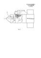
Сущность изобретения поясняется Фиг. 1, где изображен продольный разрез вращающегося реактивного снаряда.The invention is illustrated in FIG. 1, which shows a longitudinal section of a rotating missile.
Предлагаемый реактивный снаряд содержит головную часть 1, корпус 2, дно 3, заряд 4 с донной манжетой 5 и блок стабилизаторов 6 с косопоставленными аэродинамическими лопастями. Наружная поверхность донной манжеты в области дна выполнена в виде усеченного конуса, а на внутренней поверхности дна в области конического участка манжеты выполнена кольцевая коническая проточка, при этом длины конических участков манжеты L1 и кольцевой конической проточки дна L2 составляют не менее 0,1D, где D - калибр реактивного снаряда. Кольцевая коническая проточка выполнена с углом конуса α1, равным 0,8…1,2 угла конуса конического участка донной манжеты α2. Расстояние между коническим участком манжеты и кольцевой конической проточкой δ составляет (0,003…0,01)D.The proposed missile contains a
Предлагаемая ракета функционирует следующим образом.The proposed rocket operates as follows.
При подаче электрического импульса на ракету происходит зажигание заряда 4, продукты сгорания которого истекают из реактивного снаряда, создавая реактивную тягу, вследствие чего реактивный снаряд сходит с направляющей и движется по траектории. За счет блока стабилизаторов 6 с косопоставленными аэродинамическими стабилизаторами осуществляется вращение ракеты на траектории, при этом консольный участок заряда 4 за счет центробежных сил деформируется в направлении дна 3. За счет предлагаемого расстояния между коническими участками наружной поверхности манжеты 5 и внутренней поверхности дна 3 и предлагаемого соотношения углов конусов и длин указанных участков обеспечивается контакт указанных участков, исключая тем самым возможность недопустимых деформаций заряда 4.When an electric pulse is applied to the rocket, a charge 4 is ignited, the combustion products of which flow out of the rocket, creating a jet propulsion, as a result of which the rocket rolls off the guide and moves along the trajectory. Due to the block of
Выполнение реактивного снаряда в соответствии с предлагаемым изобретением позволило повысить надежность функционирования реактивного снаряда.The implementation of the rocket in accordance with the invention has improved the reliability of the functioning of the rocket.
Изобретение может быть использовано при разработке реактивных снарядов, в том числе для реактивных снарядов систем залпового огня.The invention can be used in the development of rockets, including rockets for multiple launch rocket systems.
Указанный положительный эффект подтвержден испытаниями опытных образцов реактивных снарядов, выполненных в соответствии с изобретением.The indicated positive effect is confirmed by tests of prototypes of rockets made in accordance with the invention.
В настоящее время разработана конструкторская документация, проведены государственные испытания, намечено серийное производство.Currently, design documentation has been developed, state tests have been carried out, and mass production is scheduled.
Claims (1)
Priority Applications (1)
| Application Number | Priority Date | Filing Date | Title |
|---|---|---|---|
| RU2016130816A RU2623373C1 (en) | 2016-07-26 | 2016-07-26 | Missile |
Applications Claiming Priority (1)
| Application Number | Priority Date | Filing Date | Title |
|---|---|---|---|
| RU2016130816A RU2623373C1 (en) | 2016-07-26 | 2016-07-26 | Missile |
Publications (1)
| Publication Number | Publication Date |
|---|---|
| RU2623373C1 true RU2623373C1 (en) | 2017-06-26 |
Family
ID=59241503
Family Applications (1)
| Application Number | Title | Priority Date | Filing Date |
|---|---|---|---|
| RU2016130816A RU2623373C1 (en) | 2016-07-26 | 2016-07-26 | Missile |
Country Status (1)
| Country | Link |
|---|---|
| RU (1) | RU2623373C1 (en) |
Cited By (1)
| Publication number | Priority date | Publication date | Assignee | Title |
|---|---|---|---|---|
| RU2814001C1 (en) * | 2023-06-02 | 2024-02-21 | Акционерное общество "Научно-производственное объединение "СПЛАВ" им. А.Н. Ганичева" | Rocket part of rocket projectile |
Citations (5)
| Publication number | Priority date | Publication date | Assignee | Title |
|---|---|---|---|---|
| US4588145A (en) * | 1983-08-15 | 1986-05-13 | General Dynamics Pomona Division | Missile tail fin assembly |
| RU94029576A (en) * | 1994-08-05 | 1996-06-20 | Конструкторское бюро приборостроения | Common-rocket projectile |
| RU2166178C1 (en) * | 2000-03-23 | 2001-04-27 | Государственное унитарное предприятие Брянский химический завод | Spin-stabilized supersonic missile |
| RU2182309C1 (en) * | 2001-08-08 | 2002-05-10 | Государственное унитарное предприятие Бийское производственное объединение "Сибприбормаш" | Tail unit of spin-stabilized missile |
| RU2328696C2 (en) * | 2006-09-14 | 2008-07-10 | Федеральное государственное унитарное предприятие "Производственное объединение "Алмаз" | Solid-fuel rotary jet shell charge cassette case |
-
2016
- 2016-07-26 RU RU2016130816A patent/RU2623373C1/en active
Patent Citations (5)
| Publication number | Priority date | Publication date | Assignee | Title |
|---|---|---|---|---|
| US4588145A (en) * | 1983-08-15 | 1986-05-13 | General Dynamics Pomona Division | Missile tail fin assembly |
| RU94029576A (en) * | 1994-08-05 | 1996-06-20 | Конструкторское бюро приборостроения | Common-rocket projectile |
| RU2166178C1 (en) * | 2000-03-23 | 2001-04-27 | Государственное унитарное предприятие Брянский химический завод | Spin-stabilized supersonic missile |
| RU2182309C1 (en) * | 2001-08-08 | 2002-05-10 | Государственное унитарное предприятие Бийское производственное объединение "Сибприбормаш" | Tail unit of spin-stabilized missile |
| RU2328696C2 (en) * | 2006-09-14 | 2008-07-10 | Федеральное государственное унитарное предприятие "Производственное объединение "Алмаз" | Solid-fuel rotary jet shell charge cassette case |
Non-Patent Citations (1)
| Title |
|---|
| МАКАРОВЕЦ Н.А. и др. Разделение неуправляемых снарядов систем залпового огня, Москва, Машиностроение, 2008, с. 417. * |
Cited By (2)
| Publication number | Priority date | Publication date | Assignee | Title |
|---|---|---|---|---|
| RU2814001C1 (en) * | 2023-06-02 | 2024-02-21 | Акционерное общество "Научно-производственное объединение "СПЛАВ" им. А.Н. Ганичева" | Rocket part of rocket projectile |
| RU2848251C1 (en) * | 2024-07-17 | 2025-10-16 | Акционерное общество "Научно-производственное объединение "СПЛАВ" им. А.Н. Ганичева" | Jet projectile launched from tubular guide |
Similar Documents
| Publication | Publication Date | Title |
|---|---|---|
| US3698321A (en) | Rocket assisted projectile | |
| US3442083A (en) | Adjustable variable thrust propulsion device | |
| US10184762B2 (en) | Base drag reduction fairing using shape memory materials | |
| US2715874A (en) | Projectile with a bourrelet retaining a segmented ring in a core-groove | |
| RU2623373C1 (en) | Missile | |
| RU2125175C1 (en) | Solid-propellant rocket engine | |
| CN101113882A (en) | Bomb body structure capable of reducing shock wave drag of bomb body and method thereof | |
| KR20210019189A (en) | Projectile containing ramjet engine | |
| US11248890B2 (en) | Enhanced ballistics and projectiles | |
| KR101609507B1 (en) | Range Extension Form Ramjet Propelled Shell | |
| US12332033B2 (en) | Munition with directional projection explosive | |
| RU2482431C1 (en) | Cartridge for small arms and artillery smoothbore systems | |
| RU2569989C1 (en) | Solid fuel rocket engine | |
| RU2809456C1 (en) | Cassette warhead | |
| RU2736456C1 (en) | Nozzle plug of rocket engine of solid fuel | |
| RU2798116C1 (en) | Missile part of a rotating rocket projectile launched from a smoothbore tubular guide | |
| RU2827063C1 (en) | Missile warhead housing | |
| RU2559657C1 (en) | Jet projectile rocket section | |
| RU2775451C1 (en) | Rocket part of a jet-propelled projectile | |
| RU2795013C1 (en) | Missile | |
| RU2790916C1 (en) | Dual-mode solid propellant rocket engine | |
| RU2447310C1 (en) | Solid-propellant rocket engine body | |
| RU2805438C1 (en) | Rocket launch block | |
| RU2847776C1 (en) | Universal ammunition casing with integrated striking elements | |
| RU2235281C2 (en) | Rocket missile |