RU2622371C2 - Electrical activity map provision system - Google Patents
Electrical activity map provision system Download PDFInfo
- Publication number
- RU2622371C2 RU2622371C2 RU2013142269A RU2013142269A RU2622371C2 RU 2622371 C2 RU2622371 C2 RU 2622371C2 RU 2013142269 A RU2013142269 A RU 2013142269A RU 2013142269 A RU2013142269 A RU 2013142269A RU 2622371 C2 RU2622371 C2 RU 2622371C2
- Authority
- RU
- Russia
- Prior art keywords
- heart
- projection images
- determining
- surface electrodes
- positions
- Prior art date
Links
Images
Classifications
-
- A—HUMAN NECESSITIES
- A61—MEDICAL OR VETERINARY SCIENCE; HYGIENE
- A61B—DIAGNOSIS; SURGERY; IDENTIFICATION
- A61B5/00—Measuring for diagnostic purposes; Identification of persons
- A61B5/24—Detecting, measuring or recording bioelectric or biomagnetic signals of the body or parts thereof
- A61B5/316—Modalities, i.e. specific diagnostic methods
- A61B5/318—Heart-related electrical modalities, e.g. electrocardiography [ECG]
-
- A—HUMAN NECESSITIES
- A61—MEDICAL OR VETERINARY SCIENCE; HYGIENE
- A61B—DIAGNOSIS; SURGERY; IDENTIFICATION
- A61B5/00—Measuring for diagnostic purposes; Identification of persons
- A61B5/06—Devices, other than using radiation, for detecting or locating foreign bodies ; determining position of probes within or on the body of the patient
- A61B5/065—Determining position of the probe employing exclusively positioning means located on or in the probe, e.g. using position sensors arranged on the probe
-
- A—HUMAN NECESSITIES
- A61—MEDICAL OR VETERINARY SCIENCE; HYGIENE
- A61B—DIAGNOSIS; SURGERY; IDENTIFICATION
- A61B5/00—Measuring for diagnostic purposes; Identification of persons
- A61B5/24—Detecting, measuring or recording bioelectric or biomagnetic signals of the body or parts thereof
- A61B5/25—Bioelectric electrodes therefor
- A61B5/279—Bioelectric electrodes therefor specially adapted for particular uses
- A61B5/28—Bioelectric electrodes therefor specially adapted for particular uses for electrocardiography [ECG]
- A61B5/282—Holders for multiple electrodes
-
- A—HUMAN NECESSITIES
- A61—MEDICAL OR VETERINARY SCIENCE; HYGIENE
- A61B—DIAGNOSIS; SURGERY; IDENTIFICATION
- A61B5/00—Measuring for diagnostic purposes; Identification of persons
- A61B5/68—Arrangements of detecting, measuring or recording means, e.g. sensors, in relation to patient
- A61B5/6801—Arrangements of detecting, measuring or recording means, e.g. sensors, in relation to patient specially adapted to be attached to or worn on the body surface
- A61B5/6802—Sensor mounted on worn items
- A61B5/6804—Garments; Clothes
- A61B5/6805—Vests
-
- A—HUMAN NECESSITIES
- A61—MEDICAL OR VETERINARY SCIENCE; HYGIENE
- A61B—DIAGNOSIS; SURGERY; IDENTIFICATION
- A61B5/00—Measuring for diagnostic purposes; Identification of persons
- A61B5/68—Arrangements of detecting, measuring or recording means, e.g. sensors, in relation to patient
- A61B5/6801—Arrangements of detecting, measuring or recording means, e.g. sensors, in relation to patient specially adapted to be attached to or worn on the body surface
- A61B5/684—Indicating the position of the sensor on the body
-
- A—HUMAN NECESSITIES
- A61—MEDICAL OR VETERINARY SCIENCE; HYGIENE
- A61B—DIAGNOSIS; SURGERY; IDENTIFICATION
- A61B6/00—Apparatus for radiation diagnosis, e.g. combined with radiation therapy equipment
-
- A—HUMAN NECESSITIES
- A61—MEDICAL OR VETERINARY SCIENCE; HYGIENE
- A61B—DIAGNOSIS; SURGERY; IDENTIFICATION
- A61B6/00—Apparatus for radiation diagnosis, e.g. combined with radiation therapy equipment
- A61B6/44—Constructional features of apparatus for radiation diagnosis
- A61B6/4429—Constructional features of apparatus for radiation diagnosis related to the mounting of source units and detector units
- A61B6/4435—Constructional features of apparatus for radiation diagnosis related to the mounting of source units and detector units the source unit and the detector unit being coupled by a rigid structure
- A61B6/4441—Constructional features of apparatus for radiation diagnosis related to the mounting of source units and detector units the source unit and the detector unit being coupled by a rigid structure the rigid structure being a C-arm or U-arm
-
- A—HUMAN NECESSITIES
- A61—MEDICAL OR VETERINARY SCIENCE; HYGIENE
- A61B—DIAGNOSIS; SURGERY; IDENTIFICATION
- A61B6/00—Apparatus for radiation diagnosis, e.g. combined with radiation therapy equipment
- A61B6/50—Clinical applications
- A61B6/503—Clinical applications involving diagnosis of heart
-
- A—HUMAN NECESSITIES
- A61—MEDICAL OR VETERINARY SCIENCE; HYGIENE
- A61B—DIAGNOSIS; SURGERY; IDENTIFICATION
- A61B8/00—Diagnosis using ultrasonic, sonic or infrasonic waves
- A61B8/08—Detecting organic movements or changes, e.g. tumours, cysts, swellings
- A61B8/0883—Detecting organic movements or changes, e.g. tumours, cysts, swellings for diagnosis of the heart
-
- A—HUMAN NECESSITIES
- A61—MEDICAL OR VETERINARY SCIENCE; HYGIENE
- A61B—DIAGNOSIS; SURGERY; IDENTIFICATION
- A61B8/00—Diagnosis using ultrasonic, sonic or infrasonic waves
- A61B8/12—Diagnosis using ultrasonic, sonic or infrasonic waves in body cavities or body tracts, e.g. by using catheters
-
- A—HUMAN NECESSITIES
- A61—MEDICAL OR VETERINARY SCIENCE; HYGIENE
- A61B—DIAGNOSIS; SURGERY; IDENTIFICATION
- A61B8/00—Diagnosis using ultrasonic, sonic or infrasonic waves
- A61B8/42—Details of probe positioning or probe attachment to the patient
- A61B8/4245—Details of probe positioning or probe attachment to the patient involving determining the position of the probe, e.g. with respect to an external reference frame or to the patient
- A61B8/4254—Details of probe positioning or probe attachment to the patient involving determining the position of the probe, e.g. with respect to an external reference frame or to the patient using sensors mounted on the probe
-
- A—HUMAN NECESSITIES
- A61—MEDICAL OR VETERINARY SCIENCE; HYGIENE
- A61B—DIAGNOSIS; SURGERY; IDENTIFICATION
- A61B2576/00—Medical imaging apparatus involving image processing or analysis
- A61B2576/02—Medical imaging apparatus involving image processing or analysis specially adapted for a particular organ or body part
- A61B2576/023—Medical imaging apparatus involving image processing or analysis specially adapted for a particular organ or body part for the heart
-
- G—PHYSICS
- G16—INFORMATION AND COMMUNICATION TECHNOLOGY [ICT] SPECIALLY ADAPTED FOR SPECIFIC APPLICATION FIELDS
- G16H—HEALTHCARE INFORMATICS, i.e. INFORMATION AND COMMUNICATION TECHNOLOGY [ICT] SPECIALLY ADAPTED FOR THE HANDLING OR PROCESSING OF MEDICAL OR HEALTHCARE DATA
- G16H30/00—ICT specially adapted for the handling or processing of medical images
- G16H30/40—ICT specially adapted for the handling or processing of medical images for processing medical images, e.g. editing
Abstract
Description
ОБЛАСТЬ ТЕХНИКИ, К КОТОРОЙ ОТНОСИТСЯ ИЗОБРЕТЕНИЕFIELD OF THE INVENTION
Настоящее изобретение относится к системе, способу и компьютерной программе для обеспечения карты электрической активности сердца живого существа с помощью электрических сигналов от сердца, получаемых множеством поверхностных электродов на внешней поверхности живого существа.The present invention relates to a system, method and computer program for providing a card of the electrical activity of the heart of a living creature with the help of electrical signals from the heart, obtained by many surface electrodes on the outer surface of a living creature.
УРОВЕНЬ ТЕХНИКИBACKGROUND
В патенте США №7471973 В2 раскрыта система, содержащая жилет с поверхностными электродами для измерения электрических потенциалов на внешней поверхности человека. Система кроме того содержит блок реконструкции для реконструкции эпикардиальных электрических потенциалов на основе: i) относительного расположения поверхности сердца и внешней поверхности человека; и ii) измеренных электрических потенциалов. Чтобы определить относительное положение поверхности сердца и внешней поверхности человека определяют первую проекционную матрицу на основе первого устройства формирования изображений и определяют вторую проекционную матрицу на основе второго устройства формирования изображений. По меньшей мере одно первое двумерное изображение сердца получают используя первое устройство формирования изображений, по меньшей мере одно второе двумерное изображение сердца получают, используя второе устройство формирования изображений, и определяют контур сердца в первом двумерном изображении и контур сердца во втором двумерном изображении. Трехмерные данные, связанные с поверхностью сердца, реконструируют на основе двух контуров, первой проекционной матрицы и второй проекционной матрицы, и поверхность сердца сопоставляют с внешней поверхностью человека. Относительное положение поверхности сердца и внешней поверхности человека окончательно определяют, используя метод граничных элементов.US Pat. No. 7471973 B2 discloses a system comprising a vest with surface electrodes for measuring electrical potentials on an external surface of a person. The system further comprises a reconstruction unit for reconstructing epicardial electrical potentials based on: i) the relative location of the surface of the heart and the external surface of the person; and ii) measured electrical potentials. To determine the relative position of the surface of the heart and the outer surface of a person, a first projection matrix is determined based on the first image forming apparatus and a second projection matrix is determined based on the second image forming apparatus. At least one first two-dimensional image of the heart is obtained using the first image forming apparatus, at least one second two-dimensional image of the heart is obtained using the second image forming apparatus, and the heart contour in the first two-dimensional image and the heart contour in the second two-dimensional image are determined. Three-dimensional data associated with the surface of the heart is reconstructed on the basis of two loops, a first projection matrix and a second projection matrix, and the surface of the heart is compared with the external surface of the person. The relative position of the surface of the heart and the external surface of a person is finally determined using the boundary element method.
Эта система имеет недостаток, состоящий в том, что качество определенного таким образом относительного расположения поверхности сердца и внешней поверхности человека может снизиться, что может привести к снижению точности определения эпикардиальных электрических потенциалов, которые определяют на основе этого относительного расположения.This system has the disadvantage that the quality of the relative arrangement of the surface of the heart and the external surface of the person so determined may decrease, which may lead to a decrease in the accuracy of determination of epicardial electric potentials, which are determined on the basis of this relative arrangement.
СУЩНОСТЬ ИЗОБРЕТЕНИЯSUMMARY OF THE INVENTION
Целью настоящего изобретения является создание системы, способа и компьютерной программы для обеспечения карты электрической активности сердца живого существа с помощью электрических сигналов от сердца, получаемых множеством поверхностных электродов на внешней поверхности живого существа, причем обеспеченная карта электрической активности имеет повышенное качество.The aim of the present invention is to provide a system, method and computer program for providing a card of electrical activity of the heart of a living creature with the help of electrical signals from the heart, obtained by many surface electrodes on the outer surface of a living creature, and the provided map of electrical activity is of high quality.
Согласно первому аспекту настоящего изобретения представлена система для обеспечения карты электрической активности сердца живого существа с помощью электрических сигналов от сердца, получаемых множеством поверхностных электродов на внешней поверхности живого существа, причем система содержит:According to a first aspect of the present invention, there is provided a system for providing a card of electrical activity of the heart of a living creature using electrical signals from the heart received by a plurality of surface electrodes on the outer surface of the living creature, the system comprising:
блок обеспечения проекционных изображений для обеспечения проекционных изображений сердца и множества поверхностных электродов в разных направлениях,a projection image providing unit for providing projection images of the heart and the plurality of surface electrodes in different directions,
блок определения положений поверхностных электродов для определения положений множества поверхностных электродов на основе обеспеченных проекционных изображений,a surface electrode position determining unit for determining positions of a plurality of surface electrodes based on provided projection images,
блок определения положения структуры сердца для определения положения структуры сердца живого существа на основе обеспеченных проекционных изображений, причем блок определения положения структуры сердца выполнен с возможностью адаптации анатомической модели сердца, включающую в себя структуру сердца, к обеспеченным проекционным изображениям сердца, чтобы определить положение структуры сердца,a unit for determining the position of the heart structure for determining the position of the heart structure of a living creature based on the provided projection images, the unit for determining the position of the heart structure is adapted to adapt the anatomical model of the heart, including the structure of the heart, to the provided projection images of the heart to determine the position of the heart structure,
блок определения карты электрической активности для определения карты электрической активности у структуры сердца на основе электрических сигналов, измеренных на внешней поверхности живого существа, определенных положений множества поверхностных электродов и определенного положения структуры сердца.an electric activity map determination unit for determining an electrical activity map of a heart structure based on electrical signals measured on the external surface of a living creature, certain positions of a plurality of surface electrodes and a specific position of the heart structure.
Поскольку положение структуры сердца живого существа определяют путем адаптации анатомической модели сердца, включающей в себя структуру сердца, к обеспеченным проекционным изображениям сердца, положение структуры сердца можно определить с относительно высокой точностью, просто используя несколько проекционных изображений. Кроме того, поскольку положение структуры сердца можно определить с высокой точностью, карту электрической активности на структуре сердца, которую определяют на основе: а) электрических сигналов, измеренных на внешней поверхности живого существа, b) определенных положений множества электродов и с) определенного положения структуры сердца, также можно определить с повышенной точностью, что повышает качество определенной карты электрической активности.Since the position of the heart structure of a living creature is determined by adapting the anatomical model of the heart, which includes the structure of the heart, to the provided projection images of the heart, the position of the heart structure can be determined with relatively high accuracy, simply using several projection images. In addition, since the position of the heart structure can be determined with high accuracy, a map of electrical activity on the structure of the heart, which is determined on the basis of: a) electrical signals measured on the external surface of a living creature, b) specific positions of a plurality of electrodes and c) a specific position of the heart structure , can also be determined with increased accuracy, which improves the quality of a certain card of electrical activity.
Структурой сердца предпочтительно является эпикардиальная поверхность сердца. Таким образом, блок определения карты электрической активности предпочтительно выполнен с возможностью определения карты электрической активности на эпикардиальной поверхности сердца на основе электрических сигналов, измеренных на внешней поверхности живого существа, определенных положений множества электродов и определенного положения эпикардиальной поверхности сердца.The structure of the heart is preferably the epicardial surface of the heart. Thus, the electric activity map determination unit is preferably configured to determine the electrical activity map on the epicardial surface of the heart based on electrical signals measured on the external surface of the living creature, certain positions of the plurality of electrodes, and a specific position of the epicardial surface of the heart.
Если структура сердца является трехмерной, в частности, если структура сердца представляет собой трехмерную эпикардиальную поверхность, то положение структуры сердца предпочтительно определяет положение каждой точки структуры сердца, для которой необходимо определить карту электрической активности. Следовательно, если, например, блок определения положения структуры сердца определяет положение эпикардиальной поверхности, он определяет по меньшей мере положения тех точек на эпикардиальной поверхности, электрический потенциал которых следует определить для создания карты электрической активности.If the heart structure is three-dimensional, in particular, if the heart structure is a three-dimensional epicardial surface, then the position of the heart structure preferably determines the position of each point of the heart structure for which it is necessary to determine the map of electrical activity. Therefore, if, for example, the block for determining the position of the structure of the heart determines the position of the epicardial surface, it determines at least the positions of those points on the epicardial surface whose electric potential should be determined to create a map of electrical activity.
Множество поверхностных электродов можно рассматривать как элемент системы или можно рассматривать как отдельный элемент, и система адаптирована к использованию электрических сигналов поверхностных электродов для обеспечения электрической активности сердца.Many surface electrodes can be considered as an element of the system or can be considered as a separate element, and the system is adapted to use the electrical signals of the surface electrodes to ensure electrical activity of the heart.
Множество поверхностных электродов может быть встроено в жилет, который можно надеть на живое существо. Живым существом предпочтительно является человек, но им может быть также животное.Many surface electrodes can be integrated into a vest that can be worn on a living creature. The living entity is preferably a human being, but it can also be an animal.
Блок определения положений поверхностных электродов предпочтительно выполнен с возможностью определения трехмерных положений поверхностных электродов исходя их двух или более обеспеченных двумерных проекционных изображений, которые предпочтительно представляют собой двумерные рентгеновские проекционные изображения. Указанный блок можно адаптировать для обеспечения модельного распределения поверхностных электродов для адаптации модельного распределения к обеспеченным проекционным изображениям и определения положений множества поверхностных электродов исходя из адаптированного модельного распределения. Это позволяет определить положения поверхностных электродов с высокой точностью только на основе уже обеспеченных проекционных изображений.The surface electrode position determining unit is preferably configured to determine three-dimensional positions of surface electrodes based on two or more provided two-dimensional projection images, which are preferably two-dimensional X-ray projection images. The specified block can be adapted to provide a model distribution of surface electrodes to adapt the model distribution to the provided projection images and determine the positions of many surface electrodes based on the adapted model distribution. This allows you to determine the position of the surface electrodes with high accuracy only on the basis of already provided projection images.
Модель сердца предпочтительно является неспецифической моделью сердца. Неспецифическая модель сердца представляет собой анатомическую модель сердца, которая не привязана к конкретному живому существу, в частности, не привязана к конкретному человеку.The heart model is preferably a non-specific heart model. A non-specific model of the heart is an anatomical model of the heart that is not tied to a specific living being, in particular, is not tied to a specific person.
Блок определения положения структуры сердца предпочтительно выполнен с возможностью адаптации анатомической модели сердца, включающей в себя структуру сердца, к обеспеченным проекционным изображениям сердца путем выполнения по меньшей мере одной из процедур: процедуры преобразования, процедуры поворота и/или процедуры масштабирования. Таким образом, в одном варианте блок определения положения структуры сердца может быть адаптирован просто к позиционированию и, но не обязательно, к масштабированию неспецифической модели сердца, с тем чтобы она соответствовала обеспеченным проекционным изображениям без модификации формы модели сердца. Это позволяет очень быстро адаптировать анатомическую модель сердца к обеспеченным проекционным изображениям. В другом варианте возможна также модификация формы анатомической модели сердца, чтобы адаптировать анатомическую модель сердца к обеспеченным проекционным изображениям. Например, анатомическую модель сердца можно растянуть или сжать в конкретных направлениях для адаптации анатомической модели сердца к обеспеченным проекционным изображениям.The block for determining the position of the heart structure is preferably adapted to adapt the anatomical model of the heart, which includes the structure of the heart, to the provided projection images of the heart by performing at least one of the procedures: the conversion procedure, the rotation procedure, and / or the scaling procedure. Thus, in one embodiment, the block for determining the position of the heart structure can be adapted simply to positioning and, but not necessarily, to scale the nonspecific model of the heart so that it matches the provided projection images without modifying the shape of the heart model. This allows you to very quickly adapt the anatomical model of the heart to the provided projection images. In another embodiment, it is also possible to modify the shape of the anatomical model of the heart in order to adapt the anatomical model of the heart to the provided projection images. For example, the anatomical model of the heart can be stretched or compressed in specific directions to adapt the anatomical model of the heart to the provided projection images.
Кроме того, предпочтительно, чтобы блок обеспечения проекционных изображений представлял собой рентгеновскую систему с рамой C-типа. Рентгеновская система с рамой С-типа позволяет получать относительно простым путем проекционные изображения в разных направлениях. Рентгеновскую систему с рамой С-типа можно адаптировать для выполнения перемещения вдоль одной оси рамы С-типа или перемещения по двум осям рамы С-типа. Кроме того, рентгеновская система с рамой С-типа может представлять собой одноплоскостную проекционную систему или двухплоскостную проекционную систему. Двухплоскостная проекционная система дает возможность одновременно получить проекционное изображение в разных направлениях. Одноплоскостная проекционная система может поворачиваться относительно живого существа, чтобы получить проекционные изображения в разных направлениях.In addition, it is preferable that the projection image support unit is an X-ray system with a C-type frame. An X-ray system with a C-type frame makes it possible to obtain projection images in different directions in a relatively simple way. An X-ray system with a C-type frame can be adapted to move along one axis of the C-type frame or move along two axes of the C-type frame. In addition, the X-ray system with a C-type frame may be a single-plane projection system or a two-plane projection system. A two-plane projection system makes it possible to simultaneously obtain a projection image in different directions. A single-plane projection system can rotate relative to a living creature to obtain projection images in different directions.
В одном варианте блок обеспечения проекционных изображений представляет собой систему с рамой С-типа для обеспечения нескольких двумерных рентгеновских проекционных изображений, блок определения положений поверхностных электродов адаптирован для определения положений множества поверхностных электродов путем выполнения моделирования трехмерных положений на основе нескольких двумерных рентгеновских проекционных изображений, блок определения положения структуры сердца выполнен с возможностью согласования обобщенной трехмерной не привязанной к пациенту модели сердца с контуром сердца в выбранных двумерных рентгеновских проекционных изображениях из нескольких двумерных рентгеновских проекционных изображений, а блок определения карты электрической активности адаптирован для определения карты электрической активности путем выполнения электрокардиографического картирования на поверхности согласованной обобщенной трехмерной модели сердца, что предпочтительно обеспечивает картину «одноударной» эпикардиальной активации в режиме реального времени или подобном режиме с диагностическими возможностями миокарда, далеко опережающими современные системы ECG.In one embodiment, the projection image support unit is a C-type frame system for providing several two-dimensional X-ray projection images, the surface electrode positioning unit is adapted to determine the positions of the plurality of surface electrodes by performing three-dimensional position modeling based on several two-dimensional X-ray projection images, the determination unit the position of the structure of the heart is made with the possibility of matching generalized three-dimensional a non-patient heart model with a heart outline in selected two-dimensional X-ray projection images from several two-dimensional X-ray projection images, and the electric activity map determination unit is adapted to determine the electrical activity map by performing electrocardiographic mapping on the surface of an agreed generalized three-dimensional heart model, which preferably provides a picture "Single-stroke" epicardial activation in real time or under Another mode with diagnostic capabilities of the myocardium, far ahead of modern ECG systems.
Блок обеспечения проекционных изображений также может представлять собой запоминающее устройство, в котором уже хранятся проекционные изображения, и из которого эти проекционные изображения можно извлекать с той же целью. Блок обеспечения проекционных изображений также может представлять собой приемный блок для приема проекционных изображений через проводное или беспроводное соединение для передачи данных от блока получения проекционных изображений, такого как рентгеновская система с рамой С-типа.The projection image support unit may also be a storage device in which projection images are already stored, and from which these projection images can be extracted for the same purpose. The projection image support unit may also be a receiving unit for receiving projection images via a wired or wireless connection for transmitting data from the projection image acquisition unit, such as an X-ray system with a C-type frame.
Согласно еще одному аспекту настоящего изобретения представлен способ для обеспечения карты электрической активности сердца живого существа с помощью электрических сигналов от сердца, получаемых множеством поверхностных электродов на внешней поверхности живого существа, причем способ включает:According to another aspect of the present invention, there is provided a method for providing a card of electrical activity of the heart of a living creature using electrical signals from the heart received by a plurality of surface electrodes on the outer surface of the living creature, the method comprising:
обеспечение проекционных изображений сердца и множества поверхностных электродов в разных направлениях блоком обеспечения проекционных изображенийproviding projection images of the heart and a plurality of surface electrodes in different directions with a block for providing projection images
определение положений множества поверхностных электродов на основе обеспеченных проекционных изображений блоком определения положений поверхностных электродов,determining the positions of the plurality of surface electrodes based on the provided projection images by the position determining unit of the surface electrodes,
определение положения структуры сердца живого существа на основе обеспеченных проекционных изображений блоком определения положения структуры сердца, причем анатомическую модель сердца, включающую в себя структуру сердца, адаптируют к обеспеченным проекционным изображениям сердца, чтобы определить положение структуры сердца,determining the position of the heart structure of a living creature based on the provided projection images by the heart structure position determination unit, the anatomical model of the heart including the structure of the heart being adapted to the provided projection images of the heart in order to determine the position of the heart structure,
определение карты электрической активности у структуры сердца на основе электрических сигналов, измеренных на внешней поверхности живого существа, определенных положений множества электродов и положения структуры сердца, определенного блоком определения карты электрической активности.determining a card of electrical activity in the heart structure based on electrical signals measured on the external surface of a living creature, certain positions of the plurality of electrodes and the position of the heart structure determined by the electric activity card determination unit.
Согласно следующему аспекту настоящего изобретения представлена компьютерная программа для обеспечения карты электрической активности сердца живого существа с помощью электрических сигналов от сердца, получаемых множеством поверхностных электродов, скомпонованных на внешней поверхности живого существа, причем компьютерная программа содержит средство программного кода для инициирования выполнения системой, определенной в п. 1 формулы изобретения, этапов способа, определенных в п. 9 формулы изобретения, при выполнении указанной компьютерной программы на компьютере, управляющем указанной системой.According to a further aspect of the present invention, there is provided a computer program for providing a card of electrical activity of a living creature’s heart with electrical signals from a heart obtained by a plurality of surface electrodes arranged on the external surface of a living creature, the computer program comprising program code means for initiating execution of the system defined in .1 claims, steps of the method defined in paragraph 9 of the claims, when performing the specified com yuternoy program on the computer, the control of this system.
Следует понимать, что система по п. 1, способ по п. 9 и компьютерная программа по п. 10 имеют похожие и/или идентичные предпочтительные варианты их осуществления, в частности, как это определено в зависимых пунктах формулы изобретения.It should be understood that the system of claim 1, the method of claim 9, and the computer program of
Следует понимать, что предпочтительным вариантом осуществления изобретения также может быть любая комбинация зависимых пунктов с соответствующим независимым пунктом формулы изобретения.It should be understood that a preferred embodiment of the invention may also be any combination of dependent claims with the corresponding independent claim.
Эти и другие аспекты изобретения будут объяснены со ссылками на описанные здесь варианты осуществления изобретения.These and other aspects of the invention will be explained with reference to embodiments of the invention described herein.
КРАТКОЕ ОПИСАНИЕ ЧЕРТЕЖЕЙBRIEF DESCRIPTION OF THE DRAWINGS
НА НИЖЕСЛЕДУЮЩИХ ЧЕРТЕЖАХ:IN THE FOLLOWING DRAWINGS:
фиг. 1 – схематическое примерное представление варианта системы для обеспечения карты электрической активности сердца живого существа;FIG. 1 is a schematic illustration of a variant of a system for providing a card of electrical activity of the heart of a living creature;
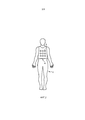
фиг. 2 – схематическое примерное представление варианта жилета, содержащего поверхностные электроды; иFIG. 2 is a schematic example representation of a variant of a vest containing surface electrodes; and
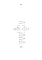
фиг. 3 – блок-схема, иллюстрирующая на примере вариант способа обеспечения карты электрической активности сердца живого существа.FIG. 3 is a flowchart illustrating, for example, an embodiment of a method for providing a card of electrical activity of the heart of a living creature.
ПОДРОБНОЕ ОПИСАНИЕ ВАРИАНТОВ ИЗОБРЕТЕНИЯDETAILED DESCRIPTION OF OPTIONS OF THE INVENTION
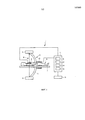
На фиг. 1 схематически в качестве примера показан один вариант системы для обеспечения карты электрической активности сердца живого существа с помощью электрических сигналов от сердца, получаемых множеством поверхностных электродов на внешней поверхности живого существа. В этом варианте живым существом является человек 6, лежащий на столе 7. На человека 6 надет жилет 8, схематически показанный в качестве примера на фиг. 2. Жилет 8 содержит множество поверхностных электродов 9, которые контактируют с внешней поверхностью грудной клетки человека 6, чтобы дать возможность поверхностным электродам 9 получать электрические сигналы, в частности, электрические потенциалы на внешней поверхности. Жилет 8 с множеством поверхностных электродов 9 электрически соединен с системой 17 определения, содержащей блок 13 определения карты электрической активности для пересылки электрических сигналов, измеренных множеством поверхностных электродов 9, в блок 13 определения карты электрической активности.In FIG. 1 schematically illustrates, as an example, one embodiment of a system for providing a card of electrical activity of a living creature’s heart with electrical signals from a heart received by a plurality of surface electrodes on the external surface of a living creature. In this embodiment, the living entity is
Следует заметить, что представленные здесь фигуры выполнены не в масштабе. Например, поверхностные электроды 9 в жилете 8, показанном на фиг. 2, имеют в действительности гораздо меньший диаметр по отношению к размерам человека 6. Кроме того, электроды 9 в жилете 8 показаны на фиг. 2 лишь схематически и только в качестве примера, то есть, они могут быть распределены по-другому в жилете 8. Жилет 8 предпочтительно содержит несколько сотен поверхностных электродов 9, покрывающих всю грудную клетку человека. Жилет 8 плотно прилепляют к коже грудной клетки связующим веществом. В качестве альтернативы или вдобавок к этому, жилет может содержать эластичные ленты для фиксации жилета на коже грудной клетки.It should be noted that the figures presented here are not made to scale. For example, surface electrodes 9 in the vest 8 shown in FIG. 2 actually have a much smaller diameter with respect to the size of the
Система 1 содержит блок 2 обеспечения проекционных изображений для обеспечения проекционных изображений сердца и множества поверхностных электродов 9 в разных направлениях. В этом варианте блок 2 обеспечения проекционных изображений представляет собой рентгеновскую систему с рамой С-типа. Рентгеновская система 2 с рамой С-типа содержит источник 3 рентгеновского излучения для излучения потока 16, проходящего через жилет 8 и сердце человека 6. Рентгеновский луч 16 предпочтительно представляет собой фактически конический рентгеновский луч, размеры которого таковы, что поверхностные электроды 9 и сердце человека 6 могут находиться в границах этого рентгеновского луча. После прохождения рентгеновского луча 16 через жилет 8 и сердце человека 6 он обнаруживается рентгеновским детектором 4. Рентгеновский детектор 4 содержит двумерную детекторную поверхность для создания двумерных проекционных изображений поверхностных электродов 9 и сердца человека 6. Рентгеновский источник 3 и рентгеновский детектор 4 смонтированы на раме 5 С-типа, которая может поворачиваться вокруг человека 6, так что можно получить проекционное изображение в разных направлениях. Управление рентгеновской системой 2 с рамой С-типа осуществляется блоком 10 управления, при этом созданные проекционные изображения подаются через блок 10 управления в систему 17 определения. В другом варианте проекционные изображения могут подаваться в систему 17 определения другим путем. Например, они могут передаваться в блок определения не через блок 10 управления, а непосредственно либо через другой блок.System 1 comprises a projection image support unit 2 for providing projection images of the heart and the plurality of surface electrodes 9 in different directions. In this embodiment, the projection image providing unit 2 is an X-ray system with a C-type frame. The X-ray system 2 with a C-type frame contains an
В данном варианте рентгеновская система 2 с рамой С-типа адаптирована для выполнения перемещения рамы С-типа относительно одной оси, то есть, для выполнения вращательного движения вокруг человека 6, которое определяется одной осью вращения. Однако в другом варианте рентгеновская система с рамой С-типа также адаптирована для выполнения перемещения рамы С-типа относительно двух осей, то есть, перемещения, которое можно определить как вращения вокруг двух осей.In this embodiment, the X-ray system 2 with a C-type frame is adapted to move the C-type frame relative to one axis, that is, to perform a rotational movement around the
В данном варианте рентгеновская система 2 с рамой С-типа является одноплоскостной проекционной системой, где одновременно можно получить только одно проекционное изображение. В другом варианте рентгеновская система с рамой С-типа может также представлять собой двухплоскостную проекционную систему, содержащую два рентгеновских источника и два рентгеновских детектора, скомпонованные таким образом, который обеспечивает возможность одновременного получения двух проекционных изображений в двух ортогональных направлениях проецирования.In this embodiment, the X-ray system 2 with a C-type frame is a single-plane projection system where only one projection image can be obtained at a time. In another embodiment, the X-ray system with a C-type frame may also be a two-plane projection system containing two X-ray sources and two X-ray detectors arranged in such a way that enables the simultaneous acquisition of two projection images in two orthogonal projection directions.
Система 17 определения содержит блок 11 определения положений поверхностных электродов для определения положений множества поверхностных электродов 9 на внешней поверхности человека 6 на основе обеспеченных проекционных изображений. В частности, блок 11 определения положений поверхностных электродов адаптирован для моделирования положений поверхностных электродов 9 исходя из проекционных изображений, чтобы определить положения множества поверхностных электродов 9. Например, можно обеспечить модельное распределение поверхностных электродов, и можно смоделировать создание обеспеченных проекционных изображений для создания смоделированных проекционных изображений путем прямого проецирования модельного распределения, где модельное распределение поверхностных электродов можно модифицировать таким образом, чтобы минимизировать отклонения между положениями спроецированных поверхностных электродов в обеспеченных действительных проекционных изображениях и в смоделированных проекционных изображениях. Результирующее модифицированное модельное распределение поверхностных электродов может затем обеспечить определение положений пространственных электродов. В другом варианте блоком определения положений поверхностных электродов могут быть использованы другие известные способы определения трехмерных положений объекта исходя из двух- и более- мерных проекционных изображений для определения положений множества поверхностных электродов на внешней поверхности человека на основе обеспеченных проекционных изображений.The
Перед определением положений множества поверхностных электродов на внешней поверхности человека на основе обеспеченных проекционных изображений можно увеличить контрастность спроецированных поверхностных электродов в обеспеченных проекционных изображениях путем выполнения процедуры повышения контрастности. Например, можно усреднить несколько проекционных изображений, которые были получены при одинаковом относительном расположении и без промежуточного перемещения человека, чтобы улучшить видимость поверхностных электродов в проекционных изображениях. Если человек переместился между получением двух проекционных изображений, подлежащих усреднению, то для фиксации этих двух изображений перед их усреднением можно использовать опорные маркеры, видимые на обоих изображениях.Before determining the positions of the plurality of surface electrodes on the outer surface of a person based on the provided projection images, it is possible to increase the contrast of the projected surface electrodes in the provided projection images by performing a contrast enhancement procedure. For example, it is possible to average several projection images that were obtained with the same relative position and without intermediate human movement in order to improve the visibility of surface electrodes in projection images. If a person has moved between obtaining two projection images to be averaged, then to fix these two images before averaging, you can use the reference markers visible on both images.
Система 17 определения кроме того содержит блок 12 определения положения структуры сердца для определения положения структуры сердца человека на основе обеспеченных проекционных изображений, где блок 12 определения положения структуры сердца адаптирован для адаптации в анатомической модели сердца, включающей в себя структуру сердца, к обеспеченным проекционным изображениям сердца, чтобы определить положение структуры сердца. В данном варианте структура сердца представляет собой эпикардиальную поверхность сердца, так что анатомическая модель сердца включает в себя по меньшей мере эпикардиальную поверхность сердца. Анатомическая модель сердца предпочтительно является моделью сердца, не привязанной к человеку. Таким образом, анатомическая модель сердца предпочтительно представляет собой обобщенную анатомическую модель сердца, которую можно получить, например, путем сегментации сердца во множестве медицинских изображений множества людей, создавая тем самым множество сегментированных сердец, и путем усреднения этого множества сегментированных сердец.The
Блок 12 определения положения структуры сердца предпочтительно адаптирован для преобразования, поворота и масштабирования модели сердца, так чтобы преобразованная модель сердца соответствовала обеспеченным проекционным изображениям. Блок 12 определения положения структуры сердца также может быть адаптирован для дополнительной деформации модели сердца, то есть, для модификации формы модели сердца, чтобы адаптировать модель сердца к обеспеченным проекционным изображениям. Например, модель сердца можно будет растянуть или сжать в определенных направлениях, для адаптации модели сердца к обеспеченным проекционным изображениям.The heart structure position determining unit 12 is preferably adapted to transform, rotate, and scale the heart model so that the transformed heart model matches the provided projection images. The heart structure position determination unit 12 can also be adapted to further deform the heart model, that is, to modify the shape of the heart model to adapt the heart model to the provided projection images. For example, a heart model can be stretched or compressed in certain directions to adapt the heart model to the provided projection images.
В частности, блок 12 определения положения структуры сердца может быть адаптирован для создания смоделированных проекционных изображений, которые соответствуют обеспеченным проекционным изображениям, путем имитации проекций посредством преобразованной модели сердца при относительном расположении, используемым для получения обеспеченных в действительности проекционных изображений. Затем модель сердца можно преобразовать таким образом, чтобы по меньшей мере минимизировать отклонения эпикардиальной поверхности между обеспеченными проекционными изображениями и смоделированными проекционными изображениями.In particular, the heart structure position determination unit 12 can be adapted to create simulated projection images that correspond to the provided projection images by simulating projections by means of a transformed model of the heart at a relative position used to obtain the actual projection images. Then, the heart model can be transformed so as to at least minimize deviations of the epicardial surface between the provided projection images and the simulated projection images.
Проекционные изображения, которые используют для определения положения структуры сердца, в частности, положения эпикардиальной поверхности, могут быть все обеспеченными проекционными изображениями или только отобранной частью обеспеченных проекционных изображений. Отобранная часть обеспеченных проекционных изображений можете включать в себя, левое переднее наклонное проекционное изображение и правое переднее наклонное проекционное изображение. Однако для определения положения структуры сердца, в частности положения эпикардиальной поверхности можно также использовать другие проекционные изображения.Projection images that are used to determine the position of the heart structure, in particular the position of the epicardial surface, can all be provided with projection images or only a selected portion of the provided projection images. A selected portion of the provided projection images may include a left front oblique projection image and a right front oblique projection image. However, other projection images can also be used to determine the position of the heart structure, in particular the position of the epicardial surface.
Система определения кроме того содержит блок 13 определения карты электрической активности для определения карты электрической активности у структуры сердца, то есть, в данном варианте на эпикардиаьной поверхности на основе электрических сигналов, измеренных на внешней поверхности человека 6, определенных положений множества поверхностных электродов 9 и определенного положения структуры сердца. Для определения карты электрической активности можно использовать хорошо известные способы, такие как способы, раскрытые в работе Ramanathan и др. «Electrocardiographic Imaging (ECGI): A Noninvasive Imaging Modality for Cardiac Electrophysiology and Arrhythmia», Nature Medicine 10, 422-428 (2004), или раскрытые в патенте США US№7471971, которые включены сюда по ссылке. Кроме того, для определения карты электрической активности у структуры сердца можно использовать известные продукты компаний CardioInsight Technologies и Amycard, то есть, в этом варианте на эпикардиальной поверхности на основе электрических сигналов, измеренных на внешней поверхности человека, определенных положений множества электродов и определенном положении структуры сердца.The determination system further comprises an electric activity
Система 17 определения кроме того содержит блок 14 анализа для анализа карты электрической активности с целью определения электрофизиологических механизмов конкретных сердечных аритмий. Кроме того, дополнительно или в качестве альтернативы, блок 14 анализа можно адаптировать для анализа картины электрической активности у пациентов с параличом сердца, который раскрыт в статьях P.S. Cuculich и др. "Noninvasive Characterization of Epicardial Activation in Humans with Diverse Atrial Fibrillation Patterns", Circulation 122, 1364-1372 (2010), Y. Wang и др. "Electrocardiographic Imaging of Ventricular Bigeminy in a Human Subject", Circulation Arrhythmia and Electrophysiology 1, 74-75 (2008) и P. Jia и др. "Electrocardiographic Imaging of Cardiac Resynchronization Therapy in Heart Failure: Observations of Variable Electrophysiological Responses", Heart Rhythm Journal 3, 296-310 (2006), содержание которых включено сюда по ссылке.The
В частности, блок анализа можно адаптировать для выполнения по меньшей мере одного из следующих видов анализа на основе карты электрической активности: определение анатомического положения эктопических очагов, определение анатомического положения вентрикулярных циркуляций возбуждения, различение циркуляции возбуждения и фокальной вентрикулярной тахикардии и оценка их местоположений, оценка восстановления проводимости легочных вен и локализация легочных вен, и оценка эффектов от антиаритмических препаратов.In particular, the analysis unit can be adapted to perform at least one of the following types of analysis based on an electrical activity map: determining the anatomical position of ectopic foci, determining the anatomical position of ventricular excitation circulations, distinguishing between excitation circulation and focal ventricular tachycardia and assessing their locations, assessing recovery conduction of pulmonary veins and localization of pulmonary veins, and assessment of the effects of antiarrhythmic drugs.
Карта электрической активности сердца и, но не обязательно, результаты анализа, например, определенные анатомические положения эктопических очагов и вентрикулярных циркуляций возбуждения могут быть показаны в блоке 15 отображения.A map of the electrical activity of the heart and, but not necessarily, the results of the analysis, for example, certain anatomical positions of ectopic foci and ventricular circulation of excitation, can be shown in the
Далее со ссылкой на блок-схему, показанную на фиг. 3, в качестве примера описывается вариант способа обеспечения карты электрической активности сердца живого существа с помощью электрических сигналов от сердца, полученных множеством поверхностных электродов на внешней поверхности живого существа.Next, with reference to the block diagram shown in FIG. 3, an example is described of a method for providing a card of electrical activity of the heart of a living creature using electrical signals from the heart received by a plurality of surface electrodes on the outer surface of the living creature.
На этапе 101 блоком обеспечения проекционных изображений обеспечиваются проекционные изображения сердца и множества поверхностных электродов в разных направлениях. Например, для получения проекционных изображений сердца и множества поверхностных электродов в разных направлениях используют рентгеновскую систему с рамой С-типа. На этапе 102 определяют положения множества поверхностных электродов на основе проекционных изображений, обеспеченных блоком определения положения поверхностных электродов. В частности, положения поверхностных электродов моделируют исходя из проекционных изображений, чтобы определить положения множества поверхностных электродов. На этапе 103 определяют положение структуры сердца живого существа на основе проекционных изображений, обеспеченных блоком определения положения структуры сердца, причем анатомическая модель сердца, включающая в себя структуру сердца, адаптирована к обеспеченным проекционным изображениям сердца, чтобы определить структуру сердца. В этом варианте структурой сердца является эпикардиальная поверхность, так что положение эпикардиальной поверхности определяют путем адаптации анатомической структуры сердца, включающей в себя эпикардиальную поверхность к обеспеченным проекционным изображениям сердца. Этап 102 и 103 могут выполняться в произвольном порядке, то есть, их можно выполнять последовательно или одновременно.At
На этапе 104 блок определения карты электрической активности определяет карту электрической активности у структуры сердца, то есть, в этом варианте, на эпикардиальной поверхности на основе электрических сигналов, измеренных на внешней поверхности человека, положений множества поверхностных электродов, определенных на этапе 102, и положения структуры сердца, определенного на этапе 103. На этапе 105 блок анализа анализирует карту электрической активности чтобы определить, например, анатомические позиции эктопических очагов и/или вентрикулярных циркуляций возбуждения. На этапе 106 карта электрической активности, а также, но не обязательно, результаты анализа, такие как анатомические положения эктопических очагов и/или вентрикулярных циркуляций возбуждения показываются в блоке отображения.In
В варианте способа обеспечения карты электрической активности сердца, описанном выше со ссылками на фиг. 3, предполагается, что электрические сигналы на внешней поверхности человека были уже измерены и поданы в блок определения карты электрической активности, чтобы дать возможность блоку определения карты электрической активности определить карту электрической активности. В другом варианте измерение электрических сигналов на внешней поверхности человека также может быть частью способа обеспечения карты электрической активности, где в этом случае соответствующий этап измерения электрических сигналов выполняется перед этапом 104.In an embodiment of the method for providing a card of electrical activity of the heart described above with reference to FIG. 3, it is assumed that the electrical signals on the outer surface of the person have already been measured and supplied to the electric activity map determination unit to enable the electric activity map determination unit to determine the electrical activity map. In another embodiment, the measurement of electrical signals on the external surface of a person may also be part of a method of providing a map of electrical activity, where in this case the corresponding step of measuring electrical signals is performed before
Электрокардиографическое картирование (ECM) – это способ, в котором для вычисления активности эпикардиальной поверхности сердца используют сигналы с поверхности тела, то есть, электрические сигналы, такие как электрические потенциалы, измеряемые на внешней поверхности человека, которые измеряются множеством электродов, покрывающих всю грудную клетку человека. Указанные электроды являются поверхностными электродами, то есть, электродами, измеряющими электрические сигналы на поверхности человека, причем эти электроды находятся в жилете, который плотно прилепляют к коже грудной клетки с помощью связующего вещества. Поскольку положение эпикардиальной поверхности сердца и положения поверхностных электродов были определены ранее, трехмерные пространственные соотношения между эпикардиальной поверхностью сердца и поверхностными электродами являются известными. Это позволяет блоку определения карты электрической активности вычислить точную картину «одноударной» электрической активации на эпикардиальной поверхности сердца, представляющую карту электрической активности. Следовательно, эта система, описанная выше со ссылками на фиг. 1, может обеспечить неинвазивный способ быстрой оценки (то есть, в пределах нескольких секунд в реальном времени) электрической активации сердца. Это электрокардиографическое картирование может выполняться, например, во время электрофизиологической процедуры или во время интервенционных кардиологических процедур в соответствующей лаборатории. Однако электрокардиографическое картирование также может выполняться для прединтервенционных и постинтервенционных дополнительных диагностических процедур. В частности, электрокардиографическое картирование можно использовать для оценки эффектов от противоаритмических лекарств в некоторых точках во время курсового лечения, а также можно использовать для выполнения электрокардиографического анализа с высоким разрешением.Electrocardiographic mapping (ECM) is a method in which signals from the surface of the body are used to calculate the activity of the epicardial surface of the heart, that is, electrical signals, such as electrical potentials measured on the external surface of a person, which are measured by a plurality of electrodes covering the entire human chest . These electrodes are surface electrodes, that is, electrodes that measure electrical signals on the surface of a person, and these electrodes are in a vest that adheres tightly to the skin of the chest with a binder. Since the position of the epicardial surface of the heart and the position of the surface electrodes have been previously determined, three-dimensional spatial relationships between the epicardial surface of the heart and surface electrodes are known. This allows the electric activity map determination unit to calculate the exact picture of the “single shock” electrical activation on the epicardial surface of the heart, representing the electrical activity map. Therefore, this system described above with reference to FIG. 1 can provide a non-invasive way to quickly evaluate (that is, within a few seconds in real time) the electrical activation of the heart. This electrocardiographic mapping may be performed, for example, during an electrophysiological procedure or during interventional cardiological procedures in an appropriate laboratory. However, electrocardiographic mapping can also be performed for pre-interventional and post-interventional additional diagnostic procedures. In particular, electrocardiographic mapping can be used to evaluate the effects of anti-arrhythmic drugs at some points during the course of treatment, and can also be used to perform high resolution electrocardiographic analysis.
Блок определения положений поверхностных электродов предпочтительно адаптирован для выполнения трехмерного моделирования положений электродов исходя из нескольких двумерных рентгеновских проекций, создаваемые рентгеновской системой с рамой C-типа. Рентгеновской системой с рамой С-типа является, например, система Philips Allura Xper FD10 или FD20 или мобильная рентгеновская система с рамой С-типа, такая как системы Philips Veradius или BV. Рентгеновская система с рамой С-типа может быть адаптирована для выполнения двухплоскостного формирования изображений для одновременного создания двух проекционных изображений, или может быть адаптирована для получения двух или более проекционных изображений путем выполнения одноплоскостного формирования изображений рамы С-типа, причем блок определения положений поверхностных электродов может быть адаптирован для определения трехмерных положений всех поверхностных электродов посредством трехмерного моделировании из двух или более отдельных проекционных изображений, предпочтительно двумерных флюороскопических или экспонированных рентгеновских изображений. Рентгеновская система с рамой С-типа также может быть адаптирована для выполнения перемещения рамы С-типа по двум осям, обеспечивая перемещение рентгеновского источника и рентгеновского детектора по оптимальной траектории, чтобы получить все электроды в выбранных рентгеновских кадрах для трехмерного моделирования положения электродов.The surface electrode position determining unit is preferably adapted to perform three-dimensional modeling of the electrode positions based on several two-dimensional X-ray projections created by an X-ray system with a C-type frame. An X-ray system with a C-type frame is, for example, a Philips Allura Xper FD10 or FD20 system or a mobile X-ray system with a C-type frame, such as Philips Veradius or BV systems. An X-ray system with a C-type frame can be adapted to perform two-plane imaging to simultaneously create two projection images, or can be adapted to obtain two or more projection images by performing a single-plane imaging of a C-type frame, and the surface electrode position determination unit may be adapted to determine the three-dimensional positions of all surface electrodes through three-dimensional modeling of two or Lee separate image projection, preferably two-dimensional fluoroscopic X-ray or exposed images. An X-ray system with a C-type frame can also be adapted to move the C-type frame along two axes, allowing the X-ray source and X-ray detector to move along the optimal path to obtain all the electrodes in the selected X-ray frames for three-dimensional modeling of the position of the electrodes.
Система, описанная выше со ссылками на фиг. 1, может работать в режиме определения карты электрической активности, для которого требуется только краткий протокол сбора данных для рамы С-типа без каких-либо требований к стерильности, то есть, человек не должен раздеваться и т.д. при очень ограниченной дозе рентгеновского излучения.The system described above with reference to FIG. 1, it can work in the mode of determining the map of electrical activity, which requires only a brief data collection protocol for the C-type frame without any sterility requirements, that is, a person should not undress, etc. with a very limited dose of x-rays.
Блок определения положения структуры сердца предпочтительно согласовывает обобщенную трехмерную модель сердца, не привязанную к конкретному пациенту, с контуром сердца, изображенным под различными проекционными углами, выбранными из двумерных рентгеновских сеансов, используемых для моделирования трехмерных положений электродов. Блок определения карты электрической активности предпочтительно выполняет электрокардиографическое картирование на поверхности обобщенной модели сердца, чтобы обеспечить аппроксимированную картину «одноударной» эпикардиальной активации, имеющую диагностические возможности миокарда, далеко опережающие известные электрокардиографические системы, которые предоставляют лишь очень грубую информацию об активации миокарда.The heart structure position determining unit preferably matches a generalized three-dimensional model of the heart that is not tied to a particular patient with a heart outline depicted at various projection angles selected from two-dimensional X-ray sessions used to model the three-dimensional positions of the electrodes. The electric activity map determination unit preferably performs electrocardiographic mapping on the surface of a generalized model of the heart to provide an approximated picture of a “one-hit” epicardial activation having myocardial diagnostic capabilities, far ahead of known electrocardiographic systems that provide only very rough information about myocardial activation.
Система, описанная выше со ссылками на фиг. 1, обеспечивает электрокардиографическое картирование на основе трехмерного моделирования положений электродов в жилете посредством быстрого формирования изображений с использованием рамы С-типа в сочетании с согласованием обобщенной трехмерной модели сердца. Таким образом, система предоставляет электрокардиографический диагностический инструмент, который можно использовать, например, для получения прединтервенционной и постинтервенционной информации, которую невозможно получить с помощью известных электрокардиографических систем. Например, можно получить такую информацию, как достаточно точные положения эктопических очагов, достаточно точные положения вентрикулярных циркуляций возбуждения, информацию, которая позволяет различить циркуляционную и фокальную вентрикулярную тахикардию и их локализовать, информацию о восстановлении проводимости легочных вен и локализации виновных легочных вен, чтобы по меньшей мере иметь возможность отличить левые легочные вены от правых и, информацию об эффектах противоаритмических лекарств в частности, о всяческих изменениях при использовании антиаритмических лекарств.The system described above with reference to FIG. 1, provides electrocardiographic mapping based on three-dimensional modeling of the positions of the electrodes in a vest by quickly forming images using a C-type frame in combination with matching a generalized three-dimensional model of the heart. Thus, the system provides an electrocardiographic diagnostic tool that can be used, for example, to obtain pre-interventional and post-interventional information that cannot be obtained using known electrocardiographic systems. For example, you can obtain information such as fairly accurate positions of ectopic foci, fairly accurate positions of ventricular excitation circulations, information that allows you to distinguish between circulation and focal ventricular tachycardia and localize them, information on the restoration of pulmonary vein conduction and localization of guilty pulmonary veins, so that at least least able to distinguish between left pulmonary veins and right veins, and information on the effects of antiarrhythmic drugs, in particular, on any changes when using antiarrhythmic drugs.
Специалисты в данной области техники, изучив чертежи, описание и прилагаемую формулу изобретения, смогут оценить и опробовать другие версии раскрытых здесь вариантов при практической реализации заявленного изобретения.Specialists in the art, having studied the drawings, description and the attached claims, will be able to evaluate and test other versions of the options disclosed here in the practical implementation of the claimed invention.
В формуле изобретения термин «содержащий» не исключает наличия других элементов или этапов, а неопределенный артикль «а» или «an» не исключает наличия множества объектов.In the claims, the term “comprising” does not exclude the presence of other elements or steps, and the indefinite article “a” or “an” does not exclude the presence of a plurality of objects.
Один блок или устройство может выполнять функции нескольких объектов, упомянутых в формуле изобретения. Тот факт, что некоторые показатели упоминаются во взаимно различных зависимых пунктах формулы изобретения, не указывает на то, что нельзя с успехом использовать комбинацию этих показателей.A single unit or device can fulfill the functions of several objects mentioned in the claims. The fact that some indicators are mentioned in mutually different dependent claims does not indicate that a combination of these indicators cannot be successfully used.
Операции определения, такие как определение положений поверхностных электродов, определение положения структуры сердца, определение карты электрической активности и анализ карты электрической активности, выполняемый одним или несколькими блоками или устройствами, могут выполняться любым другим количеством блоков или устройств. Например, этапы 102-105 могут выполняться одним блоком или любым другим количеством разных блоков. Определения и/или анализ карты электрической активности и/или управление системой для обеспечения карты электрической активности согласно указанному способу обеспечения карты электрической активности, могут быть реализованы в виде средства программного кода компьютерной программы и/или в виде специализированного аппаратного обеспечения.Detection operations, such as determining the positions of surface electrodes, determining the position of the heart structure, determining the electrical activity map, and analyzing the electrical activity map, performed by one or more blocks or devices, can be performed by any other number of blocks or devices. For example, steps 102-105 may be performed by one block or any other number of different blocks. The definitions and / or analysis of the electrical activity map and / or the management of the system to provide the electrical activity map according to the specified method of providing the electrical activity map can be implemented in the form of a computer program code tool and / or in the form of specialized hardware.
Компьютерная программа может храниться в и/или может быть распространяться на подходящем носителе, таком как оптический носитель или твердотельный носитель, поставляемый вместе с другим аппаратным обеспечением или в виде его части, а также может быть предоставлена в других видах, например, через Интернет или другие проводные или беспроводные телекоммуникационные системы.The computer program may be stored in and / or may be distributed on a suitable medium, such as optical media or solid state media, supplied with or in part of other hardware, and may also be provided in other forms, for example, via the Internet or other wired or wireless telecommunication systems.
Любые ссылочные позиции в пунктах формулы изобретения не следует трактовать как ограничение ее объема.Any reference position in the claims should not be construed as limiting its scope.
Изобретение относится к системе для обеспечения карты электрической активности сердца с помощью электрических сигналов, получаемых от множества поверхностных электродов на внешней поверхности живого существа. Блок определения положения структуры сердца определяет положение структуры сердца, в частности, эпикардиальной поверхности, на основе обеспеченных проекционных изображений, причем анатомическая модель сердца адаптирована к проекционным изображениям. Блок определения карты электрической активности определяет карты электрической активности у структуры сердца на основе электрических сигналов, положений множества поверхностных электродов, также определенных из проекционных изображений, и определенного положения структуры сердца. Это позволяет определить карту электрической активности у структуры сердца с высокой точностью, например, без необходимости использования компьютеризированной рентгеновской томографической системы, при использовании которой живое существо получает относительно высокую дозу рентгеновского излучения.The invention relates to a system for providing a card of electrical activity of the heart with the help of electrical signals received from a plurality of surface electrodes on the external surface of a living being. The unit for determining the position of the heart structure determines the position of the heart structure, in particular, the epicardial surface, based on the provided projection images, and the anatomical model of the heart is adapted to the projection images. The electric activity map determination unit determines the electrical activity maps of the heart structure based on electrical signals, the positions of the plurality of surface electrodes also determined from the projection images, and the determined position of the heart structure. This allows you to determine the map of electrical activity in the heart structure with high accuracy, for example, without the need for a computerized x-ray tomography system, when using which a living creature receives a relatively high dose of x-ray radiation.
Claims (22)
Applications Claiming Priority (3)
| Application Number | Priority Date | Filing Date | Title |
|---|---|---|---|
| EP11154871 | 2011-02-17 | ||
| EP11154871.5 | 2011-02-17 | ||
| PCT/IB2012/050650 WO2012110940A1 (en) | 2011-02-17 | 2012-02-14 | System for providing an electrical activity map |
Publications (2)
| Publication Number | Publication Date |
|---|---|
| RU2013142269A RU2013142269A (en) | 2015-03-27 |
| RU2622371C2 true RU2622371C2 (en) | 2017-06-14 |
Family
ID=45774282
Family Applications (2)
| Application Number | Title | Priority Date | Filing Date |
|---|---|---|---|
| RU2013142269A RU2622371C2 (en) | 2011-02-17 | 2012-02-14 | Electrical activity map provision system |
| RU2013142271/14A RU2013142271A (en) | 2011-02-17 | 2012-02-14 | SYSTEM FOR ENSURING ELECTRIC ACTIVITY CARD USING OPTICAL CIRCUIT READING |
Family Applications After (1)
| Application Number | Title | Priority Date | Filing Date |
|---|---|---|---|
| RU2013142271/14A RU2013142271A (en) | 2011-02-17 | 2012-02-14 | SYSTEM FOR ENSURING ELECTRIC ACTIVITY CARD USING OPTICAL CIRCUIT READING |
Country Status (7)
| Country | Link |
|---|---|
| US (2) | US10548496B2 (en) |
| EP (2) | EP2675350B1 (en) |
| JP (2) | JP5993877B2 (en) |
| CN (2) | CN103391744B (en) |
| BR (2) | BR112013020718A2 (en) |
| RU (2) | RU2622371C2 (en) |
| WO (2) | WO2012110940A1 (en) |
Cited By (1)
| Publication number | Priority date | Publication date | Assignee | Title |
|---|---|---|---|---|
| RU2755381C1 (en) * | 2019-08-26 | 2021-09-15 | Байосенс Вебстер (Изрэйл) Лтд. | Automatic location of the focal source in atrial fibrillation (af) |
Families Citing this family (77)
| Publication number | Priority date | Publication date | Assignee | Title |
|---|---|---|---|---|
| EP2051625B1 (en) | 2006-08-03 | 2019-07-17 | Christoph Scharf | Method and device for determining and presenting surface charge and dipole densities on cardiac walls |
| WO2009090547A2 (en) | 2008-01-17 | 2009-07-23 | Christoph Scharf | A device and method for the geometric determination of electrical dipole densities on the cardiac wall |
| US9265951B2 (en) | 2010-02-12 | 2016-02-23 | The Brigham And Women's Hospital | System and method for automated adjustment of cardiac resynchronization therapy control parameters |
| CA2829626C (en) | 2011-03-10 | 2020-06-16 | Acutus Medical, Inc. | Device and method for the geometric determination of electrical dipole densities on the cardiac wall |
| US8972228B2 (en) | 2011-05-03 | 2015-03-03 | Medtronic, Inc. | Assessing intra-cardiac activation patterns |
| CN104812297B (en) | 2012-08-31 | 2017-05-17 | 阿库图森医疗有限公司 | Catheter system and methods of medical uses of same, including diagnostic and treatment uses for heart |
| RU2015138916A (en) | 2013-02-14 | 2017-03-20 | Конинклейке Филипс Н.В. | INTERVENTIONAL SYSTEM |
| US9278219B2 (en) | 2013-03-15 | 2016-03-08 | Medtronic, Inc. | Closed loop optimization of control parameters during cardiac pacing |
| US9931048B2 (en) | 2013-04-30 | 2018-04-03 | Medtronic, Inc. | Systems, methods, and interfaces for identifying effective electrodes |
| US10064567B2 (en) | 2013-04-30 | 2018-09-04 | Medtronic, Inc. | Systems, methods, and interfaces for identifying optimal electrical vectors |
| US10251555B2 (en) | 2013-06-12 | 2019-04-09 | Medtronic, Inc. | Implantable electrode location selection |
| US9877789B2 (en) | 2013-06-12 | 2018-01-30 | Medtronic, Inc. | Implantable electrode location selection |
| US9486151B2 (en) | 2013-06-12 | 2016-11-08 | Medtronic, Inc. | Metrics of electrical dyssynchrony and electrical activation patterns from surface ECG electrodes |
| US9282907B2 (en) | 2013-07-23 | 2016-03-15 | Medtronic, Inc. | Identification of healthy versus unhealthy substrate for pacing from a multipolar lead |
| US9278220B2 (en) | 2013-07-23 | 2016-03-08 | Medtronic, Inc. | Identification of healthy versus unhealthy substrate for pacing from a multipolar lead |
| US9265954B2 (en) | 2013-07-26 | 2016-02-23 | Medtronic, Inc. | Method and system for improved estimation of time of left ventricular pacing with respect to intrinsic right ventricular activation in cardiac resynchronization therapy |
| US9265955B2 (en) | 2013-07-26 | 2016-02-23 | Medtronic, Inc. | Method and system for improved estimation of time of left ventricular pacing with respect to intrinsic right ventricular activation in cardiac resynchronization therapy |
| JP6681332B2 (en) | 2013-09-13 | 2020-04-15 | アクタス メディカル インクAcutus Medical,Inc. | Device and method for determination of electric dipole density at the surface of the heart |
| US9986928B2 (en) * | 2013-12-09 | 2018-06-05 | Medtronic, Inc. | Noninvasive cardiac therapy evaluation |
| US9320446B2 (en) | 2013-12-09 | 2016-04-26 | Medtronic, Inc. | Bioelectric sensor device and methods |
| US9776009B2 (en) | 2014-03-20 | 2017-10-03 | Medtronic, Inc. | Non-invasive detection of phrenic nerve stimulation |
| US11278231B2 (en) | 2014-03-25 | 2022-03-22 | Acutus Medical, Inc. | Cardiac analysis user interface system and method |
| US10779743B2 (en) * | 2014-05-06 | 2020-09-22 | Peacs B.V. | Estimating distribution, fluctuation and/or movement of electrical activity through a heart tissue |
| US11172860B2 (en) | 2014-05-06 | 2021-11-16 | Peacs Investments B.V. | Estimating distribution fluctuation and/or movement of electrical activity through a heart tissue |
| US9591982B2 (en) | 2014-07-31 | 2017-03-14 | Medtronic, Inc. | Systems and methods for evaluating cardiac therapy |
| US9586050B2 (en) | 2014-08-15 | 2017-03-07 | Medtronic, Inc. | Systems and methods for configuration of atrioventricular interval |
| US9764143B2 (en) | 2014-08-15 | 2017-09-19 | Medtronic, Inc. | Systems and methods for configuration of interventricular interval |
| US9707400B2 (en) | 2014-08-15 | 2017-07-18 | Medtronic, Inc. | Systems, methods, and interfaces for configuring cardiac therapy |
| US9586052B2 (en) | 2014-08-15 | 2017-03-07 | Medtronic, Inc. | Systems and methods for evaluating cardiac therapy |
| EP3191800B1 (en) * | 2014-09-08 | 2021-08-18 | Koninklijke Philips N.V. | Detection of surface contact with optical shape sensing |
| ES2572142B1 (en) * | 2014-10-30 | 2017-06-21 | Fundación Para La Investigación Biomédica Del Hospital Gregorio Marañón | CARDIAC ARRITMIAS LOCATION DEVICE |
| US10639007B2 (en) | 2014-12-02 | 2020-05-05 | Koninklijke Philips N.V. | Automatic tracking and registration of ultrasound probe using optical shape sensing without tip fixation |
| CN107205653B (en) * | 2015-01-09 | 2020-11-20 | 马克斯-普朗克科学促进学会 | Method and device for characterizing the spatio-temporal dynamics of a medium that can be excited to deform |
| US11253178B2 (en) | 2015-01-29 | 2022-02-22 | Medtronic, Inc. | Noninvasive assessment of cardiac resynchronization therapy |
| EP3294122A4 (en) | 2015-05-12 | 2018-10-31 | Acutus Medical Inc. | Ultrasound sequencing system and method |
| WO2016183179A1 (en) | 2015-05-12 | 2016-11-17 | Acutus Medical, Inc. | Cardiac virtualization test tank and testing system and method |
| CA2984929A1 (en) | 2015-05-13 | 2016-11-17 | Acutus Medical, Inc. | Localization system and method useful in the acquisition and analysis of cardiac information |
| US20170000369A1 (en) * | 2015-07-03 | 2017-01-05 | Elwha Llc | Electrocardiogram systems and related methods |
| US11289207B2 (en) | 2015-07-09 | 2022-03-29 | Peacs Investments B.V. | System for visualizing heart activation |
| EP3349663B1 (en) * | 2015-09-16 | 2018-12-05 | Koninklijke Philips N.V. | Ultrasound apparatus and method for medical examination of a subject |
| GB201521477D0 (en) | 2015-12-04 | 2016-01-20 | Imp Innovations Ltd | Methods and apparatus for analysing changes in the electrical activity of a patient's heart in different states |
| US11219769B2 (en) | 2016-02-26 | 2022-01-11 | Medtronic, Inc. | Noninvasive methods and systems of determining the extent of tissue capture from cardiac pacing |
| US10780279B2 (en) | 2016-02-26 | 2020-09-22 | Medtronic, Inc. | Methods and systems of optimizing right ventricular only pacing for patients with respect to an atrial event and left ventricular event |
| WO2017192775A1 (en) | 2016-05-03 | 2017-11-09 | Acutus Medical, Inc. | Cardiac mapping system with efficiency algorithm |
| US11458320B2 (en) | 2016-09-06 | 2022-10-04 | Peacs Investments B.V. | Method of cardiac resynchronization therapy |
| US10532213B2 (en) | 2017-03-03 | 2020-01-14 | Medtronic, Inc. | Criteria for determination of local tissue latency near pacing electrode |
| US10987517B2 (en) | 2017-03-15 | 2021-04-27 | Medtronic, Inc. | Detection of noise signals in cardiac signals |
| CN108618776A (en) * | 2017-03-22 | 2018-10-09 | 美商宇心生医股份有限公司 | The method that ECG electrode positions accessory and positions electrocardiogram patch location by accessory |
| CN110891475B (en) * | 2017-07-12 | 2023-04-11 | 科迪影技术股份有限公司 | Imaging to determine electrode geometry |
| WO2019023478A1 (en) | 2017-07-28 | 2019-01-31 | Medtronic, Inc. | Cardiac cycle selection |
| WO2019023472A1 (en) | 2017-07-28 | 2019-01-31 | Medtronic, Inc. | Generating activation times |
| KR101964918B1 (en) * | 2017-10-17 | 2019-04-02 | 연세대학교 산학협력단 | Apparatus and method for generating heart model based on heart voltage map and voltage activation map |
| JP2021503364A (en) | 2017-11-16 | 2021-02-12 | エバメッド・エセアー | Cardiac Arrhythmia Non-Invasive Treatment Equipment and Methods |
| US11164371B2 (en) * | 2017-12-20 | 2021-11-02 | Biosense Webster (Israel) Ltd. | Marking a computerized model of a cardiac surface |
| US10492705B2 (en) | 2017-12-22 | 2019-12-03 | Regents Of The University Of Minnesota | Anterior and posterior electrode signals |
| US10786167B2 (en) | 2017-12-22 | 2020-09-29 | Medtronic, Inc. | Ectopic beat-compensated electrical heterogeneity information |
| US10799703B2 (en) | 2017-12-22 | 2020-10-13 | Medtronic, Inc. | Evaluation of his bundle pacing therapy |
| US11419539B2 (en) | 2017-12-22 | 2022-08-23 | Regents Of The University Of Minnesota | QRS onset and offset times and cycle selection using anterior and posterior electrode signals |
| US10433746B2 (en) | 2017-12-22 | 2019-10-08 | Regents Of The University Of Minnesota | Systems and methods for anterior and posterior electrode signal analysis |
| US11445994B2 (en) * | 2018-01-24 | 2022-09-20 | Siemens Healthcare Gmbh | Non-invasive electrophysiology mapping based on affordable electrocardiogram hardware and imaging |
| US10617318B2 (en) | 2018-02-27 | 2020-04-14 | Medtronic, Inc. | Mapping electrical activity on a model heart |
| US10668290B2 (en) | 2018-03-01 | 2020-06-02 | Medtronic, Inc. | Delivery of pacing therapy by a cardiac pacing device |
| US10918870B2 (en) | 2018-03-07 | 2021-02-16 | Medtronic, Inc. | Atrial lead placement for treatment of atrial dyssynchrony |
| US10780281B2 (en) | 2018-03-23 | 2020-09-22 | Medtronic, Inc. | Evaluation of ventricle from atrium pacing therapy |
| US11285312B2 (en) | 2018-03-29 | 2022-03-29 | Medtronic, Inc. | Left ventricular assist device adjustment and evaluation |
| US11304641B2 (en) | 2018-06-01 | 2022-04-19 | Medtronic, Inc. | Systems, methods, and interfaces for use in cardiac evaluation |
| US10940321B2 (en) | 2018-06-01 | 2021-03-09 | Medtronic, Inc. | Systems, methods, and interfaces for use in cardiac evaluation |
| CN109717954A (en) * | 2019-03-08 | 2019-05-07 | 江苏霆升科技有限公司 | A kind of 3 D model construction method, apparatus and system |
| US11547858B2 (en) | 2019-03-29 | 2023-01-10 | Medtronic, Inc. | Systems, methods, and devices for adaptive cardiac therapy |
| US11697025B2 (en) | 2019-03-29 | 2023-07-11 | Medtronic, Inc. | Cardiac conduction system capture |
| US11497431B2 (en) | 2019-10-09 | 2022-11-15 | Medtronic, Inc. | Systems and methods for configuring cardiac therapy |
| CN112741634B (en) * | 2019-10-31 | 2023-02-24 | 清华大学深圳国际研究生院 | Heart focus positioning system |
| US11642533B2 (en) | 2019-11-04 | 2023-05-09 | Medtronic, Inc. | Systems and methods for evaluating cardiac therapy |
| US11813464B2 (en) | 2020-07-31 | 2023-11-14 | Medtronic, Inc. | Cardiac conduction system evaluation |
| US11490872B2 (en) | 2020-08-21 | 2022-11-08 | GE Precision Healthcare LLC | C-arm imaging system and method |
| US20220061809A1 (en) * | 2020-08-26 | 2022-03-03 | GE Precision Healthcare LLC | Method and system for providing an anatomic orientation indicator with a patient-specific model of an anatomical structure of interest extracted from a three-dimensional ultrasound volume |
| CN114668497B (en) * | 2022-03-29 | 2023-06-06 | 四川大学华西医院 | Three-dimensional modeling system for planning liver surgery assisted by computer |
Citations (3)
| Publication number | Priority date | Publication date | Assignee | Title |
|---|---|---|---|---|
| WO1999006112A1 (en) * | 1997-07-31 | 1999-02-11 | Case Western Reserve University | Electrolphysiological cardiac mapping system based on a non-contact non-expandable miniature multi-electrode catheter and method therefor |
| US20030120163A1 (en) * | 1997-07-31 | 2003-06-26 | Yoram Rudy | System and methods for noninvasive electrocardiographic imaging (ECGI) using generalized minimum residual (GMRes) |
| US20080161669A1 (en) * | 2006-12-29 | 2008-07-03 | Hauck John A | Cardiac Navigation System Including Electrode Array for Use Therewith |
Family Cites Families (20)
| Publication number | Priority date | Publication date | Assignee | Title |
|---|---|---|---|---|
| CN1041692A (en) * | 1988-10-07 | 1990-05-02 | 赵峰 | Multifunctional automatic diagnosis and treatment instrument for complex electrocardio-activity |
| DE19511532A1 (en) * | 1995-03-29 | 1996-10-02 | Siemens Ag | Process for locating electrical cardiac activity |
| DE19622078A1 (en) * | 1996-05-31 | 1997-12-04 | Siemens Ag | Active current localising appts. for heart |
| US5701907A (en) * | 1996-12-16 | 1997-12-30 | Hewlett-Packard Company | Electrocardiographic waveform monitoring method and system |
| US6002952A (en) | 1997-04-14 | 1999-12-14 | Masimo Corporation | Signal processing apparatus and method |
| US6975900B2 (en) | 1997-07-31 | 2005-12-13 | Case Western Reserve University | Systems and methods for determining a surface geometry |
| US6687523B1 (en) * | 1997-09-22 | 2004-02-03 | Georgia Tech Research Corp. | Fabric or garment with integrated flexible information infrastructure for monitoring vital signs of infants |
| US6856830B2 (en) * | 2001-07-19 | 2005-02-15 | Bin He | Method and apparatus of three dimension electrocardiographic imaging |
| DE10245943B4 (en) * | 2002-09-30 | 2008-06-26 | Siemens Ag | Method for generating CT images of a periodically moved organ and CT apparatus for carrying out such a method |
| US7715897B2 (en) * | 2003-09-12 | 2010-05-11 | Textronics, Inc. | Extended optical range reflective system for monitoring motion of a member |
| RS49856B (en) * | 2004-01-16 | 2008-08-07 | Boško Bojović | METHOD AND DEVICE FOR VISUAL THREE-DIMENSIONAL PRESENTATlON OF ECG DATA |
| US20080234570A1 (en) * | 2004-03-05 | 2008-09-25 | Koninklijke Philips Electronics, N.V. | System For Guiding a Medical Instrument in a Patient Body |
| CN101325912B (en) | 2005-12-15 | 2011-01-12 | 皇家飞利浦电子股份有限公司 | System and method for visualizing heart morphologyduring electrophysiology mapping and treatment |
| US7988639B2 (en) | 2006-05-17 | 2011-08-02 | St. Jude Medical, Atrial Fibrillation Division, Inc. | System and method for complex geometry modeling of anatomy using multiple surface models |
| US9370312B2 (en) * | 2006-09-06 | 2016-06-21 | Biosense Webster, Inc. | Correlation of cardiac electrical maps with body surface measurements |
| EP2626030A3 (en) * | 2007-08-14 | 2017-03-08 | Koninklijke Philips N.V. | Robotic instrument systems and methods utilizing optical fiber sensors |
| US8359092B2 (en) * | 2007-11-29 | 2013-01-22 | Biosense Webster, Inc. | Determining locations of ganglia and plexi in the heart using complex fractionated atrial electrogram |
| RU2409313C2 (en) | 2008-11-27 | 2011-01-20 | Амиран Шотаевич РЕВИШВИЛИ | Method for noninvasive electrophysiological examination of heart |
| BR112012019616A2 (en) * | 2010-02-09 | 2020-05-26 | Koninklijke Philips Electronics N.V. | APPARATUS FOR DETERMINING A POSITION, ORIENTATION AND \ OR FORM AND SYSTEM FOR TRACKING A PORTION OF AN IMAGE GENERATION DEVICE OR THERAPY |
| JP2013534433A (en) | 2010-05-13 | 2013-09-05 | コーニンクレッカ フィリップス エヌ ヴェ | Optical fiber shape reconstruction |
-
2012
- 2012-02-14 BR BR112013020718A patent/BR112013020718A2/en not_active Application Discontinuation
- 2012-02-14 JP JP2013554032A patent/JP5993877B2/en active Active
- 2012-02-14 JP JP2013554033A patent/JP5883888B2/en not_active Expired - Fee Related
- 2012-02-14 RU RU2013142269A patent/RU2622371C2/en active
- 2012-02-14 RU RU2013142271/14A patent/RU2013142271A/en not_active Application Discontinuation
- 2012-02-14 CN CN201280009082.5A patent/CN103391744B/en active Active
- 2012-02-14 EP EP20120706693 patent/EP2675350B1/en active Active
- 2012-02-14 CN CN201280009015.3A patent/CN103429148B/en not_active Expired - Fee Related
- 2012-02-14 US US13/984,313 patent/US10548496B2/en active Active
- 2012-02-14 BR BR112013020724A patent/BR112013020724A2/en not_active IP Right Cessation
- 2012-02-14 WO PCT/IB2012/050650 patent/WO2012110940A1/en active Application Filing
- 2012-02-14 US US13/984,070 patent/US20140148677A1/en not_active Abandoned
- 2012-02-14 WO PCT/IB2012/050653 patent/WO2012110942A1/en active Application Filing
- 2012-02-14 EP EP20120706694 patent/EP2675354B1/en not_active Not-in-force
Patent Citations (3)
| Publication number | Priority date | Publication date | Assignee | Title |
|---|---|---|---|---|
| WO1999006112A1 (en) * | 1997-07-31 | 1999-02-11 | Case Western Reserve University | Electrolphysiological cardiac mapping system based on a non-contact non-expandable miniature multi-electrode catheter and method therefor |
| US20030120163A1 (en) * | 1997-07-31 | 2003-06-26 | Yoram Rudy | System and methods for noninvasive electrocardiographic imaging (ECGI) using generalized minimum residual (GMRes) |
| US20080161669A1 (en) * | 2006-12-29 | 2008-07-03 | Hauck John A | Cardiac Navigation System Including Electrode Array for Use Therewith |
Non-Patent Citations (1)
| Title |
|---|
| Ghanem R. N. et al., Noninvasive Electrocardiographic Imaging (ECGI): Comparison to Intraoperative Mapping in Patients, Heart Rhythm 2005, 2 (4), pp. 339-;354. * |
Cited By (1)
| Publication number | Priority date | Publication date | Assignee | Title |
|---|---|---|---|---|
| RU2755381C1 (en) * | 2019-08-26 | 2021-09-15 | Байосенс Вебстер (Изрэйл) Лтд. | Automatic location of the focal source in atrial fibrillation (af) |
Also Published As
| Publication number | Publication date |
|---|---|
| CN103391744B (en) | 2015-06-17 |
| CN103391744A (en) | 2013-11-13 |
| JP5883888B2 (en) | 2016-03-15 |
| US20150038862A1 (en) | 2015-02-05 |
| CN103429148B (en) | 2016-01-20 |
| RU2013142271A (en) | 2015-03-27 |
| EP2675354A1 (en) | 2013-12-25 |
| BR112013020724A2 (en) | 2016-10-18 |
| US10548496B2 (en) | 2020-02-04 |
| WO2012110942A1 (en) | 2012-08-23 |
| EP2675350A1 (en) | 2013-12-25 |
| US20140148677A1 (en) | 2014-05-29 |
| JP2014505568A (en) | 2014-03-06 |
| EP2675350B1 (en) | 2014-12-17 |
| EP2675354B1 (en) | 2015-01-07 |
| CN103429148A (en) | 2013-12-04 |
| BR112013020718A2 (en) | 2016-10-18 |
| JP2014509234A (en) | 2014-04-17 |
| JP5993877B2 (en) | 2016-09-14 |
| WO2012110940A1 (en) | 2012-08-23 |
| RU2013142269A (en) | 2015-03-27 |
Similar Documents
| Publication | Publication Date | Title |
|---|---|---|
| RU2622371C2 (en) | Electrical activity map provision system | |
| CN108431720B (en) | System and method for locating a source of fibrillation | |
| EP3092944B1 (en) | Combined electrophysiological mapping and cardiac ablation systems | |
| Bear et al. | Forward problem of electrocardiography: is it solved? | |
| Bourier et al. | Accuracy assessment of catheter guidance technology in electrophysiology procedures: a comparison of a new 3D‐based fluoroscopy navigation system to current electroanatomic mapping systems | |
| JP2017518849A (en) | Estimation of the distribution, variation and / or movement of electrical activity through the heart tissue | |
| US20220036583A1 (en) | Imaging to determine electrode geometry | |
| US20160338611A1 (en) | Systems, Components, Devices and Methods for Cardiac Mapping Using Numerical Reconstruction of Cardiac Action Potentials | |
| JP2016087463A (en) | Positioning maps using intra-cardiac signals | |
| CN110719754B (en) | Ultrasound-based geometric determination for electrophysiological mapping | |
| CN105873505A (en) | System for determining electrical characteristics on a surface of a heart | |
| EP3389475B1 (en) | Automatic mapping using velocity information | |
| EP3343512B1 (en) | Visualization of distances on an electroanatomical map | |
| Bear et al. | Introduction to noninvasive cardiac mapping | |
| van Dam et al. | ECGSIM: interactive simulation of the ECG for teaching and research purposes | |
| Lai et al. | Equivalent moving dipole localization of cardiac ectopic activity in a swine model during pacing | |
| Cheng et al. | Rapid construction of a patient-specific torso model from 3D ultrasound for non-invasive imaging of cardiac electrophysiology | |
| EP3669758A1 (en) | Electrocardiographic imaging system | |
| Sra et al. | Identifying the third dimension in 2D fluoroscopy to create 3D cardiac maps | |
| Tilg et al. | Electrocardiographic imaging of atrial and ventricular electrical activation | |
| Perez-Alday et al. | Torso geometry reconstruction and body surface electrode localization using three-dimensional photography | |
| Modre et al. | Ventricular surface activation time imaging from electrocardiogram mapping data | |
| Seger et al. | ECG mapping and imaging of cardiac electrical function | |
| Sands et al. | Rapid construction of a patient-specific torso model from 3D ultrasound for non-invasive imaging of cardiac electrophysiologyf |