RU2622042C2 - Communication control device, communication control method, program and system of communication control - Google Patents
Communication control device, communication control method, program and system of communication control Download PDFInfo
- Publication number
- RU2622042C2 RU2622042C2 RU2014152245A RU2014152245A RU2622042C2 RU 2622042 C2 RU2622042 C2 RU 2622042C2 RU 2014152245 A RU2014152245 A RU 2014152245A RU 2014152245 A RU2014152245 A RU 2014152245A RU 2622042 C2 RU2622042 C2 RU 2622042C2
- Authority
- RU
- Russia
- Prior art keywords
- power
- communication control
- communication
- interference
- fading
- Prior art date
Links
Images

Classifications
-
- H—ELECTRICITY
- H04—ELECTRIC COMMUNICATION TECHNIQUE
- H04W—WIRELESS COMMUNICATION NETWORKS
- H04W52/00—Power management, e.g. TPC [Transmission Power Control], power saving or power classes
- H04W52/04—TPC
- H04W52/18—TPC being performed according to specific parameters
- H04W52/24—TPC being performed according to specific parameters using SIR [Signal to Interference Ratio] or other wireless path parameters
- H04W52/243—TPC being performed according to specific parameters using SIR [Signal to Interference Ratio] or other wireless path parameters taking into account interferences
-
- H—ELECTRICITY
- H04—ELECTRIC COMMUNICATION TECHNIQUE
- H04W—WIRELESS COMMUNICATION NETWORKS
- H04W16/00—Network planning, e.g. coverage or traffic planning tools; Network deployment, e.g. resource partitioning or cells structures
- H04W16/14—Spectrum sharing arrangements between different networks
-
- H—ELECTRICITY
- H04—ELECTRIC COMMUNICATION TECHNIQUE
- H04W—WIRELESS COMMUNICATION NETWORKS
- H04W52/00—Power management, e.g. TPC [Transmission Power Control], power saving or power classes
- H04W52/04—TPC
- H04W52/18—TPC being performed according to specific parameters
- H04W52/24—TPC being performed according to specific parameters using SIR [Signal to Interference Ratio] or other wireless path parameters
-
- H—ELECTRICITY
- H04—ELECTRIC COMMUNICATION TECHNIQUE
- H04W—WIRELESS COMMUNICATION NETWORKS
- H04W52/00—Power management, e.g. TPC [Transmission Power Control], power saving or power classes
- H04W52/04—TPC
- H04W52/18—TPC being performed according to specific parameters
- H04W52/28—TPC being performed according to specific parameters using user profile, e.g. mobile speed, priority or network state, e.g. standby, idle or non transmission
- H04W52/283—Power depending on the position of the mobile
-
- H—ELECTRICITY
- H04—ELECTRIC COMMUNICATION TECHNIQUE
- H04W—WIRELESS COMMUNICATION NETWORKS
- H04W52/00—Power management, e.g. TPC [Transmission Power Control], power saving or power classes
- H04W52/04—TPC
- H04W52/18—TPC being performed according to specific parameters
- H04W52/24—TPC being performed according to specific parameters using SIR [Signal to Interference Ratio] or other wireless path parameters
- H04W52/243—TPC being performed according to specific parameters using SIR [Signal to Interference Ratio] or other wireless path parameters taking into account interferences
- H04W52/244—Interferences in heterogeneous networks, e.g. among macro and femto or pico cells or other sector / system interference [OSI]
Landscapes
- Engineering & Computer Science (AREA)
- Computer Networks & Wireless Communication (AREA)
- Signal Processing (AREA)
- Mobile Radio Communication Systems (AREA)
- Transmitters (AREA)
Abstract
Description
Область техники, к которой относится изобретениеFIELD OF THE INVENTION
Настоящее изобретение относится к устройству управления связью, способу управления связью, программе и системе управления связью.The present invention relates to a communication control device, a communication control method, a program and a communication control system.
Уровень техникиState of the art
Как отмечено Федеральной комиссией по связи (FCC), главной причиной «истощения» частотных ресурсов для беспроводной связи является неэффективная политика распределения частот (см. Непатентную литературу 1 ниже). Большинство частотных ресурсов выделяют конкретному провайдеру с эксклюзивной лицензией и накладывают жесткие ограничения на мощность передач на этих частотных ресурсах, чтобы предотвратить взаимные помехи. В таких условиях была разработана система так называемого когнитивного радио, представляющая собой систему беспроводной связи, где устройства беспроводной связи способны адаптивно изменять параметры работы. С появлением когнитивного радио во многих странах была разработана новая политика с целью открыть частотные ресурсы в пределах, не вызывающих недопустимых помех, для пользователей, не имеющих лицензии.As noted by the Federal Communications Commission (FCC), the main reason for the “depletion” of frequency resources for wireless communications is an inefficient frequency allocation policy (see Non-Patent
Система связи провайдера, обладающего лицензией на некоторый частотный канал, именуется первичной системой (PS). С другой стороны, система связи, вторично использующая частотный канал, защищенный в пользу первичной системы, именуется вторичной системой (SS). Способы вторичного использования частотного канала разделяются на две группы. Первая группа подходов называется «оппортунистический доступ к спектру» (opportunistic spectrum access) или гибкий доступ к спектру и контролирует частотный ресурс первичной системы, чтобы обнаружить факт отсутствия абонента первичной системы (абонента PS) и позволить абоненту вторичной системы (абоненту SS) использовать найденное так называемое спектральное «окно» (spectrum hole) (см. Непатентную литературу 2 ниже). Вторая группа подходов состоит в распределении и совместном использовании спектра, согласно которому распознают одновременное присутствие абонента PS и абонента SS и управляют параметрами, такими как мощность передачи во вторичной системе связи, чтобы не допустить создание абонентом SS помех, превышающих уровень, допустимый для абонента PS (см. Непатентную литературу 3 ниже). Каждый подход важен с точки зрения эффективного использования частотных ресурсов.The communication system of a provider licensed for a certain frequency channel is called the primary system (PS). On the other hand, a communication system that reuses a frequency channel that is protected in favor of the primary system is called a secondary system (SS). Methods of secondary use of the frequency channel are divided into two groups. The first group of approaches is called “opportunistic spectrum access” or flexible access to the spectrum and controls the frequency resource of the primary system in order to detect the absence of a primary system subscriber (PS subscriber) and allow the secondary system subscriber (SS subscriber) to use called a spectrum hole (see Non-Patent Literature 2 below). The second group of approaches consists in the distribution and sharing of the spectrum, according to which the simultaneous presence of the PS subscriber and the SS subscriber is detected and parameters such as the transmit power in the secondary communication system are controlled to prevent the SS subscriber from creating interference exceeding the level acceptable for the PS subscriber see Non-Patent Literature 3 below). Each approach is important in terms of efficient use of frequency resources.
Список литературыBibliography
Непатентная литератураNon-Patent Literature
Непатентная литература 1: Федеральная комиссия по связи, Технический отчет «Задачи спектральной политики» (Federal Communications Commission, "Spectrum policy task force" ET Docket No. 02-135, Nov. 2002, Technical Report).Non-Patent Literature 1: Federal Communications Commission, "Spectrum policy task force" ET Docket No. 02-135, Nov. 2002, Technical Report).
Непатентная литература 2: Дж. Митола и Дж.К. Магвайр «Когнитивное радио: повышение степени персонализации программируемого радио» (J. Mitola and G.Q. Maguire, "Cognitive radio: Making software radios more personal" IEEE Personal Communications, vol. 6, no. 4, pp. 13-18, August 1999).Non-Patent Literature 2: J. Mitola and J.K. Maguire “Cognitive Radio: Enhancing Personalization of Programmable Radio” (J. Mitola and GQ Maguire, “Cognitive radio: Making software radios more personal” IEEE Personal Communications, vol. 6, no. 4, pp. 13-18, August 1999) .
Непатентная литература 3: С.Хайкин «Когнитивное радио: Усиленная разумом радиосвязь» (S. Haykin, "Cognitive radio: Brain-empowered wireless communications" IEEE Journal on Selected Areas in Communication, vol. 23, no. 2, pp. 201-220, February 2005).Non-Patent Literature 3: S. Haykin, Cognitive Radio: Brain-Empowered Wireless Communications, S. Haykin, IEEE Journal on Selected Areas in Communication, vol. 23, no. 2, pp. 201- 220, February 2005).
Раскрытие изобретенияDisclosure of invention
Техническая проблемаTechnical problem
Применительно к указанной выше второй группе подходов, иными словами, совместному использованию спектра, помехи, создаваемые для абонента PS, часто оценивают путем вычитания потерь в тракте (от абонента SS к абоненту PS) из мощности передач абонента SS. Потери в тракте зависят не только от расстояния между абонентами, но и от замираний и изменяются во времени. Поэтому, согласно существующему способу помехи оценивают на основе средней величины или минимальной величины потерь в тракте, определенной за заданный промежуток времени, чтобы определить мощность передач абонента SS. Однако согласно существующему способу, когда потери в тракте увеличиваются на короткое время, абонент SS не может эффективно использовать запас увеличения мощности, обусловленный увеличением потерь в тракте. Поэтому пропускная способность вторичной системы связи не оптимизирована. С другой стороны, обмен сигналами между передающей стороной и приемной стороной необходим для оценки изменяющихся потерь в тракте с высокой точностью. Вследствие этого, когда оценка помех основана на данных о потерях в тракте в коротком цикле, сигнализационные издержки увеличиваются.In relation to the second group of approaches mentioned above, in other words, spectrum sharing, the interference created for the PS subscriber is often estimated by subtracting the path loss (from the SS subscriber to the PS subscriber) from the transmission power of the SS subscriber. Losses in the path depend not only on the distance between the subscribers, but also on fading and vary in time. Therefore, according to the existing method, the interference is estimated based on the average value or the minimum path loss determined over a given period of time in order to determine the transmission power of the subscriber SS. However, according to the existing method, when the path loss increases for a short time, the SS subscriber cannot efficiently use the margin of power increase due to the increase in path loss. Therefore, the throughput of the secondary communication system is not optimized. On the other hand, the exchange of signals between the transmitting side and the receiving side is necessary to assess the changing path loss with high accuracy. As a result, when the interference estimate is based on the path loss data in a short cycle, the signaling overhead increases.
Поэтому желательно разработать и реализовать механизм, который делает возможным для вторичной системы связи более эффективное использование частотных ресурсов по сравнению с существующим способом без чрезмерного увеличения сигнализационных издержек.Therefore, it is desirable to develop and implement a mechanism that makes it possible for the secondary communication system to make more efficient use of frequency resources compared to the existing method without excessive increase in signaling costs.
Решение проблемыSolution
Согласно настоящему изобретению предложено устройство управления связью, содержащее модуль управления мощностью для определения мощности передач и беспроводного сигнала, передаваемого устройством, создающем помехи, с использованием индекса замираний, оцениваемого на основе изменений относительно расстояния между устройством, создающим помехи, и устройством, которому создаются помехи.The present invention provides a communication control device comprising a power control module for determining transmission power and a wireless signal transmitted by an interfering device using a fade index estimated based on changes in the distance between the interfering device and the interfered device.
Далее, согласно настоящему изобретению предложен способ управления связью, реализуемый устройством управления связью, осуществляющим управление мощностью передач устройства, создающего помехи, указанный способ управления связью содержит этап, на котором управляют мощностью передачи беспроводного сигнала от устройства, создающего помехи, с использованием индекса замираний, оцениваемого на основе относительного расстояния между устройством, создающим помехи, и устройством, которому создаются помехи.Further, according to the present invention, there is provided a communication control method implemented by a communication control device controlling transmission power of an interfering device, said communication control method comprising: controlling a transmission power of a wireless signal from an interfering device using a fading index estimated based on the relative distance between the interfering device and the interfered device.
Далее, согласно настоящему изобретению предложена программа, в соответствии с которой компьютер, осуществляющий управление работой устройства управления связью, выполняет функции модуля управления мощностью, выполненного с возможностью управления мощностью передачи беспроводного сигнала, передаваемого устройством, создающим помехи, с использованием индекса замираний, оцениваемого на основе относительного расстояния между устройством, создающим помехи, и устройством, которому создаются помехи.Further, according to the present invention, there is provided a program in which a computer controlling the operation of the communication control device performs the functions of a power control module configured to control the transmit power of a wireless signal transmitted by the interfering device using a fading index estimated based on the relative distance between the interfering device and the interfered device.
Далее, согласно настоящему изобретению предложена система управления связью, содержащая устройство беспроводной связи второй системы беспроводной связи, расположенное в соте первой системы беспроводной связи, и устройство управления связью, выполненное с возможностью определения мощности передачи беспроводного сигнала, передаваемого устройством беспроводной связи так, чтобы исключить создание недопустимых помех для первой системы беспроводной связи, с использованием индекса замираний, оцениваемого на основе относительного расстояния между устройством, создающим помехи, и устройством, которому создаются помехи.Further, according to the present invention, there is provided a communication control system comprising a wireless communication device of a second wireless communication system located in a cell of a first wireless communication system and a communication control device configured to determine a transmit power of a wireless signal transmitted by the wireless communication device so as to prevent creation of unacceptable interference for the first wireless communication system using a fading index estimated based on relative distance ence between interfering devices, and devices that create noise.
Преимущества изобретенияAdvantages of the Invention
Согласно технологии настоящего изобретения пропускная способность связи во вторичной системе связи может быть увеличена по сравнению с результатами, достижимыми при использовании существующих способов, без чрезмерного увеличения сигнализационных издержек.According to the technology of the present invention, the communication bandwidth in the secondary communication system can be increased compared with the results achievable using existing methods, without excessive increase in signaling costs.
Краткое описание чертежейBrief Description of the Drawings
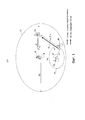
Фиг. 1 представляет диаграмму, иллюстрирующую схему распределения спектра для совместного использования.FIG. 1 is a diagram illustrating a spectrum sharing scheme for sharing.
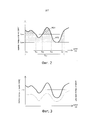
Фиг. 2 представляет диаграмму, иллюстрирующую пример известного способа управления мощностью передач вторичной системы связи.FIG. 2 is a diagram illustrating an example of a known transmission power control method of a secondary communication system.
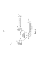
Фиг. 3 представляет диаграмму, иллюстрирующую новую модель учета помех концептуально.FIG. 3 is a diagram illustrating a new interference accounting model conceptually.
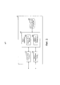
Фиг. 4 представляет схему, иллюстрирующую пример конфигурации системы управления связью согласно одному из вариантов.FIG. 4 is a diagram illustrating an example configuration of a communication management system according to one embodiment.
Фиг. 5 представляет схему, иллюстрирующую пример конфигурации устройства управления связью.FIG. 5 is a diagram illustrating a configuration example of a communication control device.
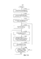
Фиг. 6 представляет логическую схему, иллюстрирующую пример общей последовательности операций процесса управления связью.FIG. 6 is a flowchart illustrating an example of a general flow of a communication control process.
Фиг. 7 представляет логическую схему, иллюстрирующую пример подробной последовательности операций процесса построения формулы для вычисления мощности.FIG. 7 is a flow diagram illustrating an example of a detailed flowchart of a process for constructing a formula for calculating power.
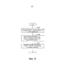
Фиг. 8 представляет логическую схему, иллюстрирующую другой пример подробной последовательности операций процесса построения формулы для вычисления мощности.FIG. 8 is a flow diagram illustrating another example of a detailed flowchart of a process for constructing a formula for calculating power.
Осуществление изобретенияThe implementation of the invention
Далее предпочтительные варианты настоящего изобретения будут рассмотрены подробно со ссылками на прилагаемые чертежи. Отметим, что в настоящем описании и на чертежах элементам, имеющим по существу одинаковые функции и структуры, присвоены одни и те же позиционные обозначения, а повторное пояснение опущено.Next, preferred embodiments of the present invention will be discussed in detail with reference to the accompanying drawings. Note that in the present description and in the drawings, elements having substantially the same functions and structures are assigned the same reference signs, and a second explanation is omitted.
Кроме того, описание будет дано в следующем порядке.In addition, a description will be given in the following order.
I. Общий обзорI. General overview
1-1. Распределение спектра для совместного использования1-1. Spectrum sharing
1-2. Техническая проблема1-2. Technical problem
1-3. Новая модель учета помех1-3. New jamming model
II. Пример конфигурации системы управления связьюII. Communication Management System Configuration Example
2-1. Краткое описание системы2-1. Short description of the system
2-2. Пример конфигурации устройства управления связью2-2. Communication Management Device Configuration Example
2-3. Последовательность операций2-3. Sequence of operations
III. ЗаключениеIII. Conclusion
I. Общий обзорI. General overview
1-1. Распределение спектра для совместного использования1-1. Spectrum sharing
Фиг. 1 представляет диаграмму, иллюстрирующую схему распределения спектра для совместного использования в соответствии с технологией согласно настоящему изобретению. На фиг. 1 показана базовая станция (в дальнейшем именуемая базовой станцией PS) 10 первичной системы связи. Эта первичная система представляет собой систему беспроводной связи провайдера, обладающего лицензией на некоторый частотный канал. Базовая станция PS предоставляет услуги беспроводной связи одному или более терминалам (в дальнейшем именуемым терминалами PS) 14 в первичной системе связи, расположенным в соте 12, в частотном канале, на который имеется лицензия (далее - лицензированный канал). Здесь, когда число активных терминалов PS, расположенных в соте 12, мало, в частотных ресурсах первичной системы образуется излишек (неиспользуемые ресурсы). Если провайдер, не имеющий лицензии, совсем не может использовать частотный канал, защищенный для первичной системы, эффективность использования частотных ресурсов снижается. С другой стороны, если не имеющий лицензии провайдер может свободно оперировать в пределах своих собственных услуг беспроводной связи, возможно создание недопустимых помех для услуг беспроводной связи, которые предоставляет первичная система связи и которые должны быть, естественно, защищены. Таким образом, с точки зрения повышения эффективности использования частотных ресурсов? доказано, что не имеющий лицензии провайдер должен вторично использовать излишние частотные ресурсы первичной системы связи в пределах, не создающих недопустимых помех.FIG. 1 is a diagram illustrating a spectrum allocation scheme for sharing in accordance with the technology of the present invention. In FIG. 1 shows a base station (hereinafter referred to as a PS base station) 10 of a primary communication system. This primary system is a wireless communication system of a provider licensed for a certain frequency channel. A PS base station provides wireless services to one or more terminals (hereinafter referred to as PS terminals) 14 in a primary communication system located in
В примере, показанном на фиг. 1, базовая станция (в дальнейшем именуемая базовой станцией SS) 20, являющаяся главным узлом вторичной системы связи, и один или более терминалов (в дальнейшем именуемых терминалами SS) 24 вторичной системы связи расположены в соте 12 первичной системы связи. Базовая станция SS 20 является устройством управления связью, оперирующим во вторичной системе связи посредством вторичного использования частотного канала, защищенного в пользу первичной системы связи. Эта базовая станция SS 20 может быть, например, точкой радио доступа, базовой станцией фемтоячейки, базовой станцией «горячей зоны», удаленным радио блоком (remote radio head (RRH)), либо устройством какого-либо другого типа, обладающим функциями когнитивного радио. Здесь, например, когда передача беспроводного сигнала 26 от терминала SS 24 происходит в одно и то же время с передачей сигнала 16 нисходящей линии от базовой станции PS 10, этот радиосигнал 26 может создавать взаимные помехи с сигналом 16 нисходящей линии в терминале PS 14. Вследствие этого, базовая станция SS 20 управляет мощностью передач терминала SS 24 таким образом, чтобы уровень помех, наблюдаемый в терминале PS14, не превышал допустимого уровня. Кроме того, базовая станция SS 20 управляет мощностью своих собственных передач таким же образом. Соответственно, реализуется безопасное распределение спектра для совместного использования между первичной системой связи и вторичной системой связи. Кроме того, когда вторичная система связи передает радиосигнал в моменты передач в восходящей линии (не в моменты передач в нисходящей линии), базовая станция PS 10 является целью защиты при распределении спектра для совместного использования.In the example shown in FIG. 1, the base station (hereinafter referred to as the base station SS) 20, which is the main node of the secondary communication system, and one or more terminals (hereinafter referred to as the SS terminals) 24 of the secondary communication system are located in the
1-2. Техническая проблема1-2. Technical problem
В общем случае, помехи, создаваемые для первичной системы связи, оценивают путем вычитания потерь в тракте между устройством, создающим помехи (например, терминалом SS 24, показанным на фиг. 1) из вторичной системы связи и устройством, для которого создаются помехи, (например, терминалом PS 14, показанным на фиг. 1) в первичной системе связи из мощности передач устройства, создающего помехи. Однако потери в тракте зависят не только от местонахождения терминала, но и от факторов замираний, таких как замирания вследствие многолучевого распространения и замирания вследствие затенения, и изменяются во времени. Поэтому трудно оценить потери в тракте в коротком цикле. Вследствие этого, согласно существующему способу вычисляют среднюю величину или минимальную величину оценки потерь в тракте за каждый период времени заданной продолжительности и управляют мощностью передач во вторичной системе связи на основе индикатора этих потерь.In general, the interference caused to the primary communication system is estimated by subtracting the path loss between the interfering device (for example, the
Фиг. 2 представляет схему, иллюстрирующую пример существующего способа управления мощностью во вторичной системе связи. На фиг. 2 по горизонтальной оси отложено время, а по вертикальной оси оценка величины потерь в тракте, и построен график изменений оценочной величины потерь в тракте в функции времени. Согласно существующему способу, например, вычисляют среднюю величину Lave или минимальную величину Lwrst оценки потерь в тракте за период времени TL0. Затем, используя найденную среднюю величину Lave или минимальную величину Lwrst, определяют мощность передач во вторичной системе связи в пределах, не создающих помех, превышающих допустимый уровень, для первичной системы связи.FIG. 2 is a diagram illustrating an example of an existing power control method in a secondary communication system. In FIG. 2, time is plotted on the horizontal axis, and the path loss is estimated on the vertical axis, and a graph of changes in the estimated path loss as a function of time is plotted. According to the existing method, for example, the average value L ave or the minimum value L wrst of the path loss estimate over a time period TL 0 is calculated. Then, using the found average value L ave or the minimum value L wrst , the transmission power in the secondary communication system is determined within the limits not creating interference exceeding the permissible level for the primary communication system.
Здесь, например, в периоды времени от момента T00 до момента Т01, от момента Т02 до момента Т03, и от момента Т04 до момента Т05, оценочная величина потерь в тракте превышает среднюю величину Lave. Таким образом, если мощность передач во вторичной системе связи определять с использованием средней величины Lave, тогда мощность передач, соответствующая заштрихованной на чертеже области RO1, не используется, хотя на самом деле ее использовать можно. Кроме того, если мощность передач во вторичной системе определять согласно минимальной величине Lwrst, тогда мощность передач, соответствующая обеим областям - области RO1 и «заштрихованной» на чертеже точками области RO2, не используется, хотя на самом деле ее использовать можно. Эту неэффективность можно разрешить путем укорочения периода TL0. Однако недостатком такого решения является увеличение сигнализационных издержек, сопровождающих оценку потерь в тракте и передачу соответствующих сообщений обратной связи в коротком цикле.Here, for example, in periods of time from time T 00 to time T 01 , from time T 02 to time T 03 , and from time T 04 to time T 05 , the estimated path loss exceeds the average value L ave . Thus, if the transmission power in the secondary communication system is determined using the average value L ave , then the transmission power corresponding to the shaded region RO1 in the drawing is not used, although it can actually be used. In addition, if the transmission power in the secondary system is determined according to the minimum value L wrst , then the transmission power corresponding to both regions — the regions RO1 and the regions “RO2” shaded by the dots — is not used, although it can actually be used. This inefficiency can be resolved by shortening the TL 0 period. However, the disadvantage of this solution is the increase in signaling costs accompanying the estimation of path losses and the transmission of corresponding feedback messages in a short cycle.
1-3. Новая модель учета помех1-3. New jamming model
1. Основные принципы1. Basic principles
Таким образом, технология согласно настоящему изобретению предлагает новую модель учета помех для управления мощностью передач с использованием вместо потерь в тракте индекса замираний, оценить который легче, чем потери в тракте. Фиг. 3 представляет диаграмму, иллюстрирующую новую модель учета помех концептуально. В примере, показанном на фиг. 3, график, выполненный штриховой линией, представляет девиацию оценочной величины потерь в тракте. В общем случае, когда вклад замираний изменяется, вариации потерь в тракте изменяются вместе с самими потерями в тракте. Таким образом, оценочная величина потерь в тракте и девиация этой величины коррелированны одна с другой. Поэтому в новой модели учета помех параметр, именуемый «индекс замираний» и относящийся к девиации оценочной величины потерь в тракте, используется для построения формулы для вычисления мощности в функции от индекса замираний. Формула для вычисления мощности построена с использованием так называемого «принципа заполнения водой». В этом случае мгновенное значение индекса замираний оценивают простым способом и подставляют оценку мгновенного значения в формулу для вычисления мощности, чтобы определить мощность передач вторичной системы. Поэтому мощность передач вторичной системы может быть увеличена на величину, соответствующую областям RO1 и RO2, показанным на фиг. 2. Следовательно, можно повысить эффективность использования частотных ресурсов.Thus, the technology of the present invention provides a new interference accounting model for controlling transmission power using a fade index instead of path loss, which is easier to estimate than path loss. FIG. 3 is a diagram illustrating a new interference accounting model conceptually. In the example shown in FIG. 3, a dashed line graph represents the deviation of the estimated path loss. In the general case, when the contribution of fading changes, the variation in path loss changes along with the path loss itself. Thus, the estimated path loss and the deviation of this value are correlated with one another. Therefore, in the new model of noise accounting, a parameter called the “fading index” and relating to the deviation of the estimated value of the path loss is used to construct a formula for calculating the power as a function of the fading index. The formula for calculating power is built using the so-called "principle of filling with water." In this case, the instantaneous value of the fading index is estimated in a simple way and the instantaneous value estimate is substituted into the power calculation formula to determine the transmission power of the secondary system. Therefore, the transmission power of the secondary system can be increased by an amount corresponding to the regions RO1 and RO2 shown in FIG. 2. Therefore, it is possible to increase the efficiency of the use of frequency resources.
2. Построение формулы для вычисления мощности2. Building a formula for calculating power
В новой модели учета помех сделаны следующие допущения. Иными словами, в чертеже на фиг. 1 предполагается, что вероятность нахождения терминала PS 14 в любой точке ячейки 12 первичной системы связи одинакова. Кроме того, предполагается, что вероятность нахождения терминала SS 24 в любой точке круглой области с радиусом rss вокруг базовой станции SS 20 также одинакова. Здесь радиус ячейки 12 равен RC, расстояние между базовой станцией PS 10 и терминалом PS 14 равно rрр, расстояние между базовой станцией PS 10 и базовой станцией SS 20 равно rps, расстояние между базовой станцией SS 20 и терминалом SS 24 равно rss, расстояние между терминалом SS 24 и терминалом PS 14 равно rsp, угол между трактом (лучом) от базовой станции PS 10 к терминалу PS 14 и трактом (лучом) от базовой станции PS 10 к базовой станции SS 20 равен θ и угол между лучом от базовой станции SS 20 к базовой станции PS 10 и лучом от базовой станции SS 20 к терминалу SS 24 равен φ. Кроме того, индекс замираний для сигнала помех от терминала SS 24 к терминалу PS 14 равен ξsp. Расстояние между узлами и функция совместной плотности вероятности для узла связаны Формулой (1) ниже.The following assumptions are made in the new interference accounting model. In other words, in the drawing of FIG. 1, it is assumed that the probability of finding the
Математическое выражениеMathematical expression

Если мощность передач, исходящих от передающей станции (в дальнейшем именуется передающая станция SS; например, терминал SS 24) вторичной системы связи, отстоящей от базовой станции SS 20 на расстояние rss, обозначена PS (rss, ξSP) в качестве функции индекса ξSP замираний, то, поскольку величины r и ξ независимы, средняя величина потерь отношения сигнала к шумам и помехам (SINR) для приемной станции (в дальнейшем именуется приемная станция; например, терминал PS 14) в первичной системе связи может быть выражена Формулой (2) ниже.If the power of the transmissions coming from the transmitting station (hereinafter referred to as the transmitting station SS; for example, the terminal SS 24) of the secondary communication system, spaced apart from the
Математическое выражение 2Mathematical expression 2

гдеWhere
![]()
![]()
В Формуле (2) функция fξsp (ξ) представляет гауссовское распределение с нулевым средним значением при стандартном отклонении σ [дБ] индекса замираний. В Формуле (3) параметр GUE обозначает коэффициент усиления антенны терминала, Np обозначает мощность шумов в устройстве, для которого создаются помехи. Функция En {Gpath, UE, UE (rSP)} представляет собой ожидаемую величину потерь в тракте, иными словами, вычисленную функцию совместной плотности вероятности для расстояния между узлами, выраженную Формулой (1).In Formula (2), the function f ξsp (ξ) represents a Gaussian distribution with a zero mean value with a standard deviation σ [dB] of the fading index. In Formula (3), the parameter G UE denotes the gain of the terminal antenna, N p denotes the noise power in the device for which interference is generated. The function En {G path , UE, UE (r SP )} represents the expected value of the path loss, in other words, the calculated function of the joint probability density for the distance between nodes, expressed by Formula (1).
Здесь средняя величина отношения сигнал/шум (SIR) для приемной станции (в дальнейшем именуемой приемная станция SS) во вторичной системе связи представляет собой функцию индекса ξsp замираний и расстояния rss, как это выражено в следующих формулах.Here, the average signal-to-noise ratio (SIR) for the receiving station (hereinafter referred to as the receiving station SS) in the secondary communication system is a function of the fading index ξ sp and the distance r ss , as expressed in the following formulas.
Математическое выражение 3Mathematical expression 3
![]()
![]()
гдеWhere

В формуле (5), Рр обозначает мощность передач базовой станции PS 10, GBS обозначает коэффициент усиления антенны базовой станции PS 10 и Gpath, UE, UE (rss) обозначает потери в тракте между передающей станцией SS и приемной станцией SS. Функция En {1/Gpath, BS, UE (rps)} представляет собой ожидаемое значение обратной величины потерь в тракте, вычисленной на основе функции совместной плотности вероятности для расстояния между узлами, как в Формуле (1).In formula (5), P p denotes the transmit power of the
На основе неравенства Йенсена верхняя граница эргодической пропускной способности может быть выражена следующей формулой. Кроме того, единицей измерения эргодической пропускной способности является (бит/с)/Гц (bps/Hz).Based on Jensen's inequality, the upper limit of ergodic capacity can be expressed by the following formula. In addition, the unit of measure for ergodic bandwidth is (bps) / Hz (bps / Hz).
Математическое выражение 4Mathematical expression 4

В последующем описании суффиксы будут для краткости опущены. Задача оптимизации с заданными ограничениями, как в следующих формулах, была сформулирована с целью максимизации верхней границы пропускной способности вторичной системы связи.In the following description, suffixes will be omitted for brevity. The optimization problem with the given restrictions, as in the following formulas, was formulated with the aim of maximizing the upper limit of the throughput of the secondary communication system.
Математическое выражение 5Mathematical expression 5

гдеWhere
![]()
![]()
В Формуле (8), SINRloss, tol обозначает допустимую величину потерь отношения SINR для первичной системы связи. Параметр к является параметром модели учета помех, вычисленный по Формуле (3). Оператор Лагранжа для решения задачи оптимизации с заданными ограничениями согласно Формуле (7) представлен следующей формулой.In Formula (8), SINR loss, tol denotes the permissible loss of SINR ratio for the primary communication system. The parameter k is a parameter of the model of noise accounting, calculated according to Formula (3). The Lagrange operator for solving the optimization problem with given constraints according to Formula (7) is represented by the following formula.
Математическое выражение 6Mathematical expression 6

В результате дифференцирования оператора Лагранжа по PS (ξ), получается следующая формула.As a result of differentiation of the Lagrange operator with respect to P S (ξ), we obtain the following formula.
Математическое выражение 7Mathematical expression 7

Когда уравнение для PS (ξ) решено при ограничении PS(ξ)≥0, решение по принципу заполнения водой, имеющее величину ξ0 порога отсечки, получают по следующей формуле.When the equation for P S (ξ) is solved with the restriction of P S (ξ) ≥0, a solution based on the principle of filling with water having a value ξ 0 of the cutoff threshold is obtained by the following formula.
Математическое выражение 8Mathematical expression 8

Формула (11) указывает, что мощность PS (rss, ξsp) равна нулю в период времени, когда индекс ξSP замираний между передающей станцией SS (устройство-источник помех) и терминалом PS (устройство, для которого создаются помехи) превосходит величину ξ0 [дБ] порога отсечки. Следовательно, удовлетворяется ограничение, что потери отношения SINR, наблюдаемые в терминале PS, меньше допустимого уровня SINRloss, tol. Величину ξ0 порога отсечки вычисляют посредством следующего уравнения, записанного в замкнутой форме.Formula (11) indicates that the power P S (r ss , ξsp ) is equal to zero during the time period when the fading index ξ SP between the transmitting station SS (the source of interference) and the terminal PS (the device for which interference is generated) exceeds ξ 0 [dB] cutoff threshold. Therefore, the restriction is satisfied that the SINR loss observed in the PS terminal is less than the allowable SINR loss level , tol . The value ξ 0 of the cutoff threshold is calculated by the following equation, written in closed form.
Математическое выражение 9Mathematical expression 9

Кроме того, в предположении гауссовского распределения с нулевой средней (нормальное распределение) Формула (12) может быть эквивалентно заменена следующей формулой с использованием заданного стандартного отклонения σ [дБ] для индекса ξsp замираний.In addition, assuming a Gaussian distribution with a zero mean (normal distribution), Formula (12) can be equivalently replaced by the following formula using a given standard deviation σ [dB] for the index ξ sp of fading.
Математическое выражение 10

В Формуле (13), Q(⋅) представляет собой функцию Q вероятности больших отклонений для стандартного нормального распределения.In Formula (13), Q (⋅) is the function Q of the probability of large deviations for the standard normal distribution.
В новой модели учета помех величина £о порога отсечки может быть рассчитана путем вычисления параметров к (rss), χ(rss) и у и решения уравнений по Формуле (12) или Формуле (13). Тогда формула вычисления мощности (Формула (11)) для вычисления мощности PS (rss, ξsp) передач может быть построена с использованием вычисленной величины ξ0 порога отсечки. Аргументов формулы (11) для вычисления мощности является только индекс ξsp замираний. Поскольку предполагается, что взаимное расположение первичной системы связи и вторичной системы связи является вероятностным, реально измеренная величина потерь в тракте между передающей станцией SS и терминалом PS не может быть использована при построении формулы для вычисления мощности.In the new model for taking noise into account, the cutoff threshold value £ o can be calculated by calculating the parameters k (r ss ), χ (r ss ) and y and solving the equations according to Formula (12) or Formula (13). Then the power calculation formula (Formula (11)) for calculating the transmission power P S (r ss , ξ sp ) of the transmissions can be constructed using the calculated value ξ 0 of the cutoff threshold. The arguments of formula (11) for calculating the power is only the index ξ sp of fading. Since it is assumed that the relative position of the primary communication system and the secondary communication system is probabilistic, the actually measured path loss between the transmitting station SS and the PS terminal cannot be used in constructing a formula for calculating power.
В соответствии с технологией согласно настоящему изобретению после построения формулы для вычисления мощности можно определить мощность передач, излучаемую передающей станцией SS, с использованием индекса ξsp замираний, оцениваемого на основе относительного перемещения устройства, создающего помехи.According to the technology of the present invention, after constructing a formula for calculating the power, it is possible to determine the transmission power emitted by the transmitting station SS using the fading index ξ sp , estimated based on the relative displacement of the interfering device.
3. Оценка индекса замираний3. Estimation of the index of fading
Мгновенное значение индекса замираний может быть оценено, например, с использованием способа оценки замираний на основе метода наименьших квадратов, который будет рассмотрен ниже. Этот способ оценки замираний на основе метода наименьших квадратов был описан, например, в статьях «Экспериментальный анализ совместных статистических свойств разброса азимута, разброса задержки и замираний вследствие затенения» ("Experimental analysis of the joint statistical properties of azimuth spread, delay spread, and shadow fading" (A. Algans, К.I. Pedersen, and P.E. Mogensen, IEEE Journal on Selected Areas in Communication, vol. 20, no. 3, pp. 523-531, April 2002)) и «Корреляция крупномасштабных параметров между объектами и внутри объекта, полученных путем измерения макроячеек на частоте 1800 МГц» ("Inter - and intrasite correlations of large-scale parameters from macrocellular measurements at 1800 mhz" (N. Jalden, P. Zetterberg, B. Ottersten, and L. Garcia, EURASIP Journal on Wireless Communications and Networking, 2007)).The instantaneous value of the fade index can be estimated, for example, using the least squares fading estimation method, which will be discussed below. This least-squares method of estimating fading has been described, for example, in the articles “Experimental analysis of the joint statistical properties of azimuth spread, delay spread, and shadow fading "(A. Algans, K. I. Pedersen, and PE Mogensen, IEEE Journal on Selected Areas in Communication, vol. 20, no. 3, pp. 523-531, April 2002)) and" Correlation of large-scale parameters between objects and inside an object obtained by measuring macrocells at a frequency of 1800 MHz "(" Inter - and intrasite correlations of large-scale parameters from macroc ellular measurements at 1800 mhz "(N. Jalden, P. Zetterberg, B. Ottersten, and L. Garcia, EURASIP Journal on Wireless Communications and Networking, 2007)).
Когда расстояние между устройством, создающим помехи, и устройством, для которого создаются помехи, равно d, соотношение между индексом hsh замираний и зависящими от расстояния потерями hch (d) в тракте согласно способу оценки замираний на основе метода наименьших квадратов выражено следующей формулой. Математическое выражение 11When the distance between interfering devices, and a device that creates the interference is equal to d, the relation between the index h sh fading and independent of distance losses h ch (d) in the path according to a method of estimating the fading on the basis of the least squares method expressed by the following formula. Mathematical expression 11
![]()
![]()
Предполагается, что расстояние d равно сумме опорного расстояния d0 и приращения (изменения) di относительного расстояния по сравнению с опорным расстоянием d0 (d=d0+di). Тогда Формулу (14) переписывают следующим образом.It is assumed that the distance d is equal to the sum of the reference distance d 0 and the increment (change) d i of the relative distance compared to the reference distance d 0 (d = d 0 + d i ). Then Formula (14) is rewritten as follows.
Математическое выражение 12

Здесь разложение в ряд Тейлора для х в интервале -1<х≤1 представлено следующим образом.Here, the Taylor series expansion for x in the interval -1 <x≤1 is presented as follows.
Математическое выражение 13Mathematical expression 13

Соответственно, когда разложение в ряд Тейлора осуществляется для функции log10(1+di/d0) в диапазоне -1<di/d0<1, то с упором на третий член Формулы (15) получена следующая приближенная формула. Кроме того, отброшены третий и последующие члены разложения в ряд Тейлора.Accordingly, when the expansion in the Taylor series is carried out for the function log 10 (1 + d i / d 0 ) in the range -1 <d i / d 0 <1, then, with emphasis on the third term of Formula (15), the following approximate formula is obtained. In addition, the third and subsequent members of the Taylor series expansion were dropped.
Математическое выражение 14
![]()
![]()
гдеWhere
![]()
![]()
Аппроксимирующая формула, полученная в результате дальнейшего обобщения Формулы (17), выглядит следующим образом. Математическое выражение 15The approximating formula obtained as a result of a further generalization of Formula (17) is as follows. Mathematical expression 15
![]()
![]()
Здесь, при условии, что m задает приращение di относительного расстояния по сравнению с опорным расстоянием d0 и что подготовлены результаты измерения мощности Pi приема на расстоянии d=d0+di (i=1, 2, …, m), построена следующая система уравнений. Здесь также предполагается, что |di|<d0 и что m в достаточной степени больше n.Here, provided that m defines the increment d i of the relative distance compared to the reference distance d 0 and that the results of measuring the receiving power P i at a distance d = d 0 + d i (i = 1, 2, ..., m) are prepared, the following system of equations is constructed. It is also assumed here that | di | <d 0 and that m is sufficiently larger than n.
Математическое выражение 16

В результате решения уравнения Формулы (19) методом наименьших квадратов получают вектор а=(а0, a1, …, an) коэффициентов, выраженный следующей формулой.As a result of solving the equation of Formula (19) by the least squares method, we obtain the vector a = (a 0 , a 1 , ..., a n ) of the coefficients, expressed by the following formula.
Математическое выражение 17Mathematical expression 17
![]()
![]()
В результате, если вектор а=(а0, a1, …, аn) коэффициентов может быть получен заранее путем решения системы уравнений по Формуле (19), мгновенное значение индекса замираний можно оценить на основе расстояния по вертикали между средней мощностью приема и величиной оценки зависящих от расстояния потерь в тракте, полученной на основе полинома (18) для конкретного относительного расстояния di. Затем можно определить мощность передач, исходящих от передающей станции SS, путем подстановки оценки мгновенного значения индекса замираний в формулу (11) для вычисления мощности.As a result, if the vector a = (a 0 , a 1 , ..., n ) of the coefficients can be obtained in advance by solving the system of equations according to Formula (19), the instantaneous value of the fading index can be estimated based on the vertical distance between the average receiving power and the magnitude of the distance-dependent path loss obtained from polynomial (18) for a specific relative distance d i . You can then determine the power of the transmissions coming from the transmitting station SS by substituting the estimate of the instantaneous fading index into formula (11) to calculate the power.
Кроме того, расчет оценки мгновенного значения индекса замираний не ограничивается рассмотренным здесь примером и может быть выполнен другими способами.In addition, the calculation of the estimation of the instantaneous value of the fading index is not limited to the example considered here and can be performed in other ways.
II. Пример конфигурации системы управления связьюII. Communication Management System Configuration Example
В этом разделе будет рассмотрен пример варианта системы управления связью, которая управляет мощностью передач во вторичной системе связи с использованием описанной выше модели учета помех.In this section, we will consider an example of a variant of a communication control system that controls the transmission power in a secondary communication system using the interference accounting model described above.
2-1. Общий обзор системы2-1. General system overview
На фиг. 4 представлена схема, иллюстрирующая конфигурацию системы 1 управления связью согласно одному из вариантов. Как показано на фиг. 4, система 1 управления связью содержит базовую станцию PS 10, терминал PS 14, базовую станцию SS 20, терминал SS 24 и сервер 30 данных.In FIG. 4 is a diagram illustrating the configuration of a
Сервер 30 данных представляет собой серверное устройство, имеющее базу данных для управления вторичным использованием частотного канала во вторичной системе связи. Этот сервер данных собирает системную информацию относительно первичной системы связи от базовой станции PS 10. Эта системная информация, собранная от базовой станции PS 10, может содержать, например, местонахождение базовой станции PS 10, радиус ячейки, коэффициент усиления антенны, мощность шумов, мощность передач базовой станции PS 10, допустимые потери отношения SINR и другую подобную информацию. Затем, когда начинает работать вторичная система связи, сервер 30 передает системную информацию относительно первичной системы связи в адрес базовой станции SS 20 в ответ на запрос от этой базовой станции SS 20. Сервер 30 данных может сообщить в адрес базовой станции SS 20 такую информацию, как спектральная маска и частотный канал для использования вторичной системой связи. Связь между базовой станцией SS 20 и сервером 30 данных может осуществляться, например, через какую-нибудь сеть связи, такую как Интернет. Кроме того, базовая станция SS 20 может непосредственно принимать системную информацию относительно первичной системы связи от базовой станции PS 10.The
В рассматриваемом варианте базовая станция SS 20 работает в качестве устройства управления связью, которое управляет мощностью передач базовой станции SS 20 и мощностью передач терминала SS 24. Базовая станция SS 20 определяет мощность передач, исходящих от передающей станции SS (например, от базовой станции SS 20 или терминала SS 24), с использованием мгновенного значения индекса замираний согласно рассмотренной выше модели учета помех. После построения формулы для вычисления мощности, использующей принцип заполнения водой, можно периодически обновлять в коротком цикле только индекс замираний, подставляемый в эту построенную формулу для вычисления мощности. Формула вычисления мощности может быть построена заново, когда помехи, наблюдаемые в первичной системе связи, превышают допустимый уровень (иными словами, происходит нарушение допустимых пределов помех). Терминал PS 14 (или базовая станция PS 10) передает отчет о наблюдаемом уровне помех периодически или в случае обнаружения превышения допустимого уровня помех. Базовая станция SS 20 принимает отчет о наблюдаемом уровне помех и может построить заново (иными словами, модифицировать) формулу для вычисления мощности в случае необходимости. Соответственно, защита первичной системы связи оказывается усилена.In the present embodiment, the
Кроме того, функции устройства управления связью, осуществляющего управление мощностью передач во вторичной системе связи, вместо базовой станции SS 20 может выполнять сервер 30 данных или какой-либо другой узел.In addition, the functions of the communication control device that controls transmission power in the secondary communication system, instead of the
2-2. Пример конфигурации устройства управления связью2-2. Communication Management Device Configuration Example
На фиг. 5 представлена схема, иллюстрирующая пример конфигурации устройства 20 управления связью. Как показано на фиг. 5, устройство 20 управления связью содержит модуль 110 связи с сетью, модуль 120 беспроводной связи, запоминающее устройство 130, и модуль 140 управления. Этот модуль 140 управления содержит модуль 150 сбора данных и модуль 160 управления мощностью.In FIG. 5 is a diagram illustrating a configuration example of a
Модуль 100 связи с сетью представляет собой интерфейс связи для осуществления связи между устройством 20 управления связью и сервером 30 данных. Связь между устройством 20 управления связью и сервером 30 данных может быть реализована посредством проводной связи, беспроводной связи или с использованием сочетания этих видов связи.The network communication unit 100 is a communication interface for communicating between the
Модуль 120 беспроводной связи представляет собой интерфейс беспроводной связи для устройства управления связью с целью предоставления услуг беспроводной связи одному или более терминалам SS 24. Этот модуль 120 беспроводной связи передает радиосигнал в частотном канале, защищенном в пользу первичной системы, с использованием мощности передачи, которая может быть определена в соответствии с рассмотренной выше моделью учета помех.The
Запоминающее устройство 130 хранит программу и данные для работы устройства 20 управления связью с использованием носителя записи, такого как жесткий диск или полупроводниковое запоминающее устройство. Например, запоминающее устройство 130 хранит системную информацию относительно первичной системы связи, которая была получена от сервера 30 данных. Кроме того, запоминающее устройство 130 хранит параметр, подготовленный или вычисленный для мощности передач во вторичной системе связи.A
Модуль 140 управления соответствует процессору, такому как центральный процессор (CPU) или цифровой процессор сигнала (DSP). Модуль 140 управления активизирует различные функции устройства 20 управления связью путем выполнения программы, хранящейся в запоминающем устройстве 130 или на другом носителе записи.The
Модуль 150 сбора данных осуществляет сбор данных, необходимых для управления мощностью передач посредством модуля 160 управления мощностью. Например, когда вторичная система начинает работать, модуль 150 сбора данных получает системную информацию о первичной системе от сервера 30 данных. Кроме того, модуль 150 сбора данных осуществляет сбор такой информации, как местонахождение, коэффициент усиления антенны и максимальная мощность передач, относительно терминала SS 24, присоединившегося к вторичной системе связи.
Модуль 160 управления мощностью определяет мощность передач беспроводного сигнала, передаваемого от устройства, создающего помехи, из вторичной системы связи, таким образом, чтобы не создавать помех, превышающих допустимый уровень, для работы устройства, для которого создаются помехи, в первичной системе связи. Кроме того, если терминал SS 24 передает беспроводной сигнал в моменты, когда происходят передачи сигнала нисходящей линии в первичной системе связи, терминал SS 24 является устройством, создающим помехи, а терминал PS 14 является устройством, для которого создаются помехи. С другой стороны, если терминал SS 24 передает беспроводной сигнал в моменты, когда происходят передачи сигнала восходящей линии в первичной системе связи, базовая станция PS 10 оказывается устройством, для которого создаются помехи. Когда базовая станция SS 20 передает радиосигнал, эта базовая станция SS 20 является устройством, создающим помехи.The
Более конкретно, модуль 160 управления мощностью определяет мощность передач устройства, создающего помехи, с использованием мгновенного значения индекса замираний, оцениваемого на основе приращения (изменения) относительного расстояния между устройством, создающим помехи, и устройством, для которого создаются помехи, в соответствии с рассмотренной выше моделью учета помех. Мгновенное значение индекса замираний оценивают периодически в коротком цикле и динамически обновляют величину мощности передач с использованием полученной оценки мгновенного значения. Мощность передач определяют путем подстановки мгновенного значения индекса замираний в рассмотренную выше формулу (11) для вычисления мощности, воплощающую принцип заполнения водой, например. Величина ξ0 порога отсечки в формуле для вычисления мощности зависит от девиации замираний и вычисляется с использованием параметров κ, χ и γ модели учета помех.More specifically, the
Мгновенное значение индекса замираний можно оценивать в устройстве 20 управления связью. В альтернативном варианте мгновенное значение индекса замираний можно оценивать в других устройствах (например, в индивидуальном терминале SS 24). В первом случае модуль 160 управления мощностью периодически оценивает мгновенное значение индекса замираний применительно к каждому устройству-источнику помех на основе изменения относительного расстояния до устройства, создающего помехи, иными словами, величины относительного перемещения (отсчитываемого от опорной точки), соответствующего рассмотренному выше параметру di. В последнем случае мгновенное значение индекса замираний оценивают в каком-либо устройстве, после чего оценку мгновенного значения это устройство передает, а модуль 110 связи с сетью принимает указанную оценку.The instant value of the fade index can be estimated in the
Модуль 160 управления мощностью передает каждому устройству, создающему помехи, команду использовать динамически обновляемую величину мощности передачи (или меньшую мощность передачи). В результате пропускная способность связи во вторичной системе связи оказывается оптимизирована в таких пределах, где потери отношения SINR, выраженные Формулой (2), не превышают допустимого уровня потерь отношения SINR для первичной системы связи. Однако рассмотренная выше модель помех основана на вероятностном подходе и не может полностью «обнулить» риск возникновения недопустимых помех. Поэтому модуль 160 управления мощностью заново строит формулу вычисления мощности, когда динамически обновляемая мощность передач приводит к созданию помех, превосходящих допустимый уровень помех применительно к устройству, для которого создаются помехи. Возникновение помех, превосходящих допустимый уровень, можно определить после приема отчета о наблюдениях от устройства, для которого создаются помехи (например, от терминала PS 14).
Например, запоминающее устройство 130 предварительно сохраняет преобразовательную таблицу, отображающую индикатор качества, измеренный в устройстве, для которого создаются помехи, на параметр, входящий в состав формулы для вычисления мощности. Здесь в качестве индикатора качества можно использовать какой-либо индикатор, зависящий от величины помех. Например, таким индикатором качества может быть абсолютная величина помех, относительная величина помех, отсчитываемая от допустимого уровня, абсолютную величину потерь отношения SINR, относительную величину потерь отношения SINR, отсчитываемую от допустимого уровня потерь отношения SINR, или другой подобный параметр. В качестве указанного параметра, входящего в состав формулы для вычисления мощности, можно использовать, например, один или несколько из совокупности рассмотренных выше параметров κ, χ и γ модели учета помех и величины ξ0 порога отсечки. Тогда, при приеме отчета о наблюдениях помех от устройства, для которого создаются помехи, модуль 160 управления мощностью заново строит формулу для вычисления мощности в соответствии с индикатором качества, входящим в состав отчета о наблюдениях помех, со ссылками на преобразовательную таблицу, сохраняемую в запоминающем устройстве 130. Например, когда при наблюдениях обнаружены недопустимые помехи, уровень которых превышает допустимый уровень на величину ΔI, величину ξ0 порога отсечки можно уменьшить на величину ΔI.For example, the
2-3. Последовательность операций2-3. Sequence of operations
1/ Общая последовательность1 / General sequence
Фиг. 6 представляет логическую схему, иллюстрирующую пример общей последовательности операций процесса управления связью согласно рассматриваемому варианту.FIG. 6 is a flowchart illustrating an example of a general flowchart of a communication control process according to the present embodiment.
Как показано на фиг. 6, сначала, когда вторичная система связи начинает работать, модуль 150 сбора данных, получает системную информацию относительно первичной системы связи от сервера 30 данных (этап S110). Кроме того, этот модуль 150 сбора данных, получает системную информацию относительно вторичной системы связи, такую как коэффициент усиления антенны и местонахождение устройства, создающего помехи (этап S120).As shown in FIG. 6, first, when the secondary communication system begins to operate, the
Затем модуль 160 управления мощностью получает вектор коэффициентов для оценки индекса замираний (этап S130). Этот вектор коэффициентов может быть предварительно вычислен посредством решения описанной выше системы уравнений (19) методом наименьших квадратов на стадии инициализации процесса управления (или раньше) на основе множества групп из измеренных значений мощности Pi приема и соответствующих приращений di (изменений) относительного расстояния до устройства, создающего помехи.Then, the
Далее модуль 160 управления мощностью выполняет построение формулы для вычисления мощности в соответствии с описанной выше моделью учета помех с использованием информации, полученной на этапах S110 и S120 (этап S140). Подробная последовательность операций будет дополнительно рассмотрена позднее.Next, the
Затем модуль 160 управления мощностью оценивает мгновенное значение ξsp индекса замираний относительно каждого устройства, создающего помехи, с использованием величины относительного смещения di каждого устройства, создающего помехи, от опорной точки и вектора коэффициентов, полученного на этапе S130 (этап S150). Кроме того, может быть выполнена оценка индивидуального мгновенного значения индекса замираний для каждого устройства, создающего помехи, после чего величина оценки может быть сообщена устройству 20 управления связью.Then, the
Далее модуль 160 управления мощностью вычисляет мощность передач для каждого устройства, создающего помехи, путем подстановки оценочной величины мгновенного значения ξsp индекса замираний в формулу для вычисления мощности, построенную на этапе S140, согласно новой модели учета помех (этап S160). Здесь устройство 20 управления связью сообщает вычисленную величину мощности передач каждому устройству, создающему помехи.Next, the
После этого каждое устройство, создающее помехи, передает беспроводной сигнал с использованием сообщенной ему величины мощности передачи (или меньшей мощности передачи) (этап S170). Здесь передаваемый беспроводной сигнал действует в качестве сигнала помех для первичной системы связи. Однако, поскольку мощностью передачи управляют в соответствии с рассмотренной выше моделью учета помех, потери отношения SINR для первичной системы связи остаются ниже допустимого уровня потерь отношения SINR, если только погрешность управления не окажется слишком большой.After that, each interfering device transmits a wireless signal using the transmit power (or less transmit power) communicated to it (step S170). Here, the transmitted wireless signal acts as an interference signal for the primary communication system. However, since the transmit power is controlled in accordance with the interference accounting model discussed above, the loss of the SINR ratio for the primary communication system remains below the acceptable level of loss of the SINR ratio, unless the control error is too large.
Затем модуль 160 управления мощностью определяет, не наблюдаются ли помехи, превосходящие допустимый уровень, в устройстве, для которого создаются помехи, в результате передачи радиосигнала на этапе S170 (этап S180). Например, если в устройстве, для которого создаются помехи, наблюдаются помехи, превышающие допустимый уровень, соответствующий отчет, сообщающий о появлении недопустимых помех, может быть принят модулем 110 связи с сетью.Then, the
Когда помехи, превосходящие допустимый уровень, не наблюдаются, процесс возвращается к этапу S150, после чего периодически повторяют оценку мгновенного значения индекса замираний и вычисление (обновление) величины мощности передач. Если наблюдаются помехи, превосходящие допустимый уровень, процесс возвращается к этапу S140, после чего заново выполняют построение формулы для вычисления мощности на основе индикатора качества, сообщенного в отчете о наблюдении.When no interference exceeding the acceptable level is observed, the process returns to step S150, after which the estimation of the instantaneous fading index value and the calculation (updating) of the transmission power are periodically repeated. If interference exceeding the acceptable level is observed, the process returns to step S140, and then the formula for calculating the power is again constructed based on the quality indicator reported in the observation report.
2. Построение формулы для вычисления мощности2. Building a formula for calculating power
Фиг. 7 представляет логическую схему, иллюстрирующую пример подробной последовательности операций процесса построения формулы для вычисления мощности на этапе S140, показанном на фиг. 6.FIG. 7 is a flowchart illustrating an example of a detailed flowchart of a process for constructing a formula for calculating power in step S140 shown in FIG. 6.
Как показано на фиг. 7, сначала модуль 160 управления мощностью вычисляет параметр к модели учета помех с использованием коэффициента усиления антенны терминала, мощности шумов в первичной системе связи и ожидаемой величины потерь в тракте (эта величина получена не в результате реальных измерений, а на основе вероятностного анализа) согласно Формуле (3) (этап S141).As shown in FIG. 7, first, the
Далее модуль 160 управления мощностью вычисляет параметр χ модели учета помех с использованием заданного стандартного отклонения σ для индекса замираний согласно Формуле (5) (этап S142).Next, the
Затем модуль 160 управления мощностью вычисляет параметр γ модели учета помех с использованием допустимого уровня потерь отношения SINR и параметра к модели учета помех, вычисленного на этапе S141, согласно Формуле (8) (этап S143).Then, the
Далее модуль 160 управления мощностью вычисляет величину ξ0 порога отсечки для принципа заполнения водой посредством решения уравнения по формуле (12) или (13) с использованием параметров χ и γ модели учета помех (этап S144).Next, the
Затем модуль 160 управления мощностью выполняет построение формулы (11) для вычисления мощности, отражающий принцип заполнения водой, с использованием параметра χ модели учета помех и величины ξ0 порога отсечки (этап S147).Then, the
3. Повторное построение формулы для расчета мощности3. Reconstructing the formula for calculating power
Фиг. 8 представляет логическую схему, иллюстрирующую другой пример подробной последовательности операций процесса построения формулы для вычисления мощности на этапе S140, показанном на фиг. 6. Например, процесс, представленный на фиг. 8, может быть осуществлен, когда происходит повторное построение формулы для вычисления мощности на основе индикатора качества, сообщенного в отчете о наблюдениях.FIG. 8 is a flowchart illustrating another example of a detailed flowchart of a process for constructing a formula for calculating power in step S140 shown in FIG. 6. For example, the process of FIG. 8 can be carried out when a re-construction of the formula for calculating power occurs based on the quality indicator reported in the observation report.
Как показано на фиг. 8, сначала модуль 160 управления мощностью получает индикатор качества, наблюдаемый в устройстве, для которого создаются помехи, из отчета о наблюдениях, принятого модулем 110 связи с сетью (этап S145).As shown in FIG. 8, first, the
Далее модуль 160 управления мощностью получает параметр модели учета помех, соответствующий принятому индикатору качества, посредством обращения к преобразовательной таблице, заранее сохраненной в запоминающем устройстве 130 (этап S146). Здесь, например, предполагается, что получены параметр χ и величина ξ0 порога отсечки.Next, the
Затем модуль 160 управления мощностью выполняет повторное построение формулы (11) для вычисления мощности, выражающей принцип заполнения водой, с использованием параметра χ модели учета помех и величины ξ0 порога отсечки (этап S147).Then, the
III. ЗаключениеIII. Conclusion
До сих пор варианты технологии согласно настоящему изобретению были описаны подробно со ссылками на фиг.1-8. В соответствии с рассмотренными выше вариантами величину мощности передач радиосигнала от устройства, создающего помехи определяют с использованием индекса замираний, который оценивают на основе приращения (изменения) относительного расстояния между устройством, создающим помехи и устройством, для которого создаются помехи. Это позволяет эффективно использовать запас увеличения мощности, создаваемый вариациями потерь в тракте, обусловленными замираниями, в устройстве-источнике помех, не требуя точной оценки потерь в тракте между системами путем интенсивного обмена сигналами. Соответственно пропускная способность связи во вторичной системе связи, использующей частотный канал, защищенный в пользу первичной системы связи, может быть оптимизирована при недопущении увеличения сигнализационных издержек.So far, technology options according to the present invention have been described in detail with reference to figures 1-8. In accordance with the above options, the magnitude of the transmit power of the radio signal from the interfering device is determined using the fading index, which is estimated based on the increment (change) in the relative distance between the interfering device and the interfering device. This makes it possible to efficiently use the margin of power increase created by variations in path loss due to fading in the source of interference, without requiring an accurate estimate of path loss between systems through intensive signal exchange. Accordingly, the communication bandwidth in a secondary communication system using a frequency channel protected in favor of the primary communication system can be optimized while avoiding an increase in signaling costs.
Кроме того, согласно описанным выше вариантам мощность передач определяют путем подстановки мгновенного значения индекса замираний в формулу для вычисления мощности, выражающую принцип заполнения водой. Мгновенное значение индекса замираний может обновляться в более коротком цикле, чем при использовании существующего способа. Таким образом, например, пропускная способность связи может быть увеличена посредством динамического увеличения мощности передач от устройства, создающего помехи в моменты, когда потери в тракте превышают среднюю величину за период времени. Кроме того, получена формула для вычисления мощности с использованием величины порога отсечки, зависящей от девиации замираний. Это позволяет предотвратить появление недопустимых помех в устройстве, для которого создаются помехи, путем обнуления выходной мощности устройства, создающего помехи в периоды времени, когда потери в тракте, изменяющиеся вследствие замираний, оказываются невелики.In addition, according to the options described above, the transmission power is determined by substituting the instant value of the fading index in the formula for calculating the power, which expresses the principle of filling with water. The instant value of the fading index can be updated in a shorter cycle than when using the existing method. Thus, for example, the communication bandwidth can be increased by dynamically increasing the transmission power from the device, which creates interference at times when the path loss exceeds the average value over a period of time. In addition, a formula is obtained for calculating power using the cutoff threshold value, which depends on the deviation of fading. This helps to prevent unacceptable interference in the device for which interference is created by zeroing the output power of the device that creates interference during periods of time when the path loss, which changes due to fading, is small.
Кроме того, согласно рассмотренным выше вариантам формулу для вычисления мощности обновляют, когда динамически изменяющаяся мощность передач создает помехи, превосходящие допустимый уровень. Таким образом, поскольку риск появления недопустимых помех, которые могут возникать из-за погрешностей в модели учета помех, уменьшен в результате применения обратной связи от устройства, для которого создаются помехи, можно реализовать более устойчивое и надежное подавление помех. Формулу для вычисления мощности можно обновлять с использованием преобразовательной таблицы, связывающей наблюдаемую величину индикатора качества с параметром модели учета помех. Вследствие этого можно уменьшить объем данных, передаваемых в контуре обратной связи.In addition, according to the above options, the formula for calculating the power is updated when the dynamically changing transmission power causes interference exceeding the allowable level. Thus, since the risk of unacceptable interference that may occur due to errors in the interference accounting model is reduced as a result of applying feedback from the device for which the interference is generated, more stable and reliable interference suppression can be implemented. The formula for calculating power can be updated using a conversion table linking the observed value of the quality indicator with the parameter of the interference accounting model. As a result, the amount of data transmitted in the feedback loop can be reduced.
С точки зрения «вторичного использования» услуги беспроводной связи в первичной системе связи и услуги беспроводной связи во вторичной системе связи могут представлять собой услуги разного типа или услуги одного и того же типа. Такими услугами беспроводной связи разного типа могут быть, например, два или более вида услуг беспроводной связи разного типа, выбранных из группы - услуги цифрового телевизионного вещания, услуги спутниковой связи, услуги мобильной связи, услуги доступа в локальную сеть беспроводной связи (LAN) и услуги одноранговой (Р2Р) связи. С другой стороны, к услугам беспроводной связи одного и того же типа могут относиться, например, связь между услугами в макросоте, предоставляемыми провайдером, и услугами в фемтосоте, которой оперирует сам абонент или оператор виртуальной сети мобильной связи (mobile virtual network operator (MVNO)), в области услуг мобильной связи. Кроме того, в услуги связи одного и того же типа может входить взаимодействие между услугами, предоставляемыми базовой станцией, и услугами, предоставляемыми ретрансляционной станцией (ретрансляционным узлом), чтобы «закрыть» спектральное окно, в рамках услуг связи на основе технологий WiMAX, LTE (долговременная эволюция (Long Term Evolution)), LTE-A (усовершенствованная LNE (LTE-Advanced)) или другой подобной технологии. В дополнение к этому, вторичная система связи может использовать несколько фрагментарных частотных диапазонов, агрегированных посредством технологии агрегирования спектра. Кроме того, вторичная система связи может представлять собой группу фемтосот, действующих в зоне обслуживания базовой станции, группы ретрансляционных станций или группы базовых станций небольшого или среднего размера, каждая из которых создает зоны обслуживания меньшего размера, чем обычная базовая станция. Рассмотренная в настоящем описании модель учета помех может быть широко применена ко всем таким типам режимов вторичного использования.From the point of view of “secondary use”, wireless communication services in the primary communication system and wireless communication services in the secondary communication system may be of different types or services of the same type. Such various types of wireless services can be, for example, two or more types of various types of wireless services selected from the group — digital television broadcasting services, satellite communications services, mobile communications services, access to a local wireless communication network (LAN), and services Peer-to-peer (P2P) communication. On the other hand, wireless communication services of the same type may include, for example, communication between services in a macro cell provided by a provider and services in a femto cell operated by a subscriber or a mobile virtual network operator (MVNO) ), in the field of mobile services. In addition, communication services of the same type may include interaction between the services provided by the base station and the services provided by the relay station (relay node) in order to “close” the spectral window within the framework of communication services based on WiMAX, LTE technologies ( Long Term Evolution), LTE-A (Advanced LNE (LTE-Advanced)), or other similar technology. In addition to this, the secondary communication system may use several fragmented frequency bands aggregated by spectrum aggregation technology. In addition, the secondary communication system can be a group of femtocells operating in the coverage area of a base station, a group of relay stations or a group of small or medium-sized base stations, each of which creates smaller coverage areas than a conventional base station. The interference accounting model described herein can be widely applied to all such types of secondary use modes.
Кроме того, модель учета помех, рассмотренная в настоящем описании, не ограничивается целями вторичного использования частотного канала, а может быть применена в разнообразных задачах снижения или устранения помех.In addition, the interference accounting model considered in the present description is not limited to the secondary use of the frequency channel, but can be used in a variety of tasks to reduce or eliminate interference.
Процесс вычислений, рассмотренный в настоящем описании, может быть реализован с использованием программного обеспечения, аппаратуры или с использованием сочетания программных и аппаратных средств. Программы, составляющие программное обеспечение, сохраняют заранее, например, на носителе записи, расположенном внутри или вне устройства. Затем, например, каждую программу загружают в запоминающее устройство с произвольной выборкой (ЗУПВ (RAM)) и выполняют в процессоре, таком как центральный процессор (CPU).The calculation process described in the present description can be implemented using software, hardware, or using a combination of software and hardware. Programs that make up the software are stored in advance, for example, on a recording medium located inside or outside the device. Then, for example, each program is loaded into a random access memory (RAM) and executed in a processor such as a central processing unit (CPU).
Предпочтительные варианты настоящего изобретения были рассмотрены выше со ссылками на прилагаемые чертежи, тогда как настоящее изобретение, безусловно, приведенными выше примерами не ограничивается. Специалист в рассматриваемой области может найти разнообразные изменения и модификации в пределах объема прилагаемой Формулы изобретения, и должно быть понятно, что все они естественным образом попадают в рамки технического объема настоящего изобретения.Preferred embodiments of the present invention have been discussed above with reference to the accompanying drawings, while the present invention is, of course, not limited to the above examples. A person skilled in the art can find various changes and modifications within the scope of the appended claims, and it should be understood that they all naturally fall within the technical scope of the present invention.
Кроме того, предлагаемая технология может быть конфигурирована, как указано ниже.In addition, the proposed technology can be configured as follows.
(1) Устройство управления связью, содержащее:(1) A communication control device comprising:
модуль управления мощностью для определения мощности передачи беспроводного сигнала, передаваемого устройством, создающим помехи, с использованием индекса замираний, оцененного на основе изменения относительного расстояния между устройством, создающим помехи, и устройством, которому создаются помехи.a power control module for determining a transmit power of a wireless signal transmitted by an interfering device using a fading index estimated based on a change in the relative distance between the interfering device and the interfered device.
(2) Устройство управления связью по (1), в котором(2) The communication control device according to (1), wherein
модуль управления мощностью выполнен с возможностью определения мощности передачи посредством подстановки индекса замираний в вычислительную формулу, выражающую принцип заполнения водой.the power control module is configured to determine transmission power by substituting the fading index into a computational formula expressing the principle of filling with water.
(3) Устройство управления связью по (2), в котором(3) The communication control device according to (2), wherein
вычислительная формула получена с использованием величины порога отсечки, зависящей от девиации замираний.The computational formula is obtained using the cutoff threshold value, which depends on the deviation of fading.
(4) Устройство управления связью по (2) или (3), в котором(4) A communication control device according to (2) or (3), wherein
модуль управления мощностью выполнен с возможностью динамического обновления величины мощности передачи с использованием мгновенного значения индекса замираний.the power control module is configured to dynamically update the transmit power value using the instant fade index value.
(5) Устройство управления связью по (4), в котором(5) The communication control device according to (4), wherein
модуль управления мощностью выполнен с возможностью обновления вычислительной формулы, при создании динамически обновляемой величиной мощности передачи помех, превосходящих допустимый уровень помех для устройства, которому создаются помехи.the power control module is configured to update the computational formula when creating a dynamically updated amount of interference power exceeding the allowable noise level for the device that is being interfered with.
(6) Устройство управления связью по (5), в котором(6) The communication control device according to (5), wherein
модуль управления мощностью выполнен с возможностью обновления вычислительной формулы с использованием индикатора качества, наблюдаемого в устройстве, которому создаются помехи, и со ссылками на преобразовательную таблицу, отображающую индикатор качества в параметр, входящий в состав вычислительной формулы.the power control module is configured to update the computational formula using the quality indicator observed in the interfered device and with reference to a conversion table displaying the quality indicator in a parameter included in the computational formula.
(7) Устройство управления связью по любому из (1)-(6), в котором(7) A communication control device according to any one of (1) to (6), wherein
индекс замираний оценивают посредством подстановки величины изменения относительного расстояния в оценочную формулу, коэффициенты которой вычислены предварительно на основе множества относительных расстояний и множества мощностей приема, измеренных для относительных расстояний, соответственно.the fading index is estimated by substituting the magnitude of the change in relative distance into an estimation formula, the coefficients of which are preliminarily calculated based on the set of relative distances and the set of reception powers measured for relative distances, respectively.
(8) Устройство управления связью по любому из (1)-(7), в котором(8) A communication control device according to any one of (1) to (7), wherein
устройство, которому создаются помехи, представляет собой приемную станцию первичной системы связи, аthe device to which the interference is created is a receiving station of the primary communication system, and
устройство, создающее помехи, представляет собой передающую станцию вторичной системы связи, использующую частотный канал, защищенный для первичной системы связи.the interfering device is a transmitting station of a secondary communication system using a frequency channel protected for the primary communication system.
(9) Устройство управления связью по (8), в котором(9) The communication control device according to (8), wherein
указанное устройство управления связью представляет собой передающую станцию вторичной системы связи.said communication control device is a transmitting station of a secondary communication system.
(10) Устройство управления связью по (8), в котором(10) The communication control device according to (8), wherein
указанное устройство управления связью представляет собой сервер, управляющий вторичным использованием частотного канала.the specified communication control device is a server that controls the secondary use of the frequency channel.
(11) Устройство управления связью по любому из (1)-(10), в котором(11) A communication control device according to any one of (1) to (10), wherein
модуль управления мощностью выполнен с возможностью оценки индекса замираний на основе изменений относительного расстояния.the power control module is configured to estimate the fading index based on changes in relative distance.
(12) Устройство управления связью по любому из (1)-(10), дополнительно содержащее:(12) A communication control device according to any one of (1) to (10), further comprising:
модуль связи, выполненный с возможностью приема оценки индекса замираний от устройства, оценившего индекс замираний на основе изменений относительного расстояния.a communication module configured to receive an estimate of the fade index from a device that estimates the fade index based on changes in relative distance.
(13) Способ управления связью, реализуемый устройством управления связью, управляющим мощностью передачи устройства, создающего помехи, содержащий этап, на котором:(13) A communication control method implemented by a communication control device controlling a transmission power of an interfering device, comprising:
определяют мощность передач беспроводного сигнала, излучаемого устройством, создающим помехи, с использованием индекса замираний, полученного путем оценки на основе изменений относительного расстояния между устройством, создающим помехи, и устройством, которому создаются помехи.determining the transmit power of the wireless signal emitted by the interfering device using the fading index obtained by estimating based on changes in the relative distance between the interfering device and the interfered device.
(14) Программа, в соответствии с которой компьютер, управляющий работой устройства управления связью, выполняет функции:(14) A program according to which a computer controlling the operation of a communication control device performs the functions of:
модуля управления мощностью, выполненного с возможностью определения мощности передачи радиосигнала, излучаемого устройством, создающим помехи, с использованием индекса замираний, полученного посредством оценки на основе изменений относительного расстояния между устройством, создающим помехи, и устройством, которому создаются помехиa power control module configured to determine the transmit power of the radio signal emitted by the interfering device using a fading index obtained by estimating based on changes in the relative distance between the interfering device and the interfering device
(15) Система управления связью, содержащая:(15) A communication management system comprising:
устройство беспроводной связи из состава второй системы беспроводной связи, расположенное в соте первой системы беспроводной связи; иa wireless communication device of a second wireless communication system located in a cell of a first wireless communication system; and
устройство управления связью, конфигурированное для определения мощности радиосигнала, излучаемого устройством беспроводной связи так, чтобы исключить недопустимые помехи для первой системы беспроводной связи, с использованием величины индекса замираний, полученной путем оценки на основе изменений относительного местонахождения устройства беспроводной связи.a communication control device configured to determine the power of the radio signal emitted by the wireless communication device so as to eliminate unacceptable interference for the first wireless communication system using the fade index value obtained by estimating based on changes in the relative location of the wireless communication device.
Список позиционных обозначенийList of Keys
20 устройство управления связью20 communication control device
110 модуль связи с сетью110 network communication module
120 модуль беспроводной связи120 wireless module
130 запоминающее устройство130 storage device
140 модуль управления140 control module
150 модуль сбора данных150 data acquisition module
160 модуль управления мощностью160 power control module
Claims (22)
Applications Claiming Priority (3)
| Application Number | Priority Date | Filing Date | Title |
|---|---|---|---|
| JP2012151240 | 2012-07-05 | ||
| JP2012-151240 | 2012-07-05 | ||
| PCT/JP2013/064777 WO2014007001A1 (en) | 2012-07-05 | 2013-05-28 | Communication control device, communication control method, program, and communication control system |
Publications (2)
| Publication Number | Publication Date |
|---|---|
| RU2014152245A RU2014152245A (en) | 2016-07-10 |
| RU2622042C2 true RU2622042C2 (en) | 2017-06-09 |
Family
ID=49881762
Family Applications (1)
| Application Number | Title | Priority Date | Filing Date |
|---|---|---|---|
| RU2014152245A RU2622042C2 (en) | 2012-07-05 | 2013-05-28 | Communication control device, communication control method, program and system of communication control |
Country Status (8)
| Country | Link |
|---|---|
| US (1) | US9491716B2 (en) |
| EP (1) | EP2871890B1 (en) |
| JP (1) | JP6330660B2 (en) |
| BR (1) | BR112014032842A2 (en) |
| IN (1) | IN2014DN11187A (en) |
| RU (1) | RU2622042C2 (en) |
| TW (1) | TWI508474B (en) |
| WO (1) | WO2014007001A1 (en) |
Families Citing this family (6)
| Publication number | Priority date | Publication date | Assignee | Title |
|---|---|---|---|---|
| CN104584678B (en) | 2012-08-31 | 2018-08-07 | 索尼公司 | Communication control unit, terminal installation, communication control method, program and communication control system |
| CN105453628B (en) * | 2013-08-21 | 2020-09-04 | 索尼公司 | Communication control device and wireless communication device |
| US9806827B2 (en) * | 2013-09-13 | 2017-10-31 | Samsung Electronics Co., Ltd. | Computing system with interference cancellation mechanism and method of operation thereof |
| US10536858B2 (en) * | 2015-06-03 | 2020-01-14 | The Aerospace Corporation | Spectrum sharing based on signal-based shared access |
| JP6627496B2 (en) * | 2015-12-25 | 2020-01-08 | 国立大学法人京都大学 | Management device, program to be executed by computer, and computer-readable recording medium recording the program |
| CN112953664A (en) * | 2021-03-01 | 2021-06-11 | 中国电子科技集团公司第二十研究所 | Hata open fading model-based interference judgment method for relay adjacent node |
Citations (5)
| Publication number | Priority date | Publication date | Assignee | Title |
|---|---|---|---|---|
| RU2172067C2 (en) * | 1995-03-31 | 2001-08-10 | Квэлкомм Инкорпорейтед | Method and device to control power in mobile communication system |
| RU2007108537A (en) * | 2004-08-11 | 2008-09-20 | ЭлДжи ЭЛЕКТРОНИКС ИНК. (KR) | WAY RISK POWER CONTROL IN A WIRELESS COMMUNICATION SYSTEM |
| WO2011038881A1 (en) * | 2009-09-29 | 2011-04-07 | Nec Europe Ltd. | Method for performing communication in a self-organized wireless network |
| JP2011166721A (en) * | 2009-07-31 | 2011-08-25 | Sony Corp | Transmission power determination method, communication device, and program |
| US20110304204A1 (en) * | 2010-06-09 | 2011-12-15 | Tigo Energy, Inc. | Systems and Methods to Optimize Outputs of Static Inverters in Variable Energy Generation Environments |
Family Cites Families (7)
| Publication number | Priority date | Publication date | Assignee | Title |
|---|---|---|---|---|
| JP4604800B2 (en) * | 2005-04-01 | 2011-01-05 | ソニー株式会社 | Wireless communication apparatus and wireless communication method |
| TW200719636A (en) * | 2005-11-04 | 2007-05-16 | Inst Information Industry | Method for a direct link in wireless communication system |
| JP5299769B2 (en) * | 2009-01-30 | 2013-09-25 | 日本電気株式会社 | Wireless system, transmitter, transmission power determination method, and program |
| US8660498B2 (en) * | 2009-06-29 | 2014-02-25 | Motorola Solutions, Inc. | Method for database driven channel quality estimation in a cognitive radio network |
| JP5429036B2 (en) * | 2009-08-06 | 2014-02-26 | ソニー株式会社 | COMMUNICATION DEVICE, TRANSMISSION POWER CONTROL METHOD, AND PROGRAM |
| JP5449367B2 (en) * | 2009-08-19 | 2014-03-19 | パナソニック株式会社 | Interference control method and femto base station |
| JP5765129B2 (en) | 2011-08-11 | 2015-08-19 | ソニー株式会社 | COMMUNICATION CONTROL DEVICE, COMMUNICATION CONTROL METHOD, COMMUNICATION SYSTEM, AND TERMINAL DEVICE |
-
2013
- 2013-05-28 RU RU2014152245A patent/RU2622042C2/en active
- 2013-05-28 US US14/409,609 patent/US9491716B2/en active Active
- 2013-05-28 JP JP2014523644A patent/JP6330660B2/en not_active Expired - Fee Related
- 2013-05-28 BR BR112014032842A patent/BR112014032842A2/en not_active Application Discontinuation
- 2013-05-28 IN IN11187DEN2014 patent/IN2014DN11187A/en unknown
- 2013-05-28 WO PCT/JP2013/064777 patent/WO2014007001A1/en active Application Filing
- 2013-05-28 EP EP13813815.1A patent/EP2871890B1/en not_active Not-in-force
- 2013-06-25 TW TW102122513A patent/TWI508474B/en not_active IP Right Cessation
Patent Citations (5)
| Publication number | Priority date | Publication date | Assignee | Title |
|---|---|---|---|---|
| RU2172067C2 (en) * | 1995-03-31 | 2001-08-10 | Квэлкомм Инкорпорейтед | Method and device to control power in mobile communication system |
| RU2007108537A (en) * | 2004-08-11 | 2008-09-20 | ЭлДжи ЭЛЕКТРОНИКС ИНК. (KR) | WAY RISK POWER CONTROL IN A WIRELESS COMMUNICATION SYSTEM |
| JP2011166721A (en) * | 2009-07-31 | 2011-08-25 | Sony Corp | Transmission power determination method, communication device, and program |
| WO2011038881A1 (en) * | 2009-09-29 | 2011-04-07 | Nec Europe Ltd. | Method for performing communication in a self-organized wireless network |
| US20110304204A1 (en) * | 2010-06-09 | 2011-12-15 | Tigo Energy, Inc. | Systems and Methods to Optimize Outputs of Static Inverters in Variable Energy Generation Environments |
Also Published As
| Publication number | Publication date |
|---|---|
| BR112014032842A2 (en) | 2017-06-27 |
| RU2014152245A (en) | 2016-07-10 |
| JPWO2014007001A1 (en) | 2016-06-02 |
| JP6330660B2 (en) | 2018-05-30 |
| EP2871890A1 (en) | 2015-05-13 |
| EP2871890A4 (en) | 2015-12-23 |
| TWI508474B (en) | 2015-11-11 |
| US9491716B2 (en) | 2016-11-08 |
| WO2014007001A1 (en) | 2014-01-09 |
| US20150156729A1 (en) | 2015-06-04 |
| TW201414222A (en) | 2014-04-01 |
| IN2014DN11187A (en) | 2015-10-02 |
| EP2871890B1 (en) | 2017-10-25 |
Similar Documents
| Publication | Publication Date | Title |
|---|---|---|
| RU2622042C2 (en) | Communication control device, communication control method, program and system of communication control | |
| Jo et al. | Heterogeneous cellular networks with flexible cell association: A comprehensive downlink SINR analysis | |
| EP2522083B1 (en) | Feasibility, convergence, and optimization of lte femto networks | |
| KR102483298B1 (en) | Interference suppression method and device in dynamic frequency spectrum access system | |
| US20140269355A1 (en) | Methods and systems for reducing interference in networks | |
| US20240223292A1 (en) | Interference detection and avoidance in citizen broadband radio service (cbrs) | |
| EP2649838B1 (en) | Signalling for interference management in hetnets | |
| Jin et al. | Per cluster based opportunistic power control for heterogeneous networks | |
| Shaik et al. | Outage performance of multi cell-NOMA network over Rician/Rayleigh faded channels in interference limited scenario | |
| Galiotto et al. | Effect of LOS/NLOS propagation on area spectral efficiency and energy efficiency of small-cells | |
| Sanchez et al. | Cooperative self-organized optimal power control for interference mitigation in femtocell networks | |
| US9167538B2 (en) | Method for adjusting the transmission power of the signals transferred by at least one home base station | |
| KR101430317B1 (en) | Method for selecting frequency band in femtocell and communication system including macrocell base and femtocell base using shared sub-band | |
| Tesema et al. | Simplified scheduler model for SON algorithms of eICIC in heterogeneous networks | |
| Li et al. | A distributed non-uniform pricing approach for power optimization in spectrum-sharing femtocell network | |
| Maher et al. | Interference management for D2D communications underlay macro-small cell networks with imperfect channel estimation | |
| Shehzad et al. | Impact of frequency reuse and flexible cell association on the performance of dense heterogeneous cellular networks using dual-slope path loss model | |
| Lee et al. | Random access transport capacity of multihop AF relaying: a throughput-reliability tradeoff | |
| Galindo-Serrano et al. | Self-organized femto-to-macro interference coordination with partial information | |
| KR101430390B1 (en) | Method for selecting frequency band in femtocell and communication system including macrocell base and femtocell base using shared sub-band | |
| Ruiz et al. | Green and efficient RAN architectures | |
| Ebrahimi et al. | Studying the performance and robustness of frequency allocation schemes for LTE HetNets | |
| Koutlia et al. | On the use of gibbs sampling for inter-cell interference mitigation under partial frequency reuse schemes | |
| Tonelli et al. | Validation of an inter-cell interference coordination solution in real-world deployment conditions | |
| KR101430391B1 (en) | Method for selecting frequency band in femtocell and communication system including macrocell base and femtocell base using shared sub-band |