RU2619503C1 - Bore for stuck wheeled vehicle pulling by means of the winch - Google Patents
Bore for stuck wheeled vehicle pulling by means of the winch Download PDFInfo
- Publication number
- RU2619503C1 RU2619503C1 RU2016115979A RU2016115979A RU2619503C1 RU 2619503 C1 RU2619503 C1 RU 2619503C1 RU 2016115979 A RU2016115979 A RU 2016115979A RU 2016115979 A RU2016115979 A RU 2016115979A RU 2619503 C1 RU2619503 C1 RU 2619503C1
- Authority
- RU
- Russia
- Prior art keywords
- drill
- blades
- winch
- car
- ground
- Prior art date
Links
- 230000000694 effects Effects 0.000 abstract 1
- 239000000126 substance Substances 0.000 abstract 1
- 239000002689 soil Substances 0.000 description 20
- 239000002184 metal Substances 0.000 description 5
- 238000000034 method Methods 0.000 description 4
- 238000009434 installation Methods 0.000 description 3
- 210000001991 scapula Anatomy 0.000 description 3
- 238000004458 analytical method Methods 0.000 description 2
- 238000010835 comparative analysis Methods 0.000 description 2
- 238000000605 extraction Methods 0.000 description 2
- 238000004519 manufacturing process Methods 0.000 description 2
- 238000012986 modification Methods 0.000 description 2
- 230000004048 modification Effects 0.000 description 2
- 239000003351 stiffener Substances 0.000 description 2
- 238000003466 welding Methods 0.000 description 2
- 244000025254 Cannabis sativa Species 0.000 description 1
- 235000012766 Cannabis sativa ssp. sativa var. sativa Nutrition 0.000 description 1
- 235000012765 Cannabis sativa ssp. sativa var. spontanea Nutrition 0.000 description 1
- 229910000831 Steel Inorganic materials 0.000 description 1
- 235000009120 camo Nutrition 0.000 description 1
- 235000005607 chanvre indien Nutrition 0.000 description 1
- 230000000052 comparative effect Effects 0.000 description 1
- 238000010586 diagram Methods 0.000 description 1
- 230000008030 elimination Effects 0.000 description 1
- 238000003379 elimination reaction Methods 0.000 description 1
- 238000005516 engineering process Methods 0.000 description 1
- 239000011487 hemp Substances 0.000 description 1
- 238000007654 immersion Methods 0.000 description 1
- 239000000463 material Substances 0.000 description 1
- 238000007665 sagging Methods 0.000 description 1
- 239000010959 steel Substances 0.000 description 1
- XLYOFNOQVPJJNP-UHFFFAOYSA-N water Substances O XLYOFNOQVPJJNP-UHFFFAOYSA-N 0.000 description 1
Images


Classifications
-
- B—PERFORMING OPERATIONS; TRANSPORTING
- B60—VEHICLES IN GENERAL
- B60S—SERVICING, CLEANING, REPAIRING, SUPPORTING, LIFTING, OR MANOEUVRING OF VEHICLES, NOT OTHERWISE PROVIDED FOR
- B60S11/00—Vehicle modifications for receiving separate lifting, supporting, or manoeuvring devices
Landscapes
- Earth Drilling (AREA)
Abstract
Description
Изобретение относится к области эксплуатации автомобильного транспорта, а именно к устройствам самовытаскивания автомобиля, застрявшего в грунтах с малой несущей способностью. Предлагаемое изобретение решает задачу самовытаскивания автомобиля с помощью лебедки при отсутствии поблизости деревьев или каких-либо других опор, при этом лебедка может быть как в составе автомобиля, так и в комплекте с буром.The invention relates to the field of operation of road transport, and in particular to devices for self-extraction of a car stuck in soils with low bearing capacity. The present invention solves the problem of self-extraction of the car using a winch in the absence of nearby trees or any other supports, while the winch can be both part of the car, and complete with a drill.
Из исследованного уровня техники заявителем выявлено большое количество релевантных документов, имеющих отношение к устройствам самовытаскивания автомобиля в целом, или предназначенных для вытаскивания застрявшего автомобиля из грязи, или перемещения его в гараже. Далее приведена информация общего характера по некоторым особенностям указанных конструкций и сделана их классификация по назначению и особенностям в целом.From the studied prior art, the applicant has identified a large number of relevant documents related to self-extracting devices of the car as a whole, or intended to pull a stuck car out of the mud, or moving it in a garage. The following is general information on some features of these structures and their classification by purpose and features in general is made.
По мнению заявителя, устройства самовытаскивания автомобиля из грунта возможно разделить на следующие основные группы:According to the applicant, self-extracting devices from the ground can be divided into the following main groups:
1) Устройства для увеличения проходимости автомобиля, устанавливаемые непосредственно на колесо, а именно - на шины и диски колеса:1) Devices for increasing the maneuverability of the car, mounted directly on the wheel, namely on tires and wheel disks:
- приспособления, предотвращающие проскальзывание колес, временно прикрепляемые к шинам, например, грунтозацепы (RU 2102251, RU 2003493, RU 2211766, RU 2145929), специальные цепи и др.;- devices that prevent wheel slippage, temporarily attached to tires, for example, lugs (RU 2102251, RU 2003493, RU 2211766, RU 2145929), special chains, etc .;
- приспособления, крепящиеся или использующие ведущее колесо в качестве барабана лебедки (RU 2423247, А.с. №32936), а также барабанные устройства, заменяющие лебедку (А.с. №74622, RU 2254286, RU 2466925);- devices that are mounted or using the drive wheel as a winch drum (RU 2423247, AS No. 32936), as well as drum devices that replace the winch (AS No. 74622, RU 2254286, RU 2466925);
2) Устройства для увеличения проходимости автомобиля, подкладываемые под колесо (А,с. №32936, А.с. №63949);2) Devices for increasing maneuverability of the car, placed under the wheel (A, p. No. 32936, A.S. No. 63949);
3) Способы, использующие устройства, устанавливаемые на некотором расстоянии от автомобиля и вытягивающие на себя застрявший автомобиль (RU 2514323), а также ручные лебедки типа "Спутник";3) Methods using devices installed at a certain distance from the car and pulling a stuck car onto themselves (RU 2514323), as well as Sputnik type hand winches;
4) Грунтозацепы или подъемники, установленные под рамой или на раму автомобиля (RU 2198109, RU 2340482, А.с. №1567426);4) Lugs or hoists installed under the frame or on the car frame (RU 2198109, RU 2340482, AS No. 1567426);
5) Использование лебедки, установленной на автомобиле (А.с. 209975).5) Using a winch mounted on a car (A.S. 209975).
Все эти устройства решают поставленную перед ними задачу вытаскивания застрявшего автомобиля при наличии некоторых ограничительных условий, а именно: для работы устройств 1-й и 2-й группы требуется предварительный подъем автомобиля или требуется устанавливать устройство заранее, а автомобиль при этом находится в грязи.All these devices solve the task of pulling out a stuck car in the presence of some restrictive conditions, namely: for the operation of devices of the 1st and 2nd group, a preliminary lift of the car is required or it is necessary to install the device in advance, and the car is in the mud.
Кроме того, для работы барабанных устройств с тросом (группа 1) необходимо наличие подходящей опоры, например, дерева или надежного пенька, за который можно зацепиться. При этом, так как тяговое усилие приходится не по центру автомобиля (устройство находится на колесе), то возможно разворачивание автомобиля при его вытаскивании и соскакивание троса с барабана.In addition, for the operation of drum devices with a cable (group 1), it is necessary to have a suitable support, for example, a tree or a reliable hemp, for which you can catch. At the same time, since the pulling force does not fall in the center of the car (the device is located on the wheel), it is possible to turn the car when it is pulled out and the cable to jump off the drum.
В целом указанные устройства могут работать исключительно в местах, где имеются какие-либо опоры, а в поле они свою задачу не выполнят, так как там не за что зацепиться.In general, these devices can work exclusively in places where there are any supports, and in the field they will not fulfill their task, since there is nothing to catch on there.
Устройства третьей группы требуют надежной установки и крепления вне автомобиля.Devices of the third group require reliable installation and fastening outside the car.
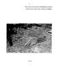
Известна, например, конструкция якоря, представляющая собой набор металлических кольев, которые забивают в грунт, связывают между собой и к ближайшему колу подсоединяют трос лебедки автомобиля (см., например, Интернет-ресурс http://www.chevy niva.ru/viewtopic.php?p=5348364). Такие якоря вряд ли работоспособны при их использовании в рыхлом грунте, поэтому не указаны в сопоставительной таблице (Фиг. 1) и не подвергались далее детальному анализу.For example, the design of the anchor is known, which is a set of metal stakes that are driven into the ground, connected together and connected to the nearest stake is the winch cable of a car (see, for example, the Internet resource http: //www.chevy niva.ru/viewtopic .php? p = 5348364). Such anchors are unlikely to work when used in loose soil, therefore, are not indicated in the comparative table (Fig. 1) and were not subjected to further detailed analysis.
В качестве плюса указанных конструкций можно отметить их простоту. Недостатком же является то, что необходимо иметь с собой кувалду для забивания кольев, а также то, что колья будут вырываться автомобилем из рыхлого грунта. Как правило, колья выполнены из стали, имеют длину 60-80 см и поэтому вся конструкция вместе с кувалдой имеет довольно значительный вес.As a plus of these designs, their simplicity can be noted. The disadvantage is that you need to have a sledgehammer with you for clogging the stakes, as well as the fact that the stakes will be pulled out of the soil by the car. As a rule, stakes are made of steel, have a length of 60-80 cm, and therefore the whole structure together with a sledgehammer has a fairly significant weight.
Устройства четвертой группы являются сложными по конструкции и могут отказать при работе в условиях грязи.The devices of the fourth group are complex in design and may fail when working in mud conditions.
Устройства пятой группы являются простейшими из известных, например -известен якорь для лебедки, представляющий собой металлическую рамку, которая прибивается к грунту шестью металлическими штырями, а к рамке цепляется трос лебедки. Такой якорь вряд ли работоспособен при использовании его в рыхлом грунте.The devices of the fifth group are the simplest known, for example, an anchor for a winch is known, which is a metal frame that is nailed to the ground with six metal pins, and the winch cable clings to the frame. Such an anchor is hardly functional when used in loose soil.
Заявленное техническое решение относится к пятой группе устройств, т.е. к наиболее простейшим устройствам самовытаскивания автомобиля. Вследствие указанного, заявителем были выполнены исследования в отношении именно наиболее простейших устройств, используемых для самовытаскивания автомобиля.The claimed technical solution relates to the fifth group of devices, i.e. to the simplest self-extracting car devices. As a result of this, the applicant carried out studies in respect of the very simplest devices used to self-extract the car.
Известен аналог [1] - самодельный винт с кольцом для вытаскивания автомобиля Виктора Воронова (см. Интернет-ресурс http://video-pro-koshak.ru/video/eHNiV19zZ082Tk0%3D, фото не представлено), представляющий собой бур, изготовленный из трубы с заостренным носом и заваренным на нем винтом из проволоки. Конструкция представляет собой самодельный винт с кольцом, находящимся в верхней части бура, вращая который посредством, например, лома, заворачивают бур в землю и затем к нему цепляют трос. Достоинства данного устройства заключается в его простоте, малом весе и возможности его изготовления даже в условиях гаража. Недостатками [1] является:A known analogue [1] is a home-made screw with a ring for pulling out a car of Victor Voronov (see Internet resource http://video-pro-koshak.ru/video/eHNiV19zZ082Tk0%3D, photo not shown), which is a drill made of pipes with a pointed nose and a wire screw welded on it. The design is a home-made screw with a ring located in the upper part of the drill, rotating which, for example, with a crowbar, wrap the drill in the ground and then hook the cable to it. The advantages of this device is its simplicity, low weight and the possibility of its manufacture, even in a garage. The disadvantages of [1] are:
1. В мягком грунте устройство неработоспособно, т.к. выдергивается из грунта.1. In soft soil, the device is inoperative, because pulled out of the ground.
2. Необходим дополнительно лом или другой подобный предмет для рычага, чтобы ввернуть винт в грунт. При этом мощность винта недостаточна для некоторых видов грунтов, т.к. при использовании требуется применение кувалды для забивания в грунт винта.2. An additional scrap or other similar item for the lever is necessary to screw the screw into the ground. At the same time, the screw power is insufficient for some types of soil, because in use, a sledgehammer is required to drive the screw into the ground.
Известен аналог [2], так называемый «Грузинский якорь» (см. Интернет-ресурс http://www.niva-faq.msk.ru/ekspluat/vne_asf/tehn_sr/lebedka/grya.htm) для лебедки, представляющий собой металлическую пластину с приваренным к ней металлическим стержнем (Фиг. 2) и его модификации. Недостатком использования данного устройства и его модификаций является то, что при работе якорь зарывается в землю и возникает дополнительная проблема извлечения якоря из грунта. По отзывам Интернет-пользователей, в рыхлом грунте даже усовершенствованный якорь необходимо протаскивать несколько раз, чтобы получить положительный результат. При этом для его использования также необходима кувалда.The analogue [2] is known, the so-called “Georgian anchor” (see the Internet resource http://www.niva-faq.msk.ru/ekspluat/vne_asf/tehn_sr/lebedka/grya.htm) for a winch, which is a metal a plate with a metal rod welded to it (Fig. 2) and its modifications. The disadvantage of using this device and its modifications is that during operation the anchor buries into the ground and there is an additional problem of extracting the anchor from the ground. According to Internet users, even an improved anchor needs to be dragged several times in loose soil to get a positive result. At the same time, a sledgehammer is also necessary for its use.
Главными недостатками описанных выше устройств по сравнению с заявленным техническим решением являются:The main disadvantages of the above devices in comparison with the claimed technical solution are:
1. Низкая эффективность работы в рыхлом грунте.1. Low work efficiency in loose soil.
2. Необходимость использования дополнительного инструмента, в частности - кувалды или лома.2. The need to use additional tools, in particular - sledgehammers or scrap.
3. Занимают много места в багажнике автомобиля.3. Take up a lot of space in the trunk of a car.
4. Появляется проблема извлечения устройства из грунта после его использования, что значительно усложняет их использование по назначению.4. There is a problem of removing the device from the soil after its use, which greatly complicates their intended use.
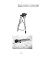
Наиболее близким техническим решением, выбранным заявителем в качестве наиболее близкого аналога (прототипа) [3], по совокупности совпадающих признаков и достигаемому техническому результату является лебедка ручная "Спутник", предназначенная для вытаскивания застрявших легковых автомобилей и других легких транспортных средств, а также для перемещения на берег из воды мотолодок и катеров (Фиг. 3) (см. Интернет-ресурс http://www.suzukovod.ru/showtread/php?t=1942).The closest technical solution chosen by the applicant as the closest analogue (prototype) [3], in terms of the combination of matching features and the technical result achieved, is the Sputnik manual winch, designed to pull out stuck cars and other light vehicles, as well as to move to the shore from the water of motor boats and boats (Fig. 3) (see. Internet resource http://www.suzukovod.ru/showtread/php?t=1942).
Сущностью известного технического решения является конструкция, состоящая из бура, ручной лебедки, рукоятки, служащей для вращения лебедки и наворачивания бура.The essence of the known technical solution is a design consisting of a drill, a manual winch, a handle that serves to rotate the winch and wind the drill.
Основными недостатками прототипа являются большие размеры и вес, т.к. в составе конструкции имеется встроенная лебедка с тросом. При этом лебедка ручная "Спутник" имеет слабую тягу, является неработоспособной в мягком грунте (сначала наклоняется и затем вытаскивается бур, а автомобиль остается в прежнем положении), имеет малую прочность троса - имеющийся тонкий трос рвется, не выдерживая нагрузки (проверено на практике на автомобиле «Нива - 2121»).The main disadvantages of the prototype are its large size and weight, because The structure of the design has a built-in winch with a cable. At the same time, the Sputnik manual winch has weak traction, is inoperative in soft soil (the drill first bends and then is pulled out, and the car remains in the same position), has a low cable strength - the existing thin cable breaks, not withstanding the load (tested in practice on car "Niva - 2121").
Заявленное техническое решение поясняется следующими иллюстрациями.The claimed technical solution is illustrated by the following illustrations.
На Фиг. 1 представлена Таблица сопоставительного анализа совпадающих признаков заявленного технического решения и аналогов для обоснования выбора заявителем наиболее близкого аналога (прототипа), где знаком «+» обозначено наличие у аналога признака, совпадающего с имеющимся у заявленного устройства, знаком «-» - отсутствие у аналога данного признака. В последнем столбце знаком «+» показано наличие отличительного признака у заявленного устройства по сравнению с суммарно взятыми признаками всех аналогов.In FIG. 1 is a table of a comparative analysis of the matching features of the claimed technical solution and analogues to substantiate the choice of the closest analogue (prototype) by the applicant, where the “+” sign indicates the presence of an analogue of the attribute that matches the one of the claimed device, the “-” sign indicates the absence of this analogue sign. In the last column, the “+” sign indicates the presence of a distinguishing feature of the claimed device in comparison with the total characteristics of all analogues.
На Фиг. 2 представлен вид (фото) аналога [1] - «Грузинский якорь».In FIG. 2 presents a view (photo) of the analogue [1] - “Georgian Anchor”.
На Фиг. 3 представлен вид (фото) прототипа [3] - ручная лебедка «Спутник».In FIG. 3 shows a view (photo) of the prototype [3] - Sputnik manual winch.
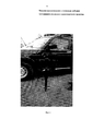
На Фиг. 4 представлено вид (фото) натурного образца - варианта исполнения заявленного технического решения.In FIG. 4 presents a view (photo) of a full-scale sample - an embodiment of the claimed technical solution.
На Фиг. 5 представлены чертежи общего вида и дополнительных видов заявленного устройства (Фиг. 5.1 - 5.5 соответственно), где 1 - бур, 2 - рукоятка, 3 - опорные лопатки, 4 - верхние полукольца, 5 - нижние полукольца, 6 - нижнее опорное кольцо, 7 - верхнее нажимное кольцо, 8 - пластина со скобой.In FIG. 5 presents drawings of a general view and additional views of the claimed device (Fig. 5.1 - 5.5, respectively), where 1 is a drill, 2 is a handle, 3 are supporting blades, 4 are upper half rings, 5 are lower half rings, 6 is the lower supporting ring, 7 - upper pressure ring, 8 - plate with bracket.
Задачей заявленного технического решения является создание автономного устройства, обладающего малым весом и простотой конструкции, которое может обеспечить эффективное вытаскивание застрявшего в раскисшем поле автомобиля с помощью лебедки и обеспечение возможности удобной эксплуатации устройства за счет особенностей конструктивного исполнения, а именно - обеспечение удобного для пользователя ввинчивания и вывинчивания бура, оснащенного опорными лопатками, входящими в грунт.The objective of the claimed technical solution is to create a stand-alone device with a low weight and simplicity of design, which can ensure the effective pulling of a vehicle stuck in a sagging field using a winch and enable convenient operation of the device due to the design features, namely, providing a screw-in that is convenient for the user and unscrewing a drill equipped with supporting blades entering the soil.
Поставленная задача решается благодаря тому, что, в отличие от ближайших аналогов, а именно, самодельного винта с кольцом для вытаскивания автомобиля Виктора Воронова, «Грузинского якоря» и лебедки ручной "Спутник", заявленное техническое решение устраняет недостатки аналогов и обеспечивает, по сравнению с ними, реализацию поставленных задач.The problem is solved due to the fact that, in contrast to the closest analogues, namely, a home-made screw with a ring for pulling out the car of Victor Voronov, the Georgian Anchor and the manual satellite winch, the claimed technical solution eliminates the disadvantages of the analogues and provides, in comparison with them, the implementation of the tasks.
Сущность заявленного технического решения заключается в том, что бур для вытаскивания с помощью лебедки застрявшего колесного транспортного средства, содержащий скобу и рукоять, размещенные в верхней части бура, и заостренный винт, находящийся в нижней части бура, характеризуется тем, что в верхней части, ниже скобы и рукояти, он оснащен опорными лопатками, размещенными посредством крепежных элементов на оси бура, с возможностью вращения опорных лопаток вокруг оси бура, при этом над опорными лопатками жестко установлено нажимное кольцо, а под опорными лопатками жестко установлено опорное кольцо, бур по п. 1 характеризуется тем, что опорные лопатки размещены параллельно продольной оси бура, с возможностью вращения вокруг оси бура, бур по п. 1 характеризуется тем, что опорные лопатки размещены «Х»-образно и условно пересекают продольную ось бура, с возможностью вращения вокруг оси бура, бур по п. 1 характеризуется тем, что опорные лопатки выполнены с возможностью монтажа и демонтажа с возможностью обеспечения удобства перевозки и эксплуатации.The essence of the claimed technical solution lies in the fact that the drill for pulling out a stuck wheeled vehicle with a winch, containing a bracket and a handle located in the upper part of the drill and a pointed screw located in the lower part of the drill, is characterized in that in the upper part, lower staples and handles, it is equipped with supporting blades placed by means of fasteners on the axis of the drill, with the possibility of rotation of the supporting blades around the axis of the drill, while a pressure ring is rigidly mounted above the supporting blades, and a support ring is rigidly mounted under the support blades, the drill according to
Более подробно, сущность заявленного технического решения заключается в том, что заявленное устройство может быть установлено пользователем без особых усилий, ввинчено в грунт за счет (например) вращения по часовой стрелке вокруг оси бура, в результате чего лопатки бура перемещаются в грунт под давлением нажимного кольца на верхнее крепежное кольцо лопатки, обеспечивая тем самым заглубление лопатки в грунт на требуемую глубину, и его (устройства) извлечение из грунта также без особых усилий, за счет воздействия опорного кольца на нижнее крепежное кольцо лопатки, исключая тем самым необходимость применения и перевозки в автомобиле дополнительных инструментов, таких как лом, кувалда, лопата.In more detail, the essence of the claimed technical solution lies in the fact that the claimed device can be installed by the user without special efforts, screwed into the ground due to (for example) rotation clockwise around the axis of the drill, as a result of which the blades of the drill move into the soil under the pressure of the pressure ring on the upper mounting ring of the scapula, thereby ensuring the depth of the scapula in the soil to the required depth, and its (device) removal from the ground also without much effort, due to the impact of the support ring on the bottom Fastening of the blade ring, thereby eliminating the need for transportation in the vehicle and additional tools, such as scrap, sledge hammer, shovel.
Заявленное устройство предназначено для работы совместно с лебедкой, которая может быть стационарно установлена на автомобиле или может крепиться к автомобилю или буру дополнительно.The claimed device is designed to work in conjunction with a winch, which can be permanently installed on the car or can be attached to the car or drill additionally.
Устройство состоит из собственно бура, с размещенными на нем соосно опорными лопатками, которые вдавливаются и выдавливаются из грунта за счет вращения бура вокруг его оси. При этом количество лопаток может быть не менее двух, при их размещении на одной оси с буром. В случае если лопаток несколько, например - более двух, они могут быть размещены «Х»-образно на одной оси с буром.The device consists of the drill itself, with coaxial supporting blades placed on it, which are pressed and squeezed out of the ground due to the rotation of the drill around its axis. Moreover, the number of blades can be at least two, when they are placed on the same axis with the drill. If there are several blades, for example, more than two, they can be placed "X" -shaped on the same axis with the drill.
Возможен вариант исполнения за счет размещения одной лопатки параллельно плоскости бура на некотором удалении от оси бура, с обеспечением возможности ее (лопатки) вращения вокруг оси бура.A variant is possible due to the placement of one blade parallel to the plane of the drill at some distance from the axis of the drill, with the possibility of its (shoulder) rotation around the axis of the drill.
В случае, представленном на Фиг. 4 (фото варианта исполнения), бур размещен посередине плоскости лопатки, симметрично к оси бура, с целью исключения его (бура) разворачивания при вытягивании автомобиля.In the case of FIG. 4 (photo of an embodiment), the drill is placed in the middle of the blade plane, symmetrically to the axis of the drill, in order to exclude it (drill) from unfolding when pulling the car.
Принципиальная схема устройства показана на Фиг. 5, на которой приведено пять эскизов (Фиг. 5.1-5.5 соответственно), раскрывающих конструкционные особенности заявленного технического решения.A schematic diagram of the device is shown in FIG. 5, which shows five sketches (Fig. 5.1-5.5, respectively), revealing the structural features of the claimed technical solution.
Устройство состоит из бура 1, рукоятки 2, двух опорных лопаток 3, двух полуколец верхних 4, двух полуколец нижних 5, кольца опорного нижнего 6, кольца верхнего нажимного 7, пластины 8 со скобой.The device consists of a
Бур для вытаскивания застрявшего автомобиля с помощью лебедки (Фиг. 5.1-5.5), представляет собой цилиндр с заостренным винтовым наконечником. В верхней части бура приварена или соединена любым другим способом пластина со скобой 8 для крепления троса лебедки и рукоятки 2 (Фиг. 5.2) для завертывания бура в грунт. Для удобства работы рукоять имеет возможность подниматься в вертикальной плоскости при вворачивании бура в грунт или опускаться при выворачивании бура из грунта, а также при складывании бура в походное положение. Для удобства работы и транспортировки рукоять можно выполнять складной или телескопической конструкции.The drill for pulling a stuck car with a winch (Fig. 5.1-5.5) is a cylinder with a pointed screw tip. In the upper part of the drill, a plate with a
Для увеличения площади опоры бур имеет две съемные опорные лопатки 3 (Фиг. 5.3), крепящиеся к верхней части цилиндра двумя полукольцами 4 и 5 (Фиг. 5.4, 5.5), с элементами крепления, служащими одновременно и ребрами жесткости для опорных лопаток.To increase the area of the support, the drill has two removable support blades 3 (Fig. 5.3), attached to the upper part of the cylinder by two
Как вариант, можно сделать одну лопатку более жесткой конструкции, просто приварив ее центральной осью площади лопатки к кольцам вокруг тела бура. В этом случае бур будет не разъемным, однако это не отразится на основной функции бура - обеспечении вытягивания автомобиля.Alternatively, one blade can be made more rigid by simply welding it with the central axis of the blade area to the rings around the drill body. In this case, the drill will not be detachable, however, this will not affect the main function of the drill - ensuring the car is pulled.
Для уменьшения сопротивления входу лопаток в грунт нижнюю кромку лопаток и полуколец с ребрами жесткости необходимо заточить. Заточка кромок лопатки может быть односторонней или двухсторонней.To reduce the resistance to the entry of the blades into the soil, the lower edge of the blades and half rings with stiffeners must be sharpened. Sharpening the edges of the blade can be one-sided or two-sided.
Лопатки имеют свободное вращение вокруг тела бура. При вворачивании бура в грунт лопатки устанавливаются пользователем в перпендикулярной плоскости к направлению вытаскивания застрявшего автомобиля.The blades have free rotation around the body of the drill. When screwing the drill into the ground, the blades are set by the user in a perpendicular plane to the direction of pulling the stuck car.
При вращении бура опорные лопатки под давлением нажимного кольца 7 вдавливаются в грунт (Фиг. 5.1). Нажимное кольцо может иметь сечение любой формы, главная его функция - обеспечить вдавливание опорных лопаток в грунт при вворачивании бура. Давление передается на верхние полукольца крепления лопаток. Нижнее опорное кольцо 6 (Фиг. 5.2) может иметь любую форму в сечении, обеспечивающую уменьшение сопротивления при входе бура в грунт, в представленном варианте сечение кольца имеет форму прямоугольного треугольника. Главная функция нижнего кольца - выдавливать опорные лопатки из грунта при выворачивании бура по окончании операции вытаскивания автомобиля, а также оказывать дополнительное сопротивление при нежелательном выдергивании бура из грунта. Та часть нижней грани опорных лопаток, которая касается рабочей поверхностью опорного кольца, не затачивается. На эту поверхность (нижнюю грань опорных лопаток) и на ответную поверхность нижних полуколец крепления давит опорное кольцо при выдвижении бура из грунта.When the drill rotates, the support blades are pressed into the ground under the pressure of the pressure ring 7 (Fig. 5.1). The pressure ring can have a cross section of any shape, its main function is to ensure that the supporting blades are pressed into the ground when the drill is screwed in. Pressure is transmitted to the upper half-rings of the blades. The lower support ring 6 (Fig. 5.2) can be of any shape in cross section, providing a decrease in resistance when the drill enters the ground, in the presented embodiment, the cross section of the ring has the shape of a rectangular triangle. The main function of the lower ring is to squeeze the support blades out of the ground when the drill is turned out at the end of the vehicle pulling operation, and also provide additional resistance if the drill is undesirably pulled out of the ground. That part of the lower edge of the support blades, which touches the working surface of the support ring, is not sharpened. On this surface (the lower face of the support blades) and on the counter surface of the lower mounting half-rings, the support ring is pressed when the drill is pulled out of the ground.
Устройство работает следующим образом.The device operates as follows.
При попадании на грунт с малой несущей способностью автомобиль погружается в грунт и нуждается в постороннем тяговом усилии для его вытаскивания для преодоления этой преграды или ухода в сторону.When hit on the ground with low bearing capacity, the car plunges into the ground and needs extraneous pulling force to pull it out to overcome this obstacle or move to the side.
Бур 1 собирают так, как показано на Фиг. 4 и Фиг. 5. Разматывают трос лебедки до места установки бура. Бур 1 устанавливают вертикально к земле, при этом опорные лопатки 3 устанавливают в перпендикулярной плоскости к направлению вытаскивания автомобиля. Кольца крепления опорных лопаток (4 и 5) имеют больший диаметр, чем наружный диаметр тела бура. Поэтому в собранном состоянии опорные лопатки вращаются вокруг оси бура. Благодаря свободному вращению опорных лопаток вокруг оси бура, они, касаясь грунта, остаются в плоскости, перпендикулярной направлению вытаскивания автомобиля при вращении бура. Бур заворачивают в грунт до полного погружения опорных лопаток 3. Лопатки 3 погружаются в грунт под давлением верхнего нажимного кольца 7 при вворачивании бура 1 в грунт. Рукоять бура 2 имеет свободу перемещения в вертикальной плоскости. Благодаря этому нет необходимости нагибаться при постепенном погружении бура 1, так как рукоять 2 при этом движении поднимается вверх, обеспечивая комфортность работы. Трос лебедки крепят к скобе 8 и включают лебедку.The
По окончании вытаскивания трос лебедки отсоединяют от автомобиля и бур 1 легко выкручивают из грунта. По мере выкручивания бура 1 и его подъема относительно земли рукоять 2 опускается вниз, при этом движении опорные лопатки 3 выдавливаются из грунта под давлением нижнего опорного кольца 6. Таким образом, бур 1 легко выходит из грунта вместе с лопатками 3.At the end of the pulling out, the winch cable is disconnected from the vehicle and the
В разобранном виде бур занимает мало места в багажнике, при этом нет необходимости отсоединять рукоять, так как она укладывается параллельно телу бура, благодаря подвижному соединению рукояти с буром. Предвидя тяжелые дорожные условия, можно собрать бур заранее. В этом случае бур также не займет много места, так как вся конструкция является плоской. /Для уменьшения веса устройства тело бура и рукояти желательно изготовить полыми. В приведенном варианте со съемными лопатками (Фиг. 4, Фиг. 5) опорные лопатки могут быть легко или демонтированы, или установлены, в зависимости от условий грунта.In disassembled form, the drill takes up little space in the trunk, while there is no need to disconnect the handle, since it fits parallel to the body of the drill, thanks to the movable connection of the handle with the drill. Anticipating difficult road conditions, you can collect the drill in advance. In this case, the drill also does not take up much space, since the entire structure is flat. / To reduce the weight of the device, it is desirable to make the body of the drill and the handle hollow. In the above embodiment with removable blades (Fig. 4, Fig. 5), the supporting blades can be easily either dismantled or installed, depending on the soil conditions.
Заявленное техническое решение может иметь различные конструкционные варианты исполнения.The claimed technical solution may have various structural options.
Так, опорные лопатки могут быть размещены параллельно продольной оси бура, с возможностью вращения вокруг оси бура.So, the supporting blades can be placed parallel to the longitudinal axis of the drill, with the possibility of rotation around the axis of the drill.
Опорные лопатки могут быть размещены «Х»-образно и условно пересекать продольную ось бура, с возможностью вращения вокруг оси бура.The supporting blades can be placed "X" -shaped and conditionally intersect the longitudinal axis of the drill, with the possibility of rotation around the axis of the drill.
Опорные лопатки могут быть выполнены с возможностью монтажа и демонтажа с возможностью обеспечения удобства перевозки и эксплуатации.The supporting blades can be made with the possibility of mounting and dismounting with the possibility of ensuring the convenience of transportation and operation.
Сопоставительный анализ заявленного технического решения с аналогами и прототипом приведен в Таблице на Фиг. 1.A comparative analysis of the claimed technical solution with analogues and prototype is shown in the Table in FIG. one.
Анализ указанной Таблицы показывает, что наиболее близким техническим решением, выбранным заявителем в качестве прототипа, является устройство «Спутник» [3], т.к. оно имеет три общих признака, отмеченных в Таблице плюсами.An analysis of this Table shows that the closest technical solution chosen by the applicant as a prototype is the "Sputnik" device [3], because it has three common features, marked in the table by pluses.
При этом следует акцентировать внимание на том, что прототип «Спутник» обеспечивает возможность легкого вворачивания и выворачивания его из грунта, однако при этом его основным недостатком является низкое сопротивление (неустойчивость в грунте) при приложении к нему тягового усилия лебедки. Аналогичный недостаток имеется и у винта Воронова [1].It should be emphasized that the Sputnik prototype provides the ability to easily screw in and out of the ground, however, its main disadvantage is the low resistance (instability in the ground) when the winch pull is applied to it. A similar disadvantage exists with the Voronov screw [1].
Аналог «Грузинский якорь» [2] характеризуется наличием опорной лопатки. При этом указанный признак, хотя и обеспечивает более высокое сопротивление воздействию лебедки (обеспечивает ее большую устойчивость в грунте), однако не препятствует зарыванию якоря довольно глубоко в грунт, что создает дополнительные проблемы при его извлечении из грунта.The analogue “Georgian Anchor” [2] is characterized by the presence of a support scapula. At the same time, this feature, although it provides higher resistance to the influence of the winch (ensures its greater stability in the ground), however, does not prevent the anchor from being buried quite deep in the ground, which creates additional problems when removing it from the ground.
Более усовершенствованный вариант «Грузинского якоря», описанный в рекламных материалах, работает следующим образом: углубляясь в грунт, разворачивается под действием усилия лебедки параллельно горизонту и скользит в грунте навстречу вытаскиваемому автомобилю, пропахивая борозду в грунте. Это требует неоднократного повторения процесса вытаскивания, что является неудобным в использовании.A more advanced version of the “Georgian Anchor”, described in the advertising materials, works as follows: going deeper into the ground, it unfolds under the influence of the winch’s efforts parallel to the horizon and slides in the ground towards the car being pulled out, plowing a furrow in the ground. This requires repeated repetition of the pulling process, which is inconvenient to use.
Заявленное техническое решение соответствует критерию «новизна», предъявляемому к изобретениям, т.к. из исследованного уровня техники не выявлено совокупности признаков, представленных в заявленной формуле изобретения.The claimed technical solution meets the criterion of "novelty" presented to the invention, because from the investigated prior art is not revealed a combination of features presented in the claimed claims.
Заявленное техническое решение имеет следующие преимущества перед аналогами и прототипом за счет устранения их недостатков, а именно - повышает устойчивость (сопротивляемость) бура к вытаскиванию из грунта при приложении вытягивающего усилия к нему, и одновременно решает задачу облегчения процесса введения и извлечения бура из грунта за счет творческого решения вопроса - в заявленном техническом решении удалось одновременно совместить в одном устройстве преимущества каждого из аналогов, при этом устранить и недостатки их свойств по отдельности, т.к. удалось одновременно усилить устойчивость бура в грунте и повысить технологичность его монтажа и демонтажа (легко вворачивается и выворачивается в грунт и из грунта). При этом устройство является несложным в изготовлении, более технологичным при эксплуатации по сравнению с аналогом «Грузинский якорь» [2], т.к. не требует многократного повторения процедуры вытаскивания автомобиля - заявленный бур не углубляется в грунт при воздействии тягового усилия лебедки, оставаясь на месте, а после вытаскивании застрявшего автомобиля легко извлекается из грунта. Таким образом, в заявленном техническом решении удалось совместить преимущества аналогов и одновременно устранить все их недостатки в одном простейшем устройстве.The claimed technical solution has the following advantages over analogues and prototype by eliminating their shortcomings, namely, it increases the stability (resistance) of the drill to pull out of the soil when applying a pulling force to it, and at the same time solves the problem of facilitating the process of introducing and removing the drill from the soil due to creative solution to the problem - in the claimed technical solution, it was possible to simultaneously combine in one device the advantages of each of the analogues, while eliminating the disadvantages of their properties by -similarity, since it was possible to simultaneously increase the stability of the drill in the ground and to increase the manufacturability of its installation and dismantling (it is easily screwed in and out of the ground and out of the ground). Moreover, the device is not difficult to manufacture, more technologically advanced during operation than the analogue of “Georgian anchor” [2], because does not require repeated repetition of the car pulling procedure - the declared drill does not go deeper into the ground when the winch pulls, remaining in place, and after pulling out a stuck car it is easily removed from the ground. Thus, in the claimed technical solution, it was possible to combine the advantages of analogues and at the same time eliminate all their disadvantages in one simple device.
Основываясь на вышеизложенном, можно сделать вывод, что заявленное техническое решение соответствует критерию «изобретательский уровень», предъявляемому к изобретениям, т.к. из известного уровня техники не выявлены технические решения, обладающие признаками, идентичными заявленным признакам формулы предполагаемого изобретения, обеспечивающие реализацию заявленных целей. При этом следует отметить достаточную оригинальность заявленного технического решения вследствие того, что заявленная совокупность признаков обеспечивает устранение недостатков, присущих как прототипу, так и другим подобным устройствам.Based on the foregoing, we can conclude that the claimed technical solution meets the criterion of "inventive step" for inventions, because from the prior art not identified technical solutions that have features identical to the claimed features of the claims of the alleged invention, ensuring the implementation of the stated goals. It should be noted that the claimed technical solution is sufficiently original due to the fact that the claimed combination of features eliminates the disadvantages inherent in both the prototype and other similar devices.
При этом также можно сделать вывод, что заявленное техническое решение не является очевидным для специалистов вследствие того, что оно (техническое решение) обеспечивает устранение приведенных заявителем в исследованном уровне техники существенных недостатков и препятствий к реализации поставленной задачи - создание устройства для вытаскивания автомобиля из грязи, обладающее преимуществами перед известными из уровня техники устройствами, для реализации указанной цели на дату подачи заявленного технического решения.It can also be concluded that the claimed technical solution is not obvious to specialists due to the fact that it (the technical solution) provides for the elimination of the significant shortcomings and obstacles to the implementation of the task given by the applicant in the studied level of technology - the creation of a device for pulling the car out of the mud, having advantages over devices known from the prior art, for the implementation of this goal on the filing date of the claimed technical solution.
Заявленное техническое решение соответствует критерию «промышленная применимость», предъявляемому к изобретениям, т.к. реализовано в условиях лаборатории сварки Елабужского института (филиала) Казанского (Приволжского) федерального университета, прошло успешную апробацию и доказало заявленные преимущества при опытной эксплуатации в полевых условиях. Например, экспериментальная апробация заявленного технического решения по вытаскиванию автомобиля «Нива» показала его удобство и, главное, эффективность в эксплуатации, т.к. в условиях бездорожья обеспечило вытаскивание из грязи не только данного автомобиля «Нива», но и других автомобилей, застрявших в грязи в полевых условиях. При этом владельцы автомобилей проявили заинтересованность либо в приобретении такого простейшего и эффективного устройства при его наличии в продаже, либо в его заказе или изготовлении для собственных нужд в частном порядке в случае наличия эскизов.The claimed technical solution meets the criterion of "industrial applicability" to the invention, because implemented in the conditions of the welding laboratory of the Elabuga Institute (branch) of the Kazan (Volga Region) Federal University, it was successfully tested and proved the declared advantages during trial operation in the field. For example, experimental testing of the claimed technical solution for pulling out a Niva car showed its convenience and, most importantly, its operational efficiency, as in off-road conditions, not only this Niva car was pulled out of the mud, but also other cars stuck in the mud in the field. At the same time, car owners showed interest either in acquiring such a simple and effective device when it is available for sale, or in ordering it or making it for their own needs privately if there are sketches.
Источники информацииInformation sources
[1] http://video-pro-koshak.ru/video/eHNiV19zZ082Tk0%3D.[1] http://video-pro-koshak.ru/video/eHNiV19zZ082Tk0%3D.
[2] http://www.niva-faq.msk.ru/ekspluat/vne_asf/tehn_sr/lebedka/gray.htm.[2] http://www.niva-faq.msk.ru/ekspluat/vne_asf/tehn_sr/lebedka/gray.htm.
[3] http://www.suzukovod.ru/showthread.php?=1942.[3] http://www.suzukovod.ru/showthread.php?=1942.
Claims (4)
Priority Applications (1)
| Application Number | Priority Date | Filing Date | Title |
|---|---|---|---|
| RU2016115979A RU2619503C1 (en) | 2016-04-22 | 2016-04-22 | Bore for stuck wheeled vehicle pulling by means of the winch |
Applications Claiming Priority (1)
| Application Number | Priority Date | Filing Date | Title |
|---|---|---|---|
| RU2016115979A RU2619503C1 (en) | 2016-04-22 | 2016-04-22 | Bore for stuck wheeled vehicle pulling by means of the winch |
Publications (1)
| Publication Number | Publication Date |
|---|---|
| RU2619503C1 true RU2619503C1 (en) | 2017-05-16 |
Family
ID=58715721
Family Applications (1)
| Application Number | Title | Priority Date | Filing Date |
|---|---|---|---|
| RU2016115979A RU2619503C1 (en) | 2016-04-22 | 2016-04-22 | Bore for stuck wheeled vehicle pulling by means of the winch |
Country Status (1)
| Country | Link |
|---|---|
| RU (1) | RU2619503C1 (en) |
Cited By (1)
| Publication number | Priority date | Publication date | Assignee | Title |
|---|---|---|---|---|
| RU2812946C1 (en) * | 2022-12-15 | 2024-02-05 | Федеральное государственное казенное образовательное учреждение высшего образования "Калининградский пограничный институт Федеральной службы безопасности Российской Федерации" | Ground anchor |
Citations (4)
| Publication number | Priority date | Publication date | Assignee | Title |
|---|---|---|---|---|
| US2096656A (en) * | 1937-03-29 | 1937-10-19 | Charles R Stoulil | Scraper for tractors |
| US4224972A (en) * | 1978-01-30 | 1980-09-30 | Granryd Thorvald G | Combination winch and traction intensifier for rubber tired vehicles |
| SU1594026A1 (en) * | 1988-06-29 | 1990-09-23 | 10-Й Автобусный Парк Отраслевого Производственного Управления Автобусного Транспорта Главного Управления Городского Пассажирского Транспорта Мосгорисполкома | Arrangement for transporting wheeled vehicle |
| RU124641U1 (en) * | 2012-09-10 | 2013-02-10 | Николай Сергеевич Крюков | MANUAL WINCH FOR VEHICLES, PREVIOUSLY CARS |
-
2016
- 2016-04-22 RU RU2016115979A patent/RU2619503C1/en active
Patent Citations (4)
| Publication number | Priority date | Publication date | Assignee | Title |
|---|---|---|---|---|
| US2096656A (en) * | 1937-03-29 | 1937-10-19 | Charles R Stoulil | Scraper for tractors |
| US4224972A (en) * | 1978-01-30 | 1980-09-30 | Granryd Thorvald G | Combination winch and traction intensifier for rubber tired vehicles |
| SU1594026A1 (en) * | 1988-06-29 | 1990-09-23 | 10-Й Автобусный Парк Отраслевого Производственного Управления Автобусного Транспорта Главного Управления Городского Пассажирского Транспорта Мосгорисполкома | Arrangement for transporting wheeled vehicle |
| RU124641U1 (en) * | 2012-09-10 | 2013-02-10 | Николай Сергеевич Крюков | MANUAL WINCH FOR VEHICLES, PREVIOUSLY CARS |
Cited By (1)
| Publication number | Priority date | Publication date | Assignee | Title |
|---|---|---|---|---|
| RU2812946C1 (en) * | 2022-12-15 | 2024-02-05 | Федеральное государственное казенное образовательное учреждение высшего образования "Калининградский пограничный институт Федеральной службы безопасности Российской Федерации" | Ground anchor |
Similar Documents
| Publication | Publication Date | Title |
|---|---|---|
| US5088681A (en) | Anchor device | |
| US20210214207A1 (en) | Multipurpose device | |
| AU2010295254B2 (en) | Post driver extractor | |
| CN205955651U (en) | Long spiral pile driver mud scrapping device of CFG stake | |
| RU2619503C1 (en) | Bore for stuck wheeled vehicle pulling by means of the winch | |
| US10927564B2 (en) | Chain and lever post puller systems | |
| CN105230185A (en) | Manual pit digger | |
| US7624545B2 (en) | Ground anchor system | |
| CN207537948U (en) | A kind of hand push clear snow multi-function vehicle | |
| CN105064785B (en) | A kind of field medical fast demountable camouflage net strut | |
| US12038026B2 (en) | Method of using a hydraulic stake puller | |
| CN2600487Y (en) | Vehicle snow remover | |
| CN203780507U (en) | Self-rescuer for trapped vehicles | |
| CN201924361U (en) | Cable traction pile extractor | |
| US20130327915A1 (en) | ShowMeStand TM | |
| CN204144645U (en) | Earth rod extracting apparatus | |
| US20180274180A1 (en) | Hydraulic Stake Puller | |
| CN105235661A (en) | Automobile tire pit-trap self-rescue method | |
| US11566393B2 (en) | Land anchor | |
| US9163371B1 (en) | Snow removal system | |
| US20040148877A1 (en) | Tie down stake | |
| CN209742495U (en) | Construction enclosure device | |
| CN208701718U (en) | Slope protection construction platform | |
| CN201924333U (en) | Self-dragging type relocation device | |
| CN115152571B (en) | Desert tree planting equipment based on water flushing method |