RU2619276C2 - Method for degassing container filled with carbonated beverage - Google Patents
Method for degassing container filled with carbonated beverage Download PDFInfo
- Publication number
- RU2619276C2 RU2619276C2 RU2014108771A RU2014108771A RU2619276C2 RU 2619276 C2 RU2619276 C2 RU 2619276C2 RU 2014108771 A RU2014108771 A RU 2014108771A RU 2014108771 A RU2014108771 A RU 2014108771A RU 2619276 C2 RU2619276 C2 RU 2619276C2
- Authority
- RU
- Russia
- Prior art keywords
- discharge head
- fluid
- sealed position
- actuator
- moving
- Prior art date
Links
Images

Classifications
-
- B—PERFORMING OPERATIONS; TRANSPORTING
- B67—OPENING, CLOSING OR CLEANING BOTTLES, JARS OR SIMILAR CONTAINERS; LIQUID HANDLING
- B67C—CLEANING, FILLING WITH LIQUIDS OR SEMILIQUIDS, OR EMPTYING, OF BOTTLES, JARS, CANS, CASKS, BARRELS, OR SIMILAR CONTAINERS, NOT OTHERWISE PROVIDED FOR; FUNNELS
- B67C3/00—Bottling liquids or semiliquids; Filling jars or cans with liquids or semiliquids using bottling or like apparatus; Filling casks or barrels with liquids or semiliquids
- B67C3/02—Bottling liquids or semiliquids; Filling jars or cans with liquids or semiliquids using bottling or like apparatus
- B67C3/22—Details
- B67C3/222—Head-space air removing devices, e.g. by inducing foam
-
- B—PERFORMING OPERATIONS; TRANSPORTING
- B65—CONVEYING; PACKING; STORING; HANDLING THIN OR FILAMENTARY MATERIAL
- B65B—MACHINES, APPARATUS OR DEVICES FOR, OR METHODS OF, PACKAGING ARTICLES OR MATERIALS; UNPACKING
- B65B3/00—Packaging plastic material, semiliquids, liquids or mixed solids and liquids, in individual containers or receptacles, e.g. bags, sacks, boxes, cartons, cans, or jars
- B65B3/02—Machines characterised by the incorporation of means for making the containers or receptacles
-
- B—PERFORMING OPERATIONS; TRANSPORTING
- B29—WORKING OF PLASTICS; WORKING OF SUBSTANCES IN A PLASTIC STATE IN GENERAL
- B29C—SHAPING OR JOINING OF PLASTICS; SHAPING OF MATERIAL IN A PLASTIC STATE, NOT OTHERWISE PROVIDED FOR; AFTER-TREATMENT OF THE SHAPED PRODUCTS, e.g. REPAIRING
- B29C49/00—Blow-moulding, i.e. blowing a preform or parison to a desired shape within a mould; Apparatus therefor
- B29C49/42—Component parts, details or accessories; Auxiliary operations
- B29C49/46—Component parts, details or accessories; Auxiliary operations characterised by using particular environment or blow fluids other than air
-
- B—PERFORMING OPERATIONS; TRANSPORTING
- B29—WORKING OF PLASTICS; WORKING OF SUBSTANCES IN A PLASTIC STATE IN GENERAL
- B29C—SHAPING OR JOINING OF PLASTICS; SHAPING OF MATERIAL IN A PLASTIC STATE, NOT OTHERWISE PROVIDED FOR; AFTER-TREATMENT OF THE SHAPED PRODUCTS, e.g. REPAIRING
- B29C49/00—Blow-moulding, i.e. blowing a preform or parison to a desired shape within a mould; Apparatus therefor
- B29C49/42—Component parts, details or accessories; Auxiliary operations
- B29C49/58—Blowing means
-
- B—PERFORMING OPERATIONS; TRANSPORTING
- B65—CONVEYING; PACKING; STORING; HANDLING THIN OR FILAMENTARY MATERIAL
- B65B—MACHINES, APPARATUS OR DEVICES FOR, OR METHODS OF, PACKAGING ARTICLES OR MATERIALS; UNPACKING
- B65B3/00—Packaging plastic material, semiliquids, liquids or mixed solids and liquids, in individual containers or receptacles, e.g. bags, sacks, boxes, cartons, cans, or jars
- B65B3/02—Machines characterised by the incorporation of means for making the containers or receptacles
- B65B3/022—Making containers by moulding of a thermoplastic material
-
- B—PERFORMING OPERATIONS; TRANSPORTING
- B65—CONVEYING; PACKING; STORING; HANDLING THIN OR FILAMENTARY MATERIAL
- B65B—MACHINES, APPARATUS OR DEVICES FOR, OR METHODS OF, PACKAGING ARTICLES OR MATERIALS; UNPACKING
- B65B3/00—Packaging plastic material, semiliquids, liquids or mixed solids and liquids, in individual containers or receptacles, e.g. bags, sacks, boxes, cartons, cans, or jars
- B65B3/22—Defoaming liquids in connection with filling
-
- B—PERFORMING OPERATIONS; TRANSPORTING
- B29—WORKING OF PLASTICS; WORKING OF SUBSTANCES IN A PLASTIC STATE IN GENERAL
- B29C—SHAPING OR JOINING OF PLASTICS; SHAPING OF MATERIAL IN A PLASTIC STATE, NOT OTHERWISE PROVIDED FOR; AFTER-TREATMENT OF THE SHAPED PRODUCTS, e.g. REPAIRING
- B29C49/00—Blow-moulding, i.e. blowing a preform or parison to a desired shape within a mould; Apparatus therefor
- B29C49/42—Component parts, details or accessories; Auxiliary operations
- B29C49/46—Component parts, details or accessories; Auxiliary operations characterised by using particular environment or blow fluids other than air
- B29C2049/4602—Blowing fluids
- B29C2049/465—Blowing fluids being incompressible
- B29C2049/4664—Blowing fluids being incompressible staying in the final article
-
- B—PERFORMING OPERATIONS; TRANSPORTING
- B29—WORKING OF PLASTICS; WORKING OF SUBSTANCES IN A PLASTIC STATE IN GENERAL
- B29C—SHAPING OR JOINING OF PLASTICS; SHAPING OF MATERIAL IN A PLASTIC STATE, NOT OTHERWISE PROVIDED FOR; AFTER-TREATMENT OF THE SHAPED PRODUCTS, e.g. REPAIRING
- B29C49/00—Blow-moulding, i.e. blowing a preform or parison to a desired shape within a mould; Apparatus therefor
- B29C49/42—Component parts, details or accessories; Auxiliary operations
- B29C49/58—Blowing means
- B29C2049/5827—Blowing means not touching the preform
-
- B—PERFORMING OPERATIONS; TRANSPORTING
- B29—WORKING OF PLASTICS; WORKING OF SUBSTANCES IN A PLASTIC STATE IN GENERAL
- B29C—SHAPING OR JOINING OF PLASTICS; SHAPING OF MATERIAL IN A PLASTIC STATE, NOT OTHERWISE PROVIDED FOR; AFTER-TREATMENT OF THE SHAPED PRODUCTS, e.g. REPAIRING
- B29C49/00—Blow-moulding, i.e. blowing a preform or parison to a desired shape within a mould; Apparatus therefor
- B29C49/42—Component parts, details or accessories; Auxiliary operations
- B29C49/58—Blowing means
- B29C2049/5862—Drive means therefore
- B29C2049/5865—Pneumatic
-
- B—PERFORMING OPERATIONS; TRANSPORTING
- B29—WORKING OF PLASTICS; WORKING OF SUBSTANCES IN A PLASTIC STATE IN GENERAL
- B29C—SHAPING OR JOINING OF PLASTICS; SHAPING OF MATERIAL IN A PLASTIC STATE, NOT OTHERWISE PROVIDED FOR; AFTER-TREATMENT OF THE SHAPED PRODUCTS, e.g. REPAIRING
- B29C49/00—Blow-moulding, i.e. blowing a preform or parison to a desired shape within a mould; Apparatus therefor
- B29C49/42—Component parts, details or accessories; Auxiliary operations
- B29C49/58—Blowing means
- B29C2049/5862—Drive means therefore
- B29C2049/5868—Hydraulic
-
- B—PERFORMING OPERATIONS; TRANSPORTING
- B29—WORKING OF PLASTICS; WORKING OF SUBSTANCES IN A PLASTIC STATE IN GENERAL
- B29C—SHAPING OR JOINING OF PLASTICS; SHAPING OF MATERIAL IN A PLASTIC STATE, NOT OTHERWISE PROVIDED FOR; AFTER-TREATMENT OF THE SHAPED PRODUCTS, e.g. REPAIRING
- B29C2949/00—Indexing scheme relating to blow-moulding
- B29C2949/07—Preforms or parisons characterised by their configuration
- B29C2949/0715—Preforms or parisons characterised by their configuration the preform having one end closed
-
- B—PERFORMING OPERATIONS; TRANSPORTING
- B29—WORKING OF PLASTICS; WORKING OF SUBSTANCES IN A PLASTIC STATE IN GENERAL
- B29C—SHAPING OR JOINING OF PLASTICS; SHAPING OF MATERIAL IN A PLASTIC STATE, NOT OTHERWISE PROVIDED FOR; AFTER-TREATMENT OF THE SHAPED PRODUCTS, e.g. REPAIRING
- B29C49/00—Blow-moulding, i.e. blowing a preform or parison to a desired shape within a mould; Apparatus therefor
- B29C49/02—Combined blow-moulding and manufacture of the preform or the parison
- B29C49/06—Injection blow-moulding
-
- B—PERFORMING OPERATIONS; TRANSPORTING
- B29—WORKING OF PLASTICS; WORKING OF SUBSTANCES IN A PLASTIC STATE IN GENERAL
- B29L—INDEXING SCHEME ASSOCIATED WITH SUBCLASS B29C, RELATING TO PARTICULAR ARTICLES
- B29L2031/00—Other particular articles
- B29L2031/712—Containers; Packaging elements or accessories, Packages
- B29L2031/7158—Bottles
-
- B—PERFORMING OPERATIONS; TRANSPORTING
- B67—OPENING, CLOSING OR CLEANING BOTTLES, JARS OR SIMILAR CONTAINERS; LIQUID HANDLING
- B67C—CLEANING, FILLING WITH LIQUIDS OR SEMILIQUIDS, OR EMPTYING, OF BOTTLES, JARS, CANS, CASKS, BARRELS, OR SIMILAR CONTAINERS, NOT OTHERWISE PROVIDED FOR; FUNNELS
- B67C3/00—Bottling liquids or semiliquids; Filling jars or cans with liquids or semiliquids using bottling or like apparatus; Filling casks or barrels with liquids or semiliquids
- B67C3/02—Bottling liquids or semiliquids; Filling jars or cans with liquids or semiliquids using bottling or like apparatus
- B67C3/22—Details
- B67C2003/227—Additional apparatus related to blow-moulding of the containers, e.g. a complete production line forming filled containers from preforms
Abstract
Description
Область техники, к которой относится изобретениеFIELD OF THE INVENTION
Настоящее изобретение относится к способу дегазирования контейнера, наполненного газированным напитком, в устройстве для выдувки и наполнения контейнеров и к соответствующему устройству.The present invention relates to a method for degassing a container filled with carbonated drink in a device for blowing and filling containers and to a corresponding device.
Уровень техникиState of the art
Пластиковые контейнеры, например, бутылки для воды, изготавливаются и наполняются различными способами, включая сюда формование с раздувом или ориентированное формование раздувом.Plastic containers, such as water bottles, are made and filled in various ways, including here blow molding or oriented blow molding.
По одному из этих известных способов сначала изготавливается пластиковая преформа с помощью процесса формования, которая затем нагревается перед размещением внутри формы.In one of these known methods, a plastic preform is first made using a molding process, which is then heated before being placed inside the mold.
Преформа обычно имеет форму цилиндрической трубы, закрытой на нижнем конце и открытой на противоположном конце.The preform is usually in the form of a cylindrical pipe, closed at the lower end and open at the opposite end.
После размещения преформы в форме будет виден только ее открытый конец, выступающий из формы.After placing the preform in the mold, only its open end protruding from the mold will be visible.
По этому способу используется вытягивающий стержень, который вводится в нижнем направлении в открытый конец преформы и входит в контакт с закрытым нижним концом преформы. Затем вытягивающий стержень перемещается дальше и толкает закрытый конец вниз, вытягивая преформу.According to this method, a pulling rod is used, which is introduced in the lower direction into the open end of the preform and comes into contact with the closed lower end of the preform. Then the pull rod moves further and pushes the closed end down, pulling the preform.
После начала этапа вытягивания жидкость также нагнетается в преформу через ее открытый конец. Нагнетание жидкости вызывает расширение преформы до тех пор, пока не будет достигнут контакт с внутренними стенками формы, в результате чего бутылка приобретает окончательную форму.After the start of the drawing step, the fluid is also pumped into the preform through its open end. The injection of liquid causes the preform to expand until contact with the inner walls of the mold is achieved, with the result that the bottle takes on its final shape.
Когда жидкость, нагнетаемая в преформу, содержит растворенный газ, например, газированная вода или любой другой газированный напиток, газ должен быть выпущен из отверстия бутылки в атмосферу, прежде чем отверстие будет закрыто крышкой.When the fluid injected into the preform contains dissolved gas, such as carbonated water or any other carbonated drink, the gas must be released from the opening of the bottle into the atmosphere before the opening is closed by a cap.
В настоящее время выпуск газа в атмосферу выполняется посредством открывания сообщающегося канала между отверстием бутылки и наружной атмосферой.Currently, gas is released into the atmosphere by opening a communicating channel between the bottle opening and the outside atmosphere.
Однако существует необходимость в улучшенном способе, который обеспечивает дегазирование или выпуск газа в атмосферу из контейнера, наполненного газированным напитком.However, there is a need for an improved method that degasses or releases gas into the atmosphere from a container filled with a carbonated beverage.
Раскрытие изобретенияDisclosure of invention
В этом отношении изобретение предлагает способ, определенный в п. 1 формулы изобретения.In this regard, the invention provides a method as defined in
Этот способ позволяет выполнять дегазирование газированного напитка в контейнере за счет соответствующих перемещений нагнетательной головки относительно открытого контейнера. Последовательные перемещения нагнетательной головки обеспечивают управляемое и поэтапное сообщение внутренней стороны контейнера с атмосферой. Другими словами, этот способ обеспечивает эффективный выпуск газа из разливного отверстия контейнера в атмосферу. Таким образом, эти перемещения нагнетательной головки по продольной оси вызывают планомерное и эффективное дегазирование газированного напитка.This method allows the degassing of a carbonated beverage in the container due to appropriate movements of the discharge head relative to the open container. Sequential movements of the discharge head provide a controlled and phased communication of the inner side of the container with the atmosphere. In other words, this method provides an efficient release of gas from a container outlet into the atmosphere. Thus, these displacements of the discharge head along the longitudinal axis cause a systematic and effective degassing of the carbonated drink.
Следует отметить, что назначение этого способа не состоит в том, чтобы полностью удалить газ из контейнера, хотя способ и был квалифицирован как способ дегазирования.It should be noted that the purpose of this method is not to completely remove gas from the container, although the method was qualified as a degassing method.
В частности, первый этап инициирует процесс выпуска газа и обеспечивает первый управляемый частичный выпуск газа в атмосферу из наполненного контейнера. Затем выполняется возвратное перемещение нагнетательной головки во избежание вспенивания и расплескивания. Следует отметить, что во время первого этапа нагнетательная головка может перемещаться из герметичного положения быстрее, чем по существующему уровню техники благодаря вышеуказанному последующему возвратному перемещению. После возврата нагнетательной головки в герметичное положение она удерживается в этом положении в течение заданного периода времени. Этот этап или фаза удерживания позволяет избежать вспенивания и расплескивания, поскольку обеспечивается стабилизация процесса выпуска газа. В ходе последнего этапа (этап iii)) процесс выпуска газа выполняется управляемым образом, и нагнетательная головка перемещается из герметичного положения в негерметичное положение, в котором обеспечивается выпуск газа из контейнера в атмосферу. Скорость нагнетательной головки и продолжительность этапов в значительной степени зависят от газированного напитка (скорости газирования и т.д.).In particular, the first stage initiates the gas release process and provides the first controlled partial release of gas into the atmosphere from the filled container. Then the discharge head is moved back to prevent foaming and splashing. It should be noted that during the first stage, the discharge head can move from the sealed position faster than in the prior art due to the aforementioned subsequent return movement. After the discharge head is returned to the sealed position, it is held in this position for a predetermined period of time. This holding phase or phase avoids foaming and splashing, since stabilization of the gas discharge process is ensured. In the last step (step iii)), the gas discharge process is carried out in a controlled manner, and the discharge head is moved from the sealed position to the untight position, in which the gas is released from the container into the atmosphere. The speed of the discharge head and the duration of the steps are largely dependent on the carbonated beverage (carbonation rate, etc.).
В общем, нагнетательная головка размещается над формой, и открытым контейнером и выровнена с формой и контейнером по вертикальной оси или оси, которая наклонена относительно вертикальной оси под углом меньше 90°.In general, the discharge head is positioned above the mold and the open container and aligned with the mold and container along a vertical axis or axis that is inclined relative to the vertical axis at an angle of less than 90 °.
Перемещения нагнетательной головки, в общем, именуются как перемещения вверх и вниз.Displacement of the discharge head is generally referred to as up and down movements.
По возможной отличительной характеристике способ содержит этап iv) дальнейшего перемещения нагнетательной головки из герметичного положения в более удаленное негерметичное положение и с более высокой скоростью по сравнению с этапом iii).According to a possible distinguishing characteristic, the method comprises step iv) further moving the discharge head from the sealed position to a more distant non-sealed position and at a higher speed compared to step iii).
Этот следующий этап позволяет получить короткое время цикла.This next step allows you to get a short cycle time.
По возможной отличительной характеристике на этапе i) нагнетательная головка перемещается в первое негерметичное положение.According to a possible distinguishing characteristic, in step i), the discharge head moves to the first leaky position.
По возможной отличительной характеристике негерметичное положение предусмотрено на коротком расстоянии от герметичного положения.According to a possible distinguishing characteristic, an untight position is provided at a short distance from the tight position.
Это небольшое смещение нагнетательной головки создает незначительный зазор между нагнетательной головкой и поверхностью контейнера (например, разливным отверстием), с которым нагнетательная головка находилась в плотном контакте перед этим перемещением.This slight displacement of the discharge head creates a slight gap between the discharge head and the surface of the container (for example, a tapping hole) with which the discharge head was in close contact before this movement.
Незначительный зазор позволяет установить взаимодействие между пространством вокруг и внутри разливного отверстия и наружной атмосферой.A slight clearance allows the interaction between the space around and inside the tapping hole and the outside atmosphere to be established.
Это обеспечивает планомерный предварительный выпуск газа в атмосферу вместо первого слишком большого смещения. Величина зазора или расстояния зависит от скорости нагнетательной головки, когда она движется из герметичного положения, и продолжительности перемещения.This provides a systematic preliminary release of gas into the atmosphere instead of the first too large displacement. The amount of clearance or distance depends on the speed of the discharge head as it moves from its sealed position and the duration of the movement.
Также следует отметить, что это первое перемещение из герметичного положения в первое негерметичное положение выполняется медленно, так чтобы обеспечить незначительный зазор.It should also be noted that this first movement from the sealed position to the first non-sealed position is slow so as to provide a slight clearance.
Этот первый этап обеспечивает медленное дегазирование газированного напитка, что исключает вспенивание и расплескивание.This first step provides a slow degassing of the carbonated beverage, which eliminates foaming and spilling.
Скорость первого перемещения нагнетательной головки из герметичного положения должна выбираться в зависимости от скорости газирования напитка. Чем выше скорость газирования, тем медленнее должно быть перемещение.The speed of the first movement of the discharge head from the sealed position should be selected depending on the rate of carbonation of the drink. The higher the aeration rate, the slower the movement should be.
Максимальная скорость, которая должна выбираться независимо от скорости газирования, является скоростью, при которой можно удерживать напиток в контейнере, обеспечивая при этом как можно более короткое время цикла.The maximum speed that should be selected regardless of the aeration rate is the speed at which the beverage can be held in the container, while providing the shortest possible cycle time.
По другой отличительной характеристике на этапе iii) нагнетательная головка перемещается во второе негерметичное положение, предусмотренное дальше первого негерметичного положения от герметичного положения.According to another distinguishing characteristic in step iii), the discharge head is moved to a second non-tight position provided farther from the first non-tight position from the sealed position.
После перемещения нагнетательной головки на этапе i) из герметичного положения в первое негерметичное положение уже выполняется предварительный выпуск газа в атмосферу. Это позволяет на этапе ii) перемещать нагнетательную головку дальше первого негерметичного положения из герметичного положения без вспенивания и расплескивания.After the discharge head has been moved in step i) from the sealed position to the first non-sealed position, gas is already preliminarily released into the atmosphere. This allows, in step ii), to move the discharge head beyond the first leaky position from the sealed position without foaming and splashing.
По другой возможной отличительной характеристике на этапе iv) нагнетательная головка перемещается в третье негерметичное положение, предусмотренное дальше второго негерметичного положения от герметичного положения.According to another possible distinguishing characteristic, in step iv), the discharge head is moved to a third unsealed position provided farther from the second unsealed position from the sealed position.
Благодаря поэтапному выпуску газа в атмосферу во время процесса может быть достигнуто третье негерметичное положение нагнетательной головки.Due to the phased release of gas into the atmosphere during the process, a third leaky position of the discharge head can be achieved.
По возможной отличительной характеристике на этапе i) нагнетательная головка перемещается в течение первого периода времени.According to a possible distinguishing characteristic, in step i), the discharge head moves during the first time period.
По другой возможной отличительной характеристике на этапе и) нагнетательная головка перемещается назад в течение второго периода времени, который является более коротким по сравнению с первым периодом времени.According to another possible distinguishing characteristic in step i), the discharge head moves backward during the second time period, which is shorter than the first time period.
По возможной отличительной характеристике на этапе iii) нагнетательная головка перемещается в течение третьего периода времени, который превышает первый период времени.According to a possible distinguishing characteristic in step iii), the discharge head moves during the third time period, which exceeds the first time period.
Это перемещение из герметичного положения продолжается дольше первого перемещения в первое негерметичное положение и выполняется с такой же скоростью.This movement from the sealed position lasts longer than the first movement to the first leaking position and is performed at the same speed.
Это обеспечивает более удаленное негерметичное положение, которое должно быть достигнуто во время поэтапного выпуска газа из разливного отверстия контейнера в атмосферу.This provides a more distant non-leaking position, which should be achieved during the phased release of gas from the filling opening of the container into the atmosphere.
Это медленное и более продолжительное перемещение также способствует исключению вспенивания и расплескивания.This slower and longer movement also helps to prevent foaming and splashing.
Следует отметить, что в других вариантах выполнения этап iii) необязательно должен продолжаться дольше этапа i), и второе негерметичное положение может соответствовать или не соответствовать первому негерметичному положению.It should be noted that in other embodiments, step iii) does not have to last longer than step i), and the second leaky position may or may not correspond to the first leaky position.
По возможной отличительной характеристике способ содержит этап управления перемещениями нагнетательной головки по продольной оси. Благодаря управлению перемещениями нагнетательной головки по продольной оси имеется возможность перемещать нагнетательную головку точно и эффективно для достижения требуемого результата.According to a possible distinguishing characteristic, the method comprises the step of controlling the displacements of the discharge head along the longitudinal axis. By controlling the movement of the discharge head along the longitudinal axis, it is possible to move the discharge head accurately and efficiently to achieve the desired result.
По возможной отличительной характеристике способ содержит этап управления, по меньшей мере, одним исполнительным механизмом, приведение в действие которого вынуждает нагнетательную головку перемещаться надлежащим образом. В частности, перемещения нагнетательной головки управляются за счет управления, по меньшей мере, одним исполнительным механизмом, который вызывает приведение в действие нагнетательной головки.According to a possible distinguishing characteristic, the method comprises the step of controlling at least one actuator, the actuation of which forces the discharge head to move properly. In particular, the displacements of the discharge head are controlled by controlling at least one actuator that causes the discharge head to be actuated.
К примеру, по меньшей мере, один исполнительный механизм является исполнительным механизмом с приводом от текучей среды, который приводит в действие нагнетательную головку.For example, at least one actuator is a fluid driven actuator that drives a discharge head.
Эта текучая среда может быть воздухом или жидкостью, например, маслом или водой.This fluid may be air or liquid, for example, oil or water.
Следует отметить, что могут быть предусмотрены исполнительные механизмы других типов. Например, исполнительные механизмы с электроприводом.It should be noted that other types of actuators may be provided. For example, actuators with electric drive.
По возможной отличительной характеристике этап управления исполнительным механизмом с приводом от текучей среды содержит подэтап управления подачей текучей среды к исполнительному механизму с приводом от текучей среды.According to a possible distinctive characteristic, the step of controlling the actuator driven by a fluid comprises a sub-step for controlling the flow of fluid to the actuator driven by a fluid.
По возможной отличительной характеристике подэтап управления подачей текучей среды к исполнительному механизму с приводом от текучей среды содержит управление главным клапаном и вспомогательным клапаном.According to a possible distinctive characteristic, the fluid control sub-step to the fluid driven actuator comprises controlling a main valve and an auxiliary valve.
Благодаря управлению рабочим состоянием главного клапана и вспомогательного клапана, т.е. их открытым и закрытым состояниями, имеется возможность управлять подачей текучей среды к исполнительному механизму с приводом от текучей среды и перемещением, которое должно обеспечиваться с помощью нагнетательной головки.By controlling the operating state of the main valve and auxiliary valve, i.e. their open and closed states, it is possible to control the flow of fluid to the actuator driven by the fluid and the movement, which should be provided using the discharge head.
По возможной отличительной характеристике этапы i) и ii) выполняются посредством управления подачей текучей среды к исполнительному механизму с гидравлическим или пневматическим приводом с помощью главного клапана.According to a possible distinguishing characteristic, steps i) and ii) are performed by controlling the flow of fluid to the hydraulic or pneumatic actuator using the main valve.
Главный клапан обеспечивает выполнение этапов i)-iii).The main valve provides steps i) -iii).
Например, эти этапы соответственно выполняются посредством закрывания, открывания и закрывания главного клапана.For example, these steps are respectively performed by closing, opening and closing the main valve.
Однако следует отметить, что эти этапы могут альтернативно выполняться за счет функционирования главного клапана иным образом и, к примеру, за счет последовательного открывания, закрывания и открывания главного клапана.However, it should be noted that these steps can alternatively be performed due to the functioning of the main valve in a different way and, for example, due to the successive opening, closing and opening of the main valve.
По возможной отличительной характеристике этап iv) выполняется посредством управления подачей текучей среды к исполнительному механизму с приводом от текучей среды через вспомогательный клапан.According to a possible distinguishing characteristic, step iv) is performed by controlling the flow of fluid to the actuator driven by the fluid through an auxiliary valve.
Вспомогательный клапан обеспечивает выполнение этапа iv). Однако следует отметить, что этап iv) выполняется при одновременном управлении подачей текучей среды к исполнительному механизму с приводом от текучей среды через главный клапан.The auxiliary valve provides step iv). However, it should be noted that step iv) is performed while controlling the flow of fluid to the actuator driven by the fluid through the main valve.
Таким образом, во время этапа iv) вспомогательный клапан функционирует вместе с главным клапаном для достижения требуемого результата, т.е. ускорения перемещения нагнетательной головки из герметичного положения.Thus, during step iv), the auxiliary valve functions together with the main valve to achieve the desired result, i.e. accelerating the displacement of the discharge head from the sealed position.
Например, вспомогательный клапан открывается для выполнения этапа iv).For example, an auxiliary valve is opened to perform step iv).
Однако вспомогательный клапан может, как вариант, функционировать иначе для достижения такого же результата. Например, он может быть закрыт.However, the auxiliary valve may alternatively function differently to achieve the same result. For example, it may be closed.
Конструкция или компоновка системы циркуляции текучей среды, содержащей главный клапан и вспомогательный клапан, соединенные, по меньшей мере, с одним исполнительным механизмом с гидравлическим или пневматическим приводом, могут варьироваться.The design or layout of a fluid circulation system comprising a main valve and an auxiliary valve connected to at least one actuator with a hydraulic or pneumatic actuator may vary.
В частности, конструкция может варьироваться, если перемещение нагнетательной головки из герметичного положения управляется посредством открывания главного клапана или его закрывания.In particular, the design may vary if the movement of the discharge head from the sealed position is controlled by opening or closing the main valve.
То же самое относится к вспомогательному клапану.The same applies to the auxiliary valve.
По изобретению также предлагается устройство для выдувки и наполнения контейнера, содержащее:The invention also provides a device for blowing and filling a container, comprising:
- форму, окружающую выдутый контейнер, который наполнен газированным напитком и имеет разливное отверстие;- a mold surrounding an inflated container that is filled with a carbonated drink and has a pouring opening;
- нагнетательную головку, выполненную с возможностью перемещения по продольной оси, проходящей через разливное отверстие контейнера, между герметичным положением, в котором нагнетательная головка находится в плотном контакте с разливным отверстием, и негерметичным положением, в котором нагнетательная головка находится на расстоянии от разливного отверстия;- a discharge head adapted to be moved along a longitudinal axis passing through the tapping opening of the container between a sealed position in which the discharge head is in tight contact with the tapping hole and an untight position in which the discharge head is at a distance from the tapping hole;
- средства перемещения нагнетательной головки,- means for moving the discharge head,
отличающееся тем, что средства перемещения нагнетательной головки пригодны для выполнения следующих этапов:characterized in that the means for moving the discharge head are suitable for performing the following steps:
i) перемещение нагнетательной головки из герметичного положения в негерметичное положение;i) moving the discharge head from the sealed position to the non-sealed position;
ii) перемещение нагнетательной головки в обратном направлении в герметичное положение;ii) moving the discharge head in the opposite direction to the sealed position;
iii) перемещение нагнетательной головки из герметичного положения в негерметичное положение.iii) moving the discharge head from the sealed position to the non-sealed position.
Вышеуказанное устройство пригодно для выполнения этапов способа по п. 1 формулы изобретения весьма простым образом.The above device is suitable for performing the steps of the method according to
Способ является преимущественным в том отношении, что его внедрение не требует значительных модификаций стандартного устройства для выдувки и наполнения контейнеров.The method is advantageous in that its implementation does not require significant modifications of the standard device for blowing and filling containers.
Следует отметить, что этот процесс поэтапного дегазирования, в целом, является более коротким по времени по сравнению с одним непрерывным перемещением нагнетательной головки из герметичного положения.It should be noted that this phased degassing process is generally shorter in time compared to one continuous movement of the discharge head from the sealed position.
Это было достигнуто благодаря двухэтапному перемещению нагнетательной головки из герметичного положения, при этом указанные два этапа отделены друг от друга возвратным перемещением в герметичное положение.This was achieved due to a two-stage movement of the discharge head from the sealed position, while these two stages are separated from each other by returning to the sealed position.
Как указано выше в отношении способа, средства перемещения нагнетательной головки также пригодны для удерживания нагнетательной головки в герметичном положении в течение заданного периода времени.As indicated above with respect to the method, the means for moving the discharge head are also suitable for holding the discharge head in a sealed position for a predetermined period of time.
По возможной отличительной характеристике средства перемещения нагнетательной головки пригодны для выполнения этапа iv) дальнейшего перемещения нагнетательной головки из герметичного положения в более удаленное негерметичное положение и с более высокой скоростью по сравнению с этапом iii).According to a possible distinguishing characteristic, the means for moving the discharge head are suitable for performing step iv) of further moving the discharge head from the sealed position to a more distant non-sealed position and at a higher speed compared to step iii).
По возможной отличительной характеристике устройство содержит средства для управления средствами перемещения нагнетательной головки и воздействия на нагнетательную головку с целью ее перемещения, как определено в отношении этапов i) -iii), а также этапа iv), там, где необходимо.According to a possible distinctive characteristic, the device comprises means for controlling means for moving the discharge head and acting on the discharge head to move it, as defined in relation to steps i) -iii), as well as step iv), where necessary.
Таким образом, средства перемещения нагнетательной головки пригодны для выполнения этапов способа с помощью соответствующего управления этими средствами.Thus, the means for moving the discharge head are suitable for carrying out the steps of the method by appropriately controlling these means.
По возможной отличительной характеристике средства перемещения нагнетательной головки содержат, по меньшей мере, один исполнительный механизм.According to a possible distinguishing characteristic, the means for moving the discharge head contain at least one actuator.
Например, по меньшей мере, один исполнительный механизм является исполнительным механизмом с приводом от текучей среды.For example, at least one actuator is a fluid driven actuator.
По возможной отличительной характеристике средства управления исполнительным механизмом с приводом от текучей среды содержат средства управления подачей текучей среды к исполнительному механизму с приводом от текучей среды.According to a possible distinguishing characteristic, the means for controlling the actuator driven by the fluid comprise means for controlling the flow of fluid to the actuator driven by the fluid.
Исполнительный механизм с приводом от текучей среды управляется посредством управления подачей текучей среды.The fluid driven actuator is controlled by controlling the flow of fluid.
В частности, средства управления подачей текучей среды к исполнительному механизму с приводом от текучей среды содержат главный клапан и вспомогательный клапан.In particular, fluid control means for a fluid driven actuator comprise a main valve and an auxiliary valve.
Таким образом, система циркуляции текучей среды, содержащая главный клапан и вспомогательный клапан, соединена надлежащим образом с исполнительным механизмом с приводом от текучей среды, так чтобы обеспечивать надлежащее управление подачей текучей среды и обеспечивать соответствующее перемещение нагнетательной головки.Thus, a fluid circulation system comprising a main valve and an auxiliary valve is appropriately connected to a fluid driven actuator so as to provide proper control of the fluid supply and to ensure proper movement of the discharge head.
По возможной отличительной характеристике главный клапан пригоден для подачи текучей среды к исполнительному механизму с приводом от текучей среды, с целью обеспечения перемещения нагнетательной головки, как определено в отношении этапов i)-iii).According to a possible distinguishing characteristic, the main valve is suitable for supplying fluid to the actuator driven by the fluid, in order to ensure the displacement of the discharge head, as defined in relation to steps i) to iii).
Следует отметить, что главный клапан приводится в действие по-разному для выполнения перемещения из герметичного положения и возвратного перемещения, как соответственно определено в отношении этапов i) и ii).It should be noted that the main valve is actuated in different ways to perform movement from the sealed position and return movement, as determined respectively in relation to steps i) and ii).
По возможной отличительной характеристике вспомогательный клапан пригоден для подачи текучей среды к исполнительному механизму с приводом от текучей среды с целью обеспечения перемещения нагнетательной головки, как определено в отношении этапа iv).According to a possible distinguishing characteristic, the auxiliary valve is suitable for supplying fluid to the actuator driven by a fluid in order to ensure movement of the discharge head, as determined in relation to step iv).
Вспомогательный клапан пригоден совместно с главным клапаном для перемещения нагнетательной головки, как определено в отношении этапа iv).The auxiliary valve is suitable in conjunction with the main valve to move the discharge head, as determined in relation to step iv).
По возможной отличительной характеристике средства управления подачей текучей среды к исполнительному механизму с приводом от текучей среды содержат регулятор расхода для уменьшения расхода текучей среды, поступающей к исполнительному механизму с приводом от текучей среды с целью медленного перемещения нагнетательной головки из герметичного положения в негерметичное положение.According to a possible distinctive characteristic, the means for controlling the flow of fluid to the actuator driven by the fluid contain a flow regulator to reduce the flow of fluid entering the actuator driven by the fluid in order to slowly move the discharge head from the sealed position to the non-tight position.
Этот регулятор расхода обеспечивает замедление перемещения нагнетательной головки из герметичного положения.This flow regulator slows down the discharge head from its sealed position.
Это обеспечивает улучшенное управление перемещением нагнетательной головки.This provides improved control of the displacement of the discharge head.
Краткое описание чертежейBrief Description of the Drawings
Ниже только в качестве примера приводится описание вариантов выполнения настоящего изобретения со ссылкой на приложенные чертежи.The following describes, by way of example only, embodiments of the present invention with reference to the attached drawings.
На фиг. 1 показан схематичный и частичный вид устройства для выдувки и наполнения контейнера;In FIG. 1 shows a schematic and partial view of a device for blowing and filling a container;
на фиг. 2A - схематичный вид системы циркуляции текучей среды для управления перемещением из герметичного положения и возвратным перемещением нагнетательной головки;in FIG. 2A is a schematic view of a fluid circulation system for controlling movement from a sealed position and return movement of a discharge head;
на фиг. 2B-E - последовательные схематичные виды, аналогичные виду из фиг. 2A, на которых показано течение текучей среды в системе циркуляции текучей среды для обеспечения различных положений нагнетательной головки в ходе выполнения способа по изобретению;in FIG. 2B-E are sequential schematic views similar to that of FIG. 2A showing the flow of a fluid in a fluid circulation system to provide different positions of the discharge head during the execution of the method of the invention;
на фиг. 3A-D - последовательные схематичные виды, аналогичные виду из фиг. 1, на которых показаны различные положения нагнетательной головки в ходе выполнения способа по изобретению;in FIG. 3A-D are sequential schematic views similar to that of FIG. 1, which shows the different positions of the discharge head during the execution of the method according to the invention;
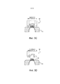
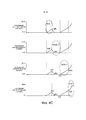
на фиг. 4A-C - временные диаграммы, на которых показаны, соответственно, различные состояния (открытые или закрытые) главного и вспомогательного клапанов системы из фиг. 2A-E и соответствующие положения нагнетательной головки.in FIG. 4A-C are timing diagrams, respectively, showing various states (open or closed) of the main and auxiliary valves of the system of FIG. 2A-E and corresponding positions of the discharge head.
Осуществление изобретенияThe implementation of the invention
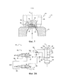
На фиг. 1 показан схематичный частичный вид основных компонентов устройства 10 для выдувки и наполнения контейнера.In FIG. 1 shows a schematic partial view of the main components of a
Устройства 10 содержит форму 12, в которую помещен контейнер 14, например, бутылка.The
Бутылка, которая была изготовлена формованием с раздувом или ориентированным формованием раздувом, содержит разливное отверстие 16, имеющее горлышко 18 с наружной резьбой и фланец или кольцо 20 горлышка, которое расположено у основания горлышка.A bottle that has been blown or oriented blow molded comprises a tapping
Контейнер был сформован таким образом, чтобы разливное отверстие 16 выступало из формы 12 и находилось выше формы.The container was molded so that the tapping
В частности, кольцо 20 горлышка опирается на заплечик 22, предусмотренный в верхней части формы вокруг контейнера 14.In particular, the
Устройство 10 также содержит нагнетательную головку 24, которая входит в контакт с верхней поверхностью формы 12 или контейнера 14 на кольце 20 горлышка в процессе выполнения способа выдувки и наполнения.The
Нагнетательная головка 24 содержит нагнетательный клапан 26, предусмотренный во внутреннем корпусе 28.The
Нагнетательная головка 24, по существу, имеет цилиндрическую форму, как частично показано на фиг. 1, и внутренний корпус 28 также имеет цилиндрическую форму, причем они оба расположены концентрично. После выдувки и наполнения контейнера 14 жидкостью, нагнетательный клапан 26 находится в нижнем положении, как показано на фиг. 1, в плотном контакте с внутренней поверхностью 28a корпуса 28, препятствуя дальнейшему течению жидкости в контейнер 14 и обеспечивая герметичное для жидкости соединение.The
Как показано на фиг. 1, продольная ось A, которая совпадает с вертикальной осью, проходит по центру разливного отверстия 16.As shown in FIG. 1, the longitudinal axis A, which coincides with the vertical axis, extends through the center of the
Нагнетательная головка 24 и форма 12, по существу, выровнены по продольной оси A.The
Следует отметить, что ось A является осью симметрии контейнера 14.It should be noted that the axis A is the axis of symmetry of the
В настоящем изобретении контейнер 14 был заполнен жидкостью, содержащей растворенный газ, например, газированной водой или, в общем, газированным напитком любого вида.In the present invention, the
В этом варианте выполнения контейнер 14 является пластиковым контейнером, изготовленным известным способом, например, описанным в документе EP 1529620 B1.In this embodiment, the
Согласно этому способу пластиковая преформа сначала изготавливается посредством формования и затем нагревается перед размещением в форме 12.According to this method, a plastic preform is first made by molding and then heated before being placed in
Форма 12 может быть разделена на несколько частей в зависимости от процесса изготовления.
Преформа обычно имеет форму цилиндрической трубы, закрытой на нижнем конце и открытой на противоположном конце.The preform is usually in the form of a cylindrical pipe, closed at the lower end and open at the opposite end.
После размещения преформы в форме будет виден только ее открытый конец, выступающий из формы.After placing the preform in the mold, only its open end protruding from the mold will be visible.
Открытый конец профилируется во время процесса, в результате которого образуется разливное отверстие 16.The open end is profiled during the process, which results in the formation of a tapping
Во время процесса выдувки и наполнения используется вытягивающий стержень (не показан на чертеже), который вводится в нижнем направлении в открытый конец преформы и входит в контакт с закрытым нижним концом преформы. Затем вытягивающий стержень перемещается дальше и толкает закрытый конец вниз, вытягивая преформу регулируемым образом.During the blowing and filling process, a pulling rod (not shown) is used, which is introduced downwardly into the open end of the preform and comes into contact with the closed lower end of the preform. Then, the pull rod moves further and pushes the closed end down, pulling the preform in an adjustable manner.
После начала этапа вытягивания вышеупомянутая жидкость нагнетается в преформу через открытый конец вокруг вытягивающего стержня, при этом последний продолжает перемещаться.After the start of the drawing step, the aforementioned liquid is pumped into the preform through the open end around the draw bar, while the latter continues to move.
Нагнетание жидкости вызывает расширение преформы совместно с перемещением вытягивающего стержня до тех пор, пока не будет достигнут контакт с внутренними стенками формы.The injection of fluid causes the preform to expand along with the movement of the pull rod until contact with the inner walls of the mold is achieved.
В результате контейнер приобретает окончательную форму.As a result, the container takes its final shape.
После наполнения контейнера 14 газированным напитком в контейнере будет присутствовать растворенный газ.After filling the
Нагнетательная головка 24 находится в плотном контакте с разливным отверстием 16 и, в частности, с верхней частью кольца 20 горлышка, и перемещение нагнетательной головки из герметичного положения (положение, показанное на фиг. 1) будет поднимать уровень жидкости в контейнере и вызывать вспенивание и расплескивание содержимого вокруг разливочного отверстия.The
Ниже со ссылкой на чертежи объясняется, как можно легко решить эту проблему.Below with reference to the drawings explains how to easily solve this problem.
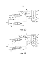
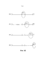
На фиг. 2A показана система 30 циркуляции текучей среды, предназначенная для регулирования средств перемещения нагнетательной головки, показанной на фиг. 1. На фиг. 2A нагнетательная головка 24 показана весьма схематично для упрощения чертежа.In FIG. 2A shows a
Как схематично показано на фиг. 2A, средства перемещения нагнетательной головки 24 содержат исполнительный механизм 32, который, к примеру, является исполнительным механизмом с гидравлическим или пневматическим приводом.As schematically shown in FIG. 2A, the means for moving the
Нагнетательная головка функционально соединена с исполнительным механизмом 32 и перемещается по продольной оси А.The discharge head is functionally connected to the
Исполнительный механизм 32, в частности, содержит поршень 34. который скользит в продольном направлении в цилиндрическом корпусе 36 по продольной оси А.The
Поршень 34 имеет основание 34a и шток 34b, прикрепленный к основанию на одном конце и прикрепленный к нагнетательной головке 24 на противоположном конце.The
Текучая среда, используемая для приведения в действие исполнительного механизма 32, к примеру, является воздухом.The fluid used to drive the
Как вариант, могут использоваться другие текучие среды, например, масло или вода.Alternatively, other fluids, such as oil or water, may be used.
Система 30 циркуляции текучей среды содержит управляющие средства 38 для управления подачей текучей среды к исполнительному механизму 32.The
Управление подачей текучей среды обеспечивает надлежащее перемещение нагнетательной головки 24.Fluid control ensures proper movement of the
Следует отметить, что в настоящем варианте выполнения ось A совпадает с вертикальной осью и, следовательно, перемещения нагнетательной головки, в общем, будут именоваться как перемещения вверх и вниз.It should be noted that in the present embodiment, the axis A coincides with the vertical axis and, therefore, the displacements of the discharge head, in general, will be referred to as displacements up and down.
Это не уменьшает объем изобретения, поскольку ось A может быть, как вариант, наклонена к вертикальной оси под углом, который больше 0° и меньше 90°.This does not reduce the scope of the invention, since the axis A can optionally be inclined to the vertical axis at an angle that is greater than 0 ° and less than 90 °.
Как схематично показано на фиг. 2A, управляющие средства 38 содержат главный клапан 40, также обозначенный как ОР12, который соединен с исполнительным механизмом 32 соответственно на двух участках. Эти два участка 32d и 32e сообщаются с раздельными камерами.As schematically shown in FIG. 2A, the control means 38 comprise a
Две раздельные камеры, обозначенные на фиг. 2A как 32a и 32b, отделены друг от друга основанием 34b поршня 34.The two separate chambers indicated in FIG. 2A as 32a and 32b are separated from each other by the base 34b of the
Управляющие средства 38 также содержат дополнительный вспомогательный клапан, который также обозначен как ОР30 и функционально связан с исполнительным механизмом 32.The control means 38 also comprise an additional auxiliary valve, which is also referred to as OP30 and is operatively connected to the
Каждый основной клапан 40 и вспомогательный клапан 42 соединены с общим источником S среды.Each
Следует отметить, что каждый клапан может находиться в двух главных состояниях или занимать два главных положения: положение, в котором он является открытым и обеспечивает прохождение потока текучей среды, и закрытое положение, в котором прохождение потока текучей среды заблокировано.It should be noted that each valve can be in two main states or occupy two main positions: the position in which it is open and allows the flow of fluid, and the closed position in which the flow of the fluid is blocked.
В частности, каждый клапан является, к примеру, электрическим клапаном типа 5/2, т.е. имеющим пять отверстий и 2 положения. При отсутствии электрического сигнала (установка на 0), посылаемого к клапану, возвратная пружина 41 обеспечивает сообщение между отверстиями 1 и 2 (подача), а также отверстиями 4 и 5 (выпуск). Когда электрический сигнал посылается к отверстию 1, отверстия 1 и 4 (подача), а также отверстия 2 и 3 (выпуск) сообщаются.In particular, each valve is, for example, an
Как, в частности, показано на фиг. 2A, управляющие средства 38 содержат первую линию или трубопровод 38a для текучей среды, соединяющий источник S текучей среды с главным клапаном 40, и вторую линию 38b подачи, соединяющую источник S текучей среды со вспомогательным клапаном 42.As shown in particular in FIG. 2A, the control means 38 comprise a first fluid line or
Управляющие средства 38 также содержат другую линию 38 с для текучей среды, соединяющую главный клапан 40 с первым участком 32d исполнительного механизма 32.The control means 38 also comprise another fluid line 38 s connecting the
Еще одна линия 38d соединяет главный клапан 40 со вторым участком 32e исполнительного механизма 32.Another
Эта линия для текучей среды также содержит регулятор 44 расхода (средство уменьшения расхода текучей среды), который расположен параллельно противовозвратному клапану 46.This fluid line also includes a flow regulator 44 (means for reducing the flow of fluid), which is parallel to the
Управляющие средства 38 также содержат линию 38e для текучей среды, соединяющую вспомогательный клапан со вторым участком 32e.The control means 38 also comprise a
Линия 38e для текучей среды также содержит противовозвратный клапан 48. Линии 38d и 38e для текучей среды имеют общий участок 38f, который соединен со вторым участком 32e.The
Как будет подробно описано ниже, главный клапан 40 и вспомогательный клапан 42 расположены параллельно, так чтобы расход текучей среды, которая подается с помощью вспомогательного клапана 42, добавлялся к расходу текучей среды, которая подается с помощью главного клапана 40, во время последнего этапа по способу изобретения.As will be described in detail below, the
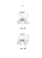
Способ по изобретению будет описан со ссылкой на фиг. 2B-E, 3A-D и 4A-C.The method of the invention will be described with reference to FIG. 2B-E, 3A-D and 4A-C.
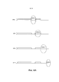
На фиг. 3A показано герметичное положение между нагнетательной головкой 24 и разливным отверстием 16 контейнера 14.In FIG. 3A shows a sealed position between the
Плотный контакт (непроницаемость для текучей среды) достигается с помощью известных способов, которые здесь не описываются.Tight contact (impermeability to the fluid) is achieved using known methods that are not described here.
Фиг. 3A идентична фиг. 1.FIG. 3A is identical to FIG. one.
Начиная с герметичного положения, показанного на фиг. 3A, способ по изобретению обеспечивает возможность дегазирования контейнера 14, наполненного газированным напитком с помощью нескольких этапов или фаз, описанных ниже.Starting from the sealed position shown in FIG. 3A, the method of the invention allows degassing of a
Начиная с герметичного положения на фиг. 3A, способ предлагает первый этап или фазу, во время которой нагнетательная головка 24 принудительно перемещается из герметичного положения в первое негерметичное положение, обозначенное позицией 1 на фиг. 4C.Starting from the sealed position in FIG. 3A, the method proposes a first step or phase during which the
Первое негерметичное положение показано на фиг. 3B. При этом показано, что между нагнетательной головкой 24 и кольцом 20 горлышка существует небольшой зазор «g».The first leaky position is shown in FIG. 3B. It is shown that between the
Перемещение из герметичного положения достигается посредством управления течением текучей среды, как показано на фиг. 2B.The movement from the sealed position is achieved by controlling the flow of fluid, as shown in FIG. 2B.
Как показано на фиг. 2B, среда, поступающая из источника S текучей среды к главному клапану 40 по линии 38a для текучей среды, затем проходит по последней, течет последовательно по линии 38d, регулятору 44 расхода и общей линии 38f и достигает второго участка 32e исполнительного механизма 32.As shown in FIG. 2B, the fluid coming from the fluid source S to the
Во время этого первого этапа или фазы главный клапан 40 принудительно закрывается (переключается из состояния 1 в состояние 0 на фиг. 4A), и вспомогательный клапан 42 удерживается в закрытом положении (положение на 0 на фиг. 4B).During this first stage or phase, the
Среда, таким образом, подается во вторую камеру 32b исполнительного механизма 32, поднимая нагнетательную головку 24 и перемещая ее из герметичного положения.The medium is thus supplied to the
За счет использования средства 44 уменьшения расхода текучей среды перемещение вверх нагнетательной головки 24 является относительно медленным и эффективно управляется, как показано на фиг. 4C.By using the fluid flow reduction means 44, the upward movement of the
Этот первый этап инициирует выпуск газа из разливного отверстия 16 в атмосферу.This first step initiates the release of gas from the tapping
Назначение этого способа состоит в дегазировании газированной жидкости, содержащейся в контейнере, без вспенивания.The purpose of this method is to degass the carbonated liquid contained in the container without foaming.
Обратное перемещение из положения, показанного на фиг. 3B, в герметичное положение, показанное на фиг. 3C, достигается, как показано на фиг. 2C и фиг. 4A-4C.Reverse movement from the position shown in FIG. 3B to the sealed position shown in FIG. 3C is achieved as shown in FIG. 2C and FIG. 4A-4C.
В частности, нагнетательная головка 24 принудительно перемещается назад, выполняя перемещение в нижнем направлении за счет функционирования главного клапана 40 (изменяющего свое состояние с 0 на 1 с целью открывания), при этом вспомогательный клапан 42 удерживается в закрытом положении (положение на 0).In particular, the
Открывание главного клапана 40 позволяет текучей среде проходить через него и протекать по линии 38 с для текучей среды к первому участку 32d исполнительного механизма 32.Opening the
Эта подача текучей среды к исполнительному механизму 32 оказывает воздействие на основание 34a, которое, таким образом, вынуждает поршень 34b скользить вниз вместе с нагнетательной головкой 24.This fluid supply to
Текучая среда, которая присутствует в камере 32b, выпускается через второй участок 32e и вытекает последовательно по линиям 38f и 38d.The fluid that is present in the
Следует отметить, что в этом направлении протекание осуществляется в обход регулятора 44 расхода благодаря наличию противовозвратного клапана 46.It should be noted that in this direction, the flow is bypassed by the
Эта компоновка позволяет ускорить возвратное перемещение нагнетательной головки по сравнению с перемещением из герметичного положения во время первого этапа или фазы.This arrangement makes it possible to accelerate the return movement of the discharge head as compared to moving from the sealed position during the first stage or phase.
Следует отметить, что после достижения герметичного положения, показанного на фиг. 3C, следующий этап перемещения нагнетательной головки из герметичного положения не начинается незамедлительно.It should be noted that after reaching the sealed position shown in FIG. 3C, the next step of moving the discharge head from the sealed position does not begin immediately.
Как показано на фиг. 3C и 4C, главный клапан 40 остается открытым в течение заданного периода времени перед закрыванием, и в течение этого периода времени сохраняется герметичное положение.As shown in FIG. 3C and 4C, the
Герметичное положение поддерживается с целью стабилизации процесса.The tight position is maintained in order to stabilize the process.
Продолжительность этапа или фазы стабилизации зависит от других этапов перемещения нагнетательной головки с целью выпуска газа в атмосферу, скорости перемещений нагнетательной головки из герметичного положения (скорости цилиндра 32) и жидкости или газированного напитка.The duration of the stabilization step or phase depends on the other steps of moving the discharge head to release gas into the atmosphere, the speed of movement of the discharge head from its sealed position (cylinder speed 32), and liquid or carbonated drink.
Способ по изобретению предусматривает последующие этапы или фазы для перемещения нагнетательной головки из герметичного положения.The method according to the invention provides the following steps or phases for moving the discharge head from the sealed position.
Это перемещение показано, начиная с положения на фиг. 3C и заканчивая положением на фиг. 3D.This movement is shown starting from the position in FIG. 3C and ending with the position in FIG. 3D
На фиг. 2D совместно с фиг. 4C показан третий этап или фаза способа.In FIG. 2D in conjunction with FIG. 4C shows a third step or phase of a method.
Третий этап или фаза, показанная на фиг. 4A-4C, выполняется посредством закрывания главного клапана 40, при этом вспомогательный клапан 42 удерживается в закрытом состоянии.The third step or phase shown in FIG. 4A-4C is performed by closing the
Во время этого этапа главный клапан 40 удерживается в закрытом положении в течение более длительного периода времени по сравнению с периодом времени на первом этапе.During this step, the
Поток текучей среды циркулирует, как уже было описано со ссылкой на фиг. 2B.A fluid stream circulates as already described with reference to FIG. 2B.
Это вынуждает нагнетательную головку 24 перемещаться из герметичного положения, показанного на фиг. 3C, с такой же скоростью, как и во время первого этапа, и в течение большего периода времени.This forces the
Это обеспечивает достижение второго негерметичного положения, показанного цифрой 2 на фиг. 4C и также показанного на фиг. 3D.This ensures that the second non-leaking position, indicated by 2 in FIG. 4C and also shown in FIG. 3D
Во время этого второго этапа дегазирования жидкости (первый этап показан на фиг. 2B и 4C) все еще необходимо медленное перемещение вверх нагнетательной головки во избежание вспенивания и расплескивания. Достигнутое второе негерметичное положение 2 необязательно должно быть дальше от герметичного положения по сравнению с негерметичным положением 1 (см. фиг. 4C). Второе негерметичное положение 2 зависит от нескольких параметров, включая сюда тип жидкости.During this second liquid degassing step (the first step is shown in FIGS. 2B and 4C), a slow upward movement of the discharge head is still necessary to prevent foaming and splashing. The achieved second
Это положение, а также первое негерметичное положение зависят от скорости перемещений нагнетательной головки и продолжительности этапов.This position, as well as the first leaky position, depend on the speed of the discharge head and the duration of the steps.
Эти параметры должны быть отрегулированы в самом устройстве для обеспечения наилучшего качества дегазирования, в значительной мере зависящего от жидкости (например, скорости газирования и т.д.).These parameters must be adjusted in the device itself to ensure the best degassing quality, which is largely dependent on the liquid (for example, carbonation rate, etc.).
Следует отметить, что скорость нагнетательной головки во время третьего этапа или фазы может быть выше или ниже скорости во время первого этапа или фазы, или даже может быть равна ей, в зависимости от жидкости, содержащейся в контейнере. Кроме того, продолжительность этапов может надлежащим образом регулироваться.It should be noted that the speed of the discharge head during the third stage or phase may be higher or lower than the speed during the first stage or phase, or may even be equal to it, depending on the liquid contained in the container. In addition, the duration of the steps can be appropriately adjusted.
Способ по изобретению предусматривает четвертый этап или фазу, которая обеспечивает ускорение перемещения от нагнетательной головки, как показано на фиг. 2E и 4C.The method of the invention provides a fourth step or phase that accelerates movement from the discharge head, as shown in FIG. 2E and 4C.
Во время этого этапа или фазы нагнетательная головка 24 принудительно перемещается дальше от герметичного положения на фиг. 3C в следующее негерметичное положение (обозначено цифрой 3 на фиг. 4C).During this step or phase, the
Это перемещение вверх выполняется с более высокой скоростью по сравнению с предыдущим перемещением вверх (третий этап или фаза), показанным на фиг. 2D вместе с фиг. 4C.This upward movement is performed at a higher speed than the previous upward movement (third stage or phase) shown in FIG. 2D together with FIG. 4C.
Это ускоренное перемещение достигается благодаря использованию вспомогательного клапана 42.This accelerated movement is achieved through the use of
До этого момента вспомогательный клапан 42 оставался в состоянии 0 (закрытое положение).Until that moment,
Во время этого четвертого этапа вспомогательный клапан 42 принудительно занимает открытое положение, в котором текучая среда, поступающая из источника S текучей среды, направляется к вспомогательному клапану 42 по линии 38b и проходит через него. Затем она последовательно протекает по линиям 38e и 38f, прежде чем достичь второго участка 32e исполнительного механизма 32.During this fourth step, the
Одновременно с циркуляцией этого потока среды параллельный поток среды направляется через главный клапан 40, регулятор 44 и общую линию 38f.Simultaneously with the circulation of this medium flow, a parallel medium flow is directed through the
Таким образом, в камеру 32b исполнительного механизма 32 нагнетается увеличенное количество среды, что обеспечивает быстрое перемещение вверх поршня 34b и прикрепленной к нему нагнетательной головки.Thus, an increased amount of medium is pumped into the
Это ускоренное перемещение позволяет уменьшить общее время цикла.This accelerated movement reduces the total cycle time.
В конце этого четвертого этапа или фазы достигается третье негерметичное положение, обозначенное цифрой 3 на фиг. 4C.At the end of this fourth step or phase, a third leaky position is reached, indicated by 3 in FIG. 4C.
Когда выполнение этапов способа подходит к концу, газ выпускается из разливного отверстия контейнера в атмосферу. Это достигается с помощью управляемых этапов или фаз посредством процесса постепенного выпуска газа. Перемещения нагнетательной головки управляются и регулируются таким образом, чтобы обеспечить планомерное и эффективное дегазирование газированного напитка.When the implementation of the method steps comes to an end, gas is discharged from the tapping opening of the container into the atmosphere. This is achieved through controlled steps or phases through a gradual gas release process. The movements of the discharge head are controlled and regulated in such a way as to ensure the systematic and effective degassing of the carbonated drink.
Следует отметить, что если процесс дегазирования должен был бы выполняться за один этап перемещения нагнетательной головки из герметичного положения, скорость нагнетательной головки была бы меньше скорости по настоящему изобретению во избежание вспенивания и расплескивания. Следовательно, время цикла превышало бы время цикла по настоящему изобретению.It should be noted that if the degassing process were to be performed in one step of moving the discharge head from the sealed position, the speed of the discharge head would be less than the speed of the present invention in order to avoid foaming and splashing. Therefore, the cycle time would exceed the cycle time of the present invention.
Claims (30)
Applications Claiming Priority (3)
| Application Number | Priority Date | Filing Date | Title |
|---|---|---|---|
| EP11176854 | 2011-08-08 | ||
| EP11176854.5 | 2011-08-08 | ||
| PCT/EP2012/065114 WO2013020883A1 (en) | 2011-08-08 | 2012-08-02 | Method of degasification of a carbonated beverage-filled container |
Publications (2)
| Publication Number | Publication Date |
|---|---|
| RU2014108771A RU2014108771A (en) | 2015-09-20 |
| RU2619276C2 true RU2619276C2 (en) | 2017-05-15 |
Family
ID=46614482
Family Applications (1)
| Application Number | Title | Priority Date | Filing Date |
|---|---|---|---|
| RU2014108771A RU2619276C2 (en) | 2011-08-08 | 2012-08-02 | Method for degassing container filled with carbonated beverage |
Country Status (9)
| Country | Link |
|---|---|
| US (2) | US9745181B2 (en) |
| EP (1) | EP2741962B1 (en) |
| JP (1) | JP6141843B2 (en) |
| CN (1) | CN103717494B (en) |
| BR (1) | BR112014000484B1 (en) |
| CA (1) | CA2836883C (en) |
| MX (1) | MX348925B (en) |
| RU (1) | RU2619276C2 (en) |
| WO (1) | WO2013020883A1 (en) |
Families Citing this family (5)
| Publication number | Priority date | Publication date | Assignee | Title |
|---|---|---|---|---|
| CN103717494B (en) * | 2011-08-08 | 2015-11-25 | 帝斯克玛股份有限公司 | Be filled with the degas method of the container of soda |
| WO2017086915A1 (en) | 2015-11-16 | 2017-05-26 | Discma Ag | Method of forming a container using a liquid |
| DE102017109112A1 (en) * | 2017-04-27 | 2018-10-31 | Norgren Ag | Device for compressed air control |
| DE102018106779A1 (en) | 2018-03-22 | 2019-09-26 | Krones Ag | Device for expanding plastic containers with shut-off valve between the pressure-generating device and the filling device |
| DE102021115729A1 (en) | 2021-06-17 | 2022-12-22 | Krones Aktiengesellschaft | Device and method for inspecting filled containers and their contents |
Citations (3)
| Publication number | Priority date | Publication date | Assignee | Title |
|---|---|---|---|---|
| DE1127241B (en) * | 1960-06-14 | 1962-04-05 | Holstein & Kappert Maschf | Method and device for emptying the bottles filled under pressure on bottle filling machines for carbonated beverages |
| WO2011076167A1 (en) * | 2009-12-23 | 2011-06-30 | Khs Gmbh | Method and device for producing filled containers |
| RU2496692C2 (en) * | 2008-07-07 | 2013-10-27 | Нестек С.А. | Device for packing liquid food product |
Family Cites Families (56)
| Publication number | Priority date | Publication date | Assignee | Title |
|---|---|---|---|---|
| US1686811A (en) * | 1922-05-15 | 1928-10-09 | Greenhouse Samuel | Bottle-filling machine |
| NL284490A (en) * | 1961-10-25 | 1900-01-01 | ||
| DE1482619C3 (en) * | 1965-03-31 | 1975-02-20 | Enzinger-Union-Werke Ag, 6800 Mannheim | Counter pressure filling device for filling carbonated drinking liquids into vessels |
| DE1482630A1 (en) * | 1965-12-29 | 1969-01-16 | Holstein & Kappert Maschf | Differential pressure filling valve |
| US3645303A (en) * | 1970-09-08 | 1972-02-29 | Ato Inc | Filling apparatus |
| JPS5023472B1 (en) * | 1970-12-28 | 1975-08-07 | ||
| DE2234120C3 (en) * | 1972-07-12 | 1979-08-09 | Seitz-Werke Gmbh, 6550 Bad Kreuznach | Filling element with long downpipe for multi-chamber counter pressure filling machines |
| GB1474044A (en) * | 1974-12-03 | 1977-05-18 | Ici Ltd | Plastics container manufacture |
| JPS53107794U (en) * | 1977-02-03 | 1978-08-29 | ||
| DE2800972B2 (en) * | 1978-01-11 | 1980-03-06 | Ortmann & Herbst Gmbh, 2000 Hamburg | Container filling element with piston / cylinder stroke arrangement |
| US4707966A (en) * | 1981-08-26 | 1987-11-24 | Automatic Liquid Packaging, Inc. | Container with an encapsulated top insert and method and apparatus for making same |
| US4403940A (en) * | 1981-10-28 | 1983-09-13 | The Continental Group, Inc. | Blow head valve |
| US5038548A (en) * | 1983-07-29 | 1991-08-13 | Sieg William F | Defoaming method and apparatus |
| DE3920977A1 (en) * | 1989-06-27 | 1991-01-10 | Alfill Getraenketechnik | DEVICE FOR FILLING CONTAINERS |
| DE4324592C1 (en) * | 1993-07-22 | 1995-01-12 | Kronseder Maschf Krones | Method and device for pouring liquid into vessels |
| JP2856057B2 (en) * | 1993-12-28 | 1999-02-10 | 東洋製罐株式会社 | Method and apparatus for filling carbonated beverages |
| FR2764544B1 (en) * | 1997-06-16 | 1999-09-24 | Sidel Sa | NOZZLE FOR BLOWING PLASTIC CONTAINERS AND INSTALLATION PROVIDED WITH SUCH A NOZZLE |
| GB9818179D0 (en) * | 1998-08-21 | 1998-10-14 | Univ Manchester | Foam control |
| FR2804059B1 (en) * | 2000-01-20 | 2002-08-30 | Sidel Sa | CONTAINER BLOWING MACHINE COMPRISING MEANS FOR ORIENTATION OF PREFORMS IN THE BLOW MOLD |
| FR2814392B1 (en) * | 2000-09-25 | 2002-12-20 | Sidel Sa | STRETCH-BLOWING MACHINE HAVING IMPROVED DRAWING ROD CONTROL |
| DE20018500U1 (en) * | 2000-10-28 | 2001-12-13 | Krones Ag | Blowing machine |
| FR2839277B1 (en) * | 2002-05-03 | 2005-04-08 | Nestle Waters Man & Technology | PROCESS FOR MANUFACTURING A POLYESTER RESIN CONTAINER AND DEVICE FOR IMPLEMENTING IT |
| ATE423670T1 (en) | 2003-11-06 | 2009-03-15 | Nestle Waters Man & Technology | PROCESS OF PRODUCTION OF POLYESTER RESIN CONTAINERS |
| FR2876942B1 (en) * | 2004-10-22 | 2008-08-15 | Sidel Sas | BLOWING INSTALLATION FOR THE MANUFACTURE OF THERMOPLASTIC CONTAINERS |
| MY146226A (en) * | 2005-04-25 | 2012-07-31 | Advanced Tech Materials | Material storage and dispensing packages and methods |
| FR2889673B1 (en) * | 2005-08-12 | 2007-10-26 | Sidel Sas | BLOWING INSTALLATION COMPRISING A PIPE EQUIPPED WITH A LIP SEAL |
| WO2007086339A1 (en) * | 2006-01-26 | 2007-08-02 | Toyo Seikan Kaisha, Ltd. | Defoaming method |
| US8573964B2 (en) * | 2006-04-13 | 2013-11-05 | Amcor Limited | Liquid or hydraulic blow molding |
| US7914726B2 (en) * | 2006-04-13 | 2011-03-29 | Amcor Limited | Liquid or hydraulic blow molding |
| JP4990368B2 (en) * | 2006-11-29 | 2012-08-01 | シデル ホールディングス アンド テクノロジー エスエー | Filling valve unit |
| FR2912678B1 (en) * | 2007-02-16 | 2013-02-15 | Sidel Participations | TUYERE FOR A MACHINE FOR MANUFACTURING CONTAINERS |
| FR2914876B1 (en) * | 2007-04-10 | 2009-07-10 | Sidel Participations | DEVICE FOR MOLDING, BY BLOWING OR STRETCH BLOWING, CONTAINERS OF THERMOPLASTIC MATERIAL |
| FR2914875B1 (en) * | 2007-04-13 | 2009-07-10 | Sidel Participations | MOLDING DEVICE FOR THE MANUFACTURE OF THERMOPLASTIC CONTAINERS BY BLOWING OR STRETCH BLOWING. |
| DE102007032434B4 (en) * | 2007-07-10 | 2019-08-22 | Krones Aktiengesellschaft | Blowing device for expanding containers |
| FR2918916B1 (en) * | 2007-07-19 | 2009-10-23 | Sidel Participations | INSTALLATION FOR THE MANUFACTURE OF CONTAINERS FROM A PREFORM AND METHOD FOR CONTROLLING THE BLOWING MEANS OF SUCH A INSTALLATION |
| FR2921582B1 (en) * | 2007-09-27 | 2013-11-22 | Sidel Participations | INSTALLATION FOR BLOWING CONTAINERS IN THERMOPLASTIC MATERIAL |
| US8017064B2 (en) * | 2007-12-06 | 2011-09-13 | Amcor Limited | Liquid or hydraulic blow molding |
| DE102008028754A1 (en) * | 2008-06-17 | 2009-12-24 | Bernd Hansen | Device for producing and filling containers |
| EP2143545A1 (en) * | 2008-07-07 | 2010-01-13 | Nestec S.A. | Method and apparatus for packaging a liquid food product |
| EP2143542A1 (en) * | 2008-07-07 | 2010-01-13 | Nestec S.A. | Method and apparatus for packaging a liquid food product |
| FR2940171B1 (en) * | 2008-12-24 | 2011-01-21 | Sidel Participations | BLOWING INSTALLATION FOR MANUFACTURING A CONTAINER FROM A DRAFT |
| DE102009011583A1 (en) * | 2009-03-06 | 2010-09-09 | Krones Ag | Method and device for producing and filling thin-walled beverage containers |
| DE102009014857B4 (en) * | 2009-03-30 | 2014-06-26 | Khs Gmbh | Method for filling bottles or similar containers and filling machine |
| FR2943941B1 (en) * | 2009-04-02 | 2011-04-22 | Sidel Participations | MOLDING UNIT WITH PILOTED TUYERE |
| JP5685835B2 (en) | 2010-06-03 | 2015-03-18 | 株式会社リコー | Drop discharge state detection device, image forming apparatus, and image forming system |
| JP5669490B2 (en) * | 2010-09-10 | 2015-02-12 | 有限会社村上商店 | Foaming liquid filling equipment |
| EP2463079A1 (en) * | 2010-12-10 | 2012-06-13 | Nestec S.A. | A process for single-step forming and filling of containers |
| CN103717494B (en) * | 2011-08-08 | 2015-11-25 | 帝斯克玛股份有限公司 | Be filled with the degas method of the container of soda |
| WO2013063453A1 (en) * | 2011-10-27 | 2013-05-02 | Amcor Limited | Method and apparatus for forming and filling a container |
| CN104039526B (en) * | 2011-12-21 | 2017-08-08 | 帝斯克玛股份有限公司 | sealing system for forming machine |
| US9610744B2 (en) * | 2011-12-27 | 2017-04-04 | Discma Ag | Blow molding device and a method for manufacturing a container |
| EP2617650B1 (en) * | 2012-01-17 | 2014-08-20 | Nestec S.A. | Apparatus for blowing and filling a container with liquid collecting means |
| EP2812172B1 (en) * | 2012-02-10 | 2022-10-19 | Discma AG | A method of blowing, filling and capping containers |
| EP2636603A1 (en) * | 2012-03-08 | 2013-09-11 | Nestec S.A. | A method and apparatus for blowing and filling containers with release of liquid overpressure |
| DE102012015087A1 (en) * | 2012-08-01 | 2014-05-15 | Khs Corpoplast Gmbh | Method and device for producing filled with a liquid product containers |
| JP6072250B2 (en) * | 2012-08-03 | 2017-02-01 | 株式会社吉野工業所 | Method and apparatus for manufacturing containers |
-
2012
- 2012-08-02 CN CN201280037933.7A patent/CN103717494B/en active Active
- 2012-08-02 MX MX2014000461A patent/MX348925B/en active IP Right Grant
- 2012-08-02 WO PCT/EP2012/065114 patent/WO2013020883A1/en active Application Filing
- 2012-08-02 US US14/236,827 patent/US9745181B2/en active Active
- 2012-08-02 CA CA2836883A patent/CA2836883C/en active Active
- 2012-08-02 BR BR112014000484-6A patent/BR112014000484B1/en active IP Right Grant
- 2012-08-02 JP JP2014524338A patent/JP6141843B2/en active Active
- 2012-08-02 EP EP12743447.0A patent/EP2741962B1/en active Active
- 2012-08-02 RU RU2014108771A patent/RU2619276C2/en active
-
2017
- 2017-04-24 US US15/495,046 patent/US10501302B2/en active Active
Patent Citations (3)
| Publication number | Priority date | Publication date | Assignee | Title |
|---|---|---|---|---|
| DE1127241B (en) * | 1960-06-14 | 1962-04-05 | Holstein & Kappert Maschf | Method and device for emptying the bottles filled under pressure on bottle filling machines for carbonated beverages |
| RU2496692C2 (en) * | 2008-07-07 | 2013-10-27 | Нестек С.А. | Device for packing liquid food product |
| WO2011076167A1 (en) * | 2009-12-23 | 2011-06-30 | Khs Gmbh | Method and device for producing filled containers |
Non-Patent Citations (2)
| Title |
|---|
| RU 2496692 C2, публ. заявки * |
| WO 2011/076167 A1, весь документ. * |
Also Published As
| Publication number | Publication date |
|---|---|
| US9745181B2 (en) | 2017-08-29 |
| CN103717494B (en) | 2015-11-25 |
| BR112014000484A2 (en) | 2017-02-21 |
| JP6141843B2 (en) | 2017-06-07 |
| US20140174032A1 (en) | 2014-06-26 |
| US10501302B2 (en) | 2019-12-10 |
| WO2013020883A1 (en) | 2013-02-14 |
| CA2836883C (en) | 2019-02-12 |
| BR112014000484B1 (en) | 2020-06-30 |
| EP2741962A1 (en) | 2014-06-18 |
| MX348925B (en) | 2017-07-03 |
| MX2014000461A (en) | 2014-02-20 |
| RU2014108771A (en) | 2015-09-20 |
| EP2741962B1 (en) | 2019-10-30 |
| US20170225934A1 (en) | 2017-08-10 |
| JP2014529551A (en) | 2014-11-13 |
| CA2836883A1 (en) | 2013-02-14 |
| CN103717494A (en) | 2014-04-09 |
Similar Documents
| Publication | Publication Date | Title |
|---|---|---|
| RU2619276C2 (en) | Method for degassing container filled with carbonated beverage | |
| EP3381654B1 (en) | Liquid blow molding method | |
| WO2017187698A1 (en) | Liquid blow molding method | |
| JP7174057B2 (en) | Manufacturing method of container containing liquid | |
| JP6893870B2 (en) | Manufacturing method of liquid container | |
| US10456973B2 (en) | Blow molding apparatus and blow molding method | |
| EP3112126A1 (en) | Blow molding apparatus | |
| EP3685985B1 (en) | Liquid-containing container manufacturing method | |
| JP6853759B2 (en) | Manufacturing method of liquid container | |
| JP6629647B2 (en) | Liquid blow molding apparatus and liquid blow molding method | |
| JP7046785B2 (en) | Manufacturing method of liquid container | |
| WO2021039108A1 (en) | Blow molding device | |
| WO2019202865A1 (en) | Method for manufacturing liquid-containing container | |
| JP6853758B2 (en) | Manufacturing method of liquid container | |
| JP2022151134A (en) | Manufacturing method for liquid-filled container | |
| WO2022176423A1 (en) | Method for manufacturing liquid container | |
| JP7026595B2 (en) | Manufacturing method and equipment for liquid containers | |
| JP2021133668A (en) | Method for manufacturing liquid container |
Legal Events
| Date | Code | Title | Description |
|---|---|---|---|
| HE9A | Changing address for correspondence with an applicant | ||
| HZ9A | Changing address for correspondence with an applicant |