RU2617543C2 - Method of production and accumulation of electric power from human body, autonomous self-responsible power source and electronic device worn on human body - Google Patents
Method of production and accumulation of electric power from human body, autonomous self-responsible power source and electronic device worn on human body Download PDFInfo
- Publication number
- RU2617543C2 RU2617543C2 RU2013147931A RU2013147931A RU2617543C2 RU 2617543 C2 RU2617543 C2 RU 2617543C2 RU 2013147931 A RU2013147931 A RU 2013147931A RU 2013147931 A RU2013147931 A RU 2013147931A RU 2617543 C2 RU2617543 C2 RU 2617543C2
- Authority
- RU
- Russia
- Prior art keywords
- heat
- human body
- engine
- heat engine
- working fluid
- Prior art date
Links
- 238000000034 method Methods 0.000 title claims abstract description 25
- 238000004519 manufacturing process Methods 0.000 title description 6
- 238000009825 accumulation Methods 0.000 title description 3
- 239000012530 fluid Substances 0.000 claims abstract description 59
- 238000001816 cooling Methods 0.000 claims abstract description 35
- 238000010438 heat treatment Methods 0.000 claims abstract description 24
- 230000033001 locomotion Effects 0.000 claims abstract description 19
- 230000007246 mechanism Effects 0.000 claims description 31
- 230000005540 biological transmission Effects 0.000 claims description 25
- 239000007789 gas Substances 0.000 claims description 25
- 239000000463 material Substances 0.000 claims description 13
- XAGFODPZIPBFFR-UHFFFAOYSA-N aluminium Chemical compound [Al] XAGFODPZIPBFFR-UHFFFAOYSA-N 0.000 claims description 9
- CSCPPACGZOOCGX-UHFFFAOYSA-N Acetone Chemical compound CC(C)=O CSCPPACGZOOCGX-UHFFFAOYSA-N 0.000 claims description 8
- RYGMFSIKBFXOCR-UHFFFAOYSA-N Copper Chemical compound [Cu] RYGMFSIKBFXOCR-UHFFFAOYSA-N 0.000 claims description 8
- 239000010949 copper Substances 0.000 claims description 8
- BQCADISMDOOEFD-UHFFFAOYSA-N Silver Chemical compound [Ag] BQCADISMDOOEFD-UHFFFAOYSA-N 0.000 claims description 7
- 239000004332 silver Substances 0.000 claims description 7
- 229910001316 Ag alloy Inorganic materials 0.000 claims description 6
- 229910000881 Cu alloy Inorganic materials 0.000 claims description 6
- 229910052782 aluminium Inorganic materials 0.000 claims description 5
- 239000001257 hydrogen Substances 0.000 claims description 5
- 229910052739 hydrogen Inorganic materials 0.000 claims description 5
- 229910001020 Au alloy Inorganic materials 0.000 claims description 4
- LFQSCWFLJHTTHZ-UHFFFAOYSA-N Ethanol Chemical compound CCO LFQSCWFLJHTTHZ-UHFFFAOYSA-N 0.000 claims description 4
- 239000003570 air Substances 0.000 claims description 4
- 229910052802 copper Inorganic materials 0.000 claims description 4
- 239000011521 glass Substances 0.000 claims description 4
- 239000003353 gold alloy Substances 0.000 claims description 4
- 229910052734 helium Inorganic materials 0.000 claims description 4
- 239000001307 helium Substances 0.000 claims description 4
- SWQJXJOGLNCZEY-UHFFFAOYSA-N helium atom Chemical compound [He] SWQJXJOGLNCZEY-UHFFFAOYSA-N 0.000 claims description 4
- 239000003638 chemical reducing agent Substances 0.000 claims description 3
- 230000009347 mechanical transmission Effects 0.000 claims description 3
- 229910045601 alloy Inorganic materials 0.000 claims description 2
- 239000000956 alloy Substances 0.000 claims description 2
- 125000004435 hydrogen atom Chemical class [H]* 0.000 claims 2
- 229910052709 silver Inorganic materials 0.000 claims 2
- 239000000126 substance Substances 0.000 abstract description 8
- 230000000694 effects Effects 0.000 abstract description 7
- 230000005611 electricity Effects 0.000 abstract description 5
- 238000002485 combustion reaction Methods 0.000 description 9
- 230000006835 compression Effects 0.000 description 9
- 238000007906 compression Methods 0.000 description 9
- 238000013461 design Methods 0.000 description 9
- 238000012546 transfer Methods 0.000 description 9
- 230000008569 process Effects 0.000 description 6
- 230000008859 change Effects 0.000 description 5
- 229910000838 Al alloy Inorganic materials 0.000 description 4
- 230000005678 Seebeck effect Effects 0.000 description 4
- 239000002131 composite material Substances 0.000 description 4
- 239000004020 conductor Substances 0.000 description 4
- 125000004122 cyclic group Chemical group 0.000 description 4
- 238000011161 development Methods 0.000 description 4
- 239000004065 semiconductor Substances 0.000 description 4
- OKKJLVBELUTLKV-UHFFFAOYSA-N Methanol Chemical compound OC OKKJLVBELUTLKV-UHFFFAOYSA-N 0.000 description 3
- 230000009471 action Effects 0.000 description 3
- 239000003990 capacitor Substances 0.000 description 3
- 230000007423 decrease Effects 0.000 description 3
- 238000005516 engineering process Methods 0.000 description 3
- 239000000446 fuel Substances 0.000 description 3
- 229910052751 metal Inorganic materials 0.000 description 3
- 239000002184 metal Substances 0.000 description 3
- 239000004033 plastic Substances 0.000 description 3
- 229920003023 plastic Polymers 0.000 description 3
- OKTJSMMVPCPJKN-UHFFFAOYSA-N Carbon Chemical compound [C] OKTJSMMVPCPJKN-UHFFFAOYSA-N 0.000 description 2
- XUIMIQQOPSSXEZ-UHFFFAOYSA-N Silicon Chemical compound [Si] XUIMIQQOPSSXEZ-UHFFFAOYSA-N 0.000 description 2
- 238000010521 absorption reaction Methods 0.000 description 2
- 238000006243 chemical reaction Methods 0.000 description 2
- 238000010586 diagram Methods 0.000 description 2
- 230000007613 environmental effect Effects 0.000 description 2
- PCHJSUWPFVWCPO-UHFFFAOYSA-N gold Chemical compound [Au] PCHJSUWPFVWCPO-UHFFFAOYSA-N 0.000 description 2
- 229910052737 gold Inorganic materials 0.000 description 2
- 239000010931 gold Substances 0.000 description 2
- 150000002431 hydrogen Chemical class 0.000 description 2
- 150000002739 metals Chemical class 0.000 description 2
- 239000000203 mixture Substances 0.000 description 2
- 230000001172 regenerating effect Effects 0.000 description 2
- 229910052710 silicon Inorganic materials 0.000 description 2
- 239000010703 silicon Substances 0.000 description 2
- UFHFLCQGNIYNRP-UHFFFAOYSA-N Hydrogen Chemical compound [H][H] UFHFLCQGNIYNRP-UHFFFAOYSA-N 0.000 description 1
- HBBGRARXTFLTSG-UHFFFAOYSA-N Lithium ion Chemical compound [Li+] HBBGRARXTFLTSG-UHFFFAOYSA-N 0.000 description 1
- 238000004458 analytical method Methods 0.000 description 1
- 238000013459 approach Methods 0.000 description 1
- 229910052797 bismuth Inorganic materials 0.000 description 1
- JCXGWMGPZLAOME-UHFFFAOYSA-N bismuth atom Chemical compound [Bi] JCXGWMGPZLAOME-UHFFFAOYSA-N 0.000 description 1
- 229910052799 carbon Inorganic materials 0.000 description 1
- 230000008878 coupling Effects 0.000 description 1
- 238000010168 coupling process Methods 0.000 description 1
- 238000005859 coupling reaction Methods 0.000 description 1
- 230000003247 decreasing effect Effects 0.000 description 1
- 238000001514 detection method Methods 0.000 description 1
- 239000000806 elastomer Substances 0.000 description 1
- 229920001971 elastomer Polymers 0.000 description 1
- 230000005672 electromagnetic field Effects 0.000 description 1
- 230000005674 electromagnetic induction Effects 0.000 description 1
- 230000007717 exclusion Effects 0.000 description 1
- 238000002474 experimental method Methods 0.000 description 1
- 210000001061 forehead Anatomy 0.000 description 1
- 239000010439 graphite Substances 0.000 description 1
- 229910002804 graphite Inorganic materials 0.000 description 1
- 239000007943 implant Substances 0.000 description 1
- 238000009434 installation Methods 0.000 description 1
- 239000011810 insulating material Substances 0.000 description 1
- 230000003993 interaction Effects 0.000 description 1
- 229910001416 lithium ion Inorganic materials 0.000 description 1
- 229910052987 metal hydride Inorganic materials 0.000 description 1
- 238000004377 microelectronic Methods 0.000 description 1
- 239000002105 nanoparticle Substances 0.000 description 1
- 230000035764 nutrition Effects 0.000 description 1
- 235000016709 nutrition Nutrition 0.000 description 1
- 239000007800 oxidant agent Substances 0.000 description 1
- 238000000206 photolithography Methods 0.000 description 1
- 238000012545 processing Methods 0.000 description 1
- 239000000758 substrate Substances 0.000 description 1
- 239000003826 tablet Substances 0.000 description 1
- 229910052714 tellurium Inorganic materials 0.000 description 1
- PORWMNRCUJJQNO-UHFFFAOYSA-N tellurium atom Chemical compound [Te] PORWMNRCUJJQNO-UHFFFAOYSA-N 0.000 description 1
- 238000000233 ultraviolet lithography Methods 0.000 description 1
- XLYOFNOQVPJJNP-UHFFFAOYSA-N water Substances O XLYOFNOQVPJJNP-UHFFFAOYSA-N 0.000 description 1
- 210000000707 wrist Anatomy 0.000 description 1
Images
Classifications
-
- F—MECHANICAL ENGINEERING; LIGHTING; HEATING; WEAPONS; BLASTING
- F03—MACHINES OR ENGINES FOR LIQUIDS; WIND, SPRING, OR WEIGHT MOTORS; PRODUCING MECHANICAL POWER OR A REACTIVE PROPULSIVE THRUST, NOT OTHERWISE PROVIDED FOR
- F03G—SPRING, WEIGHT, INERTIA OR LIKE MOTORS; MECHANICAL-POWER PRODUCING DEVICES OR MECHANISMS, NOT OTHERWISE PROVIDED FOR OR USING ENERGY SOURCES NOT OTHERWISE PROVIDED FOR
- F03G7/00—Mechanical-power-producing mechanisms, not otherwise provided for or using energy sources not otherwise provided for
- F03G7/06—Mechanical-power-producing mechanisms, not otherwise provided for or using energy sources not otherwise provided for using expansion or contraction of bodies due to heating, cooling, moistening, drying or the like
-
- H—ELECTRICITY
- H02—GENERATION; CONVERSION OR DISTRIBUTION OF ELECTRIC POWER
- H02N—ELECTRIC MACHINES NOT OTHERWISE PROVIDED FOR
- H02N10/00—Electric motors using thermal effects
Landscapes
- Connection Of Motors, Electrical Generators, Mechanical Devices, And The Like (AREA)
- Charge And Discharge Circuits For Batteries Or The Like (AREA)
Abstract
Description
Область техникиTechnical field
Изобретение относится к области электронной промышленности, а более конкретно к электронным устройствам, работающим на автономном источнике питания и направлено на создание устройства и способа позволяющего обеспечить автономное бесперебойное питание за счет использования тепловой энергии, вырабатываемой человеческим телом.The invention relates to the field of electronic industry, and more particularly to electronic devices operating on an autonomous power source and is aimed at creating a device and method for providing an uninterrupted uninterrupted power supply through the use of thermal energy generated by the human body.
Уровень техникиState of the art
В современном мире электронные устройства играют важную и неотъемлемую роль в жизни человека. Практически не осталось сферы деятельности человека, где бы электронные устройства ни применялись. Появление первого электронного устройства связано с возникновением такой науки как электроника. Возникновению электроники предшествовало изобретение радио.In the modern world, electronic devices play an important and integral role in human life. There is practically no sphere of human activity, wherever electronic devices are used. The appearance of the first electronic device is associated with the emergence of such a science as electronics. The advent of electronics was preceded by the invention of radio.
Электроника (от греч. ![]()
![]()
Выделяют несколько этапов развития электроники.There are several stages in the development of electronics.
1 этап - до 1904 г.Stage 1 - until 1904
Который характеризуется открытием А. Лодыгином в 1873 г. лампы накаливания с угольным стержнем; открытие Т. Эдисон в 1883 г. явления термоэлектронной эмиссии; открытие Ф. Брауном в 1874 г. выпрямительного эффекта в контакте металла с полупроводником и использование А. Поповым в 1895 г. этот эффект для детектирования радиосигналов и т.д.Which is characterized by the discovery by A. Lodygin in 1873 of an incandescent lamp with a carbon rod; discovery of T. Edison in 1883 of the phenomenon of thermionic emission; the discovery by F. Brown in 1874 of the rectifying effect in the contact of a metal with a semiconductor and the use by A. Popov in 1895 of this effect for the detection of radio signals, etc.
2 этап - до 1948 г. - период развития вакуумных и газоразрядных электроприборов, где в 1904 г. Д. Флеминг сконструировал электровакуумный диод; в 1907 г. Ли-де-Форест изобрел триод; в 1920 году Бонч-Бруевич разработал генераторные лампы с медным анодом и водяным охлаждением, мощностью до 1 кВт; в 1924 г. Хеллом разработана экранированная лампа с двумя сетками (тетрод) и в 1930 г. лампа с тремя сетками (пентод); в 1929 г. В. Зворыкиным был изобретен кинескоп; с 30-х годов ведется разработка приборов СВЧ-диапазона и т.д.Stage 2 - until 1948 - the period of development of vacuum and gas-discharge electrical appliances, where in 1904 D. Fleming designed an electrovacuum diode; in 1907, Li de Forest invented the triode; in 1920 Bonch-Bruyevich developed generator lamps with a copper anode and water cooling, with a capacity of up to 1 kW; in 1924, Hell developed a shielded lamp with two grids (tetrode) and in 1930 a lamp with three grids (pentode); in 1929, V. Zvorykin invented a kinescope; since the 30s, microwave devices have been developed, etc.
3 этап - с 1948 г. - период создания и внедрения дискретных полупроводниковых приборов.Stage 3 - since 1948 - the period of creation and implementation of discrete semiconductor devices.
4 этап - с 1960 г. - период развития микроэлектроники. Роберт Нойс предложил идею монолитной интегральной схемы и, применив планарную технологию, изготовил первые кремниевые монолитные интегральные схемы. Поскольку радиопередатчики сразу же нашли применение (в первую очередь на кораблях и в военном деле), для них потребовалась элементная база, созданием и изучением которой и занялась электроника.Stage 4 - since 1960 - the period of development of microelectronics. Robert Neuss proposed the idea of a monolithic integrated circuit and, using planar technology, manufactured the first silicon monolithic integrated circuits. Since the radio transmitters immediately found application (primarily on ships and in military affairs), they required an element base, the creation and study of which electronics took up.
С развитием электроники появлялись новые электронные устройства, развивались и претерпели изменения старые электронные устройства. Некогда громоздкие и требующих огромных энергетических затрат электронные устройства стали гораздо меньше по габаритам и уменьшились их энергетические затраты для функционирования.With the development of electronics, new electronic devices appeared, and old electronic devices developed and changed. Once cumbersome and requiring huge energy costs, electronic devices have become much smaller in size and reduced their energy costs for operation.
Электроника стала неотъемлемой частью в жизни человека и проникла во все сферы его деятельности, что существенно упростила жизнь человеку.Electronics has become an integral part in human life and has penetrated into all spheres of its activity, which greatly simplified human life.
Но с активным применением электронных устройств, в частности переносных электронных устройств работающих от автономных источников питания, человек столкнулся с одной существенной проблемой, которая заключалась в том, что при истощении запасов энергии источника питания его необходимо либо заменять на новый, либо постоянно подзаряжать его.But with the active use of electronic devices, in particular portable electronic devices operating from autonomous power sources, a person faced one significant problem, which was that when the energy reserves of a power source are depleted, it must either be replaced with a new one or constantly recharged.
Данная проблема актуальна не только сточки зрения техники и экономики, но существенна с точки зрения экологии, потому что постоянное использование одноразовых источников питания влечет за собою ряд последствии оказывающих побочные действия на окружающую среду (утилизация старых и постоянное и возрастающее производство новых), а использование источников многоразового действия из-за постоянной их подзарядки от цепи также влияют на экологию земли, так как существенно увеличивают энергозатраты.This problem is relevant not only from the point of view of technology and economics, but also significant from an environmental point of view, because the constant use of disposable food sources entails a number of consequences that have side effects on the environment (the disposal of old and the constant and increasing production of new ones), and the use of sources reusable actions due to their constant recharging from the circuit also affect the ecology of the earth, since they significantly increase energy costs.
Решения данной проблемы человечество решило искать в уменьшении размеров и использовании естественных источниках питания.Mankind decided to search for solutions to this problem in reducing the size and use of natural sources of nutrition.
Так, известны попытки специалистов из Великобритании получить микроскопический поршневой двигатель внутреннего сгорания (ДВС) [1].Thus, attempts by specialists from the UK to obtain a microscopic piston internal combustion engine (ICE) are known [1].
В частности профессором Симоной Хохгреб (Simone Hochgreb) из Центра исследования горения университета Кембриджа (Combustion Research Centre of Cambridge University) и доктором Кили Цзян (Kyle Jiang) из Центра микроинжиниринга и нанотехнологий университета Бирмингема (Micro-Engineering and Nano-Technology Research Centre of University of Birmingham) был спроектирован двигатель с объемом камеры сгорания порядка одного кубического миллиметра. Детали этих двигателей - плоские. Поршни представляют собой крошечные пластинки, выполненные методом ультрафиолетовой литографии. Поршни движутся, будучи закрытыми с краев фигурной пластиной, играющей роль корпуса, а сверху и снизу - такими же плоскими крышками. ДВС, созданные британскими учеными представляют собой классические дизельные двигатели, работающие на метаноловых смесях (с добавкой водорода), способных самостоятельно вспыхивать при такте сжатия.In particular, Professor Simone Hochgreb of the Combustion Research Center of Cambridge University and Dr. Kyle Jiang of the Center for Microengineering and Nanotechnology of the University of Birmingham (Micro-Engineering and Nano-Technology Research Center of University of Birmingham) was designed engine with a combustion chamber volume of the order of one cubic millimeter. Parts of these engines are flat. Pistons are tiny plates made by ultraviolet lithography. Pistons move, being closed at the edges by a figured plate, which plays the role of a body, and above and below - with the same flat covers. ICEs created by British scientists are classic diesel engines running on methanol mixtures (with the addition of hydrogen) that can independently flash during a compression stroke.
Однако есть ряд недостатков, один из которых связан с тем, что компоненты на базе кремния плохо сочетаются с высокими температурами в зоне сгорания. Кроме этого имеют место огромные теплопотери через стенки. Для двигателя размером в несколько миллиметров потери оказываются куда большими, относительно энергии, получаемой от сгорания топлива, чем для обычных ДВС.However, there are a number of drawbacks, one of which is due to the fact that silicon-based components do not combine well with high temperatures in the combustion zone. In addition, there are huge heat losses through the walls. For an engine several millimeters in size, the losses are much greater relative to the energy received from the combustion of fuel than for conventional ICEs.
Известен миниатюрный термоэлемент, разработанный компанией Thermo Life Energy, генерирующий энергию для датчиков, имплантатов и чипов за счет самых небольших перепадов температур [2].Known miniature thermoelement, developed by Thermo Life Energy, generating energy for sensors, implants and chips due to the smallest temperature differences [2].
Термоэлектрические элементы, представляющие собой набор из ряда термопар, составленных из определенных веществ (полупроводники, металлы), вырабатывают ток при возникновении разницы температур двух концов этих пар. То есть в данном устройстве применяется известный эффект Зеебека. Эффект Зеебека состоит в том, что в электрической цепи, составленной из разных проводников, возникает термоэдс, если места контактов поддерживаются при разных температурах. [3] Если цепь замкнута, то в ней течет электрический ток (так называемый термоток), причем изменение знака у разности температур спаев сопровождается изменением направления термотока. Цепь, составленная из двух различных проводников, называется термоэлементом (или термопарой), а ее ветви - термоэлектродами. Величина термоэдс зависит от абсолютных значений температур спаев, разности этих температур и от природы материалов, составляющих термоэлемент. Сам по себе принцип известен очень давно и часто применяется на практике. Новшество Thermo Life Energy заключается в том, что в таблетке диаметром 9,3 мм уместились более 5000 тончайших термопар, которые созданы на подложке при помощи процесса, базирующегося на фотолитографии. При этом материал для изготовления термопар - это сплав на основе теллура и висмута.Thermoelectric elements, which are a set of a series of thermocouples composed of certain substances (semiconductors, metals), generate current when a temperature difference occurs between the two ends of these pairs. That is, the known Seebeck effect is used in this device. The Seebeck effect is that in an electric circuit composed of different conductors, a thermoelectric power arises if the contact points are maintained at different temperatures. [3] If the circuit is closed, an electric current (the so-called thermal current) flows in it, and a change in sign at the temperature difference of the junctions is accompanied by a change in the direction of the thermal current. A circuit made up of two different conductors is called a thermocouple (or thermocouple), and its branches are called thermoelectrodes. The magnitude of the thermopower depends on the absolute values of the temperatures of the junctions, the difference in these temperatures, and on the nature of the materials that make up the thermocouple. The principle itself has been known for a very long time and is often applied in practice. The innovation of Thermo Life Energy is that more than 5000 of the thinnest thermocouples that are created on a substrate by a process based on photolithography fit in a tablet with a diameter of 9.3 mm. Moreover, the material for the manufacture of thermocouples is an alloy based on tellurium and bismuth.
Основным недостатком микрогенератора является его дороговизна и сложность изготовления. Вместе с тем с уменьшением разницы температур эффективность производства электроэнергии также будет уменьшаться. Кроме этого при отсутствии разницы температур между контактами ЭДС не возникает, т.е. не происходит возбуждения электрического тока.The main disadvantage of a microgenerator is its high cost and complexity of manufacture. However, as the temperature difference decreases, the efficiency of electricity production will also decrease. In addition, in the absence of a temperature difference between the contacts, the EMF does not occur, i.e. no electric current is generated.
Также известно предложение использовать эффект Зеебека в органических молекулах. [4] Исследователи Калифорнийского университета в Беркли под руководством Арунавы Майумдара (Arunava Majumdar) используют золотые наноэлектроды, которые контактируют с тремя различными видами органических молекул. При изменении температуры в этой системе - как и в обыкновенных термопарах - происходит возникновение тока. По утверждению специалистов, это недорогое и несложное устройство, даже несмотря на то, что в нем используются золотые наночастицы. Однако на сегодняшний день результат с получением тока был достигнут только с единственным таким контактом.Also known is the proposal to use the Seebeck effect in organic molecules. [4] Researchers at the University of California at Berkeley, led by Arunava Majumdar, use gold nanoelectrodes that come in contact with three different kinds of organic molecules. When the temperature changes in this system - as in ordinary thermocouples - a current occurs. According to experts, this is an inexpensive and uncomplicated device, even though it uses gold nanoparticles. However, to date, the result with obtaining current has been achieved only with the only such contact.
Кроме этого известен патентный документ CN 202425613 U (SIYE LU, опубл. 12.09.2012), в котором раскрывается устройство преобразующее разность температур в электрическую энергию - обратный эффект Зеебека. В устройстве используется элемент Пельтье, в основе работы которого лежит контакт двух токопроводящих материалов с разными уровнями энергии электронов в зоне проводимости. При протекании тока через контакт таких материалов, электрон приобретает энергию, чтобы перейти в более высокоэнергетическую зону проводимости другого полупроводника.In addition, patent document CN 202425613 U (SIYE LU, publ. 12.09.2012) is known, in which a device is disclosed that converts a temperature difference into electrical energy - the inverse Seebeck effect. The device uses a Peltier element, which is based on the contact of two conductive materials with different levels of electron energy in the conduction band. When current flows through the contact of such materials, the electron acquires energy in order to transfer to a higher-energy conduction band of another semiconductor.
Недостатком известного решения является ограниченность эксплуатации, необходимость обеспечения своего рода «теплового экрана», за счет теплой воздушной прослойки, которая возникает между телом и одеждой, что дополнительно снижает эффективность работы устройства.A disadvantage of the known solution is the limited operation, the need to provide a kind of "heat shield" due to the warm air gap that occurs between the body and clothes, which further reduces the efficiency of the device.
Известен патентный документ RU 2494523 C2 (Милашенко А.Ф., опубл. 27.09.2013), в котором раскрывается способ получения и накопления электрической энергии постоянного тока от тела человека. В известном решении обеспечивается питание технических средств с малым электропотреблением от прикосновения к телу человека. Для этого две пластины, одна из которых медная, другая - алюминиевая, электрически соединяют с различными обкладками (выводами) конденсатора и приводят в соприкосновение с телом человека. Тем самым конденсатор заряжается и между пластинами и конденсатором наблюдается возникновение спадающего тока заряда.Known patent document RU 2494523 C2 (A. Milashenko, publ. 09/27/2013), which discloses a method for generating and storing direct current electric energy from a human body. In a known solution, power is provided to technical devices with low power consumption by touching the human body. For this, two plates, one of which is copper, the other is aluminum, is electrically connected to various plates (leads) of the capacitor and brought into contact with the human body. Thus, the capacitor is charged and a decreasing charge current is observed between the plates and the capacitor.
Недостатком известного решения является необходимость плотного соприкосновения устройства с телом человека, которое не всегда может быть обеспечено и что значительно снижает эффективность работы устройства. Кроме этого для работы устройства необходимо обеспечить комнатные параметры температуры, давления и влажности воздуха. Тем самым устройство невозможно реализовать в иных условиях.A disadvantage of the known solution is the need for close contact of the device with the human body, which cannot always be provided and which significantly reduces the efficiency of the device. In addition, for the operation of the device, it is necessary to provide room temperature, pressure and humidity parameters. Thus, the device cannot be implemented in other conditions.
Резюмируя вышеизложенное можно сделать заключение, что на сегодняшний день не известны технические решения, в которых осуществляется постоянная зарядка источника питания, за счет использования теплового двигателя Стирлинга, работающего на основе замкнутого термодинамического цикла, в которой циклические процессы сжатия и расширения происходят при различных уровнях температур, а управление потоком рабочего тела осуществляется путем изменения его объема. При этом нагрев рабочего тела осуществляется тепловой энергией, выделяемой телом человека, а охлаждение рабочего тела осуществляется от окружающего пространства.Summarizing the foregoing, we can conclude that today there are no known technical solutions in which the power source is continuously charged, due to the use of the Stirling heat engine operating on the basis of a closed thermodynamic cycle, in which cyclic compression and expansion processes occur at different temperature levels, and the flow of the working fluid is controlled by changing its volume. In this case, the heating of the working fluid is carried out by thermal energy released by the human body, and the cooling of the working fluid is carried out from the surrounding space.
Таким образом, на сегодняшний день ничего похожего по способу получения энергии от тела человека в литературе не встречалось и использование таких образцов в технике не известно.Thus, to date, nothing similar in the way of obtaining energy from the human body has been found in the literature and the use of such samples in technology is not known.
Задача и технический результатTask and technical result
Задача предлагаемого изобретения состоит в разработке и практической реализации автономной и постоянной зарядки аккумулятора электронных устройств, носимых на теле человека, принцип которого основан на получении электрической энергии от разности температур относительно человеческого тела и окружающего пространства.The objective of the invention is to develop and implement an autonomous and constant charging battery of electronic devices worn on the human body, the principle of which is based on the receipt of electrical energy from the temperature difference relative to the human body and the surrounding space.
Техническим результатом, получаемым при использовании изобретения, являетсяThe technical result obtained by using the invention is
- появление электрического тока и накопление электрической энергии для постоянной автономной самозарядки источника питания для электронных приборов, контактирующих с человеческим телом, посредством преобразования тепловой энергии вырабатываемой человеческим телом, т.е. использования разности температур относительно тела человека и окружающего пространства.- the appearance of electric current and the accumulation of electric energy for constant autonomous self-charging of a power source for electronic devices in contact with the human body, by converting the thermal energy generated by the human body, i.e. using the temperature difference relative to the human body and the surrounding space.
- увеличивается автономность работы носимого на теле человека электронного устройства, которое достигается за счет обеспечения бесперебойного, постоянного стабильного напряжения питания, которое в свою очередь достигается при использовании автономного самозаряжающегося источника питания, использующего тепловую энергию, выделяемую телом человека для функционирования теплового двигателя Стирлинга и последующей передачей механической энергии на генератор, который вырабатывает электрический ток и в свою очередь заряжает аккумулятор.- the autonomy of the electronic device worn on the human body increases, which is achieved by providing an uninterrupted, constant stable voltage, which in turn is achieved by using an autonomous self-recharging power source that uses the thermal energy released by the human body for the functioning of the Stirling heat engine and subsequent transmission mechanical energy to a generator that generates electric current and in turn charges the battery .
- существенное увеличение времени работы устройства без использования внешних источников электрической энергии (электрическая сеть), т.е. при эксплуатации электронное устройство не нуждается в подзарядке от внешних стандартных источников питания.- a significant increase in the operating time of the device without the use of external sources of electrical energy (electrical network), i.e. during operation, the electronic device does not need recharging from external standard power sources.
- повышение надежности и долговечности работы электронного устройства, контактирующего с телом человека при использовании автономного самозаряжающегося источника питания, за счет исключения полной разрядки аккумулятора при эксплуатации.- improving the reliability and durability of the electronic device in contact with the human body when using an autonomous self-recharging power source, by eliminating the complete discharge of the battery during operation.
Кроме этого изобретение обеспечивает использование естественного энергии, в частности тепла выделяемым человеческим телом, что в свою очередь повышает экологичность эксплуатации электронного устройства, носимого на теле человека.In addition, the invention provides the use of natural energy, in particular heat generated by the human body, which in turn increases the environmental friendliness of the operation of an electronic device worn on the human body.
Сущность изобретенияSUMMARY OF THE INVENTION
Поставленная задача решается, а требуемый технический результат при использовании изобретения достигается тем, что в способе получения и накопления электрической энергии от тела человека, тепловую энергию, выделяемую телом человека, используют для функционирования теплового двигателя Стирлинга, выполненного с возможностью преобразования разницы температур в двух точках пространства в механическое движение, передающееся на генератор, вырабатывающий электрический ток, который в свою очередь заряжает аккумулятор. При этом тепловой двигатель Стирлинга выполняют в виде теплового двигателя Стирлинга гамма типа, роторного типа или свободно-поршневого типа. Тепловой двигатель Стирлинга содержит, по меньшей мере, один рабочий цилиндр (1) и, по меньшей мере, один теплообменный цилиндр (6).The problem is solved, and the required technical result when using the invention is achieved by the fact that in the method of obtaining and accumulating electric energy from the human body, the thermal energy released by the human body is used to operate the Stirling heat engine, configured to convert the temperature difference at two points in space in mechanical motion, transmitted to a generator that generates an electric current, which in turn charges the battery. In this case, the Stirling heat engine is performed in the form of a Stirling heat engine of gamma type, rotary type or free-piston type. The Stirling heat engine comprises at least one working cylinder (1) and at least one heat exchange cylinder (6).
При этом тепловой двигатель Стирлинга, рабочее тело которого заключено в изолированном пространстве рабочего и теплообменного цилиндров, приводят в действие путем попеременного нагрева и охлаждения рабочего тела.In this case, the Stirling heat engine, the working fluid of which is enclosed in an isolated space of the working and heat-exchange cylinders, is driven by alternately heating and cooling the working fluid.
При этом нагрев рабочего тела теплового двигателя Стирлинга осуществляют за счет соприкосновения теплопроводной стороны (4) теплообменного цилиндра (6) двигателя с телом человека.At the same time, the working fluid of the Stirling heat engine is heated due to the contact of the heat-conducting side (4) of the heat-exchange cylinder (6) of the engine with the human body.
При этом охлаждение рабочего тела теплового двигателя Стирлинга осуществляют за счет отдачи тепла через теплопроводную поверхность (5) окружающей среде и охлаждения поверхности (5) теплообменного цилиндра (6) окружающей средой.In this case, the working fluid of the Stirling heat engine is cooled by transferring heat through the heat-conducting surface (5) to the environment and cooling the surface (5) of the heat-exchange cylinder (6) by the environment.
При этом он также выполнен с возможностью обеспечения интенсификации нагревания теплового двигателя. Для этого теплопроводную сторону (4) теплообменного цилиндра (6) выполняют из материала с высоким коэффициентом теплопроводности, например из алюминия, сплавов алюминия, меди, медного сплава, серебра, сплава серебра или сплавов золота. Для интенсификации нагрева на теплопроводной стороне (4) могут быть выполнены ребра или канавки для увеличения площади нагрева.Moreover, it is also configured to provide intensification of the heating of the heat engine. For this, the heat-conducting side (4) of the heat-exchange cylinder (6) is made of a material with a high coefficient of thermal conductivity, for example, aluminum, aluminum, copper, copper, silver, silver or gold alloys. To intensify the heating, ribs or grooves can be made on the heat-conducting side (4) to increase the heating area.
При этом он также выполнен с возможностью обеспечения интенсификации охлаждения теплового двигателя. Для этого на охлаждающей поверхности (5) теплообменного цилиндра (6) выполняют ребра, канавки или дополнительные элементы охлаждения. Также такого рода охлаждающие элементы могут быть предусмотрены на корпусе устройства, внутри которого может быть расположен двигатель Стирлинга.However, it is also made with the possibility of providing intensification of cooling of the heat engine. For this, fins, grooves or additional cooling elements are made on the cooling surface (5) of the heat exchange cylinder (6). Also, such cooling elements can be provided on the device body, inside which the Stirling engine can be located.
Кроме этого тепловой двигатель выполняют с возможностью использования в нем в качестве рабочего тела газа - воздуха, водорода, гелия, паров ацетона или спирта.In addition, the heat engine is configured to use gas (air, hydrogen, helium, acetone or alcohol vapor) as a working fluid in it.
Также тепловой двигатель выполняют с механизмом принудительного начального запуска.Also, the heat engine is performed with a forced initial start mechanism.
В дополнение к упомянутому тепловому двигателю используют еще, по меньшей мере, один дополнительный тепловой двигатель.In addition to said heat engine, at least one additional heat engine is used.
При этом механическую передачу осуществляют, по меньшей мере, одним передаточным механизмом.In this case, the mechanical transmission is carried out by at least one transmission mechanism.
При этом передаточный механизм выполняют в виде редуктора.In this case, the transmission mechanism is in the form of a gearbox.
При этом передаточный механизм содержит механический аккумулятор.In this case, the transmission mechanism contains a mechanical battery.
При этом передаточный механизм содержит механический аккумулятор и редуктор.In this case, the transmission mechanism comprises a mechanical accumulator and a reducer.
При этом механический аккумулятор выполняют в виде пружинного, гидравлического, пневматического, гиревого или маховичного механического аккумулятора.In this case, the mechanical battery is in the form of a spring, hydraulic, pneumatic, weight-lifting or flywheel mechanical battery.
Поставленная задача решается, а требуемый результат при использовании изобретения достигается также тем, что автономный самозаряжающийся источник питания, использующий тепловую энергию, выделяемую телом человека содержит аккумулятор, заряжаемый генератором, вырабатывающим электрический ток, который приводится в действие механическим движением, передающимся от теплового двигателя Стирлинга, рабочее тело которого заключено в изолированном пространстве, а двигатель приводится в действие путем попеременного нагрева и охлаждения рабочего тела, при этом нагрев рабочего тела осуществляется тепловой энергией, выделяемой телом человека, а охлаждение рабочего тела осуществляется через охладитель окружающим пространством. При этом тепловой двигатель Стирлинга выполнен с возможностью преобразования разности температур на поверхности тела и температуры окружающего пространства в механическое движение, передающееся на генератор. Кроме этого тепловой двигатель выполнен в виде теплового двигателя Стирлинга гамма типа, роторного типа или свободно-поршневого типа. Также тепловой двигатель Стирлинга содержит, по меньшей мере, один рабочий цилиндр (1) и, по меньшей мере, один теплообменный цилиндр (6).The problem is solved, and the desired result when using the invention is also achieved by the fact that a self-contained self-recharging power source using thermal energy emitted by the human body contains a battery charged by a generator that generates an electric current, which is driven by mechanical movement transmitted from the Stirling heat engine, whose working fluid is enclosed in an isolated space, and the engine is driven by alternately heating and cooling the bringing the body, while the heating of the working fluid is carried out by the thermal energy released by the human body, and the cooling of the working fluid is carried out through a cooler in the surrounding space. In this case, the Stirling heat engine is configured to convert the temperature difference on the surface of the body and the temperature of the surrounding space into mechanical motion transmitted to the generator. In addition, the heat engine is made in the form of a Stirling heat engine of gamma type, rotary type or free-piston type. Also, the Stirling heat engine contains at least one working cylinder (1) and at least one heat exchange cylinder (6).
При этом тепловой двигатель выполнен с возможностью нагревания рабочего тела теплового двигателя Стирлинга за счет соприкосновения теплопроводной стороны (4) теплообменного цилиндра (6) двигателя с телом человека.In this case, the heat engine is configured to heat the working fluid of the Stirling heat engine due to the contact of the heat-conducting side (4) of the heat exchange cylinder (6) of the engine with the human body.
Также тепловой двигатель выполнен с возможностью охлаждения рабочего тела теплового двигателя Стирлинга за счет отдачи тепла через теплопроводную поверхность (5) окружающей среде и охлаждения поверхности (5) теплообменного цилиндра (6) окружающей средой.Also, the heat engine is configured to cool the working fluid of the Stirling heat engine by transferring heat through the heat-conducting surface (5) to the environment and cooling the surface (5) of the heat-exchange cylinder (6) by the environment.
Для интенсификации нагревания теплового двигателя теплопроводная сторона (4) теплообменного цилиндра (6) выполнена из материала с высоким коэффициентом теплопроводности, например из алюминия, сплавов алюминия, меди, медного сплава, серебра, сплава серебра или сплавов золота. Кроме этого для интенсификации нагрева на теплопроводной стороне (4) могут быть выполнены ребра или канавки для увеличения площади нагрева.To intensify the heating of the heat engine, the heat-conducting side (4) of the heat-exchange cylinder (6) is made of a material with a high coefficient of thermal conductivity, for example, aluminum, aluminum, copper, copper, silver, silver or gold alloys. In addition, to intensify heating on the heat-conducting side (4), ribs or grooves can be made to increase the heating area.
Для интенсификации охлаждения на охлаждающей теплопроводной поверхности (5) теплообменного цилиндра (6) выполняют ребра, канавки или дополнительные элементы охлаждения. Кроме этого такого рода охлаждающие элементы могут быть предусмотрены на корпусе устройства, внутри которого может быть расположен двигатель Стирлинга.To intensify cooling, fins, grooves or additional cooling elements are made on the cooling heat-conducting surface (5) of the heat-exchange cylinder (6). In addition to this, such cooling elements can be provided on the device body, inside which the Stirling engine can be located.
Также тепловой двигатель выполнен с возможностью использования в нем в качестве рабочего тела газа - воздуха, водорода, гелия, паров ацетона или спирта.Also, the heat engine is made with the possibility of using gas (air, hydrogen, helium, acetone or alcohol vapor) as a working fluid in it.
Кроме этого тепловой двигатель выполнен с механизмом принудительного начального запуска.In addition, the heat engine is made with a forced initial start mechanism.
При этом тепловой двигатель выполнен с возможностью совместного функционирования с другими двигателями.In this case, the thermal engine is made with the possibility of joint functioning with other engines.
При этом механическая передача осуществляется, по меньшей мере, одним передаточным механизмом.In this case, the mechanical transmission is carried out by at least one transmission mechanism.
При этом передаточный механизм выполнен в виде редуктора.In this case, the transmission mechanism is made in the form of a gearbox.
При этом передаточный механизм содержит механический аккумулятор.In this case, the transmission mechanism contains a mechanical battery.
При этом передаточный механизм содержит механический аккумулятор и редуктор.In this case, the transmission mechanism comprises a mechanical accumulator and a reducer.
При этом механический аккумулятор выполнен в виде пружинного, гидравлического, пневматического, гиревого или маховичного механического аккумулятора.In this case, the mechanical accumulator is made in the form of a spring, hydraulic, pneumatic, weight-lifting or flywheel mechanical accumulator.
Поставленная задача решается, а требуемый результат при использовании изобретения достигается также тем, что носимое электронное устройство, которое можно носить на теле человека, содержит автономный самозаряжающийся источник питания. При этом носимое электронное устройство может быть выполнено в виде компьютера, либо часов, либо очков, либо коммуникатора или смартфона, либо микрочипа, либо датчика и т.д.The problem is solved, and the desired result when using the invention is also achieved by the fact that the wearable electronic device, which can be worn on the human body, contains an autonomous self-charging power source. In this case, a wearable electronic device can be made in the form of a computer, or a clock, or glasses, or a communicator or smartphone, or a microchip, or a sensor, etc.
Перечисленные устройства - это лишь приблизительный перечень электронных устройств, которые возможно носить на теле и в которых используется заявленный автономный источник питания. Это ни в коей мере не ограничивает возможное использование изобретения, согласно данной заявке.The listed devices are just an approximate list of electronic devices that can be worn on the body and which use the declared autonomous power source. This in no way limits the possible use of the invention according to this application.
Краткое описание чертежейBrief Description of the Drawings
Сущность изобретения поясняется чертежами.The invention is illustrated by drawings.
В предпочтительных, показанных на чертежах, вариантах конструктивного исполнения устройства теплового двигателя Стирлинга для автономного самозаряжающегося источника питания, источник питания с двигателем Стирлинга и электронное устройство, носимое на теле человека, с автономным самозаряжающимся источником питания имеются следующие конструктивные элементы:In the preferred, shown in the drawings, embodiments of the Stirling heat engine device for a self-contained self-recharging power source, a power source with a Stirling engine and an electronic device worn on a person’s body, with an autonomous self-recharging power source, the following structural elements are available:
1 - рабочий цилиндр,1 - a working cylinder,
2 - внутренняя область рабочего цилиндра,2 - the inner region of the working cylinder,
3 - поршень рабочего цилиндра,3 - piston of the working cylinder,
4 - нагреватель-теплосъемник,4 - heater-heat sink,
5 - охладитель,5 - cooler
6 - теплообменный цилиндр,6 - heat transfer cylinder,
7 - дисплейсер-вытеснитель,7 - dispenser-displacer,
8 - стенки теплообменного цилиндра,8 - wall of the heat transfer cylinder,
9 - шток дисплейсера,9 - rod dispenser,
10 - втулка охладителя,10 - cooler sleeve,
11 - маховик,11 - flywheel
12 - кривошипный шарнир поршня теплообменника,12 - crank joint of the piston of the heat exchanger,
13 - кривошипный шарнир рабочего поршня,13 - crank joint of the working piston,
14 - кривошипный шарнир теплообменного цилиндра,14 - crank joint of the heat exchange cylinder,
15 - кривошип,15 - crank
16 - шатун дисплейсера,16 - connecting rod dispenser,
17 - шатун рабочего цилиндра,17 - connecting rod of the working cylinder,
18 - шарнир оси рабочего поршня,18 - hinge axis of the working piston,
19 - шток рабочего поршня,19 - the rod of the working piston,
20 - передаточный механизм,20 - gear
21 - редуктор,21 - gear
22 - генератор,22 - generator
23 - механический аккумулятор,23 - mechanical battery
24 - химический аккумулятор,24 - chemical battery
25 - автономный самозаряжающийся источник питания,25 - autonomous self-recharging power source,
26 - электронное устройство,26 is an electronic device
27 - экран электронного усройства,27 - screen electronic devices
28 - корпус электронного усройства,28 - the case of electronic devices,
29 - часть тела человека,29 - part of the human body,
30 - фиксирующий ремень,30 - fixing belt
31 - охладительные каналы.31 - cooling channels.
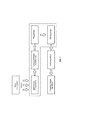
На фиг.1 показана структурно функциональная схема автономного самозаряжающегося источника питания, на которой показаны: тело человека, тепловая энергия выделяемая им, тепловой двигатель Стирлинга, передаточный механизм, редуктор, генератор, аккумулятор, электронный прибор где пунктиром показан функциональный блок автономного самозаряжающегося источника питания.Figure 1 shows a structurally functional diagram of an autonomous self-recharging power source, which shows: the human body, the thermal energy emitted by it, the Stirling heat engine, transmission mechanism, gearbox, generator, battery, electronic device, where the dotted line shows the functional unit of an autonomous self-recharging power source.
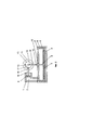
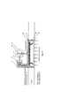
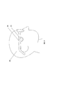
На фиг.2 показана конструкция теплового двигателя Стирлинга гамма типа в возможной компоновке для использования в автономном самозаряжающимся источнике питания, на которой показаны: рабочий цилиндр 1, внутренняя область рабочего цилиндра 2, поршень рабочего цилиндра 3, нагреватель-теплосъемник 4, охладитель 5, теплообменный цилиндр 6, дисплейсер-вытеснитель 7, стенки теплообменного цилиндра 8, шток дисплейсера 9, втулка охладителя 10, маховик 11, кривошипный шарнир поршня теплообменника 12, кривошипный шарнир рабочего поршня 13, кривошипный шарнир теплообменного цилиндра 14, кривошип 15, шатун дисплейсера 16, шатун рабочего цилиндра 17, шарнир оси рабочего поршня 18, шток рабочего поршня 19.Figure 2 shows the design of the gamma-type Stirling heat engine in a possible layout for use in a stand-alone self-recharging power source, which shows: the working
На фиг.3 показан 1-й такт работы двигателя Стирлинга гамма типа - такт сжатия рабочего тела при постоянной температуре: дисплейсер 7 находится вблизи нижней мертвой точки (НМТ) и остается условно неподвижным. Рабочее тело (газ) сжимается рабочим поршнем 3 малого цилиндра 1. Давление рабочего тела (газа) возрастает, а температура остается постоянной, так как теплота сжатия отводится через холодный торец теплообменного цилиндра 5 в окружающую среду. Белыми стрелками показано охлажденное рабочее тело, сжимаемое рабочим поршнем.Figure 3 shows the 1st cycle of the Stirling gamma-type engine - the compression cycle of the working fluid at a constant temperature: the
Под условной неподвижностью в данном случае подразумевают малую высоту перемещения поршня при прохождении кривошипом расстояния вблизи верхней или нижней мертвой точки.In this case, by conditional immobility is meant a small height of movement of the piston when the crank passes a distance near the top or bottom dead center.
На фиг.4 показан 2-й такт работы двигателя Стирлинга гамма типа - такт нагревания рабочего тела при постоянном объеме: рабочий поршень 3 рабочего цилиндра 1 находится вблизи НМТ и полностью перемещает охлажденное сжатое рабочее тело (газ) в теплообменный цилиндр 6, вытеснитель 7 которого движется к верхней мертвой точки (ВМТ) и вытесняет газ в горячую полость. Так как при этом суммарный внутренний объем цилиндров двигателя остается постоянным, рабочее тело разогревается, давление повышается и достигает максимального значения. Прирост давления идет параллельно с выталкиванием рабочего поршня 3. В результате давление не достигает теоретически рассчитанного максимума. Данный факт также объясняет хороший к.п.д. на малых оборотах двигателя. Рабочее тело прогревается лучше и прирост давления приближается к максимуму. Белыми стрелками показано охлажденное рабочее тело, сжимаемое рабочим поршнем, черно-белыми стрелками показано рабочее тело (газ), вытесняемое дисплейсером-вытеснителем из верхней холодной области в нижнюю горячую, где оно нагревается и расширяется.Figure 4 shows the 2nd cycle of operation of the gamma-type Stirling engine - the cycle of heating the working fluid with a constant volume: the working
На фиг.5 показан третий такт работы двигателя Стирлинга гамма типа - такт расширения при постоянной температуре газа: дисплейсер 7 теплообменного цилиндра 6 находится вблизи верхней мертвой точки (ВМТ) и остается условно неподвижным. Поршень рабочего цилиндра 3 под действием давления газа движется к верхней мертвой точке. Происходит расширение горячего рабочего тела (газа) в полости рабочего цилиндра 1. Полезная работа, совершаемая поршнем рабочего цилиндра 3, через кривошипно-шатунный механизм передается на кривошип 14 и маховик 11. Черными стрелками показано нагретое рабочее тело (газ). Давление в цилиндрах двигателя при этом падает, а температура газа в горячей полости остается постоянной, так как к нему подводится тепло от источника тепла через горячую стенку цилиндра.Figure 5 shows the third cycle of the gamma-type Stirling engine - expansion cycle at a constant gas temperature: the
На фиг.6 показан четвертый такт работы двигателя Стирлинга гамма типа - такт охлаждения при неизменном объеме: поршень рабочего цилиндра 3 находится вблизи ВМТ и остается условно неподвижным. Дисплейсер 7 теплообменного цилиндра движется к НМТ и перемещает рабочее тело (газ), оставшийся в горячей части в холодную часть цилиндра. Так как при этом суммарный внутренний объем цилиндров двигателя остается постоянным, давление газа в них продолжает падать и достигает минимального значения. В моделях двигателей, содержащих рабочее тело при атмосферном давлении четвертый такт также является рабочим, поскольку давление падает резко и возникает кратковременное разряжение. В результате рабочий поршень 3 с усилием втягивается в цилиндр 1, совершая дополнительную работу.Figure 6 shows the fourth cycle of the Stirling engine of the gamma type - cooling cycle at a constant volume: the piston of the working
Черно-белыми стрелками показано перемещение рабочего тела (газа), вытесняемое дисплейсером-вытеснителем, из нижней горячей области в верхнюю холодную, где оно охлаждается и сжимается. Из четырех тактов два - рабочие.Black and white arrows show the movement of the working fluid (gas) displaced by the displacer-displacer from the lower hot region to the upper cold region, where it is cooled and compressed. Of the four measures, two are workers.
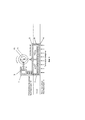
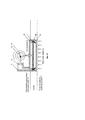
На фиг.7 показана конструкция автономного самозаряжающегося источника питания работающего от разности температур относительно человеческого тела и окружающего пространства, на котором показано: нагреватель-теплосъемник 4, который нагревается от тепла тела человека, охладитель 5, который контактирует с окружающей средой, стенки теплообменного цилиндра 8, передаточный механизм 20, редуктор 21, генератор 22, механический аккумулятор 23, химический аккумулятор 24.Figure 7 shows the design of an autonomous self-charging power source operating from a temperature difference relative to the human body and the surrounding space, which shows: a heater-
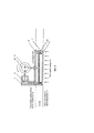
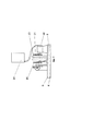
На фиг.8 показана конструкция электронного прибора, работающего от автономного самозаряжающегося источника питания, выполненного в виде наручного компьютера (умные часы), на котором показано: нагреватель-теплосъемник 4, который нагревается от тепла тела человека, охладитель 5, который контактирует с окружающей средой, стенки теплообменного цилиндра 8, генератор 22, аккумулятор 24, электронное устройство 26, экран электронного устройства 27, корпус электронного устройства 28, часть тела человека 29, фиксирующий ремень 30, охладительные каналы 31.On Fig shows the design of an electronic device that runs on a stand-alone self-recharging power source, made in the form of a wrist computer (smart watch), which shows: heater-
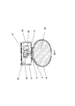
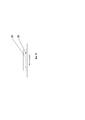
На фиг.9 показана конструкция электронного прибора, работающего от автономного самозаряжающегося источника питания, выполненного в виде электронных очков, на котором показано: автономный самозаряжающийся источник питания 25, корпус электронного устройства 28, часть тела человека 29.Figure 9 shows the design of an electronic device operating from an autonomous self-recharging power source made in the form of electronic glasses, which shows: an autonomous self-recharging
На фиг.10 показана конструкция электронного прибора, работающего от автономного самозаряжающегося источника питания, выполненного в чипа, на котором показано: автономный самозаряжающийся источник питания 25, электронное устройство 26.Figure 10 shows the design of an electronic device operating from a stand-alone self-recharging power source made in a chip, which shows: a stand-alone self-recharging
Осуществление изобретения.The implementation of the invention.
Изобретение представляет собою автономный самозаряжающийся источник питания для электронных устройств, носимых на теле человека при эксплуатации.The invention is an autonomous self-charging power source for electronic devices worn on the human body during operation.
Любое электронное устройство для функционирования использует электрический ток. Согласно изобретению функционирование электронного устройства осуществляется за счет самозаряжающегося источника питания, самозарядка которого происходит за счет разности температур и является абсолютно автономным процессом. Принцип работы изобретения основан на поэтапном преобразовании энергии, в частности преобразовании тепловой энергии, вырабатываемой человеческим телом, в механическую, а механической в электрическую. Для применения тепловой энергии, вырабатываемой человеческим телом, и перевода ее в механическую используется тепловой двигатель Стирлинга.Any electronic device uses electric current to function. According to the invention, the operation of the electronic device is carried out due to a self-recharging power source, which self-charges due to the temperature difference and is an absolutely autonomous process. The principle of operation of the invention is based on the phased conversion of energy, in particular the conversion of thermal energy produced by the human body into mechanical, and mechanical into electrical. To use the thermal energy generated by the human body, and translate it into mechanical, the Stirling heat engine is used.
В основе конструкции двигательной установки Стирлинга лежат принцип попеременного нагрева и охлаждения заключенного в изолированном пространстве рабочего тела, при котором работа, затрачиваемая на сжатие рабочего тела, меньше работы, возникающей при расширении рабочего тела, за счет чего вырабатывается полезная механическая энергия.The design of the Stirling propulsion system is based on the principle of alternately heating and cooling a working fluid enclosed in an isolated space, in which the work involved in compressing the working fluid is less than the work that occurs when the working fluid expands, due to which useful mechanical energy is generated.
Основные термодинамические процессы, протекающие в обычных тепловых двигателях: сжатие газа, поглощение тепла, расширение газа и отвод тепла, легко различимы и в цикле двигателя Стирлинга, однако имеется радикальное различие в том, как протекает процесс поглощения тепла в двигателе внутреннего сгорания (ДВС).The main thermodynamic processes that occur in conventional heat engines: gas compression, heat absorption, gas expansion and heat removal, are also easily distinguishable in the Stirling engine cycle, however, there is a radical difference in how the process of heat absorption occurs in an internal combustion engine (ICE).
В ДВС распыленное топливо соединяется с окислителем, как правило воздухом, до фазы сжатия или после этой фазы, и образовавшаяся горючая смесь отдает свою энергию во время кратковременной фазы горения (сгорания), в то время как в двигателе Стирлинга энергия поступает в двигатель и отводится от него через стенки цилиндра или теплообменник (см. фиг.3-6). Еще одним существенным различием является отсутствие клапанов или отверстий для впуска и выпуска, поскольку рабочее тело (газ) постоянно находится в полостях двигателя. Надо отметить, что скорость двигателя Стирлинга можно регулировать, изменяя количество газа в двигателе или величину среднего давления.In an internal combustion engine, the atomized fuel combines with the oxidizing agent, usually by air, before the compression phase or after this phase, and the resulting combustible mixture gives off its energy during the short-term phase of combustion (combustion), while in the Stirling engine the energy enters the engine and is removed from him through the walls of the cylinder or heat exchanger (see Fig.3-6). Another significant difference is the lack of valves or openings for inlet and outlet, since the working fluid (gas) is constantly located in the cavities of the engine. It should be noted that the speed of the Stirling engine can be adjusted by changing the amount of gas in the engine or the value of the average pressure.
Тепловой двигатель Стирлинга может работать не только от сжигания топлива, но и практически от любого источника тепла [7]. В моделях двигателей Стирлинга, где теплообменный цилиндр не имеет качественного нагревателя рабочее тело разогревается не полностью, но поскольку давление в газах распространяется равномерно во все стороны его изменение оказывает действие и на рабочий поршень, заставляя его двигаться и совершать работу.The Stirling heat engine can operate not only from fuel combustion, but also from virtually any heat source [7]. In models of Stirling engines, where the heat exchange cylinder does not have a high-quality heater, the working fluid is not fully heated, but since the pressure in the gases spreads uniformly in all directions, its change affects the working piston, forcing it to move and do the job.
В двигателях Стирлинга также могут применяться регенеративные теплообменники (регенераторы), размещенные в каналах, по которым газ перемещается между горячей и холодной зонами двигательной установки. Функцией регенератора является попеременное накопление и возвращение части тепловой энергии, полученной в рабочем цикле двигателя. Передача энергии пульсирующему газовому потоку должна происходить таким образом, чтобы свести к минимуму подвод тепла к установке и в то же время поддерживать на заданном уровне мощность, снимаемую с вала. Результатом действия регенератора является возрастание КПД цикла, и теплообменник такого типа может являться существенным элементом любого двигателя Стирлинга, рассчитанного на практическое применение. Таким образом, правильнее определить двигатель Стирлинга как тепловой двигатель, работающий по замкнутому регенеративному циклу.In Stirling engines, regenerative heat exchangers (regenerators) placed in channels through which gas moves between the hot and cold zones of the propulsion system can also be used. The function of the regenerator is to alternately accumulate and return part of the thermal energy received in the engine’s duty cycle. The energy transfer to the pulsating gas flow should take place in such a way as to minimize the supply of heat to the installation and at the same time maintain at a given level the power removed from the shaft. The result of the action of the regenerator is an increase in the efficiency of the cycle, and a heat exchanger of this type can be an essential element of any Stirling engine designed for practical use. Thus, it is more correct to define the Stirling engine as a heat engine operating in a closed regenerative cycle.
Также необходимо отметить, что заявляемая конструкция двигателя Стирлинга, функционирующего от тепла чела человека, предусматривает его работу и в случае, когда температура окружающей среды будет превышать температуру тела человека. В этом случае охладитель будет выполнять роль нагревателя, а нагреватель будет выполнять роль охладителя двигатель. Возникшая температурная разница будет по-прежнему заставлять сжиматься и разжиматься рабочее тело, которое в свою очередь будет приводить в движение вытеснитель-дисплейсер и рабочий поршень. При этом полезная работа, совершаемая рабочим поршнем, при помощи передаточного механизма передается на вращательный вал редуктора, который в свою очередь вращает вал генератора.It should also be noted that the claimed design of the Stirling engine, functioning from the heat of a person’s forehead, provides for its operation in the case when the ambient temperature will exceed the temperature of the human body. In this case, the cooler will act as a heater, and the heater will act as an engine cooler. The resulting temperature difference will still force the working fluid to compress and expand, which in turn will drive the displacer-dispenser and the working piston. At the same time, the useful work performed by the working piston is transmitted to the rotary shaft of the gearbox by the transmission mechanism, which in turn rotates the generator shaft.
Кроме этого, особенностью заявляемого устройства является и то, что нагреватель-теплосъемник (4) теплообменного цилиндра (6) может неплотно контактировать с телом человека, т.е. не предусматривается плотного контакта нагревателя с телом человека. Нагрев теплосъемника (4) осуществляется даже в случае его контакта с телом человека через одежду, например, через рубашку, тонкий свитер и пр., либо через плотный волосяной покров (волосы). В этом случае также будет осуществляться теплопередача и разогрев рабочего тела внутри теплообменного цилиндра (6).In addition, a feature of the claimed device is the fact that the heater-heat sink (4) of the heat exchange cylinder (6) can loosely contact the human body, i.e. tight contact of the heater with the human body is not provided. The heat sink (4) is heated even in case of contact with the human body through clothes, for example, through a shirt, a thin sweater, etc., or through a dense hair cover (hair). In this case, heat transfer and heating of the working fluid inside the heat exchange cylinder (6) will also take place.
Важное условие это то, что нагреватель-теплоприемник не должен контактировать с поверхностью тела контактирующего с охладителем, т.е. между этими поверхностями не должно быть никакого контакта. Для этого они должны быть разделены материалом с очень низкой теплопроводностью для предотвращения теплообмена и выравнивания температуры между нагревающей и охлаждающей поверхностями. Таким материалом может быть, например композит, пластмасса и т.д.An important condition is that the heater-heat sink should not be in contact with the surface of the body in contact with the cooler, i.e. there should not be any contact between these surfaces. To do this, they must be separated by a material with very low thermal conductivity to prevent heat transfer and equalization of temperature between the heating and cooling surfaces. Such material may be, for example, composite, plastic, etc.
В качестве теплового двигателя, в частности, может быть использован тепловой двигатель Стирлинга типа гамма. Он прост в изготовлении, низкотемпературный, низкооборотистый и, как показывают результаты многочисленных опытов, может работать на малом градиенте температур от 0,5-1,5 градуса Цельсия.As a heat engine, in particular, a gamma-type Stirling heat engine can be used. It is easy to manufacture, low temperature, low speed and, as shown by the results of numerous experiments, can operate on a small temperature gradient from 0.5-1.5 degrees Celsius.
Двигатель Стирлинга типа гамма состоит из двух цилиндров (см. фиг.2).The gamma-type Stirling engine consists of two cylinders (see figure 2).
Большой цилиндр - это теплообменный цилиндр 6. Его задача поочередно разогревать и охлаждать рабочее тело. Для этого один торец цилиндра разогревают - это нагреватель 4, другой торец - охлаждают - это охладитель 5. Боковые стенки теплообменного цилиндра 8 выполнены из материала с низкой теплопроводностью. Большой поршень - дисплейсер-вытеснитель 7 выполненный из теплоизоляционного материала, свободно перемещается в теплообменном цилиндре и выполняет роль теплового клапана, перегоняющего рабочее тело то к холодному, то к горячему торцу теплообменного цилиндра 6. Дисплейсер-вытеснитель может быть выполнен из композиционных материалов, пластмасс, эластомеров и.т.д.A large cylinder is a heat-
Малый цилиндр 1 является рабочим. Поршень рабочего цилиндра 3 плотно подогнан к рабочему цилиндру 1. Поршень рабочего цилиндра может быть выполнен из графита, композитных материалов, металлов и т.д.
Поршень рабочего цилиндра 3 имеет шток 19, который через шарнир 18, соединен с шатуном 17, соединенным через шарнир 13 с кривошипом 15.The piston of the working
В свою очередь дисплейсер-вытеснитель 7 имеет шток 9, который через шарнир 12, соединен с шатуном дисплейсера 16, соединенным через шарнир 14 с кривошипом 15.In turn, the displacer-
Шток 19, шарнир 18, шатун 17, шарнир 13, шток 9, шарнир 12, шатун 16, шарнир 14 кривошип 15 - представляют собой кривошипно-шатунный механизм, предназначенный для преобразования возвратно-поступательного движения поршней 3 и дисплейсера-вытеснителя 7 во вращательное движение кривошипа 15.The
Кривошип 15 кинематически, (на схеме соосно), соединен с маховиком 11. Маховик 11 предназначен для выравнивания движения и преодоления мертвых положений поршня и дисплейсера.The crank 15 kinematically, (in the diagram coaxially), is connected to the
Двигатель Стирлинга гамма типа работает следующим образом:The gamma-type Stirling engine operates as follows:
Цикл Стирлинга основан на последовательном нагревании и охлаждении газа (рабочего тела) в замкнутом объеме. Рабочее тело нагревается в горячей части двигателя, расширяется и производит полезную работу, после чего перегоняется в холодную часть двигателя где охлаждается, сжимается и снова подается в горячую часть двигателя. Цикл повторяется. Количество рабочего тела остается неизменным, меняется его температура, давление и объем.The Stirling cycle is based on the sequential heating and cooling of a gas (working fluid) in a closed volume. The working fluid is heated in the hot part of the engine, expands and does useful work, after which it is distilled to the cold part of the engine where it is cooled, compressed and again fed into the hot part of the engine. The cycle repeats. The amount of working fluid remains unchanged, its temperature, pressure and volume change.
Изменения объема в этих двух полостях не должны совпадать по фазе, а получившиеся в результате циклические изменения суммарного объема в свою очередь не должны совпадать по фазе с циклическим изменением давления.Volume changes in these two cavities should not coincide in phase, and the resulting cyclic changes in the total volume in turn should not coincide in phase with the cyclic pressure change.
Весь цикл условно разделен на четыре такта (фиг.3-6). Условность заключается в том, что четкое разделение на такты в цикле отсутствует, процессы переходят один в другой. Это обусловлено отсутствием в конструкции двигателей Стирлинга клапанного механизма. Особенности функционирования двигателя Стирлинга в конкретных тактах движения показаны на фиг.3-6.The whole cycle is conditionally divided into four measures (Fig.3-6). The convention is that there is no clear division into clock cycles in the cycle, the processes go one into the other. This is due to the lack of a valve mechanism in the design of Stirling engines. Features of the operation of the Stirling engine in specific clock cycles are shown in Fig.3-6.
Кроме двигателя Стирлинга типа гамма могут быть также использованы двигатели Стирлинга свободно поршневого типа и роторного типа, известные из уровня техники [7].In addition to the gamma-type Stirling engine, free-piston and rotary-type Stirling engines known in the art [7] can also be used.
В двигателе Стирлинга свободно поршневого типа, известного как двигатель Била или двигатели Стирлинга альфа типа, есть три основных элемента: тяжелый рабочий поршень, легкий вытеснитель и цилиндр с уплотнениями на обоих концах, шток вытеснителя относительно большого диаметра проходит через рабочий поршень. Шток вытеснителя полый, с открытым торцом, так что внутренняя полость вытеснителя соединена (и фактически является ее частью) с полостью, расположенной ниже рабочего поршня, называемой буферной полостью. К рабочей полости относится часть цилиндра над рабочим поршнем, подразделяемая на полость сжатия - между рабочим поршнем и вытеснителем и полость расширения - над вытеснителем. Длинная узкая кольцевая щель между цилиндром и вытеснителем выполняет функцию регенератора между горячей полостью расширения и холодной полостью сжатия. Для полости расширения предусмотрен нагреватель, а для полости сжатия - холодильник.The free-piston type Stirling engine, known as the Beela engine or alpha-type Stirling engines, has three main elements: a heavy working piston, a light displacer and a cylinder with seals at both ends, a displacer rod of a relatively large diameter passes through the working piston. The displacer rod is hollow, with an open end, so that the internal cavity of the displacer is connected (and in fact is a part of it) with a cavity located below the working piston, called the buffer cavity. The working cavity includes the part of the cylinder above the working piston, divided into a compression cavity - between the working piston and the displacer, and an expansion cavity - above the displacer. A long narrow annular gap between the cylinder and the displacer acts as a regenerator between the hot expansion cavity and the cold compression cavity. A heater is provided for the expansion cavity, and a refrigerator for the compression cavity.
В данном двигателе используется один цилиндр, но с двумя поршнями - дисплейсером и рабочим поршнем, расположенными первый над вторым по оси цилиндра. Шток дисплейсера проходит через крышку рабочего поршня и внутри его штока. Для обеспечения герметичности используются сальники. С одного края к цилиндру подводят тепло, с другой - охлаждают. Стенки рабочего поршня плотно прилегают к цилиндру. Дисплейсер - напротив - свободно движется в рабочем цилиндре. Дисплейсер выполнен из материала, имеющего низкую теплоемкость и выполняет роль “теплового клапана”. Он перемещает рабочее тело из горячей полости цилиндра в холодную и обратно, препятствуя наступлению термодинамического равновесия переноса тепла в системе. Рабочее тело либо нагревается (дисплейсер при этом находится в нижней мертвой точке), либо охлаждается (дисплейсер - в верхней мертвой точке). За счет этого обеспечивается циклический перепад давления в системе, преобразуемый затем рабочим поршнем в полезную работу. Нерабочий объем минимизирован за счет размещения вытеснителя и рабочего поршня в одном цилиндре, что позволяет выиграть в мощности на единицу объема двигателя.This engine uses one cylinder, but with two pistons - a dispenser and a working piston, located first above the second along the axis of the cylinder. The dispenser rod passes through the cover of the working piston and inside its rod. To ensure tightness, seals are used. Heat is supplied to the cylinder from one end, and cooled from the other. The walls of the working piston fit snugly against the cylinder. Displacer - on the contrary - moves freely in the working cylinder. The display is made of a material having a low heat capacity and acts as a “heat valve”. It moves the working fluid from the hot cavity of the cylinder to the cold and vice versa, preventing the onset of thermodynamic equilibrium of heat transfer in the system. The working fluid either heats up (the dispenser is located at the bottom dead center) or is cooled (the dispenser is at the top dead center). Due to this, a cyclic pressure difference in the system is ensured, which is then converted by the working piston into useful work. The non-working volume is minimized by placing the displacer and the working piston in one cylinder, which allows you to win in power per unit volume of the engine.
В двигателе Стирлинга роторного типа, в отличие от классической схемы теплообменного цилиндра, где дисплейсер совершает возвратно-поступательные движения, функцию “теплового клапана” выполняет несимметричный ротор. Вращаясь по оси он поочередно перекрывает горячую и холодную зоны, вызывая нагрев и охлаждение рабочего тела. Роторные Стирлинги отличаются более компактными размерами и могут быть выполнены полностью герметичными. Для этого в корпусе двигателя размещают генератор, или выводят механический привод через магнитную муфту.In a rotary-type Stirling engine, in contrast to the classic heat-exchange cylinder scheme, where the dispenser performs reciprocating movements, the asymmetrical rotor performs the function of the “heat valve”. Rotating along the axis, it alternately overlaps the hot and cold zones, causing heating and cooling of the working fluid. Rotary Stirlings are more compact and can be made completely airtight. For this, a generator is placed in the engine housing, or a mechanical drive is driven out through a magnetic coupling.
Тепловой двигатель Стирлинга преобразовывает разницу температур в энергию механического движения, в частном случае во вращение маховика или выходного вала, сопряженного с передаточным механизмом.The Stirling heat engine converts the temperature difference into energy of mechanical motion, in particular in the rotation of the flywheel or the output shaft, coupled with the transmission mechanism.
Нагреватель-теплоприемник не должен контактировать с поверхностью тела контактирующего с охладителем, то есть они должны быть разделены материалом с очень низкой теплопроводностью, например композит, пластмасса и т.д., и между ними не должно быть никакого контакта.The heater-heater should not be in contact with the surface of the body in contact with the cooler, that is, they should be separated by a material with very low thermal conductivity, for example composite, plastic, etc., and there should be no contact between them.
Передаточный механизм служит для преобразования и передачи вращательного, возвратно-поступательного движения поступающего с двигателя Стирлинга во вращение. Для увеличения оборотов вращения используется повышающий редуктор, на вал которого передается вращение с передаточного механизма. Повышающий редуктор увеличивает угловую скорость и уменьшает крутящий момент.The transmission mechanism is used to convert and transmit rotational, reciprocating motion coming from the Stirling engine into rotation. To increase the revolutions of rotation, a step-up gearbox is used, on the shaft of which rotation is transmitted from the transmission mechanism. The step-up gear increases the angular velocity and reduces the torque.
Для перевода механической энергии в электрическую, вращение с редуктора передается на вал генератора, принцип действия которого основан на явлении электромагнитной индукции, когда в проводнике, двигающемся в магнитном поле и пересекающем его магнитные силовые линии, индуктируется электродвижущая сила.To convert mechanical energy into electrical energy, rotation from the gearbox is transmitted to the generator shaft, the principle of which is based on the phenomenon of electromagnetic induction, when an electromotive force is induced in a conductor moving in a magnetic field and crossing magnetic field lines.
Электроэнергия вырабатываемая генератором передается на аккумулятор и постоянного его подзаряжает/заряжает. В качестве химического аккумулятора могут применяться любые химические аккумуляторы отвечающие такому требованию как стойкость к перезарядке, к частой подзарядке и возможность заряжаться от малого напряжения, например литий-ионные, никель-металл-гидридные и т.п.The electricity generated by the generator is transferred to the battery and constantly recharges / charges it. As a chemical accumulator, any chemical accumulators that meet such a requirement as resistance to overcharging, frequent recharging and the ability to charge from a low voltage, for example lithium-ion, nickel-metal hydride, etc., can be used.
В некоторых вариантах автономного самозаряжающегося источника питания, при временном отсутствии работы двигателя Стирлинга, вызванного временным отсутствием разности температур, возможно применение механического аккумулятора в узле между передаточным механизмом и редуктором. Принцип работы механического аккумулятора основан на сохранении энергии механическими средствами, такими как спиральная пружина, пружина, груз, маятник и т.п. Механический аккумулятор представляет собой спиральную пружину, которая закручивается при вращении вала от передаточного механизма, который в свою очередь приводится в движение тепловым двигателем Стирлинга. Механический аккумулятор оснащен защитой пружиной, которая защищает ее от перекручивания, что может привести к разрыву пружины, то есть при достижении определенного напряжения при закручивании происходит прокрутка пружины.In some versions of an autonomous self-recharging power source, in the case of a temporary absence of the Stirling engine operation caused by a temporary absence of a temperature difference, it is possible to use a mechanical battery in the assembly between the transmission mechanism and the gearbox. The principle of operation of a mechanical battery is based on the conservation of energy by mechanical means, such as a coil spring, spring, load, pendulum, etc. The mechanical accumulator is a spiral spring, which is twisted when the shaft rotates from the transmission mechanism, which in turn is driven by the Stirling heat engine. The mechanical battery is equipped with a spring protection, which protects it from twisting, which can lead to a spring break, that is, when a certain voltage is reached during twisting, the spring scrolls.
Помимо механического аккумулятора, работающего от пружины, возможно применение аккумулятора гидравлического, пневматического, гиревого или маховичного.In addition to a mechanical spring-powered battery, a hydraulic, pneumatic, weight-lifting or flywheel battery is also possible.
Возможна работа изобретения прямой подачей вращения с передаточного механизма на генератор.The invention can be operated by direct feed of rotation from the transmission mechanism to the generator.
Возможна работа изобретения с прямой подачей возвратно-поступательного движения на генератор работающего от возвратно-поступательного движения.Possible operation of the invention with direct feed back and forth motion to a generator operating from reciprocating motion.
Возможно выполнение автономного самозаряжающегося источника питания для электронных приборов, контактирующих с телом человека, как непосредственно составляющий объект прибора, так и отдельное самостоятельное зарядное устройство.It is possible to perform an autonomous self-recharging power source for electronic devices in contact with the human body, either directly constituting the device's object or a separate independent charger.
Возможна реализация устройства таким образом, что вместо генератора электрического тока механическое воздействие от двигателя Стирлинга подается напрямую на аккумуляторы, которые непосредственно преобразуют механическую энергию в химическую, то есть на аккумуляторы электрической энергии, заряжаемые механическим путем.It is possible to implement the device in such a way that instead of an electric current generator, the mechanical effect from the Stirling engine is supplied directly to the batteries, which directly convert mechanical energy into chemical energy, that is, to electric energy batteries that are charged mechanically.
Возможно оснащение автономного самозаряжающегося источника питания дополнительным, вспомогательным теплоприемным материалом для лучшего сбора тепловой энергии от тела человека.It is possible to equip an autonomous self-recharging power source with additional, auxiliary heat-receiving material for better collection of thermal energy from the human body.
Электронный прибор должен быть носимым на теле человека и может быть базовым, серийно выпускаемым, как в стандартном исполнении, так и с дополнительной доработкой. Это может быть, в частности, коммуникатор либо смартфон, либо так называемые «умные часы», выполненные в виде компьютера и которые можно носить на руке, пристегнув обычным браслетом от часов. Также в качестве носимого электронного прибора используются очки со встроенным компьютером, которые могут показывать время, температуру воздуха и использоваться как GPS навигатор и т.д. Также устройство, которое возможно носить на теле может быть выполнено в виде микрочипа, датчика и т.д.An electronic device must be wearable on the human body and can be basic, commercially available, both in standard design and with additional refinement. This can be, in particular, a communicator or a smartphone, or the so-called “smart watch”, made in the form of a computer and which can be worn on the hand, fastened with a regular bracelet from the watch. Also, glasses with a built-in computer are used as a portable electronic device, which can show time, air temperature and can be used as a GPS navigator, etc. Also, a device that can be worn on the body can be made in the form of a microchip, sensor, etc.
Все перечисленные устройства приведены здесь в качестве примера использования автономного самозаряжающегося источника питания и ни в коей мере не ограничивают область его применения.All of the listed devices are given here as an example of using an autonomous self-recharging power source and in no way limit the scope of its application.
Автономный самозаряжающийся источник питания может быть выполнен как внутри электронного прибора, носимого на теле, так и на его поверхности.Autonomous self-charging power source can be made both inside the electronic device worn on the body and on its surface.
Принцип работы автономного самозаряжающегося источника питания электронного устройства, контактирующего с телом человека, заключается в следующем: поступательно-вращательное движение, получаемое от двигателя Стирлинга, через передаточный механизм преобразуется во вращение вала редуктора.The principle of operation of an autonomous self-charging power source of an electronic device in contact with the human body is as follows: the translational-rotational movement received from the Stirling engine, through the transmission mechanism, is converted into rotation of the gearbox shaft.
С редуктора вращение передается генератору, который при вращении вырабатывает электроэнергию.From the gearbox, the rotation is transmitted to the generator, which generates electricity during rotation.
Получаемая электроэнергия с генератора подается на химический аккумулятор.Received electricity from the generator is fed to a chemical battery.
Таким образом обеспечивается достижение требуемого технического результата, а именно достигается технический результат, который заключается в получении электрического тока и накопление электрической энергии для постоянной автономной самозарядки источника питания для электронных приборов, контактирующих с человеческим телом, посредством преобразования тепловой энергии вырабатываемой человеческим телом, т.е. использования разности температур относительно тела человека и окружающего пространства. Кроме этого достигается технический результат, который заключается в увеличении автономности работы носимого на теле человека электронного устройства, которое достигается за счет обеспечения бесперебойного, постоянного стабильного напряжения питания, которое в свою очередь достигается при использовании автономного самозаряжающегося источника питания, использующего тепловую энергию, выделяемую телом человека для функционирования теплового двигателя Стирлинга и последующей передачей механической энергии на генератор, который вырабатывает электрический ток и в свою очередь заряжает аккумулятор. Также обеспечивается существенное увеличение времени работы устройства без использования внешних источников электрической энергии (электрическая сеть), т.е. при эксплуатации электронное устройство практически не нуждается в подзарядке от внешних стандартных источников питания. Кроме этого повышается надежность и долговечность работы электронного устройства, контактирующего с телом человека при использовании автономного самозаряжающегося источника питания, за счет исключения полной разрядки аккумулятора.This ensures the achievement of the required technical result, namely, the technical result is achieved, which consists in obtaining electric current and the accumulation of electric energy for constant autonomous self-charging of the power source for electronic devices in contact with the human body, by converting the thermal energy generated by the human body, i.e. . using the temperature difference relative to the human body and the surrounding space. In addition, a technical result is achieved, which consists in increasing the autonomy of the electronic device worn on the human body, which is achieved by providing an uninterrupted, constant stable voltage, which, in turn, is achieved by using an autonomous self-recharging power source that uses thermal energy released by the human body for the functioning of the Stirling heat engine and the subsequent transfer of mechanical energy to a generator that abates electric current and in turn charges the battery. It also provides a significant increase in the operating time of the device without the use of external sources of electrical energy (electrical network), i.e. during operation, the electronic device practically does not need recharging from external standard power sources. In addition, the reliability and longevity of the electronic device in contact with the human body when using an autonomous self-recharging power source is increased, due to the exclusion of the complete discharge of the battery.
Учитывая новизну совокупности существенных признаков, техническую осуществимость и промышленную применимость изобретения, решение поставленных изобретательских задач и уверенное достижение требуемого технического результата при реализации и использовании изобретения, по нашему мнению, заявленная группа изобретений удовлетворяет всем требованиям охраноспособности, предъявляемым к изобретениям.Given the novelty of the set of essential features, the technical feasibility and industrial applicability of the invention, the solution of the set inventive problems and the confident achievement of the required technical result when implementing and using the invention, in our opinion, the claimed group of inventions satisfies all the eligibility requirements for inventions.
Проведенный анализ показывает также, что все общие и частные признаки изобретения являются существенными, так как каждый из них необходим, а все вместе они не только достаточны для достижения цели изобретения, но и позволяют реализовать изобретение промышленным способом.The analysis also shows that all the general and particular features of the invention are essential, since each of them is necessary, and all together they are not only sufficient to achieve the purpose of the invention, but also make it possible to realize the invention in an industrial way.
ИСТОЧНИКИ ИНФОРМАЦИИINFORMATION SOURCES
1. Ju Y, Maruta K, Microscale combustion: Technology development and fundamental research, Progress in Energy and Combustion Science (2011), doi:10.1016/j.pecs.2011.03.001, p.1-47.1. Ju Y, Maruta K, Microscale combustion: Technology development and fundamental research, Progress in Energy and Combustion Science (2011), doi: 10.1016 / j.pecs.2011.03.001, p.1-47.
2. http://www.membrana.ru/particle/99812.http: //www.membrana.ru/particle/9981
3. Т.И. Трофимова. Курс физики: учебное пособие для вузов. 11-е изд., степр. - М.: Издательский центр «академия», 2006. Стр.465-467.3. T.I. Trofimova. Physics course: textbook for universities. 11th ed. - M.: Publishing Center "Academy", 2006. P. 465-467.
4. R.A. Segalman, (510) 642-7998 and A. Majumdar (510) 643-8199, Materials Sciences Division (510) 486-4755, Berkeley Lab. Pramod Reddy, Sung-Yeon Jang, Rachel Segalman and Arun Majumdar, “Thermoelectricity in Molecular Junctions,” Science 315, 1568 (2007).4. R.A. Segalman, (510) 642-7998 and A. Majumdar (510) 643-8199, Materials Sciences Division (510) 486-4755, Berkeley Lab. Pramod Reddy, Sung-Yeon Jang, Rachel Segalman and Arun Majumdar, “Thermoelectricity in Molecular Junctions,” Science 315, 1568 (2007).
5. CN 202425613 U, SIYE LU, опубл. 12.09.2012.5. CN 202425613 U, SIYE LU, publ. 09/12/2012.
6. RU 2494523 C2, Милашенко А.Ф., опубл. 27.09.2013.6. RU 2494523 C2, A. Milashenko, publ. 09/27/2013.
7. Уокер Г. Машины, работающие по циклу Стирлинга. пер. с англ. М. Энергия 1978 г.7. Walker G. Stirling cycle machines. trans. from English M. Energy 1978
Claims (35)
Priority Applications (1)
| Application Number | Priority Date | Filing Date | Title |
|---|---|---|---|
| RU2013147931A RU2617543C2 (en) | 2013-10-29 | 2013-10-29 | Method of production and accumulation of electric power from human body, autonomous self-responsible power source and electronic device worn on human body |
Applications Claiming Priority (1)
| Application Number | Priority Date | Filing Date | Title |
|---|---|---|---|
| RU2013147931A RU2617543C2 (en) | 2013-10-29 | 2013-10-29 | Method of production and accumulation of electric power from human body, autonomous self-responsible power source and electronic device worn on human body |
Publications (2)
| Publication Number | Publication Date |
|---|---|
| RU2013147931A RU2013147931A (en) | 2015-05-20 |
| RU2617543C2 true RU2617543C2 (en) | 2017-04-25 |
Family
ID=53283534
Family Applications (1)
| Application Number | Title | Priority Date | Filing Date |
|---|---|---|---|
| RU2013147931A RU2617543C2 (en) | 2013-10-29 | 2013-10-29 | Method of production and accumulation of electric power from human body, autonomous self-responsible power source and electronic device worn on human body |
Country Status (1)
| Country | Link |
|---|---|
| RU (1) | RU2617543C2 (en) |
Citations (7)
| Publication number | Priority date | Publication date | Assignee | Title |
|---|---|---|---|---|
| RU7146U1 (en) * | 1997-07-16 | 1998-07-16 | Валерий Петрович Каштанов | ENERGY INSTALLATION |
| RU96120040A (en) * | 1996-09-25 | 1998-12-10 | Н.Г. Кириллов | POWER INSTALLATION BASED ON THE STIRLING ENGINE TYPE "FLUIDAYN" |
| RU2002119220A (en) * | 2002-07-22 | 2004-01-20 | Немиро Вадим Борисович (UA) | WEARABLE RADIOTELEPHONE APPARATUS |
| JP2009156233A (en) * | 2007-12-27 | 2009-07-16 | Chubu Electric Power Co Inc | Stirling engine power generator |
| WO2011020988A2 (en) * | 2009-08-17 | 2011-02-24 | Isis Innovation Limited | Stirling cycle machine |
| CN202082003U (en) * | 2011-05-16 | 2011-12-21 | 南京航空航天大学 | Stirling low-temperature high-efficiency generating set |
| RU112535U1 (en) * | 2011-04-06 | 2012-01-10 | Борис Викторович Авдеев | UNIT FOR PRODUCING ELECTRICITY IN THE FIELD CONDITIONS |
-
2013
- 2013-10-29 RU RU2013147931A patent/RU2617543C2/en active
Patent Citations (8)
| Publication number | Priority date | Publication date | Assignee | Title |
|---|---|---|---|---|
| RU96120040A (en) * | 1996-09-25 | 1998-12-10 | Н.Г. Кириллов | POWER INSTALLATION BASED ON THE STIRLING ENGINE TYPE "FLUIDAYN" |
| RU7146U1 (en) * | 1997-07-16 | 1998-07-16 | Валерий Петрович Каштанов | ENERGY INSTALLATION |
| RU2172421C2 (en) * | 1999-11-01 | 2001-08-20 | Военный инженерно-космический университет им. А.Ф. Можайского | Self-contained combination power plant using stirling engine |
| RU2002119220A (en) * | 2002-07-22 | 2004-01-20 | Немиро Вадим Борисович (UA) | WEARABLE RADIOTELEPHONE APPARATUS |
| JP2009156233A (en) * | 2007-12-27 | 2009-07-16 | Chubu Electric Power Co Inc | Stirling engine power generator |
| WO2011020988A2 (en) * | 2009-08-17 | 2011-02-24 | Isis Innovation Limited | Stirling cycle machine |
| RU112535U1 (en) * | 2011-04-06 | 2012-01-10 | Борис Викторович Авдеев | UNIT FOR PRODUCING ELECTRICITY IN THE FIELD CONDITIONS |
| CN202082003U (en) * | 2011-05-16 | 2011-12-21 | 南京航空航天大学 | Stirling low-temperature high-efficiency generating set |
Non-Patent Citations (1)
| Title |
|---|
| http://physicstoys.narod.ru/page/Nizkotemperatyrnie.html 25.08.2009. * |
Also Published As
| Publication number | Publication date |
|---|---|
| RU2013147931A (en) | 2015-05-20 |
Similar Documents
| Publication | Publication Date | Title |
|---|---|---|
| Enescu | Thermoelectric energy harvesting: basic principles and applications | |
| Zabek et al. | Solid state generators and energy harvesters for waste heat recovery and thermal energy harvesting | |
| US7329959B2 (en) | Micro power generator and apparatus for producing reciprocating movement | |
| WO2003023871A3 (en) | Method for producing a device for direct thermoelectric energy conversion | |
| US9482450B2 (en) | Ericsson cycle device improvements | |
| Ding et al. | Performance analysis for an irreversible combined thermionic-thermoelectric generator with finite rate heat transfer | |
| CN106679216B (en) | A Rotary Integrated Stirling Refrigerator | |
| Harsito et al. | Investigation of sandwich-type generator thermoelectric element power generation | |
| CN109653898B (en) | Electric feedback opposed free piston Stirling generator | |
| RU142466U1 (en) | AUTONOMOUS SELF-CHARGING POWER SUPPLY AND PERSONAL WEARABLE ELECTRONIC DEVICE | |
| US10087883B2 (en) | Stirling engine with regenerator internal to the displacer piston and integral geometry for heat transfer and fluid flow | |
| Xia et al. | The optimal path of piston motion for Otto cycle with linear phenomenological heat transfer law | |
| RU2617543C2 (en) | Method of production and accumulation of electric power from human body, autonomous self-responsible power source and electronic device worn on human body | |
| CN106762211B (en) | A kind of stirling generator and electricity-generating method based on dielectric elastomer | |
| US3118285A (en) | Thermo- | |
| KR102063711B1 (en) | Triboelectric energy harvester using stirling engine | |
| CN104564416A (en) | Stirling engine employing star connecting rod transmission mode | |
| Chen et al. | A novel configuration and performance for a two-stage thermoelectric heat pump system driven by a two-stage thermoelectric generator | |
| Chen et al. | Effect of heat transfer on the performance of a thermoelectric heat pump driven by a thermoelectric generator | |
| Meng et al. | Multiobjective analyses of physical dimension on the performance of a TEG–TEC system | |
| JP2010255547A (en) | Vane rotary type heating and cooling device | |
| Assad | Thermodynamic analysis of MHD power cycle | |
| Chen et al. | Optimisation of a model internal combustion engine with linear phenomenological heat transfer law | |
| RU2013145458A (en) | ELECTRIC TIME INSTRUMENT, METHOD AND DEVICE FOR PRODUCING ELECTRIC POWER ACTING AN ELECTRICAL TIME INSTRUMENT | |
| RU137129U1 (en) | DEVICE FOR AUTOMATIC DRIVING OF THE HOUR MECHANISM, CLOCK MECHANISM CONTAINING DEVICE FOR AUTOMATIC DRIVING OF THE CLOCK MOVEMENT, MECHANICAL HOURS, INCLUDED, INCLUDED |