RU2615331C2 - Selective power amplifier - Google Patents
Selective power amplifier Download PDFInfo
- Publication number
- RU2615331C2 RU2615331C2 RU2014129827A RU2014129827A RU2615331C2 RU 2615331 C2 RU2615331 C2 RU 2615331C2 RU 2014129827 A RU2014129827 A RU 2014129827A RU 2014129827 A RU2014129827 A RU 2014129827A RU 2615331 C2 RU2615331 C2 RU 2615331C2
- Authority
- RU
- Russia
- Prior art keywords
- mode
- power amplifier
- transmission
- transmitter
- output
- Prior art date
Links
- 230000005540 biological transmission Effects 0.000 claims abstract description 77
- 238000004891 communication Methods 0.000 claims abstract description 26
- 238000000034 method Methods 0.000 claims description 38
- 238000005516 engineering process Methods 0.000 claims description 20
- 230000003595 spectral effect Effects 0.000 claims description 13
- 238000006243 chemical reaction Methods 0.000 claims description 12
- 230000002902 bimodal effect Effects 0.000 claims description 7
- 238000004590 computer program Methods 0.000 claims description 7
- 230000007246 mechanism Effects 0.000 claims description 7
- 230000010267 cellular communication Effects 0.000 claims description 5
- 230000000694 effects Effects 0.000 abstract description 5
- 239000000126 substance Substances 0.000 abstract 1
- 238000001228 spectrum Methods 0.000 description 13
- 230000000875 corresponding effect Effects 0.000 description 9
- 230000006870 function Effects 0.000 description 7
- 238000012545 processing Methods 0.000 description 6
- 230000001276 controlling effect Effects 0.000 description 4
- 230000008901 benefit Effects 0.000 description 3
- 238000012937 correction Methods 0.000 description 3
- 238000005265 energy consumption Methods 0.000 description 3
- 239000011159 matrix material Substances 0.000 description 3
- 230000009471 action Effects 0.000 description 2
- 230000008859 change Effects 0.000 description 2
- 238000010295 mobile communication Methods 0.000 description 2
- 238000001208 nuclear magnetic resonance pulse sequence Methods 0.000 description 2
- 230000010363 phase shift Effects 0.000 description 2
- 230000008569 process Effects 0.000 description 2
- 230000009466 transformation Effects 0.000 description 2
- 230000006978 adaptation Effects 0.000 description 1
- 230000003044 adaptive effect Effects 0.000 description 1
- 238000007792 addition Methods 0.000 description 1
- 238000013459 approach Methods 0.000 description 1
- 230000001413 cellular effect Effects 0.000 description 1
- 230000003247 decreasing effect Effects 0.000 description 1
- 230000003111 delayed effect Effects 0.000 description 1
- 230000001419 dependent effect Effects 0.000 description 1
- 230000002349 favourable effect Effects 0.000 description 1
- 238000009499 grossing Methods 0.000 description 1
- 238000003780 insertion Methods 0.000 description 1
- 230000037431 insertion Effects 0.000 description 1
- 238000012886 linear function Methods 0.000 description 1
- 230000000116 mitigating effect Effects 0.000 description 1
- 238000005457 optimization Methods 0.000 description 1
- PIRWNASAJNPKHT-SHZATDIYSA-N pamp Chemical group C([C@@H](C(=O)N[C@@H](CCCNC(N)=N)C(=O)N[C@@H](CCCCN)C(=O)N[C@@H](CCCCN)C(=O)N[C@@H](CC=1C2=CC=CC=C2NC=1)C(=O)N[C@@H](CC(N)=O)C(=O)N[C@@H](CCCCN)C(=O)N[C@@H](CC=1C2=CC=CC=C2NC=1)C(=O)N[C@@H](C)C(=O)N[C@@H](CC(C)C)C(=O)N[C@@H](CO)C(=O)N[C@@H](CCCNC(N)=N)C(N)=O)NC(=O)[C@H](CCC(O)=O)NC(=O)[C@H](CO)NC(=O)[C@H](C)NC(=O)[C@@H](NC(=O)[C@H](CC(O)=O)NC(=O)[C@H](CC(C)C)NC(=O)[C@H](CCCNC(N)=N)NC(=O)[C@H](C)N)C(C)C)C1=CC=CC=C1 PIRWNASAJNPKHT-SHZATDIYSA-N 0.000 description 1
- 230000008447 perception Effects 0.000 description 1
- 230000001105 regulatory effect Effects 0.000 description 1
- 238000005070 sampling Methods 0.000 description 1
- 239000004065 semiconductor Substances 0.000 description 1
- 230000001953 sensory effect Effects 0.000 description 1
Images
Classifications
-
- H—ELECTRICITY
- H04—ELECTRIC COMMUNICATION TECHNIQUE
- H04L—TRANSMISSION OF DIGITAL INFORMATION, e.g. TELEGRAPHIC COMMUNICATION
- H04L27/00—Modulated-carrier systems
- H04L27/0008—Modulated-carrier systems arrangements for allowing a transmitter or receiver to use more than one type of modulation
-
- H—ELECTRICITY
- H03—ELECTRONIC CIRCUITRY
- H03G—CONTROL OF AMPLIFICATION
- H03G5/00—Tone control or bandwidth control in amplifiers
- H03G5/16—Automatic control
- H03G5/24—Automatic control in frequency-selective amplifiers
- H03G5/28—Automatic control in frequency-selective amplifiers having semiconductor devices
-
- H—ELECTRICITY
- H03—ELECTRONIC CIRCUITRY
- H03F—AMPLIFIERS
- H03F1/00—Details of amplifiers with only discharge tubes, only semiconductor devices or only unspecified devices as amplifying elements
- H03F1/02—Modifications of amplifiers to raise the efficiency, e.g. gliding Class A stages, use of an auxiliary oscillation
- H03F1/0205—Modifications of amplifiers to raise the efficiency, e.g. gliding Class A stages, use of an auxiliary oscillation in transistor amplifiers
- H03F1/0211—Modifications of amplifiers to raise the efficiency, e.g. gliding Class A stages, use of an auxiliary oscillation in transistor amplifiers with control of the supply voltage or current
- H03F1/0216—Continuous control
- H03F1/0222—Continuous control by using a signal derived from the input signal
- H03F1/0227—Continuous control by using a signal derived from the input signal using supply converters
-
- H—ELECTRICITY
- H03—ELECTRONIC CIRCUITRY
- H03F—AMPLIFIERS
- H03F1/00—Details of amplifiers with only discharge tubes, only semiconductor devices or only unspecified devices as amplifying elements
- H03F1/32—Modifications of amplifiers to reduce non-linear distortion
- H03F1/3241—Modifications of amplifiers to reduce non-linear distortion using predistortion circuits
- H03F1/3282—Acting on the phase and the amplitude of the input signal
-
- H—ELECTRICITY
- H03—ELECTRONIC CIRCUITRY
- H03F—AMPLIFIERS
- H03F3/00—Amplifiers with only discharge tubes or only semiconductor devices as amplifying elements
- H03F3/189—High-frequency amplifiers, e.g. radio frequency amplifiers
- H03F3/19—High-frequency amplifiers, e.g. radio frequency amplifiers with semiconductor devices only
-
- H—ELECTRICITY
- H03—ELECTRONIC CIRCUITRY
- H03F—AMPLIFIERS
- H03F3/00—Amplifiers with only discharge tubes or only semiconductor devices as amplifying elements
- H03F3/20—Power amplifiers, e.g. Class B amplifiers, Class C amplifiers
- H03F3/21—Power amplifiers, e.g. Class B amplifiers, Class C amplifiers with semiconductor devices only
- H03F3/217—Class D power amplifiers; Switching amplifiers
-
- H—ELECTRICITY
- H03—ELECTRONIC CIRCUITRY
- H03F—AMPLIFIERS
- H03F3/00—Amplifiers with only discharge tubes or only semiconductor devices as amplifying elements
- H03F3/20—Power amplifiers, e.g. Class B amplifiers, Class C amplifiers
- H03F3/24—Power amplifiers, e.g. Class B amplifiers, Class C amplifiers of transmitter output stages
- H03F3/245—Power amplifiers, e.g. Class B amplifiers, Class C amplifiers of transmitter output stages with semiconductor devices only
-
- H—ELECTRICITY
- H04—ELECTRIC COMMUNICATION TECHNIQUE
- H04B—TRANSMISSION
- H04B1/00—Details of transmission systems, not covered by a single one of groups H04B3/00 - H04B13/00; Details of transmission systems not characterised by the medium used for transmission
- H04B1/02—Transmitters
- H04B1/04—Circuits
-
- H—ELECTRICITY
- H04—ELECTRIC COMMUNICATION TECHNIQUE
- H04B—TRANSMISSION
- H04B1/00—Details of transmission systems, not covered by a single one of groups H04B3/00 - H04B13/00; Details of transmission systems not characterised by the medium used for transmission
- H04B1/38—Transceivers, i.e. devices in which transmitter and receiver form a structural unit and in which at least one part is used for functions of transmitting and receiving
- H04B1/40—Circuits
- H04B1/403—Circuits using the same oscillator for generating both the transmitter frequency and the receiver local oscillator frequency
- H04B1/406—Circuits using the same oscillator for generating both the transmitter frequency and the receiver local oscillator frequency with more than one transmission mode, e.g. analog and digital modes
-
- H—ELECTRICITY
- H04—ELECTRIC COMMUNICATION TECHNIQUE
- H04J—MULTIPLEX COMMUNICATION
- H04J11/00—Orthogonal multiplex systems, e.g. using WALSH codes
-
- H—ELECTRICITY
- H04—ELECTRIC COMMUNICATION TECHNIQUE
- H04L—TRANSMISSION OF DIGITAL INFORMATION, e.g. TELEGRAPHIC COMMUNICATION
- H04L1/00—Arrangements for detecting or preventing errors in the information received
- H04L1/20—Arrangements for detecting or preventing errors in the information received using signal quality detector
- H04L1/203—Details of error rate determination, e.g. BER, FER or WER
-
- H—ELECTRICITY
- H04—ELECTRIC COMMUNICATION TECHNIQUE
- H04L—TRANSMISSION OF DIGITAL INFORMATION, e.g. TELEGRAPHIC COMMUNICATION
- H04L27/00—Modulated-carrier systems
- H04L27/32—Carrier systems characterised by combinations of two or more of the types covered by groups H04L27/02, H04L27/10, H04L27/18 or H04L27/26
- H04L27/34—Amplitude- and phase-modulated carrier systems, e.g. quadrature-amplitude modulated carrier systems
- H04L27/36—Modulator circuits; Transmitter circuits
- H04L27/362—Modulation using more than one carrier, e.g. with quadrature carriers, separately amplitude modulated
-
- H—ELECTRICITY
- H04—ELECTRIC COMMUNICATION TECHNIQUE
- H04L—TRANSMISSION OF DIGITAL INFORMATION, e.g. TELEGRAPHIC COMMUNICATION
- H04L43/00—Arrangements for monitoring or testing data switching networks
- H04L43/16—Threshold monitoring
-
- H—ELECTRICITY
- H04—ELECTRIC COMMUNICATION TECHNIQUE
- H04L—TRANSMISSION OF DIGITAL INFORMATION, e.g. TELEGRAPHIC COMMUNICATION
- H04L45/00—Routing or path finding of packets in data switching networks
- H04L45/74—Address processing for routing
- H04L45/745—Address table lookup; Address filtering
-
- H—ELECTRICITY
- H04—ELECTRIC COMMUNICATION TECHNIQUE
- H04W—WIRELESS COMMUNICATION NETWORKS
- H04W52/00—Power management, e.g. TPC [Transmission Power Control], power saving or power classes
- H04W52/02—Power saving arrangements
- H04W52/0209—Power saving arrangements in terminal devices
-
- H—ELECTRICITY
- H04—ELECTRIC COMMUNICATION TECHNIQUE
- H04W—WIRELESS COMMUNICATION NETWORKS
- H04W52/00—Power management, e.g. TPC [Transmission Power Control], power saving or power classes
- H04W52/04—TPC
- H04W52/52—TPC using AGC [Automatic Gain Control] circuits or amplifiers
-
- H—ELECTRICITY
- H04—ELECTRIC COMMUNICATION TECHNIQUE
- H04W—WIRELESS COMMUNICATION NETWORKS
- H04W72/00—Local resource management
- H04W72/04—Wireless resource allocation
- H04W72/044—Wireless resource allocation based on the type of the allocated resource
- H04W72/0453—Resources in frequency domain, e.g. a carrier in FDMA
-
- H—ELECTRICITY
- H04—ELECTRIC COMMUNICATION TECHNIQUE
- H04W—WIRELESS COMMUNICATION NETWORKS
- H04W72/00—Local resource management
- H04W72/04—Wireless resource allocation
- H04W72/044—Wireless resource allocation based on the type of the allocated resource
- H04W72/0473—Wireless resource allocation based on the type of the allocated resource the resource being transmission power
-
- H—ELECTRICITY
- H04—ELECTRIC COMMUNICATION TECHNIQUE
- H04W—WIRELESS COMMUNICATION NETWORKS
- H04W72/00—Local resource management
- H04W72/20—Control channels or signalling for resource management
- H04W72/21—Control channels or signalling for resource management in the uplink direction of a wireless link, i.e. towards the network
-
- H—ELECTRICITY
- H04—ELECTRIC COMMUNICATION TECHNIQUE
- H04W—WIRELESS COMMUNICATION NETWORKS
- H04W72/00—Local resource management
- H04W72/20—Control channels or signalling for resource management
- H04W72/23—Control channels or signalling for resource management in the downlink direction of a wireless link, i.e. towards a terminal
-
- H—ELECTRICITY
- H03—ELECTRONIC CIRCUITRY
- H03F—AMPLIFIERS
- H03F2200/00—Indexing scheme relating to amplifiers
- H03F2200/102—A non-specified detector of a signal envelope being used in an amplifying circuit
-
- H—ELECTRICITY
- H03—ELECTRONIC CIRCUITRY
- H03F—AMPLIFIERS
- H03F2200/00—Indexing scheme relating to amplifiers
- H03F2200/336—A I/Q, i.e. phase quadrature, modulator or demodulator being used in an amplifying circuit
-
- H—ELECTRICITY
- H03—ELECTRONIC CIRCUITRY
- H03F—AMPLIFIERS
- H03F2200/00—Indexing scheme relating to amplifiers
- H03F2200/451—Indexing scheme relating to amplifiers the amplifier being a radio frequency amplifier
-
- H—ELECTRICITY
- H03—ELECTRONIC CIRCUITRY
- H03F—AMPLIFIERS
- H03F2201/00—Indexing scheme relating to details of amplifiers with only discharge tubes, only semiconductor devices or only unspecified devices as amplifying elements covered by H03F1/00
- H03F2201/32—Indexing scheme relating to modifications of amplifiers to reduce non-linear distortion
- H03F2201/3212—Using a control circuit to adjust amplitude and phase of a signal in a signal path
-
- H—ELECTRICITY
- H04—ELECTRIC COMMUNICATION TECHNIQUE
- H04B—TRANSMISSION
- H04B1/00—Details of transmission systems, not covered by a single one of groups H04B3/00 - H04B13/00; Details of transmission systems not characterised by the medium used for transmission
- H04B1/02—Transmitters
- H04B1/04—Circuits
- H04B2001/0408—Circuits with power amplifiers
- H04B2001/045—Circuits with power amplifiers with means for improving efficiency
-
- H—ELECTRICITY
- H04—ELECTRIC COMMUNICATION TECHNIQUE
- H04W—WIRELESS COMMUNICATION NETWORKS
- H04W72/00—Local resource management
- H04W72/20—Control channels or signalling for resource management
-
- H—ELECTRICITY
- H04—ELECTRIC COMMUNICATION TECHNIQUE
- H04W—WIRELESS COMMUNICATION NETWORKS
- H04W88/00—Devices specially adapted for wireless communication networks, e.g. terminals, base stations or access point devices
- H04W88/12—Access point controller devices
-
- Y—GENERAL TAGGING OF NEW TECHNOLOGICAL DEVELOPMENTS; GENERAL TAGGING OF CROSS-SECTIONAL TECHNOLOGIES SPANNING OVER SEVERAL SECTIONS OF THE IPC; TECHNICAL SUBJECTS COVERED BY FORMER USPC CROSS-REFERENCE ART COLLECTIONS [XRACs] AND DIGESTS
- Y02—TECHNOLOGIES OR APPLICATIONS FOR MITIGATION OR ADAPTATION AGAINST CLIMATE CHANGE
- Y02D—CLIMATE CHANGE MITIGATION TECHNOLOGIES IN INFORMATION AND COMMUNICATION TECHNOLOGIES [ICT], I.E. INFORMATION AND COMMUNICATION TECHNOLOGIES AIMING AT THE REDUCTION OF THEIR OWN ENERGY USE
- Y02D30/00—Reducing energy consumption in communication networks
- Y02D30/70—Reducing energy consumption in communication networks in wireless communication networks
Landscapes
- Engineering & Computer Science (AREA)
- Signal Processing (AREA)
- Computer Networks & Wireless Communication (AREA)
- Power Engineering (AREA)
- Physics & Mathematics (AREA)
- Nonlinear Science (AREA)
- Quality & Reliability (AREA)
- Transmitters (AREA)
- Amplifiers (AREA)
Abstract
Description
ОБЛАСТЬ ТЕХНИКИ, К КОТОРОЙ ОТНОСИТСЯ ИЗОБРЕТЕНИЕFIELD OF THE INVENTION
Изобретение в целом относится к передатчику, выполненному с возможностью работы в различных режимах, в зависимости от выделенной (распределенной) полосы частот передачи, а также относится к соответствующему приемопередатчику, устройству связи, способу и компьютерной программе.The invention generally relates to a transmitter configured to operate in various modes, depending on the allocated (distributed) frequency band of a transmission, and also relates to a corresponding transceiver, communication device, method and computer program.
ПРЕДШЕСТВУЮЩИЙ УРОВЕНЬ ТЕХНИКИBACKGROUND OF THE INVENTION
Снижение потребления энергии в радиотехнических устройствах всегда является благоприятным фактором, в частности, применительно к радиотехническим устройствам, которые работают от батареи (аккумулятора). Большая часть энергии потребляется в процессе передачи, при этом усилитель мощности, задача которого заключается в подаче мощности радиопередачи на антенну, разумеется, будет потреблять некоторое количество энергии. Однако не вся энергия, подаваемая в качестве мощности питания на усилитель мощности, становится мощностью сигнала для радиосигнала. Поэтому усилитель мощности и передатчик имеют энергетический коэффициент полезного действия, т.е. мощность сигнала по отношению к мощности питания. Вследствие чего, желательно обеспечить радиопередачу и способ управления ей, благодаря которым обеспечивается хорошая эффективность.Reducing energy consumption in radio devices is always a favorable factor, in particular with respect to radio devices that operate on battery (battery). Most of the energy is consumed during the transmission process, while the power amplifier, whose task is to supply radio transmission power to the antenna, will, of course, consume a certain amount of energy. However, not all of the energy supplied as power to the power amplifier becomes signal power for the radio signal. Therefore, the power amplifier and transmitter have an energy efficiency, i.e. signal power in relation to power supply. As a result, it is desirable to provide a radio transmission and a control method for it, due to which good efficiency is ensured.
СУЩНОСТЬ ИЗОБРЕТЕНИЯSUMMARY OF THE INVENTION
Задача изобретения заключается в том, чтобы, по меньшей мере, частично решить вышеупомянутую проблему. Настоящее изобретение основывается на предположении того, что при использовании радиопередачи в системах связи, обеспечивающих множество сценариев передачи в отношении допустимых или разработанных характеристик передачи, в зависимости от характеристик передачи, и, в особенности, выделенной полосы частот, для повышения качества работы в отношении низкого потребления энергии и незначительного воздействия нежелательных побочных эффектов может быть выбрана наиболее эффективная, а также целесообразная, относительно побочных эффектов, операция из операции полярной модуляции и операции отслеживания огибающей усилителя мощности и тесно связанной схемы передатчика. То есть предпочтительно использовать полярную модуляцию вследствие ее относительно низкого потребления энергии и незначительного воздействия побочных эффектов, таких как просачивание спектральных составляющих, в диапазоне разумных пределов, и при использовании данной концепции, в иных случаях для поддержки надлежащей передачи используется отслеживание огибающей. Следовательно, усилитель мощности по мере необходимости может работать в нелинейном режиме, вследствие чего достигается максимально эффективный режим энергосбережения, а также он может работать в линейном режиме, в котором потребляется большее количество энергии. Выделенная полоса частот является наиболее важным фактором для принятия решения о том, когда и какой режим работы использовать, при этом настоящее раскрытие также обеспечивает подходы для дальнейшей адаптации к обстоятельствам, таким как анализ типа модуляции, выходной мощности, амплитуды вектора ошибок и/или требований по просачиванию спектральных составляющих для передачи, которая будет выполняться посредством передатчика, в котором потребление энергии может быть понижено при любой возможности, возникающей благодаря характеристикам передачи.The objective of the invention is to at least partially solve the above problem. The present invention is based on the assumption that when using radio transmission in communication systems that provide many transmission scenarios with respect to acceptable or developed transmission characteristics, depending on the transmission characteristics, and, in particular, the allocated frequency band, to improve the performance with respect to low consumption energy and minor effects of unwanted side effects can be selected the most effective, as well as appropriate, regarding side effects, perazim operations of polar modulation envelope tracking and operation of the power amplifier and transmitter circuitry closely associated. That is, it is preferable to use polar modulation due to its relatively low energy consumption and little impact of side effects, such as leakage of spectral components, within a range of reasonable limits, and when using this concept, in other cases, envelope tracking is used to support proper transmission. Therefore, the power amplifier, as necessary, can operate in a non-linear mode, as a result of which the most efficient energy-saving mode is achieved, and it can also operate in a linear mode in which more energy is consumed. The allocated frequency band is the most important factor for deciding when and which mode of operation to use, while this disclosure also provides approaches for further adaptation to circumstances such as analysis of the modulation type, output power, error vector amplitude and / or requirements for leakage of spectral components for transmission, which will be performed by a transmitter in which energy consumption can be reduced at any opportunity arising from the characteristics am transferring.
В соответствии с первым аспектом, обеспечивается передатчик, включающий в себя усилитель мощности; преобразователь напряжения типа «постоянный ток - постоянный ток» с переключением режимов, выполненный с возможностью подачи питания на усилитель мощности; и контроллер. Усилитель мощности выполнен с возможностью селективной работы в первом режиме или во втором режиме, причем первый режим работы является линейным режимом работы, а второй режим работы является нелинейным режимом работы. Контроллер выполнен с возможностью, в случае работы согласно технологии радиодоступа RAT, предоставляющей возможность использования различных выделенных полос частот, определения выделенной полосы частот сигнала для передачи, которая будет выполняться посредством передатчика согласно технологии RAT, кроме того, контроллер включает в себя механизм управления, выполненный с возможностью управления усилителем мощности для выбора одного из режимов передачи для передачи на основе определения.In accordance with a first aspect, a transmitter is provided, including a power amplifier; a voltage converter of the type "direct current - direct current" with switching modes, configured to supply power to the power amplifier; and controller. The power amplifier is configured to selectively operate in the first mode or in the second mode, the first operating mode being a linear operating mode and the second operating mode being a non-linear operating mode. The controller is configured to, in the case of operation according to the radio access technology RAT, providing the ability to use various allocated frequency bands, determine the allocated frequency band of the signal for transmission, which will be performed by the transmitter according to RAT technology, in addition, the controller includes a control mechanism made with the ability to control the power amplifier to select one of the transmission modes for transmission based on the definition.
Во втором режиме работы усилитель мощности может быть выполнен с возможностью выполнения операции полярной модуляции, при этом преобразователь напряжения с переключением режимов может быть выполнен с возможностью модуляции напряжения питания для усилителя мощности посредством амплитудной составляющей передачи при работе во втором режиме.In the second mode of operation, the power amplifier can be configured to perform the polar modulation operation, while the voltage converter with switching modes can be configured to modulate the supply voltage for the power amplifier by means of the amplitude component of the transmission when operating in the second mode.
Механизм управления может содержать таблицу преобразования, включающую в себя полосу частот, преобразованную согласно режиму работы, для соответствующего выбора режима работы.The control mechanism may comprise a conversion table including a frequency band transformed according to an operation mode for a corresponding selection of an operation mode.
Механизм управления может содержать порог полосы частот, чтобы в случае превышения порога выбирался первый режим работы, а в противном случае выбирался второй режим работы.The control mechanism may include a frequency band threshold, so that if the threshold is exceeded, the first mode of operation is selected, otherwise the second mode of operation is selected.
Контроллер может быть выполнен с возможностью выбора режима работы таким образом, чтобы удовлетворять требованию к выходной мощности, амплитуде вектора ошибок, а также требованию по просачиванию спектральных составляющих для передачи, которая будет выполняться посредством передатчика, заданному посредством спецификации для технологии RAT.The controller can be configured to select an operating mode in such a way as to satisfy the requirement for output power, the amplitude of the error vector, as well as the requirement for the spectral components to leak out for transmission, which will be performed by the transmitter specified by the specification for RAT technology.
Первый режим может включать в себя отслеживание огибающей, и при этом преобразователь напряжения с переключением режимов выполняется с возможностью подачи напряжения питания, соответствующего выходному напряжению усилителя мощности, с запасом при работе в первом режиме.The first mode may include envelope tracking, and the voltage converter with switching modes is configured to supply a voltage corresponding to the output voltage of the power amplifier, with a margin when operating in the first mode.
Преобразователь напряжения с переключением режимов также может включать в себя дополнительную переключающее средство, подключенное на выходе преобразователя напряжения с переключением режимов, и дополнительный компаратор, который подключается для сравнения выхода преобразователя напряжения с переключением режимов с определенным уровнем огибающей и выполнен с возможностью управления дополнительным переключающим средством, причем дополнительное переключающее средство и дополнительный компаратор являются доступными в случае использования первого режима работы и отслеживания огибающей.The voltage converter with switching modes can also include additional switching means connected at the output of the voltage converter with switching modes, and an additional comparator that is connected to compare the output of the voltage converter with switching modes with a certain envelope level and is configured to control additional switching means, moreover, additional switching means and an additional comparator are available in the case of lzovaniya first mode and envelope tracking.
Передатчик также может включать в себя фильтр нижних частот, который подключается между выходом преобразователя напряжения с переключением режимов и входом питания усилителя мощности, и при этом фильтр нижних частот выполнен с возможностью иметь выбираемые первую и вторую частоты среза, причем вторая частота среза меньше первой частоты среза, а фильтр нижних частот выполнен с возможностью использования первой частоты среза при работе в первом режиме и второй частоты среза при работе во втором режиме.The transmitter may also include a low-pass filter, which is connected between the output of the voltage converter with switching modes and the power input of the power amplifier, and the low-pass filter is configured to have selectable first and second cut-off frequencies, the second cut-off frequency being less than the first cut-off frequency and the low-pass filter is configured to use the first cutoff frequency when operating in the first mode and the second cutoff frequency when operating in the second mode.
Передатчик также может включать в себя двухрежимный модулятор, выполненный с возможностью выполнения линейной квадратурной модуляции при работе в первом режиме и выполнения фазовой модуляции при работе во втором режиме. Двухрежимный модулятор может включать в себя входы, выполненные с возможностью приема квадратурных немодулированных сигналов в отношении синфазных I и квадратурных Q составляющих, а также квадратурных тактовых сигналов несущей радиочастоты; квадратурный смеситель; схему преобразования, выполненную с возможностью вывода на квадратурный смеситель составляющих I и Q в неизменном виде в первом режиме, и вывода, соответственно,The transmitter may also include a bimodal modulator configured to perform linear quadrature modulation when operating in the first mode and performing phase modulation when operating in the second mode. The bimodal modulator may include inputs configured to receive quadrature unmodulated signals with respect to common-mode I and quadrature Q components, as well as quadrature clock signals of a radio frequency carrier; quadrature mixer; a conversion circuit configured to output to the quadrature mixer the components I and Q unchanged in the first mode, and output, respectively,

во втором режиме; и ограничитель (302), причем общий выход квадратурного смесителя селективно подключается к выходу двухрежимного модулятора либо через ограничитель при работе во втором режиме, либо напрямую при работе в первом режиме.in the second mode; and a limiter (302), and the overall output of the quadrature mixer is selectively connected to the output of the dual-mode modulator either through the limiter when working in the second mode, or directly when working in the first mode.
Усилитель мощности, при селективной работе в первом режиме или во втором режиме, может быть настроен таким образом, что в первом режиме работы он выполнен с возможностью работы согласно классу A или AB, а во втором режиме работы может быть выполнен с возможностью работы согласно классу D или E.The power amplifier, during selective operation in the first mode or in the second mode, can be configured so that in the first mode of operation it is configured to work according to class A or AB, and in the second mode of operation it can be configured to work according to class D or E.
В соответствии со вторым аспектом, обеспечивается приемопередатчик, включающий в себя передатчик, в соответствии с первым аспектом, и приемник, причем приемопередатчик выполнен с возможностью приема информации о полосе частот передачи сигналов для передачи, которая должна быть выполнена посредством передатчика с удаленного узла связи.In accordance with a second aspect, there is provided a transceiver including a transmitter in accordance with the first aspect and a receiver, the transceiver being configured to receive information about a transmission band of signals for transmission to be performed by a transmitter from a remote communication site.
В соответствии с третьим аспектом, обеспечивается устройство связи для беспроводной связи, причем устройство связи включает в себя передатчик, в соответствии с первым аспектом, или приемопередатчик, в соответствии со вторым аспектом.In accordance with a third aspect, a communication device for wireless communication is provided, the communication device including a transmitter in accordance with the first aspect, or a transceiver in accordance with the second aspect.
Устройство связи может быть выполнено с возможностью работы в сотовой системе связи 3GPP LTE, а передача является передачей по восходящей линии связи, а также выполнено с возможностью определения выделенной полосы частот для передачи по восходящей линии связи на основе выделенных блоков ресурсов, указанных в четырех подкадрах передачи нисходящей линии связи до передачи по восходящей линии связи.The communication device can be configured to operate in a 3GPP LTE cellular communication system, and the transmission is uplink transmission, and is also configured to determine a dedicated frequency band for uplink transmission based on allocated resource blocks indicated in four transmission subframes downlink to uplink transmission.
В соответствии с четвертым аспектом, обеспечивается способ управления передатчиком, включающим в себя усилитель мощности и преобразователь напряжения с переключением режимов, выполненный с возможностью подачи питания на усилитель мощности. Способ включает в себя управление передатчиком согласно технологии радиодоступа RAT, предоставляющей возможность использования различных выделенных полос частот; определение выделенной полосы частот сигнала для передачи, которая должна быть выполнена посредством передатчика согласно технологии RAT; и выбор режима работы усилителя мощности из первого режима и второго режима на основе определенной выделенной полосы частот, причем первый режим является линейным режимом, а второй режим является нелинейным режимом.In accordance with a fourth aspect, a method for controlling a transmitter including a power amplifier and a mode-switched voltage converter configured to supply power to a power amplifier is provided. The method includes controlling a transmitter according to RAT radio access technology, which enables the use of various allocated frequency bands; determining the allocated frequency band of the signal for transmission, which must be performed by a transmitter according to RAT technology; and selecting a mode of operation of the power amplifier from the first mode and the second mode based on a specific allocated frequency band, the first mode being a linear mode and the second mode being a non-linear mode.
Второй режим может включать в себя управление усилителем мощности для полярной модуляции, а способ также включает в себя модуляцию напряжения питания для усилителя мощности посредством амплитудной составляющей передачи при работе во втором режиме.The second mode may include controlling the power amplifier for polar modulation, and the method also includes modulating the supply voltage for the power amplifier by the amplitude component of the transmission when operating in the second mode.
Способ также может включать в себя прием информации о полосе частот передачи сигналов для передачи, которая должна быть выполнена посредством передатчика с удаленного узла связи.The method may also include receiving information about the transmission bandwidth of the signals for transmission, which must be performed by the transmitter from a remote communication site.
Способ также может включать в себя сравнение выделенной полосы частот с порогом полосы частот; и выбор первого режима в случае превышения порога, или выбор второго режима в противном случае.The method may also include comparing the allocated frequency band with a threshold of the frequency band; and selecting a first mode if the threshold is exceeded, or selecting a second mode otherwise.
Способ также может включать в себя определение модуляции, используемой для передачи, которая должна быть выполнена посредством передатчика; и выбор режима, также на основе модуляции. Способ также может включать в себя определение выходной мощности, амплитуды вектора ошибок и требования по просачиванию спектральных составляющих для передачи, которая должна быть выполнена посредством передатчика; и выбор режима таким образом, чтобы удовлетворять требованию к выходной мощности, амплитуде вектора ошибок и требованию по просачиванию спектральных составляющих для передачи, заданным посредством спецификации для технологии RAT.The method may also include determining a modulation used for transmission to be performed by the transmitter; and mode selection, also based on modulation. The method may also include determining the output power, the amplitude of the error vector, and the requirements for leaking spectral components for transmission, which must be performed by the transmitter; and selecting a mode so as to satisfy the requirement for output power, amplitude of the error vector, and the requirement for leakage of the spectral components for transmission specified by the specification for RAT technology.
Первый режим может включать в себя отслеживание огибающей, при этом способ также включает в себя подачу, при работе в первом режиме, посредством преобразователя напряжения с переключением режимов, напряжения питания, соответствующего выходному напряжению усилителя мощности с запасом.The first mode may include envelope tracking, the method also includes supplying, when operating in the first mode, by means of a voltage converter with mode switching, a supply voltage corresponding to the output voltage of the power amplifier with a margin.
Фильтр нижних частот может быть подключен между выходом преобразователя напряжения с переключением режимов и входом питания усилителя мощности. Способ также может включать выбор между первой и второй частотой среза фильтра нижних частот, причем вторая частота среза меньше первой частоты среза, и использование первой частоты среза при работе в первом режиме, а также использование второй частоты среза при работе во втором режиме.The low-pass filter can be connected between the output of the voltage converter with switching modes and the power input of the power amplifier. The method may also include selecting between the first and second cut-off frequencies of the low-pass filter, the second cut-off frequency being less than the first cut-off frequency, and using the first cut-off frequency when operating in the first mode, and also using the second cut-off frequency when operating in the second mode.
Передатчик также может включать в себя двухрежимный модулятор. Способ также может включать в себя выполнение посредством двухрежимного модулятора линейной квадратурной модуляции при работе в первом режиме, и выполнение фазовой модуляции при работе во втором режиме.The transmitter may also include a bimodal modulator. The method may also include performing by means of a dual-mode modulator of linear quadrature modulation when operating in the first mode, and performing phase modulation when operating in the second mode.
Способ также может включать в себя обеспечение для квадратурного смесителя квадратурных немодулированных сигналов в отношении синфазных I и квадратурных Q составляющих, а также квадратурных тактовых сигналов несущей радиочастоты, при работе в первом режиме, или обеспечение для квадратурного смесителяThe method may also include providing for a quadrature mixer quadrature unmodulated signals with respect to common-mode I and quadrature Q components, as well as quadrature clock signals of a carrier radio frequency when operating in the first mode, or providing for a quadrature mixer

при работе во втором режиме; а также ограничение выхода квадратурного смесителя и обеспечение ограниченного сигнала в качестве выхода двухрежимного модулятора, при работе во втором режиме, или обеспечение выхода квадратурного смесителя в качестве выхода двухрежимного модулятора при работе в первом режиме.when working in the second mode; as well as limiting the output of the quadrature mixer and providing a limited signal as the output of the dual-mode modulator, when operating in the second mode, or providing the output of the quadrature mixer as the output of the dual-mode modulator when operating in the first mode.
Способ также может включать в себя настройку усилителя мощности таким образом, чтобы в первом режиме работы он работал согласно классу A или AB, или настройку усилителя мощности таким образом, чтобы во втором режиме работы он работал согласно классу D или E.The method may also include setting the power amplifier so that in the first mode of operation it works according to class A or AB, or setting the power amplifier so that in the second mode of operation it works according to class D or E.
В соответствии с пятым аспектом, обеспечивается компьютерная программа, содержащая компьютерноисполняемый код, который в процессе выполнения посредством процессора побуждает связанный с процессором передатчик к выполнению способа, в соответствии с четвертым аспектом.According to a fifth aspect, a computer program is provided comprising computer-executable code that, during execution by a processor, causes a transmitter associated with the processor to execute the method in accordance with the fourth aspect.
Другие задачи, отличительные признаки и преимущества настоящего изобретения прояснятся после прочтения нижеследующего подробного раскрытия, после изучения прилагаемых зависимых пунктов формулы изобретения, а также после просмотра чертежей. В целом, все использованные в формуле изобретения термины должны быть восприняты в соответствии с их обычным значением в области техники, если в настоящем документе явно не указывается иное. Все ссылки на единственное число компонентов (элемент, устройство, компонент, средство, этап и т.д.) должны быть восприняты открыто, в качестве относящихся, по меньшей мере, к одному экземпляру упомянутого элемента, устройства, компонента, средства, этапа и т.д., если явно не указывается иное. Этапы любого раскрытого в настоящем документе способа не должны выполняться в точном раскрытом порядке, если это не указывается явно.Other objectives, features and advantages of the present invention will become apparent after reading the following detailed disclosure, after studying the attached dependent claims, and also after viewing the drawings. In general, all terms used in the claims should be understood in accordance with their ordinary meaning in the technical field, unless expressly indicated otherwise in this document. All references to a single number of components (element, device, component, tool, step, etc.) must be taken openly as being related to at least one instance of the said element, device, component, tool, step, etc. .d. unless expressly stated otherwise. The steps of any method disclosed herein should not be performed in the exact order disclosed unless explicitly stated.
КРАТКОЕ ОПИСАНИЕ ЧЕРТЕЖЕЙBRIEF DESCRIPTION OF THE DRAWINGS
Восприятие вышеупомянутых и дополнительных задач, отличительных признаков и преимуществ настоящего изобретения будет упрощено благодаря предоставлению следующего иллюстративного и неограничивающего подробного описания предпочтительных вариантов осуществления настоящего изобретения со ссылкой на сопроводительные чертежи.The perception of the above and additional objects, features and advantages of the present invention will be simplified by providing the following illustrative and non-limiting detailed description of preferred embodiments of the present invention with reference to the accompanying drawings.
Фиг. 1 иллюстрирует схему передатчика в соответствии с вариантом осуществления.FIG. 1 illustrates a transmitter circuit in accordance with an embodiment.
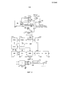
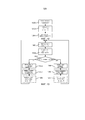
Фиг. 2 схематически иллюстрирует схему передатчика в соответствии с вариантом осуществления.FIG. 2 schematically illustrates a transmitter circuit in accordance with an embodiment.
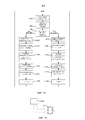
Фиг. 3 схематически иллюстрирует двухрежимный модулятор в соответствии с вариантом осуществления.FIG. 3 schematically illustrates a bimodal modulator in accordance with an embodiment.
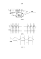
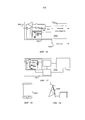
Фиг. 4 схематически иллюстрирует преобразователь на основе широтно-импульсной модуляции в соответствии с вариантом осуществления.FIG. 4 schematically illustrates a pulse width modulation converter in accordance with an embodiment.
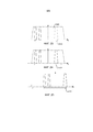
Фиг. 5 иллюстрирует работу преобразователя на основе широтно-импульсной модуляции в широкополосном режиме в соответствии с вариантом осуществления.FIG. 5 illustrates the operation of a pulse width modulated wideband converter in accordance with an embodiment.
Фиг. 6 иллюстрирует работу преобразователя на основе широтно-импульсной модуляции в узкополосном режиме в соответствии с вариантом осуществления.FIG. 6 illustrates the operation of a pulse-width modulated narrowband converter in accordance with an embodiment.
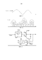
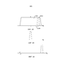
Фиг. 7 иллюстрирует напряжение питания для усилителя мощности при работе в режиме полярной модуляции.FIG. 7 illustrates the supply voltage for a power amplifier when operating in polar modulation mode.
Фиг. 8 иллюстрирует напряжение питания для усилителя мощности при работе в режиме отслеживания огибающей, а также соответствующий усиленный сигнал.FIG. 8 illustrates a supply voltage for a power amplifier when operating in envelope tracking mode, as well as a corresponding amplified signal.
Фиг. 9 схематически иллюстрирует структуру преобразователя напряжения с переключением режимов в соответствии с вариантом осуществления.FIG. 9 schematically illustrates the structure of a mode-switched voltage converter in accordance with an embodiment.
Фиг. 10 схематически иллюстрирует частоты среза для фильтра нижних частот, выполненного с возможностью фильтрования вывода из преобразователя напряжения с переключением режимов в соответствующих режимах работы.FIG. 10 schematically illustrates the cutoff frequencies for a low-pass filter configured to filter the output from a voltage converter with switching modes in respective operating modes.
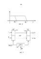
Фиг. 11 схематически иллюстрирует механизм коррекции задержки, выполненный с возможностью подбора задержки между амплитудной траекторией и фазовой траекторией в соответствии с вариантом осуществления.FIG. 11 schematically illustrates a delay correction mechanism configured to select a delay between an amplitude path and a phase path in accordance with an embodiment.
Фиг. 12 изображает блок-схему последовательности операций, иллюстрирующую способ в соответствии с вариантом осуществления.FIG. 12 is a flowchart illustrating a method in accordance with an embodiment.
Фиг. 13 изображает блок-схему последовательности операций, иллюстрирующую способ в соответствии с вариантом осуществления.FIG. 13 is a flowchart illustrating a method in accordance with an embodiment.
Фиг. 14 изображает блок-схему последовательности операций, иллюстрирующую способ в соответствии с вариантом осуществления.FIG. 14 is a flowchart illustrating a method in accordance with an embodiment.
Фиг. 15 схематически иллюстрирует энергонезависимую компьютерночитаемую среду хранения, содержащую компьютерную программу, которая может быть выполнена посредством процессора для реализации способов в соответствии с вариантами осуществления.FIG. 15 schematically illustrates a non-volatile computer readable storage medium comprising a computer program that can be executed by a processor to implement methods in accordance with embodiments.
Фиг. 16 схематически иллюстрирует радиосхему, включающую в себя схему передатчика в соответствии с вариантами осуществления.FIG. 16 schematically illustrates a radio circuit including a transmitter circuit in accordance with embodiments.
Фиг. 17 схематически иллюстрирует устройство связи, включающее в себя радиосхему в соответствии с вариантами осуществления.FIG. 17 schematically illustrates a communication device including a radio circuit in accordance with embodiments.
Фиг. 18 иллюстрирует устройство связи в соответствии с вариантом осуществления.FIG. 18 illustrates a communication device in accordance with an embodiment.
Фиг. 19 иллюстрирует узел связи в соответствии с вариантом осуществления.FIG. 19 illustrates a communication node in accordance with an embodiment.
Фиг. 20-22 иллюстрируют пример, в котором может быть использован нелинейный режим работы.FIG. 20-22 illustrate an example in which non-linear operation can be used.
Фиг. 23-25 иллюстрируют примеры, в которых должен быть использован линейный режим работы.FIG. 23-25 illustrate examples in which a linear mode of operation should be used.
ПОДРОБНОЕ ОПИСАНИЕDETAILED DESCRIPTION
Для понимания настоящего раскрытия читатель должен знать о том, что полярная модуляция предоставляет возможность использования нелинейного усилителя мощности (PA), который является энергоэффективным, но имеет проблемы с расширением полосы частот. Поэтому использование полярной модуляции не подходит для широкополосных систем, таких как широкополосная система 3GPP LTE, в которых могут быть использованы полосы частот в 20 МГц. Линейный усилитель PA с постоянным напряжением питания не имеет подобных проблем с расширением полосы частот, но является менее эффективным в отношении энергосбережения по сравнению с нелинейным усилителем PA. Линейный усилитель PA может быть сделан более энергоэффективным посредством использования отслеживания огибающей. Отслеживание огибающей требует использования линейного усилителя PA, который в сущности является менее энергоэффективным, чем нелинейный усилитель PA, но остается более эффективным по сравнению с усилителем PA без отслеживания огибающей, то есть усилителем РА с постоянным напряжением питания. Высокий энергетический коэффициент полезного действия подразумевает то, что на антенну подается большее количество мощности радиопередачи и/или то, что при заданной мощности питания усилитель мощности вырабатывает меньше тепла.To understand the present disclosure, the reader should be aware that polar modulation provides the possibility of using a non-linear power amplifier (PA), which is energy efficient but has problems with expanding the frequency band. Therefore, the use of polar modulation is not suitable for broadband systems, such as the 3GPP LTE broadband system, in which 20 MHz frequency bands can be used. A constant-voltage PA linear amplifier does not have similar bandwidth expansion problems, but is less energy efficient than a non-linear PA amplifier. The PA line amplifier can be made more energy efficient by using envelope tracking. Envelope tracking requires the use of a linear PA amplifier, which is essentially less energy efficient than a non-linear PA amplifier, but remains more efficient than a PA amplifier without tracking the envelope, that is, a constant current voltage amplifier PA. A high energy efficiency implies that more radio transmission power is supplied to the antenna and / or that at a given power supply, the power amplifier generates less heat.
Фиг. 1 иллюстрирует схему 100 передатчика, в соответствии с вариантом осуществления. Схема 100 передатчика включает в себя узел 106 немодулированной передачи, выполненный с возможностью выполнения любой обработки немодулированной передачи, и обеспечивает синфазные (I) и квадратурные фазовые (Q) составляющие сигнала, которые подлежат модуляции. Схема 100 передатчика также включает в себя усилитель 102 мощности, выполненный с возможностью вывода модулированного сигнала для передачи, например, напрямую на антенное устройство или на антенное устройство через выходную сеть, выполненную с возможностью обеспечения согласования полных сопротивлений. Схема 100 передатчика также включает в себя преобразователь 104 напряжения с переключением режимов, выполненный с возможностью подачи напряжения питания на усилитель 102 мощности. Предпочтительно, чтобы преобразователь 104 напряжения с переключением режимов являлся преобразователем постоянного тока в постоянный ток (DC/DC), который в свою очередь подключается к питанию любого устройства, в котором установлена схема 100 передатчика.FIG. 1 illustrates a
Для повышения эффективности схемы 100 передатчика усилитель 102 мощности выполняется с возможностью селективной работы в линейном или нелинейном режимах. Нелинейный режим позволяет повысить эффективность для усилителя мощности, который впоследствии может работать, например, согласно классу D или E. Линейный режим является менее эффективным, но обеспечивает необходимое свойство линейности для множества ситуаций с сигналом, например, чтобы избежать просачивания спектральных составляющих, которое выходит за пределы желаемых уровней, при этом усилитель мощности может работать, например, согласно классу A или AB. Чтобы извлечь выгоду из такой двухрежимной работы усилителя мощности, модуляция селективно выбирается между квадратурной модуляцией, которая требует линейного режима работы усилителя мощности, и полярной модуляцией, которая предоставляет усилителю мощности возможность работы в нелинейном режиме.To increase the efficiency of the
В данном варианте осуществления полярный модулятор 108 преобразовывает составляющие I и Q в фазовую составляющую, которая подается на усилитель мощности. Соответствующая амплитудная составляющая обеспечивается посредством амплитудного генератора 110, который получает амплитудную составляющую из составляющих I и Q, и передает амплитудную составляющую на коммутируемый генератор 104 напряжения, который в свою очередь управляет подачей напряжения на усилитель мощности, таким образом, чтобы амплитудная составляющая совместно с фазовой составляющей могли быть выведены посредством усилителя мощности в качестве полярного модулированного сигнала.In this embodiment, the
Подобным образом квадратурный модулятор 112 модулирует составляющие I и Q посредством смешивания с сигналом синфазного осциллятора и сигналом квадратурного фазового осциллятора, соответственно, и совокупность модулированных составляющих I и Q передаются на усилитель мощности. Теперь амплитудный генератор 110 используется для отслеживания огибающей и, на основе составляющих I и Q, передает сигнал огибающей на преобразователь 104 напряжения с переключением режимов таким образом, чтобы он подавал подходящее напряжение питания на усилитель мощности, причем усилитель мощности может работать в линейном режиме и усиливать совокупность модулированных составляющих I и Q. Сигнал огибающей отслеживает огибающую амплитудных сигналов составляющих I и Q и обеспечивает подходящий запас для линейного режима работы усилителя мощности.Similarly, the
Схемой 100 передатчика управляют для выбора наиболее эффективного из режимов работы на основе характеристик сигнала, который будет передаваться. Такое управление может быть обеспечено с узла 106 немодулированной передачи или же со специального контроллера (не изображен). Характеристика сигнала, который будет передаваться, оказывающая большое влияние на то, какой режим работы подходит для использования, является выделенной полосой частот. Решение, принятое в результате управления, может являться довольно простым, как, например, если полоса частот составляет 5 МГц или менее в случае использования системы 3GPP LTE, то выбирается полярная модуляция и нелинейный режим работы усилителя мощности, и если полоса частот превышает 5 МГц, то выбирается квадратурная модуляция и линейный режим работы усилителя мощности. Может быть обеспечено более сложное управление, в процессе которого используются характеристики модуляции составляющих I и Q с узла немодулированной передачи, то есть как используется пространство сигнала. Это может быть использовано совместно с информацией о выделенной полосе частот, например, для некоторых конфигураций составляющих I и Q, а также для немного более широких полос частот, используется полярная модуляция и нелинейный режим работы усилителя мощности, наряду с тем, что для некоторых других конфигураций составляющих I и Q, а также для менее узких полос частот, используется квадратурная модуляция и линейный режим работы усилителя мощности. Подобные решения для выбора режима работы могут быть основаны на одной или более из выходной мощности, амплитуды вектора ошибок и требовании по просачиванию спектральных составляющих для передачи, которая должна быть выполнена посредством передатчика. Поэтому несмотря на то что выделенная полоса частот играет главную роль в выборе, дальнейшая оптимизация может быть выполнена для полос частот среднего размера на основе использованного пространства сигнала, выходной мощности, амплитуды вектора ошибок и/или требовании по просачиванию спектральных составляющих.A
Выбор квадратурной модуляции/линейного режима работы или полярной модуляции/нелинейного режима работы может быть определен в соответствии с продемонстрированным выше таким образом, чтобы просачивание спектральных составляющих не выходило за пределы спецификации системы, в которой используется передатчик, например, за пределы того, что определено в документах 3GPP TS25.101, 3GPP TS 36.101 или подобных, для фактической системы.The choice of quadrature modulation / linear operating mode or polar modulation / non-linear operating mode can be determined in accordance with the above so that the leakage of spectral components does not go beyond the specification of the system in which the transmitter is used, for example, beyond what is defined in 3GPP TS25.101, 3GPP TS 36.101 or the like, for the actual system.
Информация о сигнале, который будет передаваться, и, следовательно, решение о выбранном режиме работы могут быть неоднократно получены заблаговременно, что упрощает реализацию. Например, в системе 3GPP LTE сообщение разрешения восходящей линии связи принимается на четыре подкадра раньше, что равняется четырем миллисекундам, вследствие чего передатчик уже является проинформированным о выделенной полосе частот и т.д., и может быть выполнена адаптация режима работы.Information about the signal that will be transmitted, and, therefore, a decision on the selected operating mode can be repeatedly received in advance, which simplifies the implementation. For example, in the 3GPP LTE system, an uplink grant message is received four subframes earlier, which equals four milliseconds, whereby the transmitter is already informed of the allocated frequency band, etc., and the operation mode can be adapted.
Разумеется, работа усилителя 102 мощности в линейном или нелинейном режиме может быть достигнута посредством селективного использования либо линейного усилителя мощности, либо нелинейного усилителя мощности, то есть при наличии отдельных усилителей мощности. Однако для исключения лишней схемы управление режимом работы усилителя мощности может включать в себя адаптивную настройку одного усилителя мощности для выбора режима работы, а именно, линейного или нелинейного режима. Выходная сеть также может быть адаптирована к режиму работы усилителя мощности для слежения за любыми нежелательными гармониками.Of course, the operation of the
Фиг. 2 схематически иллюстрирует схему 200 передатчика, в соответствии с вариантом осуществления. Процессор 212 немодулированной передачи (BBP) генерирует составляющие I и Q, подобно продемонстрированному со ссылкой на Фиг. 1. Составляющие I и Q передаются по двум трактам, а именно, по амплитудному тракту (вверх на Фиг. 2) и по фазовому тракту (вправо на Фиг. 2). Амплитудный тракт включает в себя генератор 214 огибающей/амплитуды (EAG), узел 216 предварительного искажения (PDIS), преобразователь 218 на основе широтно-импульсной модуляции (PWMC), преобразователь 204 напряжения с переключением режимов, фильтр 208 нижних частот (LPF), и двухрежимный усилитель 202 мощности (DMPA). Фазовый тракт включает в себя блок 220 коррекции задержки (DA), двухрежимный модулятор 210 (DMM) и DMPA 202, где эти два тракта совмещаются. Модулятору 210 DMM предоставляются квадратурные тактовые сигналы несущей радиочастоты (CQC) для разрешения модуляции. Сигнал CQC может содержать четыре сигнала с взаимным фазовым сдвигом на 90 градусов для разных смесителей, или два сигнала с взаимным фазовым сдвигом на 90 градусов для несимметричных смесителей.FIG. 2 schematically illustrates a
Контроллер 206 выполнен с возможностью управления элементами схемы 100 передатчика для работы в соответствии с первым режимом работы, то есть выполнение квадратурной модуляции и настройка линейного усилителя, и в соответствии со вторым режимом работы, то есть выполнение полярной модуляции и настройка нелинейного усилителя. Как правило, первый режим работы побуждает усилитель 202 DMPA к работе в линейном режиме, наряду с тем, что второй режим работы задает усилителю 202 DMPA нелинейный режим работы. Выход с преобразователя напряжения с переключением режимов в некоторых случаях подвергается обработке фильтром 208 нижних частот LPF перед подачей напряжения питания на усилитель 202 DMPA. Помимо всего прочего немодулированные составляющие I и Q, сгенерированные посредством процессора 212 BBP, в зависимости от режима работы, преобразовываются в сигнал огибающей или амплитудный сигнал посредством генератора 214 EAG, при этом сигнал огибающей или амплитудный сигнал может быть подвержен предварительному искажению при помощи узла 216 PDIS для сокращения нелинейности в процессе генерирования выходного сигнала на выходе усилителя 202 DMPA. Эта нелинейность может включать в себя любые дополнения от преобразователя 218 PWMC, преобразователя 204 напряжения с переключением режимов и усилителя 202 DMPA.The
Любая подборка задержки между трактом фазовой модуляции и амплитудным трактом может быть выравнена посредством блока 220 DA под управлением контроллера 206. Фильтр 208 LPF может иметь два режима, один для использования в широкополосных системах, и второй для использования в узкополосных системах, которые выбираются либо посредством электрического средства, либо посредством механического средства. Функция фильтра 208 LPF заключается в сокращении ряби на выходе преобразователя напряжения с переключением режимов, улучшения соотношения просачивания соседнего канала в отношении помех полосы частот для удовлетворения спектральных масок, определенных стандартами радиосвязи, а также в подавлении просачиваний спектральных составляющих передатчика в полосу приемника при использовании в терминале радиосвязи схемы 200 передатчика, что подразумевает смягчение требований для затухания в полосе приемника в фильтрах поверхностных акустических волн или дуплексерах.Any delay selection between the phase modulation path and the amplitude path can be aligned by the
После усилителя 202 DMPA усиленный сигнал может быть передан на выходную сеть 222 ON, которая включает в себя согласование полного сопротивления, которое минимизирует отражения и подает большую часть энергии сигнала на антенну, и, в случае использования сбалансированной топологии усилителя мощности, дифференциал для несимметричного преобразования. Выход 222 ON также может гасить нежелательные частотные составляющие, созданные вследствие нелинейности усилителя мощности. Сеть 222 ON также может находиться под управлением контроллера 206 и адаптироваться на основе режима работы усилителя 202 мощности.After the
Первый режим работы, то есть линейный режим работы, нацелен на применение в системах, использующих широкую полосу, то есть имеющих выделенную широкую полосу частот и/или имеющих схему модуляции, использующую пространство сигнала для больших символов, например, пользовательский сценарий в системе 3GPP LTE, использующей полосу частот в 20 МГц. Таким образом в линейном режиме требование к рабочей частоте или полосе частот намного выше для всех блоков, вследствие чего снижается энергетический коэффициент полезного действия. Однако, поскольку обычно интервал занятости является коротким, и вероятность этого является относительно низкой по сравнению с работой в узкополосных системах, можно перенести эти энергетические затраты.The first mode of operation, that is, the linear mode of operation, is aimed at applications in systems using a wide band, that is, having a dedicated wide band of frequencies and / or having a modulation scheme using signal space for large characters, for example, a user script in the 3GPP LTE system, using a frequency band of 20 MHz. Thus, in linear mode, the requirement for the operating frequency or frequency band is much higher for all blocks, as a result of which the energy efficiency is reduced. However, since the employment interval is usually short, and the probability of this is relatively low compared to working in narrow-band systems, these energy costs can be transferred.
Второй режим, то есть нелинейный режим, разработан с возможностью применения в большинстве узкополосных систем, во множестве стандартов, например GSM, EDGE и т.д., и даже в узкополосном пользовательском сценарии в системе 3GPP LTE с выделенной полосой частот вплоть до 5 МГц.The second mode, that is, the nonlinear mode, is designed to be used in most narrowband systems, in many standards, for example GSM, EDGE, etc., and even in a narrowband user scenario in a 3GPP LTE system with a dedicated frequency band up to 5 MHz.
Далее, со ссылкой на Фиг. 3-11, будут проиллюстрированы функции, операции и возможные варианты в отношении элементов схемы 200 передатчика.Next, with reference to FIG. 3-11, functions, operations, and possible variations will be illustrated with respect to elements of a
Фиг. 3 схематически иллюстрирует двухрежимный модулятор 300 DMM, в соответствии с вариантом осуществления. В тракте фазовой модуляции, изображенном на Фиг. 2, блок 220 DA используется для подборки задержки между амплитудным трактом и фазовым трактом. В зависимости от задержки в фазовом тракте и амплитудном тракте в отношении практического варианта реализации, блок 220 DA может быть перемещен в любую позицию в фазовом или амплитудном тракте, а также может быть реализован либо цифровым, либо аналоговым способом. Для иллюстрации модулятора 300 DMM на Фиг. 3, предполагается, что блок DA обеспечивается в фазовом тракте и обеспечивает модулятору 300 DMM задержанные составляющие Id и Qd. Двухрежимный модулятор преобразовывает входные сигналы Id и Qd в сигналы U и V посредством матрицы А в узле 304 преобразования, затем сигналы U и V модулируются посредством квадратурных тактовых сигналов несущей радиочастоты, вследствие чего создается радиосигнал. Матрица A может быть реализована в таблице преобразования или в ячейках ROM или RAM. В первом режиме, который используется для систем с отслеживанием огибающей, узел 304 преобразования попросту пропускается, имеяFIG. 3 schematically illustrates a dual-
U=IdU = id
V=QdV = qd
Во втором режиме узел преобразования выполняет следующее нелинейное преобразование:In the second mode, the transformation node performs the following non-linear transformation:

Следовательно, сигналы U и V являются квадратурными сигналами с нормализованной амплитудой. После квадратурной модуляции выход может быть выражен в следующем виде:Therefore, the signals U and V are quadrature signals with a normalized amplitude. After quadrature modulation, the output can be expressed as follows:

Подразумевается, что в первом режиме модулятор выполняет нормальную линейную квадратурную модуляцию, наряду с тем, что во втором режиме работы, модулятор объединяет нормальную линейную квадратурную модуляцию с функцией ограничителя.It is understood that in the first mode, the modulator performs normal linear quadrature modulation, while in the second mode of operation, the modulator combines normal linear quadrature modulation with a limiter function.
Функция ограничителя также может быть реализована аналоговыми способами, в связи с этим на Фиг. 3 изображена примерная схема, в которой используется аналоговый ограничитель 302 и мультиплексор 306.The limiter function can also be implemented in analogue ways, in connection with this in FIG. 3 shows an exemplary circuit in which an
Фиг. 4 схематически иллюстрирует преобразователь 400 на основе широтно-импульсной модуляции, в соответствии с вариантом осуществления. Генератор 214 огибающей/амплитуды (EAG), изображенный на Фиг. 2, создает цифровой амплитудный сигнал огибающей или полярной модуляции, в соответствии с квадратурными цифровыми входными составляющими I и Q. Для выполнения полярной модуляции используется взаимное однозначное соответствиеFIG. 4 schematically illustrates a pulse
![]()
![]()
Наряду с тем, что для сигналов огибающей генерирование может не являться уникальным, например, сигнал огибающей может быть создан посредствомAlong with the fact that for the envelope signals the generation may not be unique, for example, the envelope signal can be created by
![]()
![]()
Где h() является коэффициентами цифрового фильтра, а G0() создает интервал напряжения между максимальной амплитудой и напряжением питания для гарантии того, что линейный усилитель мощности всегда работает в линейной области. Другой пример может иметь следующий вид:Where h () is the coefficients of the digital filter, and G 0 () creates a voltage interval between the maximum amplitude and the supply voltage to ensure that the linear power amplifier always operates in the linear region. Another example may look like this:
![]()
![]()
Сигнал огибающей или амплитудные сигналы могут быть подвержены дискретизации с уменьшением шага и сглаживанию цифровыми способами.Envelope or amplitude signals may be subject to sampling with decreasing pitch and digital smoothing.
Выход РО усилителя мощности, к сожалению, является нелинейной функцией сигнала огибающей или амплитудного сигнала, PO=f(env) или PO=g(amp). В узле PDIS сигнал огибающей или амплитудный сигнал подвергается нелинейному преобразованию в сигнал Penv или Pamp посредством функции предварительного искажения P и QThe output P O of the power amplifier, unfortunately, is a non-linear function of the envelope signal or the amplitude signal, P O = f (env) or P O = g (amp). At the PDIS node, the envelope signal or the amplitude signal is non-linearly converted to a Penv or Pamp signal using the pre-distortion function P and Q

Где P или Q является обратной функцией f(.) или G(.), которая сокращает амплитудное искажение в амплитудном тракте. Where P or Q is the inverse function of f (.) Or G (.), Which reduces the amplitude distortion in the amplitude path.
Посредством преобразователя 400 PWMC цифровой сигнал Penv преобразовывается в импульсную последовательность на основе широтно-импульсной модуляции (PWM), в которой ширина импульса является функцией входного напряжения, а частота импульсов является СS. Существует множество различных способов создания последовательности PWM. Например, последовательность на основе широтно-импульсной модуляции может быть создана посредством извлечения пилообразного входного сигнала (напряжения), обеспечиваемого посредством генератора 404 пилообразного напряжения с частотой повторения СS, как изображено на Фиг.4, при этом преобразователь PWMC может иметь два режима, иллюстрированные на Фиг. 5 и 6, для широкополосного сигнала и узкополосного сигнала, соответственно, управляемые посредством сигнала CTRL, который изменяет коэффициент деления делителя 402 частоты.By means of the
Частота переключения импульсной последовательности PWM определяет эффективность преобразования преобразователя напряжения с переключением режимов, поскольку регулировочный транзистор в преобразователе напряжения с переключением режимов работает на этой частоте, а также заряжает и разряжает емкость в нагрузке и фильтре LPF, что приводит к динамическому энергопотреблению. Динамическая мощность снижает эффективность преобразования в преобразователе напряжения с переключением режимов. В соответствии с конкретным пользовательским сценарием, контроллер задает коэффициент деления, соответствующий полосе частот, который в свою очередь оптимизирует эффективность преобразования преобразователя напряжения с переключением режимов.The switching frequency of the pulse sequence PWM determines the conversion efficiency of the voltage converter with mode switching, since the regulating transistor in the voltage converter with mode switching operates at this frequency, and also charges and discharges the capacitance in the load and LPF filter, which leads to dynamic power consumption. Dynamic power reduces conversion efficiency in a voltage converter with mode switching. In accordance with a specific user scenario, the controller sets the division coefficient corresponding to the frequency band, which in turn optimizes the conversion efficiency of the voltage converter with switching modes.
Преобразователь DC/DC напряжения с переключением режимов также может работать в двух режимах. Один режим работы используется для узкополосных систем, в которых реализуется полярная модуляция, иллюстрированная на Фиг. 7, а другой режим работы используется для линейного режима, то есть широкополосного режима, в котором выполняется отслеживание огибающей, изображенное на Фиг. 8.The switching DC / DC voltage converter can also work in two modes. One mode of operation is used for narrowband systems in which polar modulation is implemented, as illustrated in FIG. 7, and another mode of operation is used for the linear mode, that is, the broadband mode in which the envelope tracking shown in FIG. 8.
В узкополосных системах преобразователь напряжения с переключением режимов имеет структуру, подобную структуре обычного преобразователя 904 DC/DC, а скорость нарастания напряжения на выходе преобразователя 904 является достаточной для сопровождения изменения сигнала Penv, как иллюстрировано на Фиг. 7. В широкополосных системах в случае расширения полосы частот может быть автоматически включен дополнительный быстродействующий переключатель 902 и быстродействующий компаратор 906, как иллюстрировано на Фиг. 9. Выход компаратора 906 подводится к логической схеме 908, которая в свою очередь управляет переключателями переключающего средства 902.In narrowband systems, the mode-switched voltage converter has a structure similar to that of a conventional DC /
В некоторых случаях фильтр 208 LPF, изображенный на Фиг. 2, может быть разработан так, чтобы он имел различные частоты среза, как иллюстрировано на Фиг. 10, при этом фильтр LPF может включать в себя пассивные элементы LC, MEMS или другие полупроводниковые переключатели с малыми вносимыми потерями.In some cases, the
Усилитель DMPA имеет два режима работы, то есть линейный режим, предназначенный для работы с отслеживанием огибающей, и нелинейный режим, предназначенный для работы с полярной модуляцией, соответствующей требованию полосы частот и т.д., для различных систем. Режим работы может быть изменен посредством задания рабочей точки усилителя мощности. Например, в линейном режиме работы усилитель мощности может работать согласно классу A или AB. Для повышения энергетического коэффициента полезного действия усилитель мощности также может работать в нелинейном режиме, согласно классу D или E, по существу, без существенного изменения топологии усилителя, предполагая, что выходная сеть может убирать любые нежелательные гармонические составляющие. Разумеется, также имеется возможность параллельного использования линейного усилителя мощности и нелинейного усилителя мощности, причем каждый из них имеет разрешенное управление, но управление во время работы разрешается только одному из них.The DMPA amplifier has two operating modes, that is, a linear mode designed to work with envelope tracking, and a non-linear mode designed to work with polar modulation corresponding to the requirement of a frequency band, etc., for various systems. The operating mode can be changed by setting the operating point of the power amplifier. For example, in linear operation, a power amplifier can operate according to class A or AB. To increase the energy efficiency, the power amplifier can also operate in a nonlinear mode, according to class D or E, essentially without a significant change in the amplifier topology, assuming that the output network can remove any unwanted harmonic components. Of course, it is also possible to use a linear power amplifier and a non-linear power amplifier in parallel, each of which has an authorized control, but only one of them is allowed to operate during operation.
Фиг. 11 иллюстрирует блок 1100 DA, в соответствии с вариантом осуществления. Составляющие I и Q подаются на регистровую матрицу 1102 под управлением тактового сигнала и выводятся с выходных регистров 1104 под управлением настроенного тактового сигнала, причем настроенный тактовый сигнал обеспечивается посредством настраиваемого фазорегулятора 1106, управление которым предпочтительно осуществляется посредством контроллера 206, изображенного на Фиг. 2. В зависимости от задержки в фазовом тракте и амплитудном тракте в практическом варианте реализации, блок коррекции задержки может быть перемещен в любую позицию фазового или амплитудного тракта, и реализован либо цифровым, либо аналоговым способом.FIG. 11 illustrates a
Фиг. 12 изображает блок-схему последовательности операций, иллюстрирующую способ, в соответствии с вариантом осуществления. На этапе 1200 передатчик работает согласно технологии радиодоступа RAT, которая, например, может являться GSM, EDGE, WCDMA или LTE. На этапе 1202 определяется выделенная полоса частот для передачи, которая должна быть выполнена. Для некоторых технологий RAT, таких как GSM, определение может быть выполнено довольно просто, в связи с тем, что технология RAT поддерживает только полосы частот ниже порога, где может быть использован нелинейный режим работы. Для других технологий RAT, таких как LTE, выделенная полоса частот может подразумевать использование либо нелинейного режима работы, который является предпочтительным вследствие высокой эффективности, либо линейного режима работы. Следовательно, в соответствии с вышеупомянутым, на этапе 1204 определяется режим работы для усилителя мощности и т.д., чтобы передатчик мог быть соответственно настроен и выполнял передачу. Процедура постоянно повторяется, при этом следующая передача может быть выполнена согласно такой же или другой технологии RAT с использованием другой выделенной полосы частот, кроме того, для этой передачи выбирается подходящий режим работы.FIG. 12 is a flowchart illustrating a method in accordance with an embodiment. At
Фиг. 13 изображает блок-схему последовательности операций, иллюстрирующую способ, в соответствии с вариантом осуществления. На этапе 1300 передатчик работает согласно технологии RAT, которая, например, может являться GSM, EDGE, WCDMA или LTE. На этапе 1302 определяется выделенная полоса частот для передачи, которая должна быть выполнена. Для некоторых технологий RAT, таких как GSM, определение может быть выполнено довольно просто, в связи с тем, что технология RAT поддерживает только полосы частот ниже порога, где может быть использован нелинейный режим работы. Для других технологий RAT, таких как LTE, выделенная полоса частот может подразумевать использование либо нелинейного режима работы, который является предпочтительным вследствие высокой эффективности, либо линейного режима работы. В случае использования LTE, выделенная полоса частот будет известна на четыре подкадра ранее из сообщения разрешения восходящей линии связи. На этапе 1304 выделенная полоса частот сравнивается с порогом.FIG. 13 is a flowchart illustrating a method in accordance with an embodiment. At
Если выделенная полоса частот превышает порог, который, например, может быть равен 5 МГц, то на этапе 1305 выполняется отслеживание огибающей, а на этапе 1307 для усилителя мощности выбирается линейный режим. В некоторых случаях на этапе 1309 для фильтра нижних частот, расположенного на выходе преобразователя напряжения с переключением режимов, может быть выбрана более высокая частота среза (по сравнению с той, которая будет использоваться для полярной модуляции).If the allocated frequency band exceeds a threshold, which, for example, can be equal to 5 MHz, then the envelope is tracked at
Если выделенная полоса частот не превышает порог, то на этапе 1306 выполняется полярная модуляция, а на этапе 1308 для усилителя мощности выбирается нелинейный режим. В некоторых случаях на этапе 1310 для фильтра нижних частот, расположенного на выходе преобразователя напряжения с переключением режимов, может быть выбрана меньшая частота среза (по сравнению с той, которая будет использоваться для отслеживания огибающей).If the allocated frequency band does not exceed the threshold, then at
Следовательно, режим работы для усилителя мощности и т.д., в соответствии с вышеупомянутым, настраивается таким образом, чтобы передатчик мог выполнять передачу наиболее эффективно. Процедура постоянно повторяется, при этом следующая передача может быть выполнена согласно такой же или другой технологии RAT с использованием другой выделенной полосы частот, кроме того, для этой передачи выбирается подходящий режим работы.Therefore, the operation mode for the power amplifier, etc., in accordance with the above, is adjusted so that the transmitter can transmit most efficiently. The procedure is constantly repeated, while the next transmission can be performed according to the same or different RAT technology using a different allocated frequency band, in addition, an appropriate operating mode is selected for this transmission.
Фиг. 14 изображает блок-схему последовательности операций, иллюстрирующую способ, в соответствии с вариантом осуществления. На этапе 1400 передатчик работает согласно технологии RAT, которая, например, может являться GSM, EDGE, WCDMA или LTE. На этапе 1402 определяются характеристики передачи, такие как модуляция, выходная мощность, амплитуда вектора ошибок и/или требования по просачиванию спектральных составляющих, а также выделенная полоса частот для передачи, которая должна быть выполнена. На этапе 1404 выполняется преобразование характеристик передачи в подходящий режим работы. Преобразование может включать в себя обращение к таблице преобразования.FIG. 14 is a flowchart illustrating a method in accordance with an embodiment. At
После преобразования характеристик передачи в первый режим работы, на этапе 1405 усилитель мощности переводится в линейный режим работы, на этапе 1407 составляющие I и Q, обеспечиваемые от немодулированной передачи, преобразовываются в сигнал огибающей, а на этапе 1409 преобразователем напряжения с переключением режимов управляют в соответствии с сигналом огибающей. Кроме того, на этапе 1411 может быть выполнена предварительная компенсация составляющих I и Q и/или на этапе 1413, как было упомянуто выше, может быть сделан выбор более высокой частоты среза фильтра LPF. На этапе 1415 выполняется передача, в соответствии с настройками и использованием квадратурной модуляции с отслеживанием огибающей, как было упомянуто выше, после чего осуществляется возврат процедуры для выполнения следующей передачи.After converting the transmission characteristics to the first mode of operation, at
После преобразования характеристик передачи во второй режим работы, на этапе 1406 усилитель мощности переводится в нелинейный режим работы, на этапе 1408 составляющие I и Q преобразовываются в амплитудный сигнал, на этапе 1410 преобразователем напряжения с переключением режимов управляют в соответствии с амплитудным сигналом, а на этапе 1412 составляющие I и Q преобразовываются в фазовый сигнал, например, посредством ограничения либо цифровым способом, либо посредством аналогового ограничителя. Кроме того, на этапе 1414 может быть уменьшена частота среза фильтра LPF. На этапе 1416 передача выполняется в соответствии с настройками и использованием полярной модуляции, как было упомянуто выше, после чего осуществляется возврат процедуры для выполнения следующей передачи.After converting the transmission characteristics to the second mode of operation, at
Выше, со ссылкой на Фиг. 12-14, были продемонстрированы способы в качестве нескольких различных примеров. Однако следует подразумевать, что некоторые действия в одном примере могут быть заменены другим соответствующим действием из другого примера, например, этап сравнения с порогом полосы частот может быть заменен этапом преобразования характеристик передачи или наоборот. Кроме того, несмотря на то, что этапы были представлены в последовательном порядке, как правило, это не отражает реальный рабочий процесс. Разъясненные настройки обычно выполняются параллельно или, по меньшей мере, выполняются по мере доступности необходимых входных данных для настройки. В качестве нескольких примеров, элементы амплитудного тракта настраиваются одновременно с настройками элементов фазового тракта, а управление преобразователем напряжения с переключением режимов выполняется в течение всей передачи, причем определение характеристик передачи для следующей передачи, как правило, начинается перед выполнением предшествующей передачи и т.д.Above, with reference to FIG. 12-14, methods were demonstrated as several different examples. However, it should be understood that some actions in one example can be replaced by another corresponding action from another example, for example, the step of comparing with a frequency band threshold can be replaced by the step of converting transmission characteristics or vice versa. In addition, although the steps were presented in sequential order, as a rule, this does not reflect the actual work process. The clarified settings are usually performed in parallel or, at least, performed as the necessary input for the settings is available. As a few examples, the elements of the amplitude path are adjusted simultaneously with the settings of the elements of the phase path, and the voltage converter is controlled with the switching of modes during the entire transmission, and the determination of the transmission characteristics for the next transmission usually starts before the previous transmission, etc.
Способы, в соответствии с настоящим изобретением, делаются подходящими для варианта реализации при помощи средств обработки, таких как компьютеры и/или процессоры, специально для примерного случая, в котором подходящий режим работы должен быть определен на основе сложной информации и/или сигналов, обеспечиваемых для модуляции в различных режимах работы, которые должны быть определены соответствующим образом. Исходя из вышесказанного, обеспечиваются компьютерные программы, содержащие команды, побуждающие средства обработки, процессор или компьютер к выполнению этапов любого из способов, в соответствии с любым из вариантов осуществления, описанных со ссылкой на любую из Фиг. 12-14. Предпочтительно, чтобы компьютерные программы содержали программный код, который сохраняется на компьютерночитаемой среде 1500, как иллюстрировано на Фиг. 15, который может быть загружен и выполнен посредством средств обработки, процессора или компьютера 1502, чтобы побудить его к выполнению способов, соответственно, в соответствии с вариантами осуществления настоящего изобретения, предпочтительно в качестве любого из вариантов осуществления, описанных со ссылкой на любую из Фиг. 12-14. Компьютер 1502 и компьютерный программный продукт 1500 могут быть выполнены с возможностью последовательного выполнения программного кода, в процессе которого действия любого из способов выполняются пошаговым способом. Предпочтительно, чтобы средства обработки, процессор или компьютер 1502 обычно назывались встроенной системой. Поэтому изображенные на Фиг. 15 компьютерночитаемая среда 1500 и компьютер 1502 должны быть восприняты исключительно в иллюстративных целях для обеспечения понимания принципа, а не в качестве какой-либо четкой иллюстрации элементов.The methods in accordance with the present invention are made suitable for an embodiment using processing means such as computers and / or processors, especially for an example case in which a suitable operating mode must be determined based on complex information and / or signals provided for modulations in various modes of operation, which must be determined accordingly. Based on the foregoing, computer programs are provided comprising instructions that prompt processing means, a processor, or a computer to perform steps of any of the methods, in accordance with any of the embodiments described with reference to any of FIGS. 12-14. Preferably, the computer programs comprise program code that is stored on a computer-
Фиг. 16 схематически иллюстрирует радиосхему 1600, в соответствии с вариантом осуществления. Радиосхема 1600 включает в себя схему 1602 передатчика, в соответствии с любым из представленных вариантов осуществления. Схема передатчика обеспечивает свой выходной сигнал на одну или более антенн 1608 зачастую через линию передачи и/или выходную сеть. Радиосхема 1600 также может включать в себя другую радиосхему 1604, которая, например, может включать в себя приемник, устройство обработки сигналов, интерфейсную схему и т.д. Также радиосхема 1600 может включать в себя несколько схем 1602 передатчика, например, одну, выполненную с возможностью работы с сотовой сетью связи, и другую, выполненную с возможностью работы с беспроводной точкой доступа. Радиосхема 1600 также может включать в себя контроллер 1606, который, например, может обеспечить полученные данные о предстоящей передаче на схему 1602 передатчика.FIG. 16 schematically illustrates a
Фиг. 17 схематически иллюстрирует устройство 1700 связи, в соответствии с вариантом осуществления. Устройство связи включает в себя радиосхему 1702, в соответствии с любым из вышеупомянутых вариантов осуществления. Устройство 1700 связи также включает в себя дополнительную схему и элементы 1704, такие как устройства ввода и вывода, интерфейсы, источники питания и т.д. Радиосхема 1702 подключается к дополнительной схеме 1704 для обеспечения или приема сигналов, которые принимаются или предназначаются для передачи. Кроме того, дополнительная схема и элементы 1704 могут передавать управляющую информацию на контроллер радиосхемы 1702.FIG. 17 schematically illustrates a
Фиг. 18 схематически иллюстрирует пример устройства 1800 мобильной связи, в соответствии с вариантом осуществления. Устройство мобильной связи может обеспечивать возможность осуществления связи в сотовой системе радиосвязи и включать в себя вышеупомянутые элементы.FIG. 18 schematically illustrates an example of a
Фиг. 19 схематически иллюстрирует пример узла 1900 связи, в соответствии с вариантом осуществления, предназначенного для управления сотой в сотовой системе связи.FIG. 19 schematically illustrates an example of a
Узел 1900 связи может быть выполнен с возможностью управления сотой в сотовой системе связи и включать в себя вышеупомянутые элементы.The
Фиг. 20-22 иллюстрируют пример пользовательского сценария, в котором может быть использована полярная модуляция. На Фиг. 20 изображен спектр 2000 LTE для целой обсуждаемой полосы частот. Спектр может совместно использоваться множеством пользователей. На Фиг. 20 также изображается пользовательская полоса 2002 частот, то есть выделенная полоса частот.FIG. 20-22 illustrate an example of a user scenario in which polar modulation can be used. In FIG. 20 depicts a 2000 LTE spectrum for the entire frequency band discussed. The spectrum can be shared by many users. In FIG. 20 also depicts a
Фиг. 21 изображает спектр амплитуды блоков ресурсов, используемых пользователем. Фиг. 22 изображает фазомодулированные тактовые радиосигналы. При использовании такого пользовательского сценария на восходящей линии связи LTE с полным спектром 2000, когда пользователь планирует использование нескольких совокупных блоков ресурсов с частотным сдвигом 2004 от центральной частоты спектра 2000 и выделенной полосы 2002 частот, амплитуда немодулированного сигнала будет иметь относительно узкую полосу частот по сравнению с полосой частот спектра 2000 LTE. Поэтому передатчик может работать во втором режиме работы и использовать полярную модуляцию. Тракт фазовой модуляции генерирует фазомодулированные тактовые радиосигналы, частота которых приблизительно равна частоте несущей с добавленной частотой 2004 смещения, как иллюстрировано на Фиг. 22.FIG. 21 shows an amplitude spectrum of resource blocks used by a user. FIG. 22 shows phase-modulated clock radio signals. When using such a user scenario on an uplink LTE with a full spectrum of 2000, when the user plans to use several aggregate resource blocks with a frequency shift of 2004 from the center frequency of the spectrum of 2000 and the allocated
Фиг. 23-25 иллюстрируют пример пользовательского сценария, в котором должно быть использовано отслеживание огибающей. На Фиг. 23 изображен спектр 2300 LTE для целой обсуждаемой полосы частот. Спектр может совместно использоваться множеством пользователей. На Фиг. 23 также изображается пользовательская полоса 2302 частот, то есть выделенная полоса частот, охватывающая выделенные блоки ресурсов, распределенные в различных частотных позициях. При использовании такого пользовательского сценария на восходящей линии связи LTE с полным спектром 2300, когда пользователь планирует использование блоков ресурсов, которые распределены по спектру 2300, и поэтому сигналы имеют выделенную полосу 2302 частот, которая имеет ширину, практически равную ширине полосы частот спектра 2300 LTE. В первом варианте выбора передатчик может работать в первом режиме работы, предпочтительно на основе отслеживания огибающей, использующей несущую частоту центральной частоты спектра LTE с полосой 2402 частот, изображенной на Фиг. 24. Во втором варианте выбора модулятор может генерировать квадратурно модулированные тактовые радиосигналы, частота которых приблизительно равна центральной частоте спектра LTE с добавленной частотой смещения, как иллюстрировано на Фиг. 25, с полосой 2502 частот, которая является эквивалентной полосе 2302 частот.FIG. 23-25 illustrate an example of a user scenario in which envelope tracking should be used. In FIG. 23 depicts the 2300 LTE spectrum for the entire frequency band discussed. The spectrum can be shared by many users. In FIG. 23 also depicts a
Изобретение было описано выше преимущественно со ссылкой на несколько вариантов осуществления. Однако специалистам в данной области техники должно быть понятно, что в рамках изобретения также возможно использовать и другие варианты осуществления, отличные от раскрытых выше, как определяется посредством приложенной формулы изобретения.The invention has been described above mainly with reference to several embodiments. However, it will be understood by those skilled in the art that it is also possible within the scope of the invention to use other embodiments other than those described above as defined by the appended claims.
Claims (33)


Applications Claiming Priority (5)
| Application Number | Priority Date | Filing Date | Title |
|---|---|---|---|
| EP20110194588 EP2608415B1 (en) | 2011-12-20 | 2011-12-20 | Transmitter, transceiver, communication device, method and computer program |
| EP11194588.7 | 2011-12-20 | ||
| US201261582541P | 2012-01-03 | 2012-01-03 | |
| US61/582,541 | 2012-01-03 | ||
| PCT/SE2012/051345 WO2013095263A2 (en) | 2011-12-20 | 2012-12-05 | Selective power amplifier |
Related Child Applications (1)
| Application Number | Title | Priority Date | Filing Date |
|---|---|---|---|
| RU2017108759A Division RU2730281C2 (en) | 2011-12-20 | 2012-12-05 | Selective power amplifier |
Publications (2)
| Publication Number | Publication Date |
|---|---|
| RU2014129827A RU2014129827A (en) | 2016-02-10 |
| RU2615331C2 true RU2615331C2 (en) | 2017-04-04 |
Family
ID=45372252
Family Applications (2)
| Application Number | Title | Priority Date | Filing Date |
|---|---|---|---|
| RU2014129827A RU2615331C2 (en) | 2011-12-20 | 2012-12-05 | Selective power amplifier |
| RU2017108759A RU2730281C2 (en) | 2011-12-20 | 2012-12-05 | Selective power amplifier |
Family Applications After (1)
| Application Number | Title | Priority Date | Filing Date |
|---|---|---|---|
| RU2017108759A RU2730281C2 (en) | 2011-12-20 | 2012-12-05 | Selective power amplifier |
Country Status (11)
| Country | Link |
|---|---|
| US (4) | US9392560B2 (en) |
| EP (2) | EP2800278B1 (en) |
| CN (2) | CN105720926B (en) |
| DK (1) | DK2608415T3 (en) |
| ES (1) | ES2578810T3 (en) |
| HU (1) | HUE029292T2 (en) |
| PL (1) | PL2800278T3 (en) |
| PT (1) | PT2608415E (en) |
| RU (2) | RU2615331C2 (en) |
| WO (1) | WO2013095263A2 (en) |
| ZA (2) | ZA201403904B (en) |
Cited By (1)
| Publication number | Priority date | Publication date | Assignee | Title |
|---|---|---|---|---|
| RU2752228C1 (en) * | 2020-12-18 | 2021-07-23 | Сергей Сергеевич Печников | Method and device for converting structure of spectral-efficient radio signals for amplification in nonlinear power amplifiers |
Families Citing this family (18)
| Publication number | Priority date | Publication date | Assignee | Title |
|---|---|---|---|---|
| US10853292B2 (en) * | 2013-08-29 | 2020-12-01 | Hewlett-Packard Development Company, L.P. | Operation of a switch in linear mode |
| US20150280657A1 (en) * | 2014-03-28 | 2015-10-01 | Qualcomm Incorporated | Adaptive digital pre-distortion |
| US9876515B2 (en) * | 2014-06-05 | 2018-01-23 | Nokia Technologies Oy | Adaptive transmitter efficiency optimization |
| US9722771B2 (en) * | 2015-09-30 | 2017-08-01 | Skyworks Solutions, Inc. | Parallel use of serial controls in improved wireless devices and power amplifier modules |
| JP7458147B2 (en) | 2016-01-13 | 2024-03-29 | ストラ エンソ オーユーイー | Method for producing 2,5-furandicarboxylic acid and its intermediates and derivatives |
| KR102468952B1 (en) | 2016-03-07 | 2022-11-22 | 삼성전자주식회사 | Electronic apparatus and method for transceiving signals |
| US10827438B2 (en) | 2016-03-31 | 2020-11-03 | Telefonaktiebolaget L M Ericsson (Publ) | Systems and methods for determining an over power subscription adjustment for a radio equipment |
| US10186910B2 (en) | 2016-07-15 | 2019-01-22 | The United States Of America, As Represented By The Secretary Of The Army | Signal comparison and direction |
| CN114826502B (en) | 2017-04-28 | 2024-07-19 | 松下电器(美国)知识产权公司 | Communication device and communication method |
| CN110997647A (en) | 2017-07-12 | 2020-04-10 | 斯道拉恩索公司 | Purified 2, 5-furandicarboxylic acid pathway products |
| US10333763B1 (en) * | 2018-06-18 | 2019-06-25 | Futurewei Technologies, Inc. | System and method for hybrid transmitter |
| US11055361B2 (en) * | 2019-01-07 | 2021-07-06 | Microsoft Technology Licensing, Llc | Extensible framework for executable annotations in electronic content |
| CN110034779B (en) * | 2019-04-28 | 2021-01-05 | 北京智芯微电子科技有限公司 | eMTC communication module |
| CN110580384B (en) * | 2019-08-19 | 2021-03-30 | 华南理工大学 | Nonlinear modeling method for simultaneously solving multi-scale state variables of switching converter |
| CN111726140B (en) * | 2020-06-19 | 2022-06-10 | 维沃移动通信有限公司 | Power amplifier control method and device, WIFI radio frequency circuit and electronic equipment |
| US11609247B2 (en) * | 2020-10-21 | 2023-03-21 | Qualcomm Incorporated | System and method for active S11 detection in phased array transceivers |
| CN112469112B (en) * | 2020-11-25 | 2023-03-21 | Oppo(重庆)智能科技有限公司 | Frequency control method, device, radio frequency system and communication equipment |
| CN113422613B (en) * | 2021-05-11 | 2022-08-23 | 翱捷科技股份有限公司 | High-efficiency multimode radio frequency transmitter |
Citations (5)
| Publication number | Priority date | Publication date | Assignee | Title |
|---|---|---|---|---|
| RU2119714C1 (en) * | 1993-10-28 | 1998-09-27 | Моторола, Инк. | Method and device for reducing maximum envelope power of linear power amplifier |
| EP1492229A1 (en) * | 2003-06-24 | 2004-12-29 | Northrop Grumman Corporation | Polar and linear amplifier system |
| RU2305896C2 (en) * | 2002-04-05 | 2007-09-10 | Телефонактиеболагет Лм Эрикссон (Пабл) | Transmitter with multiple modulation |
| US20100056068A1 (en) * | 2008-09-03 | 2010-03-04 | Matsushita Electric Industrial Co., Ltd. | Multi-mode transmitter having adaptive operating mode control |
| WO2011050033A1 (en) * | 2009-10-20 | 2011-04-28 | Qualcomm Incorporated | Apparatus and methods for qam modulation using dual polar modulation |
Family Cites Families (32)
| Publication number | Priority date | Publication date | Assignee | Title |
|---|---|---|---|---|
| US5060294A (en) | 1990-07-05 | 1991-10-22 | Motorola, Inc. | Dual mode power amplifier for radiotelephone |
| US5251331A (en) * | 1992-03-13 | 1993-10-05 | Motorola, Inc. | High efficiency dual mode power amplifier apparatus |
| US5530923A (en) * | 1994-03-30 | 1996-06-25 | Nokia Mobile Phones Ltd. | Dual mode transmission system with switched linear amplifier |
| US6091966A (en) * | 1997-09-29 | 2000-07-18 | Ericsson, Inc. | Dual-band, dual-mode power amplifier |
| RU2155445C1 (en) * | 1999-04-21 | 2000-08-27 | Рязанская государственная радиотехническая академия | Method for generation of single-band signal in transistor transmitter and device which implements said method |
| US6748021B1 (en) * | 2000-06-22 | 2004-06-08 | Nortel Networks Limited | Cellular radio communications system |
| US6920312B1 (en) * | 2001-05-31 | 2005-07-19 | Lam Research Corporation | RF generating system with fast loop control |
| RU24760U1 (en) * | 2002-02-13 | 2002-08-20 | Федеральное государственное унитарное предприятие Омский научно-исследовательский институт приборостроения | DEVICE FORMING SIGNALS FOR THE TRANSMITTER |
| ATE551773T1 (en) * | 2003-02-20 | 2012-04-15 | Sony Ericsson Mobile Comm Ab | EFFICIENT MODULATION OF HIGH FREQUENCY SIGNALS |
| US7043213B2 (en) * | 2003-06-24 | 2006-05-09 | Northrop Grumman Corporation | Multi-mode amplifier system |
| KR100546195B1 (en) * | 2003-11-13 | 2006-01-24 | 주식회사 팬택앤큐리텔 | Nonlinear distortion compensation device |
| JP4199181B2 (en) * | 2004-01-27 | 2008-12-17 | パナソニック株式会社 | Transmitting apparatus and wireless communication apparatus |
| CN100586031C (en) * | 2004-01-27 | 2010-01-27 | 松下电器产业株式会社 | Transmitter and wireless communication apparatus |
| US7593480B2 (en) | 2004-03-10 | 2009-09-22 | Panasonic Corporation | Transmission device and radio communication device |
| EP1819059A1 (en) * | 2005-02-14 | 2007-08-15 | Matsushita Electric Industrial Co., Ltd. | Transmission modulation apparatus, communication device, and mobile wireless unit |
| CN101167256A (en) | 2005-04-27 | 2008-04-23 | 松下电器产业株式会社 | Wireless transmission apparatus, polar modulation transmission apparatus, and wireless communication apparatus |
| DE602006020734D1 (en) * | 2005-07-27 | 2011-04-28 | Nxp Bv | RF TRANSMITTER WITH COMPENSATION OF DIFFERENTIAL PATH DELAY |
| US8884714B2 (en) * | 2005-12-22 | 2014-11-11 | Pine Valley Investments, Inc. | Apparatus, system, and method for digital base modulation of power amplifier in polar transmitter |
| US7679433B1 (en) * | 2007-02-02 | 2010-03-16 | National Semiconductor Corporation | Circuit and method for RF power amplifier power regulation and modulation envelope tracking |
| US20090004981A1 (en) * | 2007-06-27 | 2009-01-01 | Texas Instruments Incorporated | High efficiency digital transmitter incorporating switching power supply and linear power amplifier |
| JP5131540B2 (en) * | 2008-05-20 | 2013-01-30 | 株式会社村田製作所 | RF power amplifier and RF power amplifier |
| US20100009641A1 (en) * | 2008-07-11 | 2010-01-14 | Matsushita Electric Industrial Co.,Ltd. | Digital rf phase control in polar modulation transmitters |
| US8095080B2 (en) * | 2008-12-02 | 2012-01-10 | Broadcom Corporation | Power management unit for configurable receiver and transmitter and methods for use therewith |
| EP2200183A3 (en) * | 2008-12-16 | 2016-05-18 | Alcatel Lucent | Reducing power consumption of WiMAX Customer Premises Equipment (CPE) |
| US8189802B2 (en) * | 2009-03-19 | 2012-05-29 | Qualcomm Incorporated | Digital filtering in a Class D amplifier system to reduce noise fold over |
| US8442153B2 (en) * | 2009-07-02 | 2013-05-14 | Panasonic Corporation | Transmission circuit |
| JP2011055241A (en) * | 2009-09-01 | 2011-03-17 | Panasonic Corp | High-frequency power amplifier |
| US8150343B2 (en) * | 2009-09-21 | 2012-04-03 | Broadcom Corporation | Dynamic stability, gain, efficiency and impedance control in a linear/non-linear CMOS power amplifier |
| US8380146B2 (en) * | 2009-12-31 | 2013-02-19 | Avago Technologies Wireless Ip (Singapore) Pte. Ltd. | Multi-band, multi-mode RF transmit amplifier system with separate signal paths for linear and saturated operation |
| US8774739B2 (en) * | 2010-02-10 | 2014-07-08 | Skyworks Solutions, Inc. | Multi-mode power supply regulator for power amplifier control |
| RU2571393C2 (en) * | 2010-08-13 | 2015-12-20 | Конинклейке Филипс Электроникс Н.В. | Device and method for power delivery in selectable mode |
| US20140016723A1 (en) * | 2012-07-11 | 2014-01-16 | Telefonaktiebolaget L M Ericsson (Publ) | Technique for Generating a Radio Frequency Signal Based on a Peak or an Offset Compensation Signal |
-
2011
- 2011-12-20 HU HUE14177596A patent/HUE029292T2/en unknown
- 2011-12-20 EP EP14177596.5A patent/EP2800278B1/en active Active
- 2011-12-20 EP EP20110194588 patent/EP2608415B1/en active Active
- 2011-12-20 ES ES14177596.5T patent/ES2578810T3/en active Active
- 2011-12-20 PL PL14177596.5T patent/PL2800278T3/en unknown
- 2011-12-20 PT PT11194588T patent/PT2608415E/en unknown
- 2011-12-20 DK DK11194588T patent/DK2608415T3/en active
-
2012
- 2012-12-05 CN CN201610162875.0A patent/CN105720926B/en active Active
- 2012-12-05 WO PCT/SE2012/051345 patent/WO2013095263A2/en active Application Filing
- 2012-12-05 CN CN201280063439.8A patent/CN103999368B/en active Active
- 2012-12-05 RU RU2014129827A patent/RU2615331C2/en active
- 2012-12-05 US US14/366,542 patent/US9392560B2/en active Active
- 2012-12-05 RU RU2017108759A patent/RU2730281C2/en active
-
2014
- 2014-05-28 ZA ZA2014/03904A patent/ZA201403904B/en unknown
-
2015
- 2015-03-05 ZA ZA2015/01518A patent/ZA201501518B/en unknown
-
2016
- 2016-06-16 US US15/184,550 patent/US9713107B2/en active Active
-
2017
- 2017-06-16 US US15/625,477 patent/US10033561B2/en active Active
-
2018
- 2018-04-16 US US15/953,982 patent/US10361892B2/en active Active
Patent Citations (5)
| Publication number | Priority date | Publication date | Assignee | Title |
|---|---|---|---|---|
| RU2119714C1 (en) * | 1993-10-28 | 1998-09-27 | Моторола, Инк. | Method and device for reducing maximum envelope power of linear power amplifier |
| RU2305896C2 (en) * | 2002-04-05 | 2007-09-10 | Телефонактиеболагет Лм Эрикссон (Пабл) | Transmitter with multiple modulation |
| EP1492229A1 (en) * | 2003-06-24 | 2004-12-29 | Northrop Grumman Corporation | Polar and linear amplifier system |
| US20100056068A1 (en) * | 2008-09-03 | 2010-03-04 | Matsushita Electric Industrial Co., Ltd. | Multi-mode transmitter having adaptive operating mode control |
| WO2011050033A1 (en) * | 2009-10-20 | 2011-04-28 | Qualcomm Incorporated | Apparatus and methods for qam modulation using dual polar modulation |
Cited By (1)
| Publication number | Priority date | Publication date | Assignee | Title |
|---|---|---|---|---|
| RU2752228C1 (en) * | 2020-12-18 | 2021-07-23 | Сергей Сергеевич Печников | Method and device for converting structure of spectral-efficient radio signals for amplification in nonlinear power amplifiers |
Also Published As
| Publication number | Publication date |
|---|---|
| RU2017108759A (en) | 2019-01-23 |
| RU2730281C2 (en) | 2020-08-21 |
| US20160302164A1 (en) | 2016-10-13 |
| DK2608415T3 (en) | 2014-11-10 |
| CN103999368A (en) | 2014-08-20 |
| PT2608415E (en) | 2014-10-23 |
| US20150124672A1 (en) | 2015-05-07 |
| US10033561B2 (en) | 2018-07-24 |
| CN103999368B (en) | 2016-08-24 |
| ZA201501518B (en) | 2016-10-26 |
| CN105720926A (en) | 2016-06-29 |
| PL2800278T3 (en) | 2016-10-31 |
| CN105720926B (en) | 2018-06-12 |
| US9392560B2 (en) | 2016-07-12 |
| ZA201403904B (en) | 2016-05-25 |
| EP2800278B1 (en) | 2016-05-04 |
| RU2017108759A3 (en) | 2020-03-12 |
| EP2608415B1 (en) | 2014-08-27 |
| HUE029292T2 (en) | 2017-02-28 |
| WO2013095263A2 (en) | 2013-06-27 |
| EP2800278A1 (en) | 2014-11-05 |
| US20180241594A1 (en) | 2018-08-23 |
| WO2013095263A3 (en) | 2013-11-07 |
| US9713107B2 (en) | 2017-07-18 |
| EP2608415A1 (en) | 2013-06-26 |
| RU2014129827A (en) | 2016-02-10 |
| US10361892B2 (en) | 2019-07-23 |
| ES2578810T3 (en) | 2016-08-01 |
| US20170310512A1 (en) | 2017-10-26 |
Similar Documents
| Publication | Publication Date | Title |
|---|---|---|
| RU2615331C2 (en) | Selective power amplifier | |
| EP2920877B1 (en) | Supply transitions in an envelope tracked power amplifier | |
| CN101821954B (en) | Power amplifier controller with polar transmitter | |
| CN1819471B (en) | Emission/acceptance device of polarization modulator with alterable predistortion | |
| US9107167B2 (en) | Envelope tracking signal bandwidth control | |
| RU2664393C2 (en) | Method and radio node for controlling radio transmissions | |
| JP4199185B2 (en) | Transmitting apparatus and wireless communication apparatus | |
| WO2005071849A1 (en) | Transmitter apparatus and wireless communication apparatus | |
| CN101427459A (en) | Method and arrangement for optimizing efficiency of a power amplifier | |
| TWI462508B (en) | Closed-loop adaptive power control for adjusting bandwidth in a mobile handset transmitter | |
| US8433268B2 (en) | Apparatus and method for controlling gain of polar transmitter | |
| EP3068045B1 (en) | Hysteretic current control with event dithering | |
| JP5232773B2 (en) | RF power transmission, modulation and amplification systems and methods | |
| US8909180B1 (en) | Method and apparatus for power supply modulation of a radio frequency signal | |
| CN100586031C (en) | Transmitter and wireless communication apparatus | |
| JP2015050646A (en) | Transmission device, transmission method and program | |
| KR20100006903A (en) | Apparatus and method for power amplifying of transmission signal |