RU2613684C2 - Automated system for fast charging the asymmetric current batteries - Google Patents
Automated system for fast charging the asymmetric current batteries Download PDFInfo
- Publication number
- RU2613684C2 RU2613684C2 RU2015137658A RU2015137658A RU2613684C2 RU 2613684 C2 RU2613684 C2 RU 2613684C2 RU 2015137658 A RU2015137658 A RU 2015137658A RU 2015137658 A RU2015137658 A RU 2015137658A RU 2613684 C2 RU2613684 C2 RU 2613684C2
- Authority
- RU
- Russia
- Prior art keywords
- unit
- charge
- interface
- battery
- block
- Prior art date
Links
Images
Classifications
-
- H—ELECTRICITY
- H01—ELECTRIC ELEMENTS
- H01M—PROCESSES OR MEANS, e.g. BATTERIES, FOR THE DIRECT CONVERSION OF CHEMICAL ENERGY INTO ELECTRICAL ENERGY
- H01M10/00—Secondary cells; Manufacture thereof
- H01M10/42—Methods or arrangements for servicing or maintenance of secondary cells or secondary half-cells
- H01M10/44—Methods for charging or discharging
-
- H—ELECTRICITY
- H02—GENERATION; CONVERSION OR DISTRIBUTION OF ELECTRIC POWER
- H02J—CIRCUIT ARRANGEMENTS OR SYSTEMS FOR SUPPLYING OR DISTRIBUTING ELECTRIC POWER; SYSTEMS FOR STORING ELECTRIC ENERGY
- H02J7/00—Circuit arrangements for charging or depolarising batteries or for supplying loads from batteries
- H02J7/007—Regulation of charging or discharging current or voltage
- H02J7/00712—Regulation of charging or discharging current or voltage the cycle being controlled or terminated in response to electric parameters
- H02J7/00714—Regulation of charging or discharging current or voltage the cycle being controlled or terminated in response to electric parameters in response to battery charging or discharging current
- H02J7/00716—Regulation of charging or discharging current or voltage the cycle being controlled or terminated in response to electric parameters in response to battery charging or discharging current in response to integrated charge or discharge current
-
- Y—GENERAL TAGGING OF NEW TECHNOLOGICAL DEVELOPMENTS; GENERAL TAGGING OF CROSS-SECTIONAL TECHNOLOGIES SPANNING OVER SEVERAL SECTIONS OF THE IPC; TECHNICAL SUBJECTS COVERED BY FORMER USPC CROSS-REFERENCE ART COLLECTIONS [XRACs] AND DIGESTS
- Y02—TECHNOLOGIES OR APPLICATIONS FOR MITIGATION OR ADAPTATION AGAINST CLIMATE CHANGE
- Y02E—REDUCTION OF GREENHOUSE GAS [GHG] EMISSIONS, RELATED TO ENERGY GENERATION, TRANSMISSION OR DISTRIBUTION
- Y02E60/00—Enabling technologies; Technologies with a potential or indirect contribution to GHG emissions mitigation
- Y02E60/10—Energy storage using batteries
Landscapes
- Charge And Discharge Circuits For Batteries Or The Like (AREA)
- Secondary Cells (AREA)
Abstract
Description
Область техники, к которой относится изобретениеFIELD OF THE INVENTION
Изобретение относится к электротехнике, в частности к устройствам для ускоренного заряда аккумуляторных батарей (АБ) на основе преобразователей с широтно-импульсной модуляцией (ШИМ).The invention relates to electrical engineering, in particular to devices for accelerated charging of rechargeable batteries (AB) based on converters with pulse-width modulation (PWM).
Уровень техникиState of the art
Известно устройство [патент Российской федерации №2319275, H02J 7/10, 2006] для автоматического ускоренного заряда аккумуляторных батарей асимметричным током. Данное устройство предназначено для заряда никель-кадмиевых и никель-металлогидридных АБ. В устройстве реализованы два режима заряда. Первый режим - заряд осуществляется без предварительного доразряда асимметричным током со стабилизированными амплитудами зарядного и разрядного токов, второй режим - заряд осуществляется постоянным током с предварительным доразрядом. Цепь разряда состоит из АБ 14, блока подключения аккумуляторных батарей 11, блока фильтров 21, блока регулируемого источника заряд-разрядного тока 18 и блока разряда конденсаторов (нагрузки) 22. Цепь заряда состоит из блока регулируемого источника зарядного тока 17, блока фильтров 20, блока регулируемого источника заряд-разрядного тока 18, фильтра 21, блока подключения аккумуляторных батарей 11 и АБ 14. Блок регулируемого источника заряд-разрядного тока 18 является дуальным преобразователем. При разряде АБ блок регулируемого источника заряд-разрядного тока 18 обеспечивает стабилизацию разрядного тока, блок обеспечивает регулировочную характеристику повышающего импульсного преобразователя. При заряде АБ блок регулируемого источника заряд-разрядного тока 18 служит для A device is known [patent of the Russian Federation No. 2319275,
поддержания уровня зарядного тока в соответствии с режимом заряда при достаточной величине входного напряжения, блок обеспечивает регулировочную характеристику только понижающего импульсного преобразователя. Блок регулируемого источника зарядного тока 17 (выполнен по схеме повышающего преобразователя) служит для повышения входного напряжения, если это необходимо для поддержания уровня зарядного тока в соответствии с режимом заряда.maintaining the level of the charging current in accordance with the charge mode with a sufficient value of the input voltage, the unit provides the adjustment characteristic of only the step-down pulse converter. Block adjustable source of charging current 17 (made according to the scheme of the boost Converter) is used to increase the input voltage, if necessary, to maintain the level of the charging current in accordance with the charge mode.
Недостатки данного устройства заключаются в следующем:The disadvantages of this device are as follows:
- для заряда АБ с напряжением, близким или выше питающего напряжения, требуется блок регулируемого источника зарядного тока (повышающий преобразователь) 17, так как блок регулируемого источника заряд-разрядного тока 18 схемотехнически выполнен как понижающий преобразователь при заряде и не обеспечивает поддержания уровня зарядного тока в этом случае;- to charge a battery with a voltage close to or higher than the supply voltage, a block of an adjustable source of charge current (boost converter) 17 is required, since the block of an adjustable source of charge-
- нет режима, обеспечивающего двухступенчатый заряд литий-ионных аккумуляторов;- there is no mode that provides a two-stage charge of lithium-ion batteries;
- нет возможности вести заряд от батареи фотоэлектричесой;- there is no way to charge the battery with photoelectric;
- нет функции связи с модулем контроля и управления (МКУ) АБ по интерфейсу SMBus;- there is no communication function with the control and management module (MCU) of the AB through the SMBus interface;
- нет связи с персональным компьютером (ПК) по USB интерфейсу. Известно устройство [патент Российской федерации №2318285, H02J 7/10, 2006] для автоматического ускоренного заряда аккумуляторных батарей асимметричным током. Данное устройство предназначено для заряда никель-кадмиевых и никель-металлогидридных АБ. В устройстве реализованы два режима заряда. Первый режим - заряд осуществляется без предварительного доразряда асимметричным током со стабилизированными амплитудами зарядного и разрядного токов, второй режим - заряд осуществляется постоянным током с предварительным доразрядом. Цепь разряда состоит из АБ 14, блока подключения АБ 11, блока фильтров 23, блока регулируемого источника разрядного тока 20, блока разряда конденсаторов (нагрузки) 24. Цепь заряда состоит из блока регулируемого источника зарядного тока 19, - there is no connection with a personal computer (PC) via USB interface. A device is known [patent of the Russian Federation No. 2318285,
блока фильтров 20, блока регулируемого источника зарядного тока 18, блока фильтров 23, блока подключения аккумуляторных батарей 11, АБ 14. Блок регулируемого источника зарядного тока 18 не является дуальным импульсным преобразователем, поэтому для реализации разряда АБ введен блок регулируемого источника разрядного тока 20. Блок регулируемого источника разрядного тока 20 служит для поддержания уровня разрядного тока. Блок регулируемого источника зарядного тока (18) служит для поддержания уровня зарядного тока в соответствии с режимом заряда при достаточной величине входного напряжения, блок обеспечивает регулировочную характеристику только понижающего импульсного преобразователя. Блок регулируемого источника зарядного тока (19) служит для повышения входного напряжения, если это необходимо для поддержания уровня зарядного тока в соответствии с режимом заряда.
Недостатки данного устройства заключаются в следующем:The disadvantages of this device are as follows:
- для заряда АБ с напряжением, близким или выше питающего напряжения, требуется блок регулируемого источника зарядного тока (повышающий преобразователь) 19, т.к. блок регулируемого источника зарядного тока 18 схемотехнически выполнен как понижающий преобразователь и не обеспечивает поддержания уровня зарядного тока в этом случае;- for a battery charge with a voltage close to or higher than the supply voltage, an adjustable charging current source unit (boost converter) 19 is required, because block adjustable source of charging
- блок регулируемого источника зарядного тока 18 не обеспечивает разряд АБ (т.е. не является дуальным), что привело к введению в зарядное устройство (ЗУ) блока регулируемого источника разрядного тока 20 для разряда АБ;- the unit of the regulated source of charging
- нет режима, обеспечивающего двухступенчатый заряд литий-ионных аккумуляторов;- there is no mode that provides a two-stage charge of lithium-ion batteries;
- нет возможности вести заряд от батареи фотоэлектричесой;- there is no way to charge the battery with photoelectric;
- нет функции связи с МКУ АБ по интерфейсу SMBus;- there is no communication function with the MCU AB via the SMBus interface;
- нет связи с ПК по USB интерфейсу.- no connection with PC via USB interface.
Раскрытие изобретенияDisclosure of invention
Задачей предлагаемого изобретения является разработка автоматизированного устройства для ускоренного заряда аккумуляторных батарей асимметричным током, обеспечивающего:The task of the invention is to develop an automated device for accelerated charging of batteries with asymmetric current, providing:
- стабилизацию зарядно-разрядного тока за счет применения дуального DC-DC преобразователя, имеющего регулировочную характеристику как повышающего, так и понижающего преобразователя при заряде и разряде;- stabilization of the charge-discharge current due to the use of a dual DC-DC converter having the adjusting characteristic of both the raising and lowering converters during charge and discharge;
- связь по интерфейсу SMBus с модулем контроля и управления АБ;- Communication via the SMBus interface with the AB control and management module;
- двухступенчатый заряд литий-ионных АБ;- two-stage charge of lithium-ion batteries;
- связь по интерфейсу USB с персональным компьютером;- USB communication with a personal computer;
- заряд от батареи фотоэлектрической.- The charge from the photoelectric battery.
Технический результат, который может быть достигнут с помощью изобретения, сводится к обеспечению:The technical result that can be achieved using the invention is to ensure:
- стабилизации зарядно-разрядного тока за счет применения дуального DC-DC преобразователя, имеющего регулировочную характеристику как повышающего, так и понижающего преобразователя при заряде и разряде;- stabilization of the charge-discharge current due to the use of a dual DC-DC converter having the adjusting characteristic of both an increasing and decreasing converter when charging and discharging;
- связи по интерфейсу SMBus с модулем контроля и управления АБ;- communication via the SMBus interface with the AB control and management module;
- двухступенчатого зарядя литий-ионных АБ;- two-stage charging lithium-ion batteries;
- связи по интерфейсу USB с персональным компьютером;- USB communication with a personal computer;
- заряда от батареи фотоэлектрической.- charge from a photoelectric battery.
Технический результат достигается за счет реализации дуального DC-DC преобразователя, имеющего регулировочную характеристику как повышающего, так и понижающего преобразователя при заряде и разряде (выполнен по топологии - синхронный SEPIC преобразователь), а также расширения функциональных возможностей изделия за счет введения интерфейса SMBus для связи с МКУ АБ, двухступенчатого заряда литий-ионных АБ, связи по интерфейсу USB с персональным компьютером и работы ЗУ от батареи фотоэлектрической.The technical result is achieved through the implementation of the dual DC-DC converter, which has the control characteristic of both an increase and decrease converter when charging and discharging (performed according to the topology - synchronous SEPIC converter), as well as expanding the product’s functionality by introducing an SMBus interface for communication with MKU AB, a two-stage charge of lithium-ion batteries, USB communication with a personal computer, and the operation of the charger from a photovoltaic battery.
Краткое описание чертежейBrief Description of the Drawings
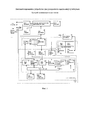
На фиг. 1 представлено автоматизированное устройство для ускоренного заряда аккумуляторных батарей асимметричным током (блок-схема).In FIG. 1 shows an automated device for accelerated charging of batteries with asymmetric current (block diagram).
Осуществление изобретенияThe implementation of the invention
На фиг. 1 изображена блок-схема устройства. Устройство включает силовую часть зарядного устройства (СЧЗУ) и систему управления зарядным устройством (СУЗУ). СУЗУ состоит из блока стабилизации 3 и блока ввода-вывода 5. Блок стабилизации состоит из микроконтроллера (МК) 4 и соединенных с ним блоком датчика напряжения 15, блоком датчика напряжения 16, блоком датчика тока 17, блоком индикации 25, блоком звуковой сигнализации 26. Блок МК 4 состоит из блока управления 24 и соединенных с ним блоком ШИМ 18, блоком сопряжения по интерфейсу SMbus 19, блоком аналого-цифрового преобразования (АЦП) 20, блоком усилителей 21, блоком задания алгоритма заряда 22, блоком сопряжения по интерфейсу I2C 23. Блок ввода-вывода 5 соединен с персональным компьютером 6. Блок МКУ 14 соединен с блоком сопряжения по интерфейсу SMbus 19. Питающее напряжение подается на блок фильтров 7. Выход блока фильтра 7 соединен с блоком нагрузки 10 и блоком регулируемого источника заряд-разрядного тока 8. Выход блока регулируемого источника заряд-разрядного тока 8 соединен с входом блока фильтра 9. Выход блока фильтра 9 соединен с блоком подключения АБ и самой АБ. Выход блока ШИМ 18 соединен с входом блока усилителей 11, выход которого соединен с блоком регулируемого источника заряд-разрядного тока 8.In FIG. 1 shows a block diagram of a device. The device includes the power part of the charger (CMS) and the control system of the charger (CMS). The control system consists of a
Устройство работает следующим образом.The device operates as follows.
При включении устройства блок МК 4 инициализирует записанную в блок задания алгоритма заряда 22 программу, которая устанавливает выходные сигналы портов ввода-вывода в начальное состояние, контролирует входные сигналы портов ввода-вывода и АЦП. Сигналы с выхода блока МК 4 запирают блок усилителей 11 во избежание открытия силовых элементов схемы 1 СЧЗУ. Блок ввода-вывода 5 служит для отображения информации на алфавитно-цифровом дисплее и управления устройством. Обмен информацией между блоком ввода-вывода 5 и блоком стабилизации 3 осуществляется по интерфейсу 12C. С помощью блока ввода-вывода 5 оператор вручную выбирает тип и режим для никель-кадмиевой, никель-металлогидридной или литий-ионной (без встроенного МКУ с интерфейсом SMBus) АБ. Режим заряда асимметричным током предусмотрен только для никель-кадмиевых и никель-металлогидридных АБ. Параметры заряда для выбранного типа АБ передаются в блок стабилизации 3. Блок управления 24 анализирует полученную информацию и выбирает из блока задания алгоритма заряда 22 алгоритм, соответствующий заряду данного типа батареи. При подключении АБ с МКУ зарядное устройство по интерфейсу SMBus считывает данные (токи, напряжения окончания заряда и т.д.) и в автоматическом режиме начинает процесс заряда. Заряд осуществляется в автоматическом режиме без участия оператора, все параметры заряда задает сама батарея. В процессе заряда параметры (емкость АБ, число циклов и т.д.), считанные из МКУ АБ, через блок стабилизации 3 передаются в блок ввода-вывода 5, где отображаются на алфавитно-цифровом дисплее (АЦД). При подключении батареи фотоэлектрической блок МК 4 через блок датчика напряжения 15 определяет наличие подключение к ЗУ последней. Алгоритм заряда от батареи фотоэлектрической реализуется по принципу поиска максимальной мощности путем коротких периодических изменений положения рабочей точки.When the device is turned on, the MK 4 unit initializes the program recorded in the charge
Если задан заряд асимметричным током (для никель-кадмиевой или никель-металлогидридной АБ) блок ввода-вывода 5 выдает параметры режима заряда в блок стабилизации 3 в соответствии с выбранным типом и режимом заряда АБ. Блок управления 24 выдает сигналы управления зарядом на блок ШИМ 18 и сигнал на блок индикации 25. Сигналы, поступающие с блока ШИМ 18 на блок усилителей 11 и далее на блок регулируемого источника заряд-разрядного тока 8, устанавливают амплитуды и длительности зарядных и разрядных импульсов согласно выбранному типу АБ. Блок регулируемого источника заряд-разрядного тока 8 является дуальным, т.е. обеспечивает протекания тока в двух направлениях - зарядного или разрядного. При формировании разрядного импульса энергия накапливается во входных конденсаторах блока фильтра, а затем используется для формирования зарядного импульса, т.е. осуществляется рекуперация энергии. Амплитуды зарядного и разрядного импульса контролируются с помощью сигналов, поступающих с блока датчика тока 17 на блок усилителей 21 и далее на блок АЦП 20. В ходе заряда контролируется напряжение АБ, сигнал с АБ через блок датчика напряжения 16 поступает на блок АЦП 20. По окончании процесса заряда блок управления 24 прекращает подачу сигналов управления на блок ШИМ 18, на выходах которого устанавливаются уровни, запирающие блок регулируемого источника заряд-разрядного тока 8, батарея отключается от зарядной цепи. Блок управления 24 подает сигнал в блоки индикации 25, звуковой сигнализации 26, ввода-вывода 5 о нормальном завершении процесса заряда.If the charge is specified by an asymmetric current (for nickel-cadmium or nickel-metal hydride AB), the input-
Если задан ускоренный режим (для никель-кадмиевой или никель-металлогидридной АБ) заряда постоянным током, то алгоритм заряда соответствует вышеописанному, но в процессе заряда блок регулируемого источника заряд-разрядного тока формирует только зарядный ток.If the accelerated mode (for nickel-cadmium or nickel-metal hydride AB) is set for direct current charging, then the charging algorithm corresponds to the above, but during the charging process, the unit of the regulated charge-discharge current source generates only the charging current.
Если задан стандартный режим (для никель-кадмиевой или никель-металлогидридной АБ) заряда постоянным током, блок управления 24 выдает сигналы управления разрядом на блок ШИМ 18 и сигналы свечения на блок индикации 25. Сигнал с блока ШИМ 18, поступающий на блок усилителей 11 и далее на блок регулируемого источника заряд-разрядного тока 8, устанавливает амплитуду разрядного тока согласно выбранному типу АБ. Амплитуда разрядного тока контролируется с помощью сигнала, поступающего с блока датчика тока 17 на блок АЦП 20. Энергия разряда гасится в блоке нагрузки 10, представляющем собой резистор и ключ. В ходе разряда в соответствии с алгоритмом контролируется напряжение АБ. По достижении конечного разрядного напряжения блок управления 24 прекращает подачу сигналов управления в блок ШИМ 18, на выходе которого устанавливается уровень, запирающий блок регулируемого источника заряд-разрядного тока 8. Далее блок управления 24 выдают сигналы управления зарядом на блок ШИМ 18. Сигналы, поступающие с блока ШИМ 18 на блок усилителей 11 и далее на блок регулируемого источника заряд-разрядного тока 8, устанавливают амплитуду зарядного тока согласно выбранному типу АБ. Амплитуда зарядного тока контролируются с помощью сигнала, поступающего с блока датчика тока 17 на блок усилителей 21 и далее на блок АЦП 20. В ходе заряда контролируется напряжение АБ, сигнал с АБ через блок датчика напряжения 16 поступает на блок АЦП 20. По окончании процесса заряда блок управления 24 прекращает подачу сигналов управления на блок ШИМ 18, на выходах которого устанавливаются уровни, запирающие блок регулируемого источника заряд-разрядного тока 8, батарея отключается от зарядной цепи. Блок управления 24 подает сигнал в блоки индикации 25, звуковой сигнализации 26, ввода-вывода 5 о нормальном завершении процесса заряда. If the standard mode (for nickel-cadmium or nickel-metal hydride AB) of a constant current charge is set, the
Если задан ускоренный режим заряда для литий-ионной АБ (без встроенного МКУ с интерфейсом SMBus), блок управления 24 выдает сигналы управления зарядом на блок ШИМ 18 и сигналы свечения на блок индикации 25. Заряд проходит в комбинированном режиме: вначале при постоянном токе до напряжения 4,2 В/элемент, затем при постоянном напряжении. Сигнал, поступающий с блока ШИМ 18 на блок усилителей 11 и далее на блок регулируемого источника заряд-разрядного тока 8, устанавливает амплитуду зарядного тока согласно выбранному типу АБ. Амплитуда зарядного тока контролируются с помощью сигнала, поступающего с блока датчика тока 17 на блок усилителей 21 и далее на блок АЦП 20. В ходе заряда контролируется напряжение АБ, сигнал с АБ через блок датчика напряжения 16 поступает на блок АЦП 20. При достижении напряжения 4,2 В/элемент блок регулируемого источника заряд-разрядного тока 8 переходит в режим стабилизации напряжения. Процесс заряда продолжается при спадающем токе. По окончании процесса заряда (прекращается при достижении минимального значения тока, задан в соответствии с выбранным типом АБ) блок управления 24 прекращает подачу сигналов управления на блок ШИМ 18, на выходах которого устанавливаются уровни, запирающие блок регулируемого источника заряд-разрядного тока 8, батарея отключается от зарядной цепи. Блок управления 24 подает сигнал в блоки индикации 25, звуковой сигнализации 26, ввода-вывода 5 о нормальном завершении процесса заряда.If the accelerated charge mode is set for a lithium-ion battery (without a built-in MCU with SMBus interface), the
При подключении литий-ионной АБ (со встроенным МКУ с интерфейсом SMbus) блок сопряжения по интерфейсу SMbus 19 считывает информацию с МКУ. Блок задания алгоритма заряда 22 формирует режим в соответствии с параметрами, считанными из МКУ АБ. Заряд осуществляется в автоматическом режиме. Параметры, считанные из МКУ АБ, передаются на блок ввода-вывода, где отображаются на блоке АЦД. Процесс заряда аналогичен вышеописанному для литий-ионной АБ.When connecting a lithium-ion battery (with built-in MCU with SMbus interface), the interface unit on the
Если подключена батарея фотоэлектрическая, на вход блока управления 24 поступает сигнал с входа блока датчика напряжения 15, сигнализирующий о наличии батареи фотоэлектрической. Для всех типов батарей, можно выбрать только ускоренный режим заряда постоянным током. Блок управления 24 выдает сигналы управления зарядом на блок ШИМ 18 и сигналы свечения на блок индикации 25. Сигнал, поступающий с блока ШИМ 18 на блок усилителей 17 и далее на блок регулируемого источника заряд-разрядного тока 8, устанавливает амплитуду зарядного тока согласно выбранному типу АБ. В случае нехватки энергии реализуется алгоритм заряда по принципу поиска максимальной мощности путем коротких периодических изменений положения рабочей точки. При недостаточной освещенности батареи фотоэлектрической - ток заряда не стабилизирован. В ходе заряда контролируется напряжение АБ, сигнал с АБ через блок датчика напряжения 16 поступает на блок АЦП 20. По окончаниипроцесса заряда блок управления 24 прекращает подачу сигналов управления на блок ШИМ 18, на выходах которого устанавливаются уровни, запирающие блок регулируемого источника заряд-разрядного тока, батарея отключается от зарядной цепи. Блок управления 24 подает сигнал в блоки индикации 25, звуковой сигнализации, ввода-вывода о нормальном завершении процесса заряда.If a photoelectric battery is connected, a signal from the input of the
Ведение в силовую часть зарядного устройства (СЧЗУ) блока регулируемого источника заряд-разрядного тока, построенного по принципу дуального преобразователя и имеющего регулировочную характеристику как повышающего, так и понижающего преобразователя при заряде и разряде приводит к исключению одновременного применения нескольких преобразователей, способных работать только как повышающий или понижающий, что приводит к уменьшение массы, габаритов и стоимости.Keeping in the power part of the charging device (SCZU) a block of an adjustable source of charge-discharge current, built on the principle of a dual converter and having the adjustment characteristic of both an increasing and decreasing converter when charging and discharging, eliminates the simultaneous use of several converters that can only work as an increasing or lowering, which leads to a decrease in weight, size and cost.
Введение блока сопряжения SMBus обеспечивает автоматический заряд литий-ионных АБ (при наличии МКУ с интерфейсом SMBus). При появлении новых АБ с аналогичным интерфейсом не потребуется перепрограммировать и перенастраивать ЗУ, поскольку все параметры заряда содержатся в МКУ АБ, ЗУ по интерфейсу SMBus считает параметры и установит АБ на заряд.The introduction of the SMBus interface unit provides automatic charging of lithium-ion batteries (in the presence of MCUs with the SMBus interface). When new batteries with a similar interface appear, it will not be necessary to reprogram and reconfigure the charger, since all the charge parameters are contained in the battery management center, the charger considers the parameters via the SMBus interface and sets the battery to charge.
Введение в систему алгоритма заряда по принципу поиска точки максимальной мощности позволило обеспечить заряд АБ от батареи фотоэлектрической.The introduction of a charge algorithm in the system according to the principle of searching for the maximum power point made it possible to ensure the battery charge from a photoelectric battery.
Введение блока сопряжения USB позволило обеспечить взаимодействие ЗУ с ПК. Данные об АБ (зарядно/разрядные графики напряжения, данные с МКУ АБ и т.д.) могут быть сохранены на ПК в базе данных для последующего анализа.The introduction of the USB interface unit allowed the memory to interact with the PC. Data on the battery (charge / discharge voltage graphs, data from the MCU of the battery, etc.) can be stored on a PC in a database for subsequent analysis.
Claims (1)
Priority Applications (1)
| Application Number | Priority Date | Filing Date | Title |
|---|---|---|---|
| RU2015137658A RU2613684C2 (en) | 2015-09-03 | 2015-09-03 | Automated system for fast charging the asymmetric current batteries |
Applications Claiming Priority (1)
| Application Number | Priority Date | Filing Date | Title |
|---|---|---|---|
| RU2015137658A RU2613684C2 (en) | 2015-09-03 | 2015-09-03 | Automated system for fast charging the asymmetric current batteries |
Publications (2)
| Publication Number | Publication Date |
|---|---|
| RU2015137658A RU2015137658A (en) | 2017-03-09 |
| RU2613684C2 true RU2613684C2 (en) | 2017-03-21 |
Family
ID=58453225
Family Applications (1)
| Application Number | Title | Priority Date | Filing Date |
|---|---|---|---|
| RU2015137658A RU2613684C2 (en) | 2015-09-03 | 2015-09-03 | Automated system for fast charging the asymmetric current batteries |
Country Status (1)
| Country | Link |
|---|---|
| RU (1) | RU2613684C2 (en) |
Cited By (1)
| Publication number | Priority date | Publication date | Assignee | Title |
|---|---|---|---|---|
| RU2679883C1 (en) * | 2018-02-13 | 2019-02-14 | Федеральное государственное бюджетное образовательное учреждение высшего образования "Национальный исследовательский Мордовский государственный университет им. Н.П. Огарёва" | Device for monitoring and managing the charge of batteries |
Citations (3)
| Publication number | Priority date | Publication date | Assignee | Title |
|---|---|---|---|---|
| US5905361A (en) * | 1994-09-01 | 1999-05-18 | Fujitsu Limited | Charging-and-discharging device, constant-voltage and constant-current control circuit, and electronic device |
| RU2318285C1 (en) * | 2006-06-30 | 2008-02-27 | Открытое акционерное общество "Всероссийский научно-исследовательский и проектно-конструкторский институт электровозостроения" (ОАО "ВЭлНИИ") | Automatic device for accelerated charge of storage batteries with asymmetric current |
| RU2319275C1 (en) * | 2006-08-15 | 2008-03-10 | Открытое акционерное общество "Всероссийский научно-исследовательский и проектно-конструкторский институт электровозостроения" (ОАО "ВЭлНИИ") | Computerized device for high-speed charge of storage batteries with asymmetric current |
-
2015
- 2015-09-03 RU RU2015137658A patent/RU2613684C2/en not_active IP Right Cessation
Patent Citations (3)
| Publication number | Priority date | Publication date | Assignee | Title |
|---|---|---|---|---|
| US5905361A (en) * | 1994-09-01 | 1999-05-18 | Fujitsu Limited | Charging-and-discharging device, constant-voltage and constant-current control circuit, and electronic device |
| RU2318285C1 (en) * | 2006-06-30 | 2008-02-27 | Открытое акционерное общество "Всероссийский научно-исследовательский и проектно-конструкторский институт электровозостроения" (ОАО "ВЭлНИИ") | Automatic device for accelerated charge of storage batteries with asymmetric current |
| RU2319275C1 (en) * | 2006-08-15 | 2008-03-10 | Открытое акционерное общество "Всероссийский научно-исследовательский и проектно-конструкторский институт электровозостроения" (ОАО "ВЭлНИИ") | Computerized device for high-speed charge of storage batteries with asymmetric current |
Cited By (1)
| Publication number | Priority date | Publication date | Assignee | Title |
|---|---|---|---|---|
| RU2679883C1 (en) * | 2018-02-13 | 2019-02-14 | Федеральное государственное бюджетное образовательное учреждение высшего образования "Национальный исследовательский Мордовский государственный университет им. Н.П. Огарёва" | Device for monitoring and managing the charge of batteries |
Also Published As
| Publication number | Publication date |
|---|---|
| RU2015137658A (en) | 2017-03-09 |
Similar Documents
| Publication | Publication Date | Title |
|---|---|---|
| EP3347939B1 (en) | Battery with a voltage regulation device | |
| EP3518377B1 (en) | Electronic cigarette, and power supply structure thereof | |
| KR0173961B1 (en) | Mode conversion type battery charging apparatus | |
| CN101604860B (en) | Battery management systems and method for charging battery pack with multiple batteries | |
| US20150189916A1 (en) | Electronic smoking device | |
| US20120025752A1 (en) | Battery charger | |
| EP3445422B1 (en) | Multi-mode power supply system for a portable infusion device | |
| CN106712159A (en) | Lithium battery fast charging and discharging device and lithium battery fast charging and discharging method | |
| KR20180087014A (en) | Battery pack, management method of the same, and vehicle comprisin the same | |
| CN104078716B (en) | Battery charging method and processor | |
| US20150130396A1 (en) | Mobile device solar powered charging apparatus, method, and system | |
| WO2019218316A1 (en) | Storage battery maintainer and method, and electronic device | |
| RU2613684C2 (en) | Automated system for fast charging the asymmetric current batteries | |
| US20210006087A1 (en) | Charging method and charger | |
| JP3104747U (en) | Solar battery charger | |
| CN204116873U (en) | Electronic cigarette controller | |
| CN210490543U (en) | Multi-stage energy storage element parallel charging and discharging system | |
| RU98071U1 (en) | AUTOMATIC CONTROL SYSTEM AND CHARGING BATTERIES | |
| RU2319275C1 (en) | Computerized device for high-speed charge of storage batteries with asymmetric current | |
| CN210578872U (en) | Solar-powered network camera system | |
| RU2318285C1 (en) | Automatic device for accelerated charge of storage batteries with asymmetric current | |
| KR101243694B1 (en) | Power storage apparatus comprising different storage battery type and solar streetlight using the same | |
| CN202930977U (en) | Lithium battery charger with temperature detection | |
| US20180324930A1 (en) | Wall switch base of an electric light | |
| CN107147170A (en) | A kind of power-supply management system and method |
Legal Events
| Date | Code | Title | Description |
|---|---|---|---|
| MM4A | The patent is invalid due to non-payment of fees |
Effective date: 20170904 |