RU2611156C2 - Metal can capping method with laminated cover and device for such method implementation - Google Patents
Metal can capping method with laminated cover and device for such method implementation Download PDFInfo
- Publication number
- RU2611156C2 RU2611156C2 RU2014124037A RU2014124037A RU2611156C2 RU 2611156 C2 RU2611156 C2 RU 2611156C2 RU 2014124037 A RU2014124037 A RU 2014124037A RU 2014124037 A RU2014124037 A RU 2014124037A RU 2611156 C2 RU2611156 C2 RU 2611156C2
- Authority
- RU
- Russia
- Prior art keywords
- flange
- coil
- peelable
- lid
- heating
- Prior art date
Links
Images

Classifications
-
- B—PERFORMING OPERATIONS; TRANSPORTING
- B65—CONVEYING; PACKING; STORING; HANDLING THIN OR FILAMENTARY MATERIAL
- B65B—MACHINES, APPARATUS OR DEVICES FOR, OR METHODS OF, PACKAGING ARTICLES OR MATERIALS; UNPACKING
- B65B51/00—Devices for, or methods of, sealing or securing package folds or closures; Devices for gathering or twisting wrappers, or necks of bags
- B65B51/10—Applying or generating heat or pressure or combinations thereof
- B65B51/22—Applying or generating heat or pressure or combinations thereof by friction or ultrasonic or high-frequency electrical means, i.e. by friction or ultrasonic or induction welding
- B65B51/227—Applying or generating heat or pressure or combinations thereof by friction or ultrasonic or high-frequency electrical means, i.e. by friction or ultrasonic or induction welding by induction welding
-
- B—PERFORMING OPERATIONS; TRANSPORTING
- B29—WORKING OF PLASTICS; WORKING OF SUBSTANCES IN A PLASTIC STATE IN GENERAL
- B29C—SHAPING OR JOINING OF PLASTICS; SHAPING OF MATERIAL IN A PLASTIC STATE, NOT OTHERWISE PROVIDED FOR; AFTER-TREATMENT OF THE SHAPED PRODUCTS, e.g. REPAIRING
- B29C65/00—Joining or sealing of preformed parts, e.g. welding of plastics materials; Apparatus therefor
- B29C65/02—Joining or sealing of preformed parts, e.g. welding of plastics materials; Apparatus therefor by heating, with or without pressure
- B29C65/44—Joining a heated non plastics element to a plastics element
- B29C65/46—Joining a heated non plastics element to a plastics element heated by induction
-
- B—PERFORMING OPERATIONS; TRANSPORTING
- B65—CONVEYING; PACKING; STORING; HANDLING THIN OR FILAMENTARY MATERIAL
- B65B—MACHINES, APPARATUS OR DEVICES FOR, OR METHODS OF, PACKAGING ARTICLES OR MATERIALS; UNPACKING
- B65B7/00—Closing containers or receptacles after filling
- B65B7/16—Closing semi-rigid or rigid containers or receptacles not deformed by, or not taking-up shape of, contents, e.g. boxes or cartons
- B65B7/28—Closing semi-rigid or rigid containers or receptacles not deformed by, or not taking-up shape of, contents, e.g. boxes or cartons by applying separate preformed closures, e.g. lids, covers
- B65B7/2842—Securing closures on containers
- B65B7/2878—Securing closures on containers by heat-sealing
-
- B—PERFORMING OPERATIONS; TRANSPORTING
- B65—CONVEYING; PACKING; STORING; HANDLING THIN OR FILAMENTARY MATERIAL
- B65B—MACHINES, APPARATUS OR DEVICES FOR, OR METHODS OF, PACKAGING ARTICLES OR MATERIALS; UNPACKING
- B65B7/00—Closing containers or receptacles after filling
- B65B7/16—Closing semi-rigid or rigid containers or receptacles not deformed by, or not taking-up shape of, contents, e.g. boxes or cartons
- B65B7/28—Closing semi-rigid or rigid containers or receptacles not deformed by, or not taking-up shape of, contents, e.g. boxes or cartons by applying separate preformed closures, e.g. lids, covers
- B65B7/2842—Securing closures on containers
- B65B7/2885—Securing closures on containers by heat-shrinking
-
- H—ELECTRICITY
- H05—ELECTRIC TECHNIQUES NOT OTHERWISE PROVIDED FOR
- H05B—ELECTRIC HEATING; ELECTRIC LIGHT SOURCES NOT OTHERWISE PROVIDED FOR; CIRCUIT ARRANGEMENTS FOR ELECTRIC LIGHT SOURCES, IN GENERAL
- H05B6/00—Heating by electric, magnetic or electromagnetic fields
- H05B6/02—Induction heating
- H05B6/10—Induction heating apparatus, other than furnaces, for specific applications
- H05B6/101—Induction heating apparatus, other than furnaces, for specific applications for local heating of metal pieces
-
- H—ELECTRICITY
- H05—ELECTRIC TECHNIQUES NOT OTHERWISE PROVIDED FOR
- H05B—ELECTRIC HEATING; ELECTRIC LIGHT SOURCES NOT OTHERWISE PROVIDED FOR; CIRCUIT ARRANGEMENTS FOR ELECTRIC LIGHT SOURCES, IN GENERAL
- H05B6/00—Heating by electric, magnetic or electromagnetic fields
- H05B6/02—Induction heating
- H05B6/36—Coil arrangements
- H05B6/38—Coil arrangements specially adapted for fitting into hollow spaces of workpieces
-
- H—ELECTRICITY
- H05—ELECTRIC TECHNIQUES NOT OTHERWISE PROVIDED FOR
- H05B—ELECTRIC HEATING; ELECTRIC LIGHT SOURCES NOT OTHERWISE PROVIDED FOR; CIRCUIT ARRANGEMENTS FOR ELECTRIC LIGHT SOURCES, IN GENERAL
- H05B6/00—Heating by electric, magnetic or electromagnetic fields
- H05B6/02—Induction heating
- H05B6/36—Coil arrangements
- H05B6/44—Coil arrangements having more than one coil or coil segment
-
- B—PERFORMING OPERATIONS; TRANSPORTING
- B29—WORKING OF PLASTICS; WORKING OF SUBSTANCES IN A PLASTIC STATE IN GENERAL
- B29C—SHAPING OR JOINING OF PLASTICS; SHAPING OF MATERIAL IN A PLASTIC STATE, NOT OTHERWISE PROVIDED FOR; AFTER-TREATMENT OF THE SHAPED PRODUCTS, e.g. REPAIRING
- B29C65/00—Joining or sealing of preformed parts, e.g. welding of plastics materials; Apparatus therefor
- B29C65/76—Making non-permanent or releasable joints
-
- B—PERFORMING OPERATIONS; TRANSPORTING
- B29—WORKING OF PLASTICS; WORKING OF SUBSTANCES IN A PLASTIC STATE IN GENERAL
- B29C—SHAPING OR JOINING OF PLASTICS; SHAPING OF MATERIAL IN A PLASTIC STATE, NOT OTHERWISE PROVIDED FOR; AFTER-TREATMENT OF THE SHAPED PRODUCTS, e.g. REPAIRING
- B29C66/00—General aspects of processes or apparatus for joining preformed parts
- B29C66/01—General aspects dealing with the joint area or with the area to be joined
- B29C66/05—Particular design of joint configurations
- B29C66/10—Particular design of joint configurations particular design of the joint cross-sections
- B29C66/11—Joint cross-sections comprising a single joint-segment, i.e. one of the parts to be joined comprising a single joint-segment in the joint cross-section
- B29C66/112—Single lapped joints
-
- B—PERFORMING OPERATIONS; TRANSPORTING
- B29—WORKING OF PLASTICS; WORKING OF SUBSTANCES IN A PLASTIC STATE IN GENERAL
- B29C—SHAPING OR JOINING OF PLASTICS; SHAPING OF MATERIAL IN A PLASTIC STATE, NOT OTHERWISE PROVIDED FOR; AFTER-TREATMENT OF THE SHAPED PRODUCTS, e.g. REPAIRING
- B29C66/00—General aspects of processes or apparatus for joining preformed parts
- B29C66/01—General aspects dealing with the joint area or with the area to be joined
- B29C66/05—Particular design of joint configurations
- B29C66/10—Particular design of joint configurations particular design of the joint cross-sections
- B29C66/13—Single flanged joints; Fin-type joints; Single hem joints; Edge joints; Interpenetrating fingered joints; Other specific particular designs of joint cross-sections not provided for in groups B29C66/11 - B29C66/12
- B29C66/131—Single flanged joints, i.e. one of the parts to be joined being rigid and flanged in the joint area
-
- B—PERFORMING OPERATIONS; TRANSPORTING
- B29—WORKING OF PLASTICS; WORKING OF SUBSTANCES IN A PLASTIC STATE IN GENERAL
- B29C—SHAPING OR JOINING OF PLASTICS; SHAPING OF MATERIAL IN A PLASTIC STATE, NOT OTHERWISE PROVIDED FOR; AFTER-TREATMENT OF THE SHAPED PRODUCTS, e.g. REPAIRING
- B29C66/00—General aspects of processes or apparatus for joining preformed parts
- B29C66/50—General aspects of joining tubular articles; General aspects of joining long products, i.e. bars or profiled elements; General aspects of joining single elements to tubular articles, hollow articles or bars; General aspects of joining several hollow-preforms to form hollow or tubular articles
- B29C66/51—Joining tubular articles, profiled elements or bars; Joining single elements to tubular articles, hollow articles or bars; Joining several hollow-preforms to form hollow or tubular articles
- B29C66/53—Joining single elements to tubular articles, hollow articles or bars
- B29C66/534—Joining single elements to open ends of tubular or hollow articles or to the ends of bars
- B29C66/5346—Joining single elements to open ends of tubular or hollow articles or to the ends of bars said single elements being substantially flat
- B29C66/53461—Joining single elements to open ends of tubular or hollow articles or to the ends of bars said single elements being substantially flat joining substantially flat covers and/or substantially flat bottoms to open ends of container bodies
-
- B—PERFORMING OPERATIONS; TRANSPORTING
- B29—WORKING OF PLASTICS; WORKING OF SUBSTANCES IN A PLASTIC STATE IN GENERAL
- B29C—SHAPING OR JOINING OF PLASTICS; SHAPING OF MATERIAL IN A PLASTIC STATE, NOT OTHERWISE PROVIDED FOR; AFTER-TREATMENT OF THE SHAPED PRODUCTS, e.g. REPAIRING
- B29C66/00—General aspects of processes or apparatus for joining preformed parts
- B29C66/70—General aspects of processes or apparatus for joining preformed parts characterised by the composition, physical properties or the structure of the material of the parts to be joined; Joining with non-plastics material
- B29C66/72—General aspects of processes or apparatus for joining preformed parts characterised by the composition, physical properties or the structure of the material of the parts to be joined; Joining with non-plastics material characterised by the structure of the material of the parts to be joined
- B29C66/723—General aspects of processes or apparatus for joining preformed parts characterised by the composition, physical properties or the structure of the material of the parts to be joined; Joining with non-plastics material characterised by the structure of the material of the parts to be joined being multi-layered
-
- B—PERFORMING OPERATIONS; TRANSPORTING
- B29—WORKING OF PLASTICS; WORKING OF SUBSTANCES IN A PLASTIC STATE IN GENERAL
- B29C—SHAPING OR JOINING OF PLASTICS; SHAPING OF MATERIAL IN A PLASTIC STATE, NOT OTHERWISE PROVIDED FOR; AFTER-TREATMENT OF THE SHAPED PRODUCTS, e.g. REPAIRING
- B29C66/00—General aspects of processes or apparatus for joining preformed parts
- B29C66/70—General aspects of processes or apparatus for joining preformed parts characterised by the composition, physical properties or the structure of the material of the parts to be joined; Joining with non-plastics material
- B29C66/74—Joining plastics material to non-plastics material
- B29C66/742—Joining plastics material to non-plastics material to metals or their alloys
-
- B—PERFORMING OPERATIONS; TRANSPORTING
- B29—WORKING OF PLASTICS; WORKING OF SUBSTANCES IN A PLASTIC STATE IN GENERAL
- B29C—SHAPING OR JOINING OF PLASTICS; SHAPING OF MATERIAL IN A PLASTIC STATE, NOT OTHERWISE PROVIDED FOR; AFTER-TREATMENT OF THE SHAPED PRODUCTS, e.g. REPAIRING
- B29C66/00—General aspects of processes or apparatus for joining preformed parts
- B29C66/80—General aspects of machine operations or constructions and parts thereof
- B29C66/83—General aspects of machine operations or constructions and parts thereof characterised by the movement of the joining or pressing tools
- B29C66/832—Reciprocating joining or pressing tools
- B29C66/8322—Joining or pressing tools reciprocating along one axis
-
- B—PERFORMING OPERATIONS; TRANSPORTING
- B29—WORKING OF PLASTICS; WORKING OF SUBSTANCES IN A PLASTIC STATE IN GENERAL
- B29L—INDEXING SCHEME ASSOCIATED WITH SUBCLASS B29C, RELATING TO PARTICULAR ARTICLES
- B29L2022/00—Hollow articles
-
- B—PERFORMING OPERATIONS; TRANSPORTING
- B29—WORKING OF PLASTICS; WORKING OF SUBSTANCES IN A PLASTIC STATE IN GENERAL
- B29L—INDEXING SCHEME ASSOCIATED WITH SUBCLASS B29C, RELATING TO PARTICULAR ARTICLES
- B29L2031/00—Other particular articles
- B29L2031/56—Stoppers or lids for bottles, jars, or the like, e.g. closures
- B29L2031/565—Stoppers or lids for bottles, jars, or the like, e.g. closures for containers
Landscapes
- Engineering & Computer Science (AREA)
- Mechanical Engineering (AREA)
- Physics & Mathematics (AREA)
- Electromagnetism (AREA)
- Closing Of Containers (AREA)
- General Induction Heating (AREA)
- Packages (AREA)
- Rigid Containers With Two Or More Constituent Elements (AREA)
- Package Closures (AREA)
Abstract
Description
Область техникиTechnical field
Настоящее изобретение относится к металлическим банкам с отслаиваемыми крышками и, более конкретно, к способу герметичного прикрепления отслаиваемых крышек к металлическим банкам, использующему индукционный нагрев.The present invention relates to metal cans with peelable lids and, more particularly, to a method of hermetically attaching peelable lids to metal banks using induction heating.
Уровень техникиState of the art
Многие контейнеры, применяемые для хранения пищевых продуктов, снабжены отслаиваемой крышкой, легко отделяемой перед первым использованием продукта потребителем. Назначение таких отслаиваемых крышек заключается как в герметизации выходного отверстия контейнера, так и в выполнении функции надежного индикатора вскрытия банки. Использование отслаиваемой крышки лежит в основе легкого способа открывания контейнера без применения специальных инструментов, таких как ножницы или консервные ножи.Many containers used for food storage have a peelable lid that can be easily detached before the consumer first uses the product. The purpose of such peel-off lids is both to seal the outlet of the container and to act as a reliable indicator of opening the can. The use of a peelable lid is at the heart of an easy way to open a container without using special tools such as scissors or can openers.
Контейнеры с отслаиваемыми крышками можно изготавливать из множества различных материалов, в число которых входят стекло, картон, пластик и металл. Картонные контейнеры в некоторых ситуациях могут быть пригодными для хранения пищевых продуктов, однако, для многих конкретных рынков сбыта, например, в странах с относительно жарким и/или влажным климатом они могут оказаться непригодными. Уязвимость по отношению к агрессивному воздействию вредителей (например мышей и крыс) и относительная непрочность также могут сделать картонные контейнеры непригодными для многих применений. Некоторые из тех же проблем возникают также для пластиковых и стеклянных контейнеров, но многие из этих вопросов находят свое решение при использовании металлических контейнеров (банок).Peelable containers can be made from a variety of different materials, including glass, cardboard, plastic and metal. Cardboard containers may be suitable for food storage in some situations, however, they may not be suitable for many specific markets, such as in countries with relatively hot and / or humid climates. Vulnerability to the aggressive effects of pests (e.g. mice and rats) and relative fragility can also make cardboard containers unsuitable for many applications. Some of the same problems also arise for plastic and glass containers, but many of these issues find their solution when using metal containers (cans).
Банки, предназначенные для применения в специализированных сегментах рынка, например в сфере детских смесей, должны удовлетворять строгим стандартам безопасности. Это может создать проблемы при изготовлении металлической банки с отслаиваемой крышкой, в типичном варианте выполненной из фольги. В частности, требуется, чтобы банка, используемая для хранения порошкообразных детских смесей, сохраняла герметичность своего соединения с отслаиваемой крышкой даже при хранении в течение более трех месяцев при высоких температурах, таких как 45°С, и при перепаде давления 70 кПа между внутренним объемом банки и ее окружением.Banks intended for use in specialized market segments, for example in the area of infant formula, must meet strict safety standards. This can create problems in the manufacture of a metal can with a peelable lid, typically made of foil. In particular, it is required that the can used for storing powdered infant formulas maintains its tightness with the peelable lid even when stored for more than three months at high temperatures, such as 45 ° C, and at a pressure drop of 70 kPa between the internal volume of the can and her surroundings.
В типичном варианте герметичное уплотнение между отслаиваемой крышкой из фольги и фланцем или кромкой металлической банки, направленным (направленной) внутрь и имеющим (имеющей) соответствующую конфигурацию, обеспечивают, на первой операции, нагревом герметизирующей поверхности фланца или кромки. Эту поверхность или противолежащую ей герметизирующую поверхность крышки покрывают связывающим материалом, которым обычно является лак или полимер. Затем на фланец накладывают крышку из фольги, а герметизацию обеспечивают воздействием комбинации тепла и давления, прикладываемых к установленной на свое место крышке.Typically, a tight seal between a peelable foil lid and a flange or edge of a metal can directed (directed) inward and having (having) an appropriate configuration is provided, in a first step, by heating the sealing surface of the flange or edge. This surface or the opposite sealing surface of the lid is coated with a bonding material, which is usually a varnish or polymer. Then, a foil lid is placed on the flange, and the sealing is ensured by the combination of heat and pressure applied to the lid in place.
Если заполненная герметизированная банка предназначена для дальнейшей обработки с целью варки или какого-то другого теплового воздействия на ее содержимое, предусмотрена возможность нанести на внутреннюю поверхность банки и на материал крышки полипропиленовые покрытия, которые сплавляются одно с другим, образуя герметичное уплотнение. Полученные в результате уплотнения способны выдерживать экстремальные условия обработки, такие как комбинация высокой температуры (типично 120°С или выше) и давления на крышку.If the filled sealed can is intended for further processing for the purpose of cooking or some other thermal effect on its contents, it is possible to apply polypropylene coatings on the inner surface of the can and on the lid material, which are fused with each other, forming a tight seal. The resulting seals are able to withstand extreme processing conditions, such as a combination of high temperature (typically 120 ° C or higher) and pressure on the cover.
Повышенную температуру фланца можно обеспечить, используя резистивный или индукционный нагрев. В первом случае тепло передается на металлическую банку через непосредственный контакт с ней, а в случае индукционного нагрева через электромагнитную индукционную катушку пропускают переменный ток высокой частоты для создания электромагнитного поля. Катушку устанавливают так, чтобы она охватывала банку снаружи, в результате чего банка и, конкретно, ее участок, окружающий фланец, оказываются внутри индуцированного осевого электромагнитного поля. Вихревые токи, образующиеся во фланце и в окружающей его зоне банки, обеспечивают быстрый нагрев фланца. Индукционный нагрев по сравнению с резистивным в общем случае имеет преимущества, заключающиеся в том, что у него длительности нагрева короче и что не требуется непосредственный контакт с банкой (т.е. с одной и той же настройкой устройства индукционного нагрева можно обрабатывать банки различной формы).Elevated flange temperatures can be achieved using resistive or induction heating. In the first case, heat is transferred to the metal can through direct contact with it, and in the case of induction heating, an alternating current of high frequency is passed through an electromagnetic induction coil to create an electromagnetic field. The coil is mounted so that it covers the can from the outside, as a result of which the can and, in particular, its portion surrounding the flange are inside the induced axial electromagnetic field. The eddy currents generated in the flange and in the surrounding area of the can provide rapid heating of the flange. Induction heating in comparison with resistive heating generally has advantages in that it has shorter heating times and that direct contact with the can is not required (i.e., cans of various shapes can be processed with the same setting of the induction heating device) .
Для некоторых применений желательно установить крышку из фольги в промежуточное положение по высоте корпуса банки, разделив таким образом корпус на два отделения. Герметичное отделение, расположенное под крышкой из фольги, используют для хранения пищевого продукта, а в отделение, расположенное над этой крышкой, можно поместить какой-то другой предмет, например пластиковую ложку.For some applications, it is desirable to install the foil lid in an intermediate position along the height of the can body, thereby dividing the body into two compartments. A sealed compartment located under the foil lid is used to store food, and in the compartment located above this lid, you can put some other object, such as a plastic spoon.
Верхнее отверстие банки может быть закрыто пластиковой крышкой или другим подобным средством. Однако у банок, причем в особенности у банок этой конфигурации, известные режимы нагрева могут инициировать заметное повреждение внешнего вида, вызванное высокими температурами, до которых приходится нагревать наружную поверхность банки, чтобы довести температуру герметизирующей поверхности фланца до уровня, требуемого для получения герметичного соединения. В типичном случае, поскольку в интервале времени между исходным нагревом и наложением крышки из фольги фланец немного охладится, герметизирующая поверхность должна быть нагрета до температуры, существенно превышающей заданную. В добавление к сказанному, т.к. тепло к фланцу переносится с наружной поверхности банки, эта поверхность должна быть нагрета до избыточной температуры. Для нагрева связывающего материала, которому требуется температура примерно 160°С, фланец необходимо нагреть до 200°С, но за это время температура наружной поверхности может выйти на уровень 280°С. Требуемая для наружной поверхности температура такова, что может произойти оплавление этой поверхности, проявляющееся видимым образом, например, как изменение ее цвета.The top opening of the can may be covered with a plastic lid or other similar means. However, for cans, and in particular for cans of this configuration, known heating conditions can initiate noticeable damage to the appearance caused by high temperatures, to which it is necessary to heat the outer surface of the can to bring the temperature of the sealing surface of the flange to the level required to obtain a tight connection. In a typical case, since the flange cools slightly in the time interval between the initial heating and the application of the foil lid, the sealing surface must be heated to a temperature significantly higher than the set value. In addition to the above, since heat is transferred to the flange from the outer surface of the can; this surface must be heated to an excessive temperature. To heat the binder, which requires a temperature of approximately 160 ° C, the flange must be heated to 200 ° C, but during this time the temperature of the outer surface can reach a level of 280 ° C. The temperature required for the outer surface is such that a fusion of this surface can occur, manifesting itself in a visible manner, for example, as a change in its color.
Одно из возможных решений перечисленных проблем заключается в применении связывающего материала такого типа, который выполняет свою функцию при более низкой температуре по сравнению с материалами, обычно используемыми для этой цели. Например, может быть применен связывающий материал, затвердевающий при 90°С. В таком варианте отпадает необходимость в избыточном нагреве наружной поверхности банки, однако, такие банки стали бы непригодными для продажи на рынках стран с жарким климатом.One of the possible solutions to these problems is to use a binder of the type that performs its function at a lower temperature compared to materials commonly used for this purpose. For example, a binder material hardening at 90 ° C may be used. In this embodiment, there is no need for excessive heating of the outer surface of the can, however, such cans would become unsuitable for sale in the markets of countries with hot climates.
Раскрытие изобретенияDisclosure of invention
Задача, на решение которой направлено изобретение, сводится к преодолению или по меньшей мере ослаблению недостатков известных систем индукционного нагрева, которые обычно применяют для герметичного прикрепления отслаиваемой крышки внутри корпуса банки.The problem to which the invention is directed, is to overcome or at least mitigate the disadvantages of the known induction heating systems, which are usually used to tightly attach the peelable lid inside the can body.
Согласно первому аспекту изобретения предлагается способ герметичного прикрепления отслаиваемой крышки к фланцу металлического корпуса банки, выступающему внутрь корпуса и проходящему по всему его периметру. Способ включает операции, на которых вводят индукционную катушки в корпус банки и пропускают через катушку переменный ток, нагревающий фланец. Затем индукционную катушку выводят из корпуса банки и накладывают на фланецAccording to a first aspect of the invention, there is provided a method for hermetically attaching a peelable lid to a flange of a metal can body protruding into the body and extending around its perimeter. The method includes operations in which an induction coil is introduced into the can body and an alternating current heating the flange is passed through the coil. Then the induction coil is removed from the can body and placed on the flange
отслаиваемую крышку, причем остаточное тепло во фланце обеспечивает герметичное прикрепление крышки к фланцу или способствует такому прикреплению.peelable cover, and the residual heat in the flange ensures tight attachment of the cover to the flange or contributes to such attachment.
Преимущество по меньшей мере некоторых вариантов изобретения заключается в том, что при наличии возможности нагреть фланец до требуемой температуры наружная стенка банки не перегревается, и тем самым предотвращается оплавление олова у наружной поверхности и, соответственно, ухудшение этой поверхности.An advantage of at least some embodiments of the invention is that if it is possible to heat the flange to the desired temperature, the outer wall of the can is not overheated, and thereby tin fusion at the outer surface and, accordingly, deterioration of this surface are prevented.
Способ может включать установку дополнительной индукционной катушки, которая охватывает наружную сторону корпуса банки и через которую, по существу, одновременно с операцией пропускания переменного тока по внутренней катушке пропускают переменный ток, дополнительно нагревающий фланец. Первая и вторая катушки могут запитываться совместно или отдельно одна от другой.The method may include installing an additional induction coil, which covers the outer side of the can body and through which, essentially simultaneously with the operation of passing alternating current, an alternating current is passed through the inner coil, further heating the flange. The first and second coils can be powered together or separately from one another.
В некоторых вариантах между отслаиваемой крышкой и фланцем банки можно нанести связывающий материал. В других вариантах его можно нанести на герметизирующую поверхность фланца перед наложением отслаиваемой крышки на фланец. Возможны и варианты с нанесением связывающего материала на герметизирующую поверхность отслаиваемой крышки перед наложением на фланец.In some embodiments, a bonding material may be applied between the peelable lid and the can flange. In other embodiments, it can be applied to the sealing surface of the flange before applying a peelable cover to the flange. There are also options with applying a bonding material to the sealing surface of the peelable lid before applying to the flange.
В некоторых вариантах фланец расположен в промежуточном положении по высоте корпуса банки, так что герметичное прикрепление отслаиваемой крышки к фланцу разделяет корпус банки на верхнее и нижнее отделения.In some embodiments, the flange is located in an intermediate position along the height of the can body, so that the tight attachment of the peelable lid to the flange separates the can body into the upper and lower compartments.
Согласно второму аспекту изобретения предлагается нагревательная система, предназначенная для применения в технологической линии изготовления банок и содержащая индукционную катушку, вводимую в корпус банки, и блок питания, обеспечивающий питание катушки во время ее нахождения в корпусе банки.According to a second aspect of the invention, there is provided a heating system for use in a can manufacturing line and comprising an induction coil introduced into the can body and a power supply unit providing power to the coil while it is in the can body.
Предлагаемая нагревательная система может содержать дополнительную катушку, предназначенную для размещения вокруг наружной стороны корпуса банки, причем конструкция блока питания позволяет подавать питание на эту катушку, когда она находится в своем рабочем положении. Предусмотрена возможность механически соединить обе катушки одну с другой в виде единого функционального блока, т.е. так, чтобы для установки катушек в требуемое положение относительно корпуса банки данный корпус можно было перемещать по отношению к данному блоку.The proposed heating system may include an additional coil designed to be placed around the outside of the can body, and the design of the power unit allows you to supply power to this coil when it is in its working position. It is possible to mechanically connect both coils to one another as a single functional unit, i.e. so that to install the coils in the required position relative to the can body, this body can be moved relative to this unit.
Краткое описание чертежейBrief Description of the Drawings
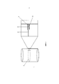
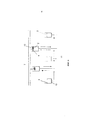
Фиг. 1 схематично иллюстрирует металлическую банку, разделенную на два отделения отслаиваемой крышкой из фольги, причем отдельно, в увеличенном FIG. 1 schematically illustrates a metal can divided into two compartments with a peelable foil lid, separately, enlarged
масштабе, показаны такие части банки, как фланец, его герметизирующая поверхность, связывающий материал и отслаиваемая крышка.scale, such parts of the can are shown as a flange, its sealing surface, a bonding material and a peelable lid.
Фиг. 2 иллюстрирует, в перспективном изображении, металлическую банку, для нагрева герметизирующего фланца установленную внутри индукционной катушки.FIG. 2 illustrates, in a perspective view, a metal can for heating a sealing flange mounted inside an induction coil.
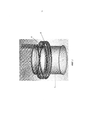
Фиг. 3 иллюстрирует, в перспективном изображении, систему нагрева фланца, которая содержит индукционную катушку, установленную внутри металлической банки.FIG. 3 illustrates, in a perspective view, a flange heating system that includes an induction coil mounted inside a metal can.
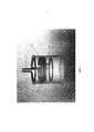
Фиг. 4 иллюстрирует, в перспективном изображении, альтернативную систему нагрева фланца, которая содержит две индукционные катушки, позиционированные внутри и снаружи банки.FIG. 4 illustrates, in a perspective view, an alternative flange heating system that comprises two induction coils positioned inside and outside the can.
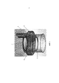
Фиг. 5 иллюстрирует, в перспективном изображении, еще одну альтернативную систему нагрева фланца.FIG. 5 illustrates, in a perspective view, another alternative flange heating system.
Фиг. 6 схематично иллюстрирует технологическую линию, используемую для герметичного прикрепления крышек из фольги к корпусам металлических банок.FIG. 6 schematically illustrates a production line used to seal foil lids to metal can cases.
Осуществление изобретенияThe implementation of the invention
Потребителям герметизированные отслаиваемые крышки предоставляют возможность воспользоваться легким способом открывания контейнера, обеспечивающим как удобство, так и безопасность. Более того, как показано на фиг. 1, отслаиваемые крышки 2 можно использовать для разделения корпуса банки 1 на два отделения. В таком варианте предусмотрена возможность сформировать сам корпус банки 1, складывая плоский лист и выполняя продольный шов или обрабатывая выдавливанием круглый диск так, чтобы сформировался цилиндр, выполненный заодно с основанием. На фиг. 1 проиллюстрирована также, в сечении, в увеличенном масштабе, зона, в которой крышка посредством связывающего материала 3 герметично прикрепляется к верхней герметизирующей поверхности 5 фланца 4, выступающего внутрь. Сама банка 1 в типичном варианте выполнена из луженого листа, а ее фланец 4 сформирован вдавливанием в кольцевую канавку, проходящую по всему периметру банки, и последующим приложением к банке осевого сжимающего усилия, сплющивающего канавку. Обычно крышку 2 формируют, на выбор, из металлической фольги, пластика или бумажного материала.Sealed peelable lids provide consumers with an easy way to open the container, providing both convenience and safety. Moreover, as shown in FIG. 1,
Как указывалось выше, чтобы герметично прикрепить крышку 2 к фланцу 4 корпуса банки 1, к данному фланцу можно подвести тепло, полученное с использованием индукционного нагрева. Однако стандартные приемы индукционного нагрева, использующие единственную наружную катушку 6 (см., например, фиг. 2), могут привести к оплавлению олова на наружной поверхности банки или к другим эффектам, вызывающим визуально наблюдаемое повреждение поверхности. ПоэтомуAs mentioned above, in order to tightly attach the
желательно разработать способ герметичного прикрепления отслаиваемой крышки 2 к фланцу 4 корпуса банки 1, направляющий тепло к фланцу 4, но в то же время уменьшающий степень нагрева наружной поверхности банки.it is desirable to develop a method for hermetically attaching a
Данная задача решается посредством системы нагрева фланца, проиллюстрированной на фиг. 3 и содержащей индукционную катушку 7. Банку 1 поднимают и опускают относительно системы нагрева фланца, т.е. во время нагрева индукционная катушка 7 вводится во внутреннюю зону металлического корпуса банки 1, прилегающую к фланцу 4, а затем, после нагрева, выводится из банки 1. При введенной в банку катушке зазор между катушкой и фланцем относительно невелик и имеет, например, размер порядка 1 мм. Такой зазор достаточен, чтобы катушку можно было перемещать в банку и из банки с высокими скоростями, обязательными для технологической линии.This problem is solved by the flange heating system illustrated in FIG. 3 and comprising an
Вопреки существующим представлениям и практическому опыту было показано, что для герметичного прикрепления крышки 2 к фланцу 4 катушка, введенная в банку 1, по сравнению с катушкой, установленной вокруг наружной стороны банки, более эффективна для генерирования достаточного тепла в примыкающей к ней зоне банки. При этом предлагаемый способ индукционного нагрева способен сфокусировать нагревательный эффект на выступающем внутрь фланце 4, удерживая в то же время температуру наружной стенки на более низком уровне и тем самым предотвращая оплавление олова и разрушение декоративной отделки на наружной стенке.Contrary to existing ideas and practical experience, it was shown that for tightly attaching the
Во втором варианте осуществления, проиллюстрированном на фиг. 4, система нагрева фланца содержит две индукционные катушки, запитываемые отдельно одна от другой, а именно внутреннюю катушку 7 и наружную катушку 9. Из них внутренняя катушка 7 позиционирована внутри наружной катушки 9 на одной оси с ней. Банку 1 поднимают и опускают по отношению к системе нагрева фланца 4 таким образом, чтобы во время его нагрева внутренняя и наружная индукционные катушки 7, 9 находились рядом с фланцем, полностью охватывая, соответственно, внутренний и наружный периметры банки 1. В этом варианте осуществления наружная индукционная катушка 9 выполняет свою функцию, нагревая фланец 4 через наружную поверхность стенки до температуры, не доходящей до уровня, на котором в другой ситуации могли бы произойти оплавление олова и разрушение декоративной отделки. Дополнительное тепло, требуемое для нагрева фланца 4 до желаемой температуры, индуцируется внутренней индукционной катушкой 7. Электромагнитные поля, формируемые наружной и внутренней индукционными катушками, перекрываются у фланца 4, вызывая совокупный эффект нагрева. Данный вариант осуществления In the second embodiment illustrated in FIG. 4, the flange heating system comprises two induction coils, fed separately from one another, namely the
предназначен для использования в тех ситуациях, в которых необходимо нагреть фланец 4 с особенно высокой скоростью.it is intended for use in those situations in which it is necessary to heat the
В третьем варианте, проиллюстрированном на фиг. 5, система нагрева фланца содержит единственную индукционную катушку 10 с внутренними витками и наружными витками. Когда систему нагрева фланца подводят к банке 1, внутренние витки катушки позиционируются внутри банки, а наружные - снаружи.In the third embodiment illustrated in FIG. 5, the flange heating system comprises a
Во всех описанных вариантах осуществления конструкцию катушек можно оптимизировать для достижения описанного направленного нагрева. Так, в структуру индукционных катушек, показанных на фиг. 3, 4 и 5, может быть включена медная пластина 8. Кроме того, как известно из уровня техники, катушку можно охлаждать, формируя поток воды в канале, проходящем через центры витков.In all of the described embodiments, the coil design can be optimized to achieve the described directional heating. Thus, in the structure of the induction coils shown in FIG. 3, 4 and 5, a
Фиг. 6 схематично иллюстрирует технологический процесс, применяемый для нагрева и герметизации металлических банок 1 с использованием системы нагрева фланца типа описанной выше (см. фиг. 3). Согласно предписаниям технологического процесса корпуса 1 банок открыты с обоих концов, а после герметизации крышки 2 из фольги банку наполняют через конец, оставшийся открытым, который затем закрывают, например, дном, пригодным для закатывания. Разумеется, способ может быть использован и для наложения крышки 2 из фольги на уже заполненную банку 1 при условии, что внутри банки имеется достаточное свободное пространство для размещения индукционной катушки.FIG. 6 schematically illustrates a process used to heat and seal
При рассмотрении проиллюстрированного способа следует также отметить, что систему нагрева фланца устанавливают над конвейером, транспортирующим банки 1 по технологической линии, причем катушки выступают вниз, в сторону конвейера. Каждая металлическая банка 1 удерживается в нужном положении на платформе 12, которая движется вдоль технологической линии 11, надлежащим образом поднимая и опуская банки 1. При прохождении под системой нагрева фланца банка 1 приподнимается так, что индукционная катушка оказывается рядом с фланцем 4, а катушка запитывается проходящим через нее переменным током (катушка может включаться и отключаться или находиться в постоянно включенном состоянии). В процессе индукционного нагрева металлическая банка 1 удерживается в позиции, фиксированной относительно системы нагрева фланца. Ожидается, что для обеспечения максимальной производительности температура герметизирующей поверхности 5 фланца 4 будет достигать требуемого значения, например 200°С, за интервал времени порядка миллисекунд. По достижении требуемой температуры систему нагрева фланца отодвигают от банки 1, опуская вниз платформу 12 вместе с установленной на ней банкой 1. Затем металлическую банку 1 перемещают к When considering the illustrated method, it should also be noted that the flange heating system is installed above the conveyor transporting the
следующей станции технологической линии 11, конкретно к позиции, расположенной под держателем 13 крышки. На нижнюю поверхность каждой крышки 2 нанесено покрытие в виде надлежащего связывающего материала 3. Банку 1 снова поднимают на высоту, при которой нижняя периферия крышки 2 приводится в контакт с герметизирующей поверхностью 5 фланца 4. Давление, приложенное между отслаиваемой крышкой 2 и поверхностью 5, а также остаточное тепло внутри поверхности 5 обеспечивают герметичное прикрепление крышки 2 к фланцу 4 с затвердеванием в ходе данного процесса связывающего материала 3. Далее платформу 12 опускают, чтобы вывести банку 1 из контакта с держателем 13 крышки, и перемещают к следующему участку технологической линии 11.the next station of the
Если внутри одной банки 1 нужно установить несколько герметизированных отслаиваемых крышек 2, рассмотренный выше процесс может быть повторен на следующих участках технологической линии 11.If inside one can 1 you need to install several sealed
Специалисту в этой области будет понятно, что возможны различные модификации представленных вариантов осуществления, не выходящие за пределы объема изобретения. Например, если материал крышки сам по себе способен прикрепиться к фланцу 4 (в частности, когда крышка выполнена из пластика или из материала, покрытого пластиком), отпадает необходимость наличия между крышкой 2 и фланцем 4 отдельного слоя связывающего материала 3.One skilled in the art will appreciate that various modifications of the presented embodiments are possible without departing from the scope of the invention. For example, if the cover material itself is capable of attaching to the flange 4 (in particular, when the cover is made of plastic or from a material coated with plastic), there is no need for a separate layer of
Claims (16)
Applications Claiming Priority (3)
| Application Number | Priority Date | Filing Date | Title |
|---|---|---|---|
| EP11190398 | 2011-11-23 | ||
| EP11190398.5 | 2011-11-23 | ||
| PCT/EP2012/069859 WO2013075877A1 (en) | 2011-11-23 | 2012-10-08 | Method for sealing a metal cans with peelable lids and device therefor |
Publications (2)
| Publication Number | Publication Date |
|---|---|
| RU2014124037A RU2014124037A (en) | 2015-12-27 |
| RU2611156C2 true RU2611156C2 (en) | 2017-02-21 |
Family
ID=46980973
Family Applications (1)
| Application Number | Title | Priority Date | Filing Date |
|---|---|---|---|
| RU2014124037A RU2611156C2 (en) | 2011-11-23 | 2012-10-08 | Metal can capping method with laminated cover and device for such method implementation |
Country Status (20)
| Country | Link |
|---|---|
| US (2) | US10040588B2 (en) |
| EP (1) | EP2782837B8 (en) |
| JP (1) | JP6209523B2 (en) |
| CN (1) | CN104053603B (en) |
| AU (1) | AU2012342804B2 (en) |
| BR (1) | BR112014012314A2 (en) |
| CA (1) | CA2853339C (en) |
| CO (1) | CO6970575A2 (en) |
| DK (1) | DK2782837T3 (en) |
| ES (1) | ES2620307T3 (en) |
| HU (1) | HUE032116T2 (en) |
| IN (1) | IN2014DN03272A (en) |
| MA (1) | MA35733B1 (en) |
| MX (1) | MX358431B (en) |
| PL (1) | PL2782837T3 (en) |
| RU (1) | RU2611156C2 (en) |
| SA (1) | SA112330982B1 (en) |
| UA (1) | UA111001C2 (en) |
| WO (1) | WO2013075877A1 (en) |
| ZA (1) | ZA201403444B (en) |
Cited By (1)
| Publication number | Priority date | Publication date | Assignee | Title |
|---|---|---|---|---|
| RU2729014C1 (en) * | 2017-01-20 | 2020-08-03 | Ардагх Мп Груп Незерландс Б.В. | Vessel sealing device and method, as well as method of making vessel having plurality of cavities |
Families Citing this family (8)
| Publication number | Priority date | Publication date | Assignee | Title |
|---|---|---|---|---|
| US10040588B2 (en) * | 2011-11-23 | 2018-08-07 | Crown Packaging Technology, Inc. | Method for sealing a metal cans with peelable lids and device therefor |
| WO2015164174A1 (en) | 2014-04-24 | 2015-10-29 | Silgan Containers Llc | Food container induction heating system having power based microbial lethality monitoring |
| US20170349311A1 (en) * | 2016-06-06 | 2017-12-07 | Fords Packaging Systems Limited | Sealing Head |
| EP3546199A1 (en) * | 2018-03-28 | 2019-10-02 | Top Cap Holding GmbH | Method for producing a can lid from a compound material |
| USD946405S1 (en) | 2019-03-20 | 2022-03-22 | Ball Corporation | Metal food container |
| USD982458S1 (en) | 2019-10-24 | 2023-04-04 | Ball Corporation | Metal food container |
| BR112022023325A2 (en) | 2020-05-26 | 2022-12-20 | Ball Corp | APPARATUS AND METHOD FOR HEATING METAL CONTAINERS OR WORKPLACES |
| CN117795687A (en) | 2021-09-08 | 2024-03-29 | 罗姆股份有限公司 | Semiconductor device with a semiconductor device having a plurality of semiconductor chips |
Citations (3)
| Publication number | Priority date | Publication date | Assignee | Title |
|---|---|---|---|---|
| US5218178A (en) * | 1991-07-01 | 1993-06-08 | Inductotherm Corp. | Method of and apparatus for internal heating of solid bodies using electromagnetic induction |
| US20040031798A1 (en) * | 2002-08-16 | 2004-02-19 | Fox Robert W. | Multi-component packaging system and method for manufacture |
| US20100107568A1 (en) * | 2007-04-11 | 2010-05-06 | Toyo Seikan Kaisha Ltd. | Method and apparatus for heat-sealing container |
Family Cites Families (20)
| Publication number | Priority date | Publication date | Assignee | Title |
|---|---|---|---|---|
| US2024906A (en) * | 1932-03-11 | 1935-12-17 | Wisconsin Alumni Res Found | Method of heating electrically conducting bodies |
| GB490514A (en) * | 1935-11-21 | 1938-08-15 | Howard Edward Somes | A new or improved method of heat treating hollow bodies from within and an electromagnetic induction heater therefor |
| GB1207306A (en) | 1966-10-25 | 1970-09-30 | United Glass Ltd | Container closuring |
| US3840138A (en) * | 1973-04-25 | 1974-10-08 | Continental Can Co | Method and apparatus for heating stripe-like areas on can bodies |
| US4281502A (en) * | 1979-03-08 | 1981-08-04 | Lorne Bonkowski | Clean pack carrier |
| JPS57199994A (en) | 1981-06-02 | 1982-12-08 | Tokyo Shibaura Electric Co | Incore monitoring device |
| JPS6142313Y2 (en) * | 1981-06-16 | 1986-12-01 | ||
| US4549389A (en) * | 1983-05-05 | 1985-10-29 | Zichy Theodore B R | Precharged containers |
| US4969965A (en) * | 1989-07-03 | 1990-11-13 | Aluminum Company Of America | Using a contoured head for sealing lidding stock |
| US5529703A (en) * | 1990-06-04 | 1996-06-25 | Nordson Corporation | Induction dryer and magnetic separator |
| US5085339A (en) * | 1990-10-01 | 1992-02-04 | Polystar Packaging, Incorporated | Reclosable container closure |
| ZA9210102B (en) * | 1992-02-10 | 1993-08-24 | Heron Tech Inc | Induction dryer and magnetic separator |
| CN1113779C (en) * | 1997-10-31 | 2003-07-09 | 班塔姆工程有限公司 | Method and apparatus for capping container cans for food products and drinks |
| JP4683584B2 (en) * | 2000-07-27 | 2011-05-18 | 大和製罐株式会社 | Tape-like resin film coating method for can barrel joints |
| HUE036388T2 (en) | 2005-03-01 | 2018-07-30 | Crown Packaging Technology Inc | Method and apparatus for manufacturing a metal can |
| GB0604097D0 (en) * | 2006-03-01 | 2006-04-12 | Crown Packaging Technology Inc | Container |
| JP5114671B2 (en) * | 2007-04-16 | 2013-01-09 | 新日鐵住金株式会社 | Induction heating apparatus and induction heating method for metal plate |
| JP5240987B2 (en) * | 2007-12-25 | 2013-07-17 | 学校法人東京電機大学 | Superheated steam generator, superheated steam generator, and superheated steam generation method |
| US20120111523A1 (en) * | 2010-11-05 | 2012-05-10 | Bochiechio Mario P | Melting unit for a die casting system |
| US10040588B2 (en) * | 2011-11-23 | 2018-08-07 | Crown Packaging Technology, Inc. | Method for sealing a metal cans with peelable lids and device therefor |
-
2012
- 2012-10-08 US US14/358,275 patent/US10040588B2/en active Active
- 2012-10-08 HU HUE12769113A patent/HUE032116T2/en unknown
- 2012-10-08 ES ES12769113.7T patent/ES2620307T3/en active Active
- 2012-10-08 RU RU2014124037A patent/RU2611156C2/en active
- 2012-10-08 UA UAA201406583A patent/UA111001C2/en unknown
- 2012-10-08 PL PL12769113T patent/PL2782837T3/en unknown
- 2012-10-08 IN IN3272DEN2014 patent/IN2014DN03272A/en unknown
- 2012-10-08 JP JP2014542742A patent/JP6209523B2/en active Active
- 2012-10-08 BR BR112014012314A patent/BR112014012314A2/en not_active IP Right Cessation
- 2012-10-08 AU AU2012342804A patent/AU2012342804B2/en active Active
- 2012-10-08 CA CA2853339A patent/CA2853339C/en active Active
- 2012-10-08 WO PCT/EP2012/069859 patent/WO2013075877A1/en active Application Filing
- 2012-10-08 CN CN201280056286.4A patent/CN104053603B/en active Active
- 2012-10-08 MX MX2014006016A patent/MX358431B/en active IP Right Grant
- 2012-10-08 EP EP12769113.7A patent/EP2782837B8/en active Active
- 2012-10-08 DK DK12769113.7T patent/DK2782837T3/en active
- 2012-11-04 SA SA112330982A patent/SA112330982B1/en unknown
-
2014
- 2014-05-13 ZA ZA2014/03444A patent/ZA201403444B/en unknown
- 2014-06-03 CO CO14119143A patent/CO6970575A2/en unknown
- 2014-06-13 MA MA37129A patent/MA35733B1/en unknown
-
2018
- 2018-08-01 US US16/051,603 patent/US10343801B2/en active Active
Patent Citations (3)
| Publication number | Priority date | Publication date | Assignee | Title |
|---|---|---|---|---|
| US5218178A (en) * | 1991-07-01 | 1993-06-08 | Inductotherm Corp. | Method of and apparatus for internal heating of solid bodies using electromagnetic induction |
| US20040031798A1 (en) * | 2002-08-16 | 2004-02-19 | Fox Robert W. | Multi-component packaging system and method for manufacture |
| US20100107568A1 (en) * | 2007-04-11 | 2010-05-06 | Toyo Seikan Kaisha Ltd. | Method and apparatus for heat-sealing container |
Non-Patent Citations (1)
| Title |
|---|
| RU 2476948 C2, публ. заявки 10.06.2011. * |
Cited By (2)
| Publication number | Priority date | Publication date | Assignee | Title |
|---|---|---|---|---|
| RU2729014C1 (en) * | 2017-01-20 | 2020-08-03 | Ардагх Мп Груп Незерландс Б.В. | Vessel sealing device and method, as well as method of making vessel having plurality of cavities |
| US11572205B2 (en) | 2017-01-20 | 2023-02-07 | Ardagh Mp Group Netherlands B.V. | Tool and method for closing a container and method for producing a container with several compartments |
Also Published As
| Publication number | Publication date |
|---|---|
| AU2012342804A1 (en) | 2014-05-22 |
| CA2853339C (en) | 2020-07-21 |
| US20190002146A1 (en) | 2019-01-03 |
| CO6970575A2 (en) | 2014-06-13 |
| IN2014DN03272A (en) | 2015-05-22 |
| SA112330982B1 (en) | 2016-06-07 |
| EP2782837B1 (en) | 2017-01-04 |
| CA2853339A1 (en) | 2013-05-30 |
| DK2782837T3 (en) | 2017-04-10 |
| MX358431B (en) | 2018-08-06 |
| PL2782837T3 (en) | 2017-06-30 |
| US10343801B2 (en) | 2019-07-09 |
| WO2013075877A1 (en) | 2013-05-30 |
| US20140334902A1 (en) | 2014-11-13 |
| BR112014012314A2 (en) | 2017-05-30 |
| AU2012342804B2 (en) | 2016-05-19 |
| HUE032116T2 (en) | 2017-09-28 |
| MX2014006016A (en) | 2014-06-04 |
| CN104053603A (en) | 2014-09-17 |
| ZA201403444B (en) | 2015-06-24 |
| US10040588B2 (en) | 2018-08-07 |
| JP6209523B2 (en) | 2017-10-04 |
| CN104053603B (en) | 2016-01-20 |
| EP2782837A1 (en) | 2014-10-01 |
| JP2015500777A (en) | 2015-01-08 |
| ES2620307T3 (en) | 2017-06-28 |
| MA35733B1 (en) | 2014-12-01 |
| EP2782837B8 (en) | 2017-11-15 |
| RU2014124037A (en) | 2015-12-27 |
| UA111001C2 (en) | 2016-03-10 |
Similar Documents
| Publication | Publication Date | Title |
|---|---|---|
| RU2611156C2 (en) | Metal can capping method with laminated cover and device for such method implementation | |
| EP1725473B1 (en) | Ready-made food package and a method of making it | |
| US8413834B2 (en) | Container with a tear-off lid and method for its production | |
| CN104417920A (en) | Food container and manufacturing method thereof | |
| WO2012132284A1 (en) | Induction heater, production method therefor, and induction heating container | |
| KR102302398B1 (en) | Storage container for microwave oven | |
| JP6858542B2 (en) | Containers and manufacturing methods for containers | |
| JP2015151189A (en) | Packaging container and manufacturing method for the same | |
| CN105173384A (en) | Cover easy to tear and manufacturing method thereof | |
| US11084626B2 (en) | Method of forming a container | |
| US20200094308A1 (en) | Method and device for manufacturing peel-off lids as well as a peel-off lid | |
| US20070181577A1 (en) | Container | |
| TWI762774B (en) | Method of manufacturing a can lid composed of a composite material | |
| JP2013163280A (en) | Method of manufacturing food in container and food in container | |
| JP2015151188A (en) | Packaging container | |
| CN207890104U (en) | Handheld electromagnetic incudes sealing machine | |
| CN209275047U (en) | A kind of container support base and automation kitchen system | |
| JP2015140194A (en) | Packaging container and production method of packaging container | |
| CN207060800U (en) | Food cans | |
| JP2015085993A (en) | Packaging container and method for manufacturing same | |
| US20170096256A1 (en) | Packaging For Food Product | |
| JP2014201354A (en) | Packaging container and method for production thereof | |
| GB2581710A (en) | Drink and/or food container assembly | |
| EP1726525A1 (en) | Method and apparatus for sealing containers | |
| JP2016169018A (en) | Packaging container and method for manufacturing the same |