RU2609067C2 - Method and apparatus for transmitting and receiving information in broadcasting/communication system - Google Patents
Method and apparatus for transmitting and receiving information in broadcasting/communication system Download PDFInfo
- Publication number
- RU2609067C2 RU2609067C2 RU2014112217A RU2014112217A RU2609067C2 RU 2609067 C2 RU2609067 C2 RU 2609067C2 RU 2014112217 A RU2014112217 A RU 2014112217A RU 2014112217 A RU2014112217 A RU 2014112217A RU 2609067 C2 RU2609067 C2 RU 2609067C2
- Authority
- RU
- Russia
- Prior art keywords
- bits
- parity
- excluded
- parameters
- pair
- Prior art date
Links
Images
Classifications
-
- H—ELECTRICITY
- H03—ELECTRONIC CIRCUITRY
- H03M—CODING; DECODING; CODE CONVERSION IN GENERAL
- H03M13/00—Coding, decoding or code conversion, for error detection or error correction; Coding theory basic assumptions; Coding bounds; Error probability evaluation methods; Channel models; Simulation or testing of codes
- H03M13/03—Error detection or forward error correction by redundancy in data representation, i.e. code words containing more digits than the source words
- H03M13/05—Error detection or forward error correction by redundancy in data representation, i.e. code words containing more digits than the source words using block codes, i.e. a predetermined number of check bits joined to a predetermined number of information bits
- H03M13/11—Error detection or forward error correction by redundancy in data representation, i.e. code words containing more digits than the source words using block codes, i.e. a predetermined number of check bits joined to a predetermined number of information bits using multiple parity bits
-
- H—ELECTRICITY
- H03—ELECTRONIC CIRCUITRY
- H03M—CODING; DECODING; CODE CONVERSION IN GENERAL
- H03M13/00—Coding, decoding or code conversion, for error detection or error correction; Coding theory basic assumptions; Coding bounds; Error probability evaluation methods; Channel models; Simulation or testing of codes
- H03M13/63—Joint error correction and other techniques
- H03M13/635—Error control coding in combination with rate matching
- H03M13/6362—Error control coding in combination with rate matching by puncturing
- H03M13/6368—Error control coding in combination with rate matching by puncturing using rate compatible puncturing or complementary puncturing
-
- H—ELECTRICITY
- H03—ELECTRONIC CIRCUITRY
- H03M—CODING; DECODING; CODE CONVERSION IN GENERAL
- H03M13/00—Coding, decoding or code conversion, for error detection or error correction; Coding theory basic assumptions; Coding bounds; Error probability evaluation methods; Channel models; Simulation or testing of codes
- H03M13/03—Error detection or forward error correction by redundancy in data representation, i.e. code words containing more digits than the source words
- H03M13/05—Error detection or forward error correction by redundancy in data representation, i.e. code words containing more digits than the source words using block codes, i.e. a predetermined number of check bits joined to a predetermined number of information bits
- H03M13/11—Error detection or forward error correction by redundancy in data representation, i.e. code words containing more digits than the source words using block codes, i.e. a predetermined number of check bits joined to a predetermined number of information bits using multiple parity bits
- H03M13/1102—Codes on graphs and decoding on graphs, e.g. low-density parity check [LDPC] codes
-
- H—ELECTRICITY
- H03—ELECTRONIC CIRCUITRY
- H03M—CODING; DECODING; CODE CONVERSION IN GENERAL
- H03M13/00—Coding, decoding or code conversion, for error detection or error correction; Coding theory basic assumptions; Coding bounds; Error probability evaluation methods; Channel models; Simulation or testing of codes
- H03M13/03—Error detection or forward error correction by redundancy in data representation, i.e. code words containing more digits than the source words
- H03M13/05—Error detection or forward error correction by redundancy in data representation, i.e. code words containing more digits than the source words using block codes, i.e. a predetermined number of check bits joined to a predetermined number of information bits
- H03M13/13—Linear codes
- H03M13/15—Cyclic codes, i.e. cyclic shifts of codewords produce other codewords, e.g. codes defined by a generator polynomial, Bose-Chaudhuri-Hocquenghem [BCH] codes
- H03M13/151—Cyclic codes, i.e. cyclic shifts of codewords produce other codewords, e.g. codes defined by a generator polynomial, Bose-Chaudhuri-Hocquenghem [BCH] codes using error location or error correction polynomials
- H03M13/152—Bose-Chaudhuri-Hocquenghem [BCH] codes
-
- H—ELECTRICITY
- H03—ELECTRONIC CIRCUITRY
- H03M—CODING; DECODING; CODE CONVERSION IN GENERAL
- H03M13/00—Coding, decoding or code conversion, for error detection or error correction; Coding theory basic assumptions; Coding bounds; Error probability evaluation methods; Channel models; Simulation or testing of codes
- H03M13/63—Joint error correction and other techniques
- H03M13/635—Error control coding in combination with rate matching
- H03M13/6362—Error control coding in combination with rate matching by puncturing
-
- H—ELECTRICITY
- H04—ELECTRIC COMMUNICATION TECHNIQUE
- H04L—TRANSMISSION OF DIGITAL INFORMATION, e.g. TELEGRAPHIC COMMUNICATION
- H04L1/00—Arrangements for detecting or preventing errors in the information received
- H04L1/004—Arrangements for detecting or preventing errors in the information received by using forward error control
- H04L1/0056—Systems characterized by the type of code used
- H04L1/0057—Block codes
-
- H—ELECTRICITY
- H04—ELECTRIC COMMUNICATION TECHNIQUE
- H04L—TRANSMISSION OF DIGITAL INFORMATION, e.g. TELEGRAPHIC COMMUNICATION
- H04L1/00—Arrangements for detecting or preventing errors in the information received
- H04L1/004—Arrangements for detecting or preventing errors in the information received by using forward error control
- H04L1/0056—Systems characterized by the type of code used
- H04L1/0067—Rate matching
- H04L1/0068—Rate matching by puncturing
-
- H—ELECTRICITY
- H04—ELECTRIC COMMUNICATION TECHNIQUE
- H04L—TRANSMISSION OF DIGITAL INFORMATION, e.g. TELEGRAPHIC COMMUNICATION
- H04L1/00—Arrangements for detecting or preventing errors in the information received
- H04L1/004—Arrangements for detecting or preventing errors in the information received by using forward error control
- H04L1/0072—Error control for data other than payload data, e.g. control data
Abstract
Description
Область техникиTechnical field
[1] Настоящее изобретение в целом относится к передаче и приему информации в вещательной системе/системе связи, а конкретнее - к способу и устройству для управления кодовой скоростью в соответствии с передачей и приемом сигнальной информации в вещательной системе/системе связи.[1] The present invention generally relates to the transmission and reception of information in a broadcasting system / communication system, and more particularly, to a method and apparatus for controlling a code rate in accordance with the transmission and reception of signaling information in a broadcasting system / communication system.
Предшествующий уровень техникиState of the art
[2] Вещательная система/система связи может столкнуться с низкой производительностью линии связи из-за шума, явления замирания и межсимвольных помех (ISI). Таким образом, чтобы реализовать высокоскоростные цифровые вещательные системы/системы связи, которые требуют высокой пропускной способности и надежности, необходима разработка методики для преодоления шума, замирания и ISI. Чтобы решить эти проблемы, в настоящее время проводится исследование кода исправления ошибок, например кода с низкой плотностью проверок на четность (LDPC), для повышения надежности вещания/связи путем эффективного восстановления искажения информации до исходного состояния.[2] A broadcast / communication system may experience poor line performance due to noise, fading, and intersymbol interference (ISI). Thus, to implement high-speed digital broadcasting / communication systems that require high bandwidth and reliability, it is necessary to develop a technique to overcome noise, fading, and ISI. To solve these problems, an error correction code, such as a low density parity check code (LDPC) code, is currently being investigated to improve broadcast / communication reliability by effectively restoring information distortion to its original state.
[3] Точнее говоря, LDPC-кодер принимает информационные биты LDPC (или информационное слово LDPC, или некодированный LDPC-блок), содержащие Kldpc битов, чтобы сформировать кодированные биты LDPC (или кодовое слово LPDC, или кодированный LDPC-блок), содержащие Nldpc битов. Если длина информационных битов LDPC, введенных в LDPC-кодер, Kldpc, короче длины входных информационных битов (или входного информационного слова), которые должны кодироваться, Ksig, то сторона передачи выполняет кодирование после процесса сокращения. Если количество битов четности, используемых стороной передачи, то есть длина битов четности, Ntx_parity, короче длины битов четности, выведенных из кодера, (Nparity=Nldpc-Kldpc), то сторона передачи исключает биты четности, выведенные из кодера, на (Nparity - Ntx_parity).[3] More specifically, an LDPC encoder receives LDPC information bits (either an LDPC information word or an unencoded LDPC block) containing K ldpc bits to form LDPC encoded bits (or an LPDC codeword or encoded LDPC block) containing N ldpc bits. If the length of the LDPC information bits input to the LDPC encoder, K ldpc , is shorter than the length of the input information bits (or input information word) to be encoded, K sig , then the transmission side performs encoding after the reduction process. If the number of parity bits used by the transmission side, i.e. the parity bit length, N tx_parity , is shorter than the length of the parity bits output from the encoder (N parity = N ldpc -K ldpc ), then the transmission side excludes the parity bits output from the encoder by (N parity - N tx_parity ).
[4] Если длина битов сокращения увеличивается, то кодовая скорость уменьшается, так что характеристику частоты появления ошибочных битов (BER)/частоты появления ошибочных кадров (FER) можно улучшить по сравнению с кодом до сокращения. Однако если длина битов исключения увеличивается, то кодовая скорость также увеличивается, так что характеристика BER/FER может ухудшаться по сравнению с кодом до исключения. Поэтому, чтобы сохранить аналогичную характеристику независимо от длины информационного слова для стабильности системы, необходима методика для выбора подходящего количества битов исключения в соответствии с длиной информационного слова.[4] If the length of the contraction bits increases, then the code rate decreases, so that the characteristic of the frequency of occurrence of erroneous bits (BER) / frequency of occurrence of erroneous frames (FER) can be improved compared to the code before the abbreviation. However, if the length of the exception bits increases, then the code rate also increases, so that the BER / FER characteristic may degrade compared to the code before the exception. Therefore, in order to maintain a similar characteristic regardless of the length of the information word for system stability, a technique is needed to select the appropriate number of exception bits in accordance with the length of the information word.
Раскрытие изобретенияDisclosure of invention
Техническая проблемаTechnical problem
[5] Соответственно, настоящее изобретение разработано для решения по меньшей мере проблем и/или устранения недостатков, описанных выше, и предоставления по меньшей мере описанных ниже преимуществ.[5] Accordingly, the present invention is designed to solve at least the problems and / or eliminate the disadvantages described above, and provide at least the advantages described below.
[6] Аспект настоящего изобретения состоит в предоставлении способа и устройства для передачи и приема информации в вещательной системе/системе связи.[6] An aspect of the present invention is to provide a method and apparatus for transmitting and receiving information in a broadcast / communication system.
[7] Другой аспект настоящего изобретения состоит в предоставлении способа и устройства для управления кодовой скоростью в вещательной системе/системе связи.[7] Another aspect of the present invention is to provide a method and apparatus for controlling code rate in a broadcast / communication system.
[8] Другой аспект настоящего изобретения состоит в предоставлении способа и устройства для выбора скорости сокращения/исключения в соответствии с длиной информационного слова в вещательной системе/системе связи.[8] Another aspect of the present invention is to provide a method and apparatus for selecting a rate of reduction / exclusion according to the length of an information word in a broadcast / communication system.
[9] Другой аспект настоящего изобретения состоит в предоставлении способа и устройства для определения количества битов, которые необходимо исключить, в соответствии с длиной входного информационного слова в вещательной системе/системе связи.[9] Another aspect of the present invention is to provide a method and apparatus for determining the number of bits to be excluded in accordance with the length of an input information word in a broadcast / communication system.
Решение проблемыSolution
[10] В соответствии с аспектом настоящего изобретения предоставляется способ для передачи информации в вещательной системе/системе связи. Способ включает в себя сравнение количества битов информационного слова, которое необходимо передать, с заранее установленным пороговым значением, определение первой пары параметров, если количество битов информационного слова меньше порогового значения, определение второй пары параметров, если количество битов информационного слова не меньше порогового значения, определение количества битов, которые необходимо исключить, на основе одной из первой пары параметров и второй пары параметров, и исключение определенного количества битов, которые необходимо исключить, относительно битов четности кодового слова, сформированного путем кодирования информационного слова.[10] In accordance with an aspect of the present invention, a method for transmitting information in a broadcast / communication system is provided. The method includes comparing the number of bits of the information word to be transmitted with a predetermined threshold value, determining the first pair of parameters if the number of bits of the information word is less than the threshold value, determining the second pair of parameters if the number of bits of the information word is not less than the threshold value, determining the number of bits to be excluded based on one of the first pair of parameters and the second pair of parameters, and the exclusion of a certain number of bits Be excluded, with respect to the parity bits of the codeword generated by encoding the information word.
[11] В соответствии с другим аспектом настоящего изобретения предоставляется устройство для передачи информации в вещательной системе/системе связи. Устройство включает в себя кодер для кодирования информационного слова, которое необходимо передать, и выведения кодового слова; контроллер для сравнения количества битов информационного слова с заранее установленным пороговым значением, определения первой пары параметров, если количество битов информационного слова меньше заранее установленного порогового значения, определения второй пары параметров, если количество битов информационного слова не меньше заранее установленного порогового значения, и определения количества битов, которые необходимо исключить, на основе одной из первой пары параметров и второй пары параметров; и исключающий блок для исключения определенного количества битов, которые необходимо исключить, относительно битов четности кодового слова.[11] In accordance with another aspect of the present invention, there is provided an apparatus for transmitting information in a broadcast / communication system. The device includes an encoder for encoding an information word to be transmitted, and deriving a code word; a controller for comparing the number of bits of the information word with a predetermined threshold value, determining a first pair of parameters if the number of bits of the information word is less than a predetermined threshold value, determining a second pair of parameters if the number of bits of the information word is not less than a predetermined threshold value, and determining the number of bits to be excluded based on one of the first pair of parameters and the second pair of parameters; and an exclusion block to exclude a certain number of bits to be excluded with respect to the parity bits of the codeword.
[12] В соответствии с другим аспектом настоящего изобретения предоставляется способ для приема информации в вещательной системе/системе связи. Способ включает в себя сравнение количества битов информационного слова, переданного стороной передачи, с заранее установленным пороговым значением, определение первой пары параметров, если количество битов информационного слова меньше заранее установленного порогового значения, определение второй пары параметров, если количество битов информационного слова не меньше заранее установленного порогового значения, определение количества битов, которые необходимо исключить, на основе одной из первой пары параметров и второй пары параметров, формирование значений, соответствующих битам, исключенным стороной передачи, и заполнение сформированными значениями модулированного сигнала принятого сигнала, чтобы сформировать входные данные декодера, используя определенное количество битов, которые необходимо исключить, и декодирование входных данных декодера, чтобы восстановить биты информационного слова.[12] In accordance with another aspect of the present invention, a method for receiving information in a broadcast / communication system is provided. The method includes comparing the number of bits of the information word transmitted by the transmitting side with a predetermined threshold value, determining a first pair of parameters if the number of bits of the information word is less than a predetermined threshold value, determining a second pair of parameters if the number of bits of the information word is not less than a predetermined threshold value, determining the number of bits to be excluded based on one of the first pair of parameters and the second pair of pairs ters, the formation of values corresponding to the bits excluded transmitting side, and filling formed values of the modulated signal of the received signal to form the input of the decoder, using the determined number of bits to be deleted, and decoding the input data of the decoder to recover the information word bits.
[13] В соответствии с другим аспектом настоящего изобретения предоставляется устройство для приема информации в вещательной системе/системе связи. Устройство включает в себя демодулятор для демодулирования принятого сигнала; контроллер для получения информации о количестве битов информационного слова, переданного от стороны передачи, сравнения количества битов информационного слова, переданного стороной передачи, с заранее установленным пороговым значением, определения первой пары параметров, если количество битов информационного слова меньше заранее установленного порогового значения, определения второй пары параметров, если количество битов информационного слова не меньше заранее установленного порогового значения, и определения количества битов, которые необходимо исключить, на основе одной из первой пары параметров и второй пары параметров; исключающий процессор для формирования значений, соответствующих битам, исключенным стороной передачи, используя определенное количество битов, которые необходимо исключить, и заполнения сформированными значениями выходного сигнала демодулятора; и декодер для приема и декодирования выходных значений исключающего процессора, чтобы восстановить биты информационного слова.[13] In accordance with another aspect of the present invention, an apparatus for receiving information in a broadcast / communication system is provided. The device includes a demodulator for demodulating the received signal; a controller for obtaining information on the number of bits of the information word transmitted from the transmission side, comparing the number of bits of the information word transmitted by the transmission side with a predetermined threshold value, determining a first pair of parameters if the number of bits of the information word is less than a predetermined threshold value, determining a second pair parameters, if the number of bits of the information word is not less than a predetermined threshold value, and determining the number of bits, which matured be excluded on the basis of one of parameters of the first pair and the second pair of parameters; an exclusive processor for generating values corresponding to bits excluded by the transmitting side using a certain number of bits to be excluded and filling the demodulator output signal with the generated values; and a decoder for receiving and decoding the output values of the exclusive processor to recover the bits of the information word.
Краткое описание чертежейBrief Description of the Drawings
[14] Вышеупомянутые и другие аспекты, признаки и преимущества некоторых вариантов осуществления настоящего изобретения станут более очевидными из нижеследующего подробного описания в сочетании с прилагаемыми чертежами, на которых:[14] The above and other aspects, features and advantages of some embodiments of the present invention will become more apparent from the following detailed description in conjunction with the accompanying drawings, in which:
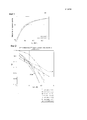
[15] Фиг. 1 - график, иллюстрирующий изменение кодовой скорости в соответствии с вариантом осуществления настоящего изобретения;[15] FIG. 1 is a graph illustrating a change in code rate in accordance with an embodiment of the present invention;
[16] Фиг. 2 и 3 - графики, иллюстрирующие эффективность LDPC-кода в соответствии с вариантом осуществления настоящего изобретения;[16] FIG. 2 and 3 are graphs illustrating the effectiveness of an LDPC code in accordance with an embodiment of the present invention;
[17] Фиг. 4 - график, иллюстрирующий изменение эффективной кодовой скорости в соответствии с вариантом осуществления настоящего изобретения;[17] FIG. 4 is a graph illustrating a change in effective code rate in accordance with an embodiment of the present invention;
[18] Фиг. 5 - график, иллюстрирующий эффективность LDPC-кода в соответствии с вариантом осуществления настоящего изобретения;[18] FIG. 5 is a graph illustrating the effectiveness of an LDPC code in accordance with an embodiment of the present invention;
[19] Фиг. 6 - блок-схема последовательности операций, иллюстрирующая процедуру для исключения битов четности на основе длины информационных битов в соответствии с вариантом осуществления настоящего изобретения;[19] FIG. 6 is a flowchart illustrating a procedure for eliminating parity bits based on information bit lengths in accordance with an embodiment of the present invention;
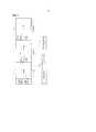
[20] Фиг. 7 - схема, иллюстрирующая структуру кадра для передачи двух типов битов четности в соответствии с вариантом осуществления настоящего изобретения;[20] FIG. 7 is a diagram illustrating a frame structure for transmitting two types of parity bits in accordance with an embodiment of the present invention;
[21] Фиг. 8 - схема, иллюстрирующая структуру LDPC-кода для поддержки передачи битов четности в соответствии с вариантом осуществления настоящего изобретения;[21] FIG. 8 is a diagram illustrating a structure of an LDPC code for supporting transmission of parity bits in accordance with an embodiment of the present invention;
[22] Фиг. 9 - график, иллюстрирующий изменение эффективной кодовой скорости в соответствии с вариантом осуществления настоящего изобретения;[22] FIG. 9 is a graph illustrating a change in effective code rate in accordance with an embodiment of the present invention;
[23] Фиг. 10 - блок-схема последовательности операций, иллюстрирующая процедуру для определения количества двух типов битов четности в соответствии с вариантом осуществления настоящего изобретения;[23] FIG. 10 is a flowchart illustrating a procedure for determining the number of two types of parity bits in accordance with an embodiment of the present invention;
[24] Фиг. 11 - блок-схема, иллюстрирующая сторону передачи в соответствии с вариантом осуществления настоящего изобретения; и[24] FIG. 11 is a block diagram illustrating a transmission side in accordance with an embodiment of the present invention; and
[25] Фиг. 12 - блок-схема, иллюстрирующая сторону приема в соответствии с вариантом осуществления настоящего изобретения.[25] FIG. 12 is a block diagram illustrating a receiving side according to an embodiment of the present invention.
Варианты осуществления изобретенияEmbodiments of the invention
[26] Далее будут подробно описаны различные варианты осуществления настоящего изобретения со ссылкой на прилагаемые чертежи. Общеизвестные функции и структуры не будут описываться, если они могут затруднить понимание сущности настоящего изобретения. Кроме того, используемые в этом документе термины определяются на основе функций в настоящем изобретении и могут меняться в соответствии с пользователями, намерением оператора или установившейся практикой. Поэтому определения терминов следует выполнять в зависимости от содержания по всему описанию изобретения.[26] Next, various embodiments of the present invention will be described in detail with reference to the accompanying drawings. Well-known functions and structures will not be described if they can complicate the understanding of the essence of the present invention. In addition, the terms used in this document are defined based on the functions in the present invention and may vary according to users, the intention of the operator, or established practice. Therefore, definitions of terms should be made depending on the content throughout the description of the invention.
[27] Хотя нижеследующее описание настоящего изобретения основывается на системе цифрового наземного видеовещания 2-го поколения (DVB-T2), которая является Европейским стандартом цифрового вещания, и системе цифрового видеовещания следующего поколения на переносные устройства (DVB-NGH), которая стандартизируется в настоящее время, настоящее изобретение в равной степени применяется к другим системам.[27] Although the following description of the present invention is based on a 2nd generation digital terrestrial video broadcasting system (DVB-T2), which is the European digital broadcasting standard, and a next generation portable digital video broadcasting system (DVB-NGH), which is being standardized in the present time, the present invention is equally applicable to other systems.
[28] Более того, хотя нижеследующее описание управляет кодовой скоростью, соответствующей передаче сигнальной информации, настоящее изобретение также применимо к передаче другой информации.[28] Moreover, although the following description controls the code rate corresponding to the transmission of signaling information, the present invention is also applicable to the transmission of other information.
[29] На стороне передачи вещательной системы/системы связи LDPC-кодер принимает Kldpc информационных битов LDPC, формирует Nparity битов четности и выводит Nldpc (=Kldpc+Nparity) кодированных битов LDPC. В нижеследующем описании для удобства будет описываться ввод и вывод "битов", но такое же описание также применяется к вводу и выводу символов.[29] On the transmission side of the broadcast / communication system, the LDPC encoder receives K ldpc LDPC information bits, generates N parity parity bits, and outputs N ldpc (= K ldpc + N parity ) LDPC encoded bits. In the following description, for convenience, input and output of “bits” will be described, but the same description also applies to input and output of characters.
[30] Когда в кодер вводятся сигнальные биты переменной длины, сторона передачи может выполнять сокращение и/или исключение (в дальнейшем называемое "сокращением/исключением"). А именно, если длина информационных битов LDPC в LDPC-кодере равна Kldpc, и сигнальные биты, имеющие длину битов Ksig, вводятся в LDPC-кодер, то сокращается (Kldpc-Ksig) битов. В этом документе сокращение означает заполнение (Kldpc-Ksig) "0"-ыми битами сигнальных битов для LDPC-кодирования, а после LDPC-кодирования - удаление заполненных "0"-ых битов, либо уменьшение размера матрицы контроля четности в LDPC-кодере, что обладает таким же эффектом, как сокращение на основе заполнения и удаления. Кроме того, исключение означает изъятие из передачи некоторых кодирующих битов, главным образом битов четности.[30] When variable-length signal bits are input to the encoder, the transmit side may perform reduction and / or exclusion (hereinafter referred to as “reduction / exclusion”). Namely, if the length of the LDPC information bits in the LDPC encoder is K ldpc , and the signal bits having the bit length K sig are input to the LDPC encoder, then the (K ldpc -K sig ) bits are reduced. In this document, the abbreviation means filling (K ldpc -K sig ) with “0” bits of the signal bits for LDPC encoding, and after LDPC encoding, deleting the filled “0” bits or decreasing the size of the parity check matrix in LDPC- an encoder that has the same effect as shrinking based on filling and deleting. In addition, an exception means the removal of certain coding bits, mainly parity bits, from transmission.
[31] Сторона передачи вещательной системы/системы связи может использовать два каскадных кодера. Например, кодер, который каскадирует код Боуза, Чоудхури, Хоквингема (BCH) с LDPC-кодом, то есть BCH/LDPC-кодер, принимает информационные биты BCH (информацию BCH или информационные биты), содержащие Kbch битов, и выводит кодированные биты BCH (или кодовое слово BCH, или кодированный BCH-блок), содержащие Nbch битов. Nbch равно количеству информационных битов LDPC, Kldpc и Nbch битов также могут называться информационными битами LDPC (или некодированным LDPC-блоком), которые являются информацией, введенной в LDPC-кодер. Кодированные биты BCH, то есть информационные биты LDPC, вводятся в LDPC-кодер и выводятся в виде кодированных битов LDPC, кодированного LDPC-блока или кодового слова LPDC, имеющего длину Nldpc.[31] The transmission side of a broadcast / communication system may use two cascade encoders. For example, an encoder that cascades a Bose, Chowdhury, Hawkingham (BCH) code with an LDPC code, that is, a BCH / LDPC encoder, receives BCH information bits (BCH information or information bits) containing K bch bits, and outputs encoded BCH bits (or a BCH codeword, or an encoded BCH block) containing N bch bits. N bch is equal to the number of LDPC information bits, K ldpc and N bch bits may also be referred to as LDPC information bits (or an uncoded LDPC block), which are information input to the LDPC encoder. The coded BCH bits, i.e., LDPC information bits, are input to an LDPC encoder and output as coded LDPC bits, an encoded LDPC block, or an LPDC codeword having a length of N ldpc .
[32] Когда информационное слово, которое включает в себя сигнальные биты, имеющие переменную длину, вводится в кодер, сторона передачи выполняет сокращение/исключение по отношению к кодовому слову, выведенному из кодера. То есть сигнальные биты, имеющие длину битов Ksig, вводятся в BCH/LDPC-кодер, и сокращается (Kbch-Ksig) битов. Как описано выше, сокращение означает, что (Kbch-Ksig) "0"-ых битов заполняются во входные сигнальные биты и кодируются по BCH/LDPC, а затем заполненные "0"-ые биты удаляются.[32] When an information word, which includes signal bits having a variable length, is input to the encoder, the transmit side performs a reduction / exclusion with respect to the code word output from the encoder. That is, signal bits having a bit length of K sig are input to a BCH / LDPC encoder, and (K bch -K sig ) bits are shortened. As described above, the abbreviation means that (K bch -K sig ) "0" bits are filled into the input signal bits and encoded by BCH / LDPC, and then the filled "0" bits are deleted.
[33] Как описано выше, сокращение уменьшает кодовую скорость, так что когда увеличивается количество битов, которые необходимо сократить (то есть длина битов сокращения), эффективность кодирования повышается. Однако, когда кодируется сигнальная информация, предпочтительно, чтобы эффективность кодирования не менялась с длиной входной информации. То есть, когда мощность приема в приемнике постоянна, предпочтительно, чтобы эффективность не варьировалась с длиной входного информационного слова. Поэтому с помощью регулирования количества битов, которые необходимо исключить (то есть длины битов исключения) в соответствии с количеством битов, которые необходимо сократить, обеспечивается устойчивая эффективность кодирования. Количество битов, которые необходимо исключить, определяется в соответствии с длиной битов входного информационного слова, то есть количеством битов входного информационного слова, так что количество битов, которые необходимо исключить, зависит от количества битов входного информационного слова.[33] As described above, the reduction reduces the code rate, so that when the number of bits to be reduced is increased (that is, the length of the reduction bits), the encoding efficiency is increased. However, when signaling information is encoded, it is preferable that the encoding efficiency does not change with the length of the input information. That is, when the receiver power is constant, it is preferable that the efficiency does not vary with the length of the input information word. Therefore, by adjusting the number of bits to be excluded (i.e., the length of the exception bits) in accordance with the number of bits to be reduced, a stable coding efficiency is provided. The number of bits to be excluded is determined according to the bit length of the input information word, that is, the number of bits of the input information word, so the number of bits to be excluded depends on the number of bits of the input information word.
[34] Ниже будут описываться варианты осуществления для определения входного параметра, используемого для исключения, то есть количества битов Npunc, которые следует исключить.[34] Embodiments for determining an input parameter used for exclusion, that is, the number of N punc bits to be excluded, will be described below.
[35] В одном варианте осуществления Npunc может вычисляться с использованием одного из Уравнений с (1) по (4).[35] In one embodiment, the N punc can be calculated using one of Equations (1) through (4).
[36] Уравнение (1) используется, когда каскадируется BCH-код, а Уравнение (2) используется, когда BCH-код не каскадируется. То есть, когда BCH-код каскадируется, количество битов, которые следует сократить, равно (Kbch-Ksig), так что Npunc может вычисляться с использованием Уравнения (1).[36] Equation (1) is used when the BCH code is cascaded, and Equation (2) is used when the BCH code is not cascaded. That is, when the BCH code is cascaded, the number of bits to be reduced is (K bch -K sig ), so the N punc can be calculated using Equation (1).
[37] ![]()
![]()
[38] … (1)[38] ... (1)
[39] Когда BCH-код не каскадируется, количество битов, которые следует сократить, равно (Kldpc-Ksig), так что Npunc может вычисляться с использованием Уравнения (2).[39] When the BCH code is not cascaded, the number of bits to be reduced is (K ldpc -K sig ), so that N punc can be calculated using Equation (2).
[40] ![]()
![]()
[41] … (2)[41] ... (2)
[42] В Уравнениях (1) и (2) A указывает отношение количества битов, которые следует сократить, к количеству битов, которые необходимо исключить, а (Kbch-Ksig) и (Kldpc-Ksig) указывают количество битов, которые следует сократить. Kbch указывает количество информационных битов BCH (то есть длину информационных битов), введенных для формирования кодированных битов BCH, включающих в себя Kldpc битов, посредством BCH-кодирования. Kldpc указывает количество информационных битов LDPC, введенных для формирования кодированных битов LDPC. Ksig указывает длину битов информационного слова, введенного в кодер, перед сокращением. B указывает поправочный коэффициент. Операция ![]()
![]()
[43] Когда количество битов, которые необходимо исключить, вычисляется на основе Уравнений (1) или (2), можно получить кодовую скорость меньше, чем когда сокращение и исключение не выполняются. В вышеприведенном описании, если B равен 0, то его можно опустить.[43] When the number of bits to be excluded is calculated based on Equations (1) or (2), it is possible to obtain a code rate less than when the reduction and exclusion are not performed. In the above description, if B is 0, then it can be omitted.
[44] В качестве альтернативы, когда Npunc вычисляется с использованием Уравнений (3) или (4), можно получить кодовую скорость меньше, чем когда сокращение и исключение не выполняются.[44] Alternatively, when N punc is calculated using Equations (3) or (4), it is possible to obtain a code rate less than when reduction and exclusion are not performed.
[45] Точнее говоря, когда BCH-код каскадируется, количество битов, которые следует сократить, равно (Kbch-Ksig), так что Npunc может вычисляться с использованием Уравнения (3).[45] More specifically, when the BCH code is cascaded, the number of bits to be reduced is (K bch -K sig ), so that N punc can be calculated using Equation (3).
[46] ![]()
![]()
[47] ![]()
![]()
[48] Когда BCH-код не каскадируется, количество битов, которые следует сократить, равно (Kldpc-Ksig), так что Npunc может вычисляться с использованием Уравнения (4).[48] When the BCH code is not cascaded, the number of bits to be reduced is (K ldpc -K sig ), so that N punc can be calculated using Equation (4).
[49] ![]()
![]()
[50] ![]()
![]()
[51] В Уравнениях (3) и (4) A указывает отношение количества битов, которые необходимо сократить, к количеству битов, которые необходимо исключить, а (Kbch-Ksig) и (Kldpc-Ksig) указывают количество битов, которые необходимо сократить. Kbch указывает количество информационных битов BCH (то есть длину информационных битов), введенных для формирования кодированных битов BCH, состоящих из Kldpc битов, посредством BCH-кодирования. Kldpc указывает количество информационных битов LDPC, введенных для формирования кодированных битов LDPC. Ksig указывает длину битов информационного слова, введенного в кодер, перед сокращением. B указывает поправочный коэффициент. Ksig_min указывает длину битов самого короткого информационного слова среди информационных слов, которые можно ввести в кодер.[51] In Equations (3) and (4), A indicates the ratio of the number of bits to be reduced to the number of bits to be excluded, and (K bch -K sig ) and (K ldpc -K sig ) indicate the number of bits, which need to be reduced. K bch indicates the number of BCH information bits (i.e., the length of information bits) input to generate BCH coded bits consisting of K ldpc bits by BCH coding. K ldpc indicates the number of LDPC information bits introduced to form the encoded LDPC bits. K sig indicates the bit length of the information word input to the encoder before abbreviation. B indicates the correction factor. K sig_min indicates the bit length of the shortest information word among the information words that can be entered into the encoder.
[52] В Уравнениях (3) и (4) Npunc меньше количества битов четности, Nparity, только когда выполняется условие B<Nparity-A(Kldpc-Ksig_min).[52] In Equations (3) and (4), the N punc is less than the number of parity bits, N parity , only when the condition B <N parity -A (K ldpc -K sig_min ) is satisfied .
[53] В Уравнениях с (1) по (4) Npunc может изменяться в соответствии с параметрами A и B. Соответственно, кодовая скорость может изменяться в соответствии с A и B. Когда вводится Kldpc битов и выводится Nldpc кодированных битов, кодовая скорость LDPC-кода, R, может вычисляться с использованием Уравнения (5).[53] In Equations (1) through (4), the N punc may vary in accordance with parameters A and B. Accordingly, the code rate may vary in accordance with A and B. When K ldpc bits are input and N ldpc encoded bits are output, the code rate of the LDPC code, R, can be calculated using Equation (5).
[54] 
[55] Для Ksig битов входного информационного слова эффективная кодовая скорость Reff после сокращения и исключения вычисляется с использованием Уравнения (6).[55] For the K sig bits of the input information word, the effective code rate R eff after reduction and exclusion is calculated using Equation (6).
[56] 
[57] В Уравнении (6) Nbch_parity указывает количество битов четности BCH-кода, которое равно 0, когда BCH-код не используется.[57] In Equation (6), N bch_parity indicates the number of parity bits of the BCH code, which is 0 when the BCH code is not used.
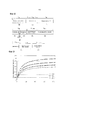
[58] Фиг. 1 - график, иллюстрирующий изменение эффективной кодовой скорости в соответствии с вариантом осуществления настоящего изобретения. В частности, фиг. 1 иллюстрирует изменение кодовой скорости для Kbch=2100, Kldpc=2160 и Nldpc=8640, когда A=1,35 и B=3320 применяются в Уравнении (3), и когда A=1,32 и B=3320 применяются в Уравнении (3). Как показано, кодовая скорость для передачи информации меняется вместе с A, то есть когда A увеличивается, кодовая скорость также увеличивается.[58] FIG. 1 is a graph illustrating a change in effective code rate in accordance with an embodiment of the present invention. In particular, FIG. 1 illustrates a code rate change for K bch = 2100, K ldpc = 2160 and N ldpc = 8640, when A = 1.35 and B = 3320 are applied in Equation (3), and when A = 1.32 and B = 3320 are applied in Equation (3). As shown, the code rate for transmitting information changes with A, that is, when A increases, the code rate also increases.
[59] Фиг. 2 иллюстрирует частоту появления ошибочных кадров (FER) кодового слова относительно различных длин информационных битов: 280, 396, 880, 1350, 1550, 1670 и 1900 для A=1,35 и B=3320.[59] FIG. 2 illustrates the frequency of occurrence of error frames (FER) of a codeword with respect to different information bit lengths: 280, 396, 880, 1350, 1550, 1670 and 1900 for A = 1.35 and B = 3320.
[60] Ссылаясь на фиг. 2, когда количество входных информационных битов, Ksig, равно 280, возникает снижение эффективности. Поэтому для FER=10e-4 разница эффективности между наилучшей эффективностью и наихудшей эффективностью составляет 0,7 дБ.[60] Referring to FIG. 2, when the number of input information bits, K sig , is 280, a decrease in efficiency occurs. Therefore, for FER = 10e-4, the difference in efficiency between the best efficiency and the worst efficiency is 0.7 dB.
[61] Фиг. 3 иллюстрирует FER кодового слова относительно различных длин информационных битов: 280, 396, 880, 1350, 1550, 1670, 1900 для A=1,32 и B=3320.[61] FIG. 3 illustrates the FER of a codeword with respect to different information bit lengths: 280, 396, 880, 1350, 1550, 1670, 1900 for A = 1.32 and B = 3320.
[62] Ссылаясь на фиг. 3, кодовая скорость меньше таковой на фиг. 2, так что достигается повышение общей эффективности. В частности, когда количество входных информационных битов, Ksig, равно 1350, эффективность гораздо лучше, чем в других случаях. Также видно, что для FER=10e-4 разница эффективности между наилучшей эффективностью и наихудшей эффективностью составляет 0,7 дБ.[62] Referring to FIG. 3, the code rate is less than that in FIG. 2, so that an increase in overall efficiency is achieved. In particular, when the number of input information bits, K sig , is 1350, the efficiency is much better than in other cases. It is also seen that for FER = 10e-4, the difference in efficiency between the best efficiency and the worst efficiency is 0.7 dB.
[63] Как описано выше, предпочтительно, чтобы эффективность кодирования не сильно варьировалась с длиной входных информационных битов. Таким образом, необходим способ для регулирования A и B в Уравнениях с (1) по (4) в соответствии с длиной входных информационных битов.[63] As described above, it is preferable that the coding efficiency does not vary greatly with the length of the input information bits. Thus, a method is needed to control A and B in Equations (1) through (4) in accordance with the length of the input information bits.
[64] Поэтому в соответствии с вариантом осуществления настоящего изобретения Npunc определяется с использованием Уравнений (7) и (8).[64] Therefore, in accordance with an embodiment of the present invention, N punc is determined using Equations (7) and (8).
[65] 
[66] 
[67] В Уравнениях (7) и (8) разные значения A и B, то есть A1 и B1 или A2 и B2, используются в соответствии с длиной входных информационных битов.[67] In Equations (7) and (8), different values of A and B, that is, A 1 and B 1 or A 2 and B 2 , are used in accordance with the length of the input information bits.
[68] Если B1 является целым числом, то Уравнение (7) можно привести к следующему Уравнению (7a).[68] If B 1 is an integer, then Equation (7) can be reduced to the following Equation (7a).
[69] 
[70] Если A1=C+D (где C - целое число, а D - вещественное число), то Уравнение (7) можно привести к следующему Уравнению (7b).[70] If A 1 = C + D (where C is an integer and D is a real number), then Equation (7) can be reduced to the following Equation (7b).
[71] 
[72] 
[73] Также Уравнение (8) можно изменить аналогично Уравнениям (7a) и (7b).[73] Equation (8) can also be changed similarly to Equations (7a) and (7b).
[74] В Уравнениях (7) и (8) разделяется случай длины входных информационных битов меньше заранее установленного порогового значения Kth и случай длины входных информационных битов больше порогового значения Kth. Однако для разделения случая длины входных информационных битов может использоваться множество пороговых значений, так что могут использоваться две или более пары A и B.[74] In Equations (7) and (8), the case of the length of the input information bits is less than the predetermined threshold value K th and the case of the length of the input information bits is greater than the threshold value K th is separated . However, a plurality of threshold values may be used to separate the length case of the input information bits, so that two or more pairs A and B can be used.
[75] Kth можно определить опытным путем, чтобы не вызывать разницы в эффективности кодирования с Npunc. В частности, значение, соответствующее случаю, где эффективность относительно хорошая, или случаю, где эффективность относительно плохая, определяется как Kth. К тому же разные пары параметров (A1, B1) и (A2, B2) определяются так, что для Ksig=Kth значения Npunc равны друг другу.[75] K th can be determined empirically so as not to cause differences in coding efficiency with N punc . In particular, the value corresponding to the case where the efficiency is relatively good, or the case where the efficiency is relatively poor, is defined as K th . Moreover, different pairs of parameters (A 1 , B 1 ) and (A 2 , B 2 ) are determined so that for K sig = K th the values of N punc are equal to each other.
[76] Как описано выше, количество битов, которые необходимо исключить, предпочтительно регулируется в соответствии с количеством битов, которые необходимо сократить, и количество битов, которые необходимо сократить, определяется в соответствии с длиной битов входного информационного слова. Таким образом, A1 и A2, указывающие отношения количества битов, которые необходимо сократить, к количеству битов, которые необходимо исключить, могут быть постоянными значениями, определенными в соответствии с длиной битов входного информационного слова. Поэтому B1 и B2 могут определяться как постоянные значения.[76] As described above, the number of bits to be eliminated is preferably adjusted in accordance with the number of bits to be reduced, and the number of bits to be reduced is determined in accordance with the bit length of the input information word. Thus, A 1 and A 2 indicating the ratio of the number of bits to be reduced to the number of bits to be excluded can be constant values determined in accordance with the bit length of the input information word. Therefore, B 1 and B 2 can be defined as constant values.
[77] Как только Npunc определяется, как описано выше, сторона передачи исключает биты четности из кодированных битов, сформированных путем кодирования входных информационных битов, с помощью Npunc.[77] Once the N punc is determined as described above, the transmission side excludes the parity bits from the encoded bits generated by encoding the input information bits using the N punc .
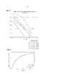
[78] Фиг. 4 - график, иллюстрирующий изменение эффективной кодовой скорости в соответствии с вариантом осуществления настоящего изобретения, где A=1,35 и B=3320 в Уравнении (3), и A=1,32 и B=3320 в Уравнении (3) сравниваются с использованием Уравнений (7) и (8), что помечается как "Предложено".[78] FIG. 4 is a graph illustrating a change in effective code rate in accordance with an embodiment of the present invention, where A = 1.35 and B = 3320 in Equation (3), and A = 1.32 and B = 3320 in Equation (3) are compared with using Equations (7) and (8), which is marked as “Proposed”.
[79] В частности, "Предложено" указывает, что Kbch=2100, Kldpc=2160, Nldpc=8640, A1=1,3, B1=3357, A2=1,35, B2=3320 и Kth=1350 применяются в Уравнении (7). Как проиллюстрировано на фиг. 4, когда Ksig больше 1350, что равно Kth, "Предложенный" случай показывает такую же кодовую скорость, как и при A=1,35 и B=3320 в Уравнении (3).[79] In particular, “Proposed” indicates that K bch = 2100, K ldpc = 2160, N ldpc = 8640, A 1 = 1.3, B 1 = 3357, A 2 = 1.35, B 2 = 3320 and K th = 1350 are applied in Equation (7). As illustrated in FIG. 4, when K sig is greater than 1350, which is equal to K th , the “Proposed” case shows the same code rate as with A = 1.35 and B = 3320 in Equation (3).
[80] Фиг. 5 - график, иллюстрирующий FER в соответствии с вариантом осуществления настоящего изобретения. В частности, фиг. 5 иллюстрирует характеристику FER относительно различных длин информационных битов: 280, 396, 880, 1350, 1550, 1670 и 1900.[80] FIG. 5 is a graph illustrating an FER in accordance with an embodiment of the present invention. In particular, FIG. 5 illustrates the FER characteristic with respect to different information bit lengths: 280, 396, 880, 1350, 1550, 1670, and 1900.
[81] Ссылаясь на фиг. 5, для длины входных информационных битов в 280 кодовая скорость меньше проиллюстрированной на фиг. 2, так что эффективность лучше. Для длины входных информационных битов в 1350 кодовая скорость больше проиллюстрированной на фиг. 3, так что возникает снижение эффективности. Поэтому разница общей эффективности составляет 0,3 дБ, и разница эффективности кодирования уменьшается по сравнению с фиг. 2 и 3.[81] Referring to FIG. 5, for an input information bit length of 280, the code rate is less than that illustrated in FIG. 2, so the efficiency is better. For an input information bit length of 1350, the code rate is greater than that illustrated in FIG. 3, so that a decrease in efficiency occurs. Therefore, the difference in overall efficiency is 0.3 dB, and the difference in coding efficiency is reduced compared to FIG. 2 and 3.
[82] В вышеприведенном описании количество битов Npunc, которые необходимо исключить, вычисляется с использованием вышеупомянутых уравнений. Однако в нижеследующем описании значение, полученное с использованием вышеупомянутых уравнений, предполагается промежуточным значением Npunc, то есть промежуточным количеством битов Npunc_temp, которые необходимо исключить, и посредством нескольких процессов Npunc получается точнее.[82] In the above description, the number of N punc bits to be excluded is calculated using the above equations. However, in the following description, the value obtained using the above equations is assumed to be an intermediate value of N punc , that is, an intermediate number of N punc_temp bits that need to be excluded, and through several processes N punc is obtained more precisely.
[83] В соответствии с вариантом осуществления настоящего изобретения сторона передачи при выполнении исключения с использованием Npunc может точнее регулировать Npunc в соответствии с дополнительными параметрами, например количеством битов четности BCH, порядком модуляции и т. п. Ниже будет описываться процедура для вычисления окончательного количества битов, которые необходимо исключить, с использованием Npunc_temp.[83] According to an embodiment of the present invention, the transmitting side, when executing an exception using N punc, can more accurately adjust the N punc according to additional parameters, for example, the number of BCH parity bits, modulation order, etc. The procedure for calculating the final will be described below. the number of bits to be excluded using N punc_temp .
[84] Этап 1:[84] Stage 1:
[85] Промежуточное количество битов Npunc_temp, которые необходимо исключить, вычисляется с использованием Уравнения (9), которое практически такое же, как вышеописанное Уравнение (7) и связанное с ним описание.[85] The intermediate number of N punc_temp bits to be excluded is calculated using Equation (9), which is substantially the same as the above Equation (7) and the associated description.
[86] 
[87] Используется LDPC-код, каскадированный с BCH-кодом, и в Уравнении (9) используются значения (A1, B1)=(1,3, 3357) и (A2, B2)=(1,35, 3320) из фиг. 4.[87] An LDPC code cascaded with a BCH code is used, and in Equation (9), the values (A 1 , B 1 ) = (1,3, 3357) and (A 2 , B 2 ) = (1.35) are used , 3320) of FIG. four.
[88] Этап 2:[88] Stage 2:
[89] Промежуточное количество битов Npost_temp, которые необходимо кодировать, вычисляется с использованием Npunc_temp, как показано в Уравнении (10).[89] The intermediate number of N post_temp bits to be encoded is calculated using N punc_temp , as shown in Equation (10).
[90] ![]()
![]()
[91] В Уравнении (10) Ksig указывает количество входных информационных битов, как описано выше, и может указывать, например, количество битов сигнальной информации. Nbch_parity указывает количество битов четности BCH, а Nldpc_parity_ext_4K указывает постоянное значение, определенное в соответствии с типом LDPC-кода.[91] In Equation (10), K sig indicates the number of input information bits, as described above, and may indicate, for example, the number of bits of signal information. N bch_parity indicates the number of BCH parity bits, and N ldpc_parity_ext_4K indicates a constant value determined in accordance with the type of LDPC code.
[92] Этап 3:[92] Stage 3:
[93] Принимая во внимание Npost_temp и порядок модуляции, окончательное количество битов, которые необходимо кодировать (количество битов каждого LDPC-блока), вычисляется с использованием Уравнения (11a):[93] Given the N post_temp and the modulation order, the final number of bits to be encoded (the number of bits of each LDPC block) is calculated using Equation (11a):
[94] 
[95] В Уравнении (11a) ηMOD указывает порядок модуляции, который равен 1, 2, 4 и 6 для двухпозиционной фазовой манипуляции (BPSK), квадратурной PSK (QPSK), 16-позиционной квадратурной амплитудной модуляции (16-QAM) и 64-позиционной QAM (64-QAM) соответственно.[95] In Equation (11a), η MOD indicates a modulation order that is 1, 2, 4, and 6 for on-off phase shift keying (BPSK), quadrature PSK (QPSK), 16-position quadrature amplitude modulation (16-QAM), and 64 positional QAM (64-QAM), respectively.
[96] Определение количества кодированных битов каждого блока информационного слова, Npost, как показано в Уравнении (11a), заставляет Npost быть величиной, кратной количеству столбцов в блочном перемежителе. Блочный перемежитель, хотя не показан и дополнительно не описан, используется, когда биты каждого LDPC-блока позже перемежаются побитово.[96] Determining the number of encoded bits of each block of the information word, N post , as shown in Equation (11a), causes N post to be a multiple of the number of columns in the block interleaver. Block interleaver, although not shown and not further described, is used when the bits of each LDPC block are later bitwise interleaved.
[97] Когда блочный перемежитель не используется, например, когда используются только BPSK и QPSK, Уравнение (11a) можно преобразовать в Уравнение (11b).[97] When the block interleaver is not used, for example, when only BPSK and QPSK are used, Equation (11a) can be converted to Equation (11b).
[98] 
[99] Этап 4:[99] Step 4:
[100] Количество битов Npunc, которые необходимо исключить из битов четности каждого LDPC-блока, вычисляется с использованием Уравнения (12).[100] The number of N punc bits to be excluded from the parity bits of each LDPC block is calculated using Equation (12).
[101] Npunc = Npunc_temp - (Npost - Npost_temp) …(12)[101] N punc = N punc_temp - (N post - N post_temp ) ... (12)
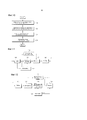
[102] Фиг. 6 - блок-схема последовательности операций, иллюстрирующая процедуру для исключения битов четности на основе длины входных информационных битов в соответствии с вариантом осуществления настоящего изобретения.[102] FIG. 6 is a flowchart illustrating a procedure for eliminating parity bits based on the length of input information bits in accordance with an embodiment of the present invention.
[103] Ссылаясь на фиг. 6, на этапе 600 определяется количество входных информационных битов, включая сигнальную информацию для передачи (то есть длина входных информационных битов). На этапе 602 сторона передачи проверяет параметры для вычисления количества битов, которые необходимо исключить, то есть длины битов исключения. А именно, сторона передачи определяет, выбрать ли (A1, B1) или (A2, B2), в соответствии с длиной входных информационных битов, используя Уравнения (7) и (8). Хотя и не показано, одна из двух или более заранее установленных пар параметров может выбираться в соответствии с длиной входных информационных битов. В качестве альтернативы на этапе 602 сторона передачи может получить значения параметров (A1, B1)=(1,3, 3357) или (A2, B2)=(1,35, 3320), которые необходимо использовать в Уравнении (9), в соответствии с результатом сравнения длины входных информационных битов с заранее установленным пороговым значением, равным 1350.[103] Referring to FIG. 6, in
[104] На этапе 604 количество битов четности, которые необходимо исключить (то есть длина битов четности к исключению), вычисляется на основе определенных параметров, например, используя Уравнения 7 и 8 или Уравнения с (9) по (12). На этапе 606 биты четности кодового слова исключаются на основе вычисленной длины битов четности к исключению.[104] At
[105] Биты четности, сформированные по отношению к сигнальным битам, которые являются входными информационными битами, могут передаваться распределенным образом посредством того же кадра, что и кадр, в котором передаются сигнальные биты, и предыдущего кадра. Биты четности, переданные посредством того же кадра, что и кадр, который переносит сигнальные биты, в этом документе будут называться первой четностью, а биты четности, переданные посредством предыдущего кадра, в этом документе будут называться второй четностью или дополнительной четностью.[105] Parity bits generated with respect to the signal bits, which are input information bits, may be transmitted in a distributed manner by the same frame as the frame in which the signal bits are transmitted and the previous frame. Parity bits transmitted by the same frame as the frame that carries the signal bits in this document will be called first parity, and parity bits transmitted by the previous frame in this document will be called second parity or additional parity.
[106] Фиг. 7 - схема, которая иллюстрирует структуру кадра для передачи двух типов битов четности в соответствии с вариантом осуществления настоящего изобретения.[106] FIG. 7 is a diagram that illustrates a frame structure for transmitting two types of parity bits in accordance with an embodiment of the present invention.
[107] Ссылаясь на фиг. 7, сигнальные биты Уровня-1 передаются посредством i-го кадра 702; первая четность 710, сформированная для сигнальных битов, передается посредством i-го кадра 702 вместе с сигнальными битами; и дополнительная четность 712 передается посредством (i-1)-го кадра 700.[107] Referring to FIG. 7, the Level-1 signaling bits are transmitted by the
[108] В соответствии с вариантом осуществления настоящего изобретения сторона приема выполняет декодирование на основе сигнальных битов и первой четности 710, принятой посредством i-го кадра 702. Если декодирование терпит неудачу, то сторона приема также выполняет декодирование с использованием дополнительной четности 712, принятой посредством (i-1)-го кадра 700.[108] According to an embodiment of the present invention, the receiving side performs decoding based on the signal bits and the
[109] В соответствии с другим вариантом осуществления настоящего изобретения, если декодирование относительно сигнальных битов и первой четности 710 терпит неудачу, то сторона приема определяет, что декодирование относительно сигнальных битов терпит неудачу, сохраняет дополнительную четность, включенную в i-ый кадр 702, а затем принимает (i+1)-ый кадр.[109] According to another embodiment of the present invention, if decoding with respect to signal bits and
[110] В соответствии с еще одним вариантом осуществления настоящего изобретения сторона приема всегда сохраняет дополнительную четность 712, принятую посредством (i-1)-го кадра 700, и выполняет декодирование на основе сигнальных битов и первой четности 710, принятой посредством i-го кадра 702, и сохраненной дополнительной четности 712.[110] According to another embodiment of the present invention, the receiving side always stores the
[111] Ниже будет подробнее описываться способ для определения количества битов дополнительной четности.[111] A method for determining the number of bits of additional parity will be described in more detail below.
[112] В соответствии с вариантом осуществления настоящего изобретения количество битов дополнительной четности может выражаться с использованием Уравнения (13).[112] According to an embodiment of the present invention, the number of bits of additional parity may be expressed using Equation (13).
[113] ![]()
![]()
[114] В Уравнении (13) α·Il указывает отношение количества битов первой четности к количеству битов дополнительной четности, где α может быть постоянным значением, Ii может выбираться между 0 и L-1, и L1 указывает отношение дополнительной четности L1. Ii может передаваться посредством отдельной сигнализации "L1_AP_RATIO". Когда Ii=0, биты дополнительной четности не используются. Ntx_parity указывает количество битов четности, переданных посредством того же кадра, что и кадр для информационного слова (то есть битов первой четности), и также может означать количество битов четности, которые необходимо фактически передать. В этом случае Ntx_parity может вычисляться в виде Nparity - Npunc.[114] In Equation (13), α · I l indicates the ratio of the number of bits of the first parity to the number of bits of additional parity, where α can be a constant value, I i can be selected between 0 and L-1, and L1 indicates the ratio of additional parity L1. I i can be transmitted via a separate signaling "L1_AP_RATIO". When I i = 0, bits of additional parity are not used. N tx_parity indicates the number of parity bits transmitted by the same frame as the frame for the information word (i.e., first parity bits), and may also indicate the number of parity bits to actually be transmitted. In this case, N tx_parity can be calculated as N parity - N punc .
[115] Фиг. 8 - схема, иллюстрирующая LDPC-код для поддержки передачи четности в соответствии с вариантом осуществления настоящего изобретения.[115] FIG. 8 is a diagram illustrating an LDPC code for supporting parity transmission in accordance with an embodiment of the present invention.
[116] Ссылаясь на фиг. 8, кодовое слово LPDC включает в себя Kldpc информационных битов 800 LDPC, Nparity битов 802 четности и MIR битов 804 четности с нарастающей избыточностью (IR). Для удобства Nparity битов 802 четности и MIR битов 804 четности с IR в этом документе вместе называются битами четности. Структура LDPC-кода, проиллюстрированная на фиг. 8, разрабатывается с учетом битов 802 четности. Поэтому при исключении биты 804 четности с IR исключаются. LDPC-код из фиг. 8 может быть выражен в виде битов четности без установления различий между битами 802 четности и битами 804 четности с IR.[116] Referring to FIG. 8, the LPDC codeword includes K ldpc information bits 800 LDPC, N parity parity bits 802 and M IR parity bits 804 with increasing redundancy (IR). For convenience, the N parity parity bits 802 and the M IR parity bits 804 with IR are collectively referred to as parity bits in this document. The LDPC code structure illustrated in FIG. 8 is being designed with
[117] Чтобы кодировать сигнальные биты 806, информационные биты 800 LDPC могут включать в себя сигнальные биты 806, биты 807 четности для BCH-кода и "0"-ые заполняющие биты 808 для сокращения. Биты 802 четности и биты 804 четности с IR включают в себя неисключенные биты 810 четности и исключенные биты 812 четности. В этом документе точное положение (то есть индекс) каждого бита не является существенным для предмета настоящего изобретения, а именно, какие биты между битами 802 четности и битами 804 четности с IR нужно исключать, а какие биты между ними исключать не нужно. Соответственно, конкретный шаблон исключения в этом документе описываться не будет.[117] To encode the
[118] Биты 807 четности BCH-кода существуют, когда используется каскадный код из BCH-кода и LDPC-кода, и биты 807 четности BCH будут отброшены, когда используется только LDPC-код.[118]
[119] Сигнальные биты 806, биты 807 четности BCH и неисключенные биты 810 четности образуют первую часть 814, которая передается позже посредством i-го кадра 702, как проиллюстрировано на фиг. 7. Некоторые из исключенных битов 812 четности образуют дополнительную четность 816, которая передается позже посредством (i-1)-го кадра 700, как проиллюстрировано на фиг. 7. То есть некоторые из исключенных битов 812 четности являются тем же самым, что и дополнительные четности 807 и 712.[119] The
[120] Дополнительная четность 708 может определяться разными способами. Например, исключенные биты 812 четности предпочтительно могут выбираться в качестве дополнительной четности.[120]
[121] Для Kbch=2100, Kldpc=2160, Nldpc=4320 и MIR=4320, Rldpc=Kldpc/Nldpc=1/2 и RIR=Kldpc/(Nldpc+Mldpc)=1/4. В этом случае в соответствии с вариантом осуществления настоящего изобретения Npunc может вычисляться на основе Уравнения 7 с использованием Уравнения (14) ниже.[121] For K bch = 2100, K ldpc = 2160, N ldpc = 4320 and M IR = 4320, R ldpc = K ldpc / N ldpc = 1/2 and R IR = K ldpc / (N ldpc + M ldpc ) = 1/4. In this case, in accordance with an embodiment of the present invention, N punc can be calculated based on Equation 7 using Equation (14) below.
[122] 
[123] В Уравнении (14) A1=1,3, B1=3357, A2=1,35, B2=3320 и Kth=1350. Поэтому из битов 802 четности и битов 804 четности с IR исключается Npunc битов четности на основе Уравнения (14).[123] In Equation (14), A 1 = 1.3, B 1 = 3357, A 2 = 1.35, B 2 = 3320, and K th = 1350. Therefore, N punc parity bits based on Equation (14) are excluded from the
[124] В соответствии с другим вариантом осуществления настоящего изобретения можно исключить Npunc битов четности, полученных на основе Npunc_temp в Уравнении (9) с использованием Уравнений с (10) по (12).[124] According to another embodiment of the present invention, N punc parity bits obtained based on the N punc_temp in Equation (9) can be excluded using Equations (10) through (12).
[125] Точные значения параметров, используемые для вычисления Npunc, можно определить в соответствии со схемой модуляции, используемой для передачи, и количеством символов мультиплексирования с ортогональным частотным разделением каналов (OFDM). Например, когда 2n-квадратурная амплитудная модуляция (QAM) используется в качестве схемы модуляции, количество битов (Ksig+Nbch_parity+Nparity+MIR-Npunc), которые необходимо передавать, является величиной, кратной n. В этом документе Ksig указывает количество входных битов сигнальной информации, Nbch_parity указывает количество битов четности BCH-кода, а n указывает порядок схемы модуляции.[125] The exact parameter values used to calculate the N punc can be determined in accordance with the modulation scheme used for transmission and the number of orthogonal frequency division multiplexing (OFDM) symbols. For example, when 2 n- quadrature amplitude modulation (QAM) is used as a modulation scheme, the number of bits (K sig + N bch_parity + N parity + M IR -N punc ) that must be transmitted is a multiple of n. In this document, K sig indicates the number of input bits of the signal information, N bch_parity indicates the number of parity bits of the BCH code, and n indicates the order of the modulation scheme.
[126] Количество битов дополнительной четности 712 из фиг. 7 или дополнительной четности 816 из фиг. 8 может вычисляться с использованием Уравнения (15).[126] The number of bits of
[127] 
[128] В Уравнении (15) I0=0, I1=1, I2=2 и I3=3. Кроме того, α=0,35 применяется в Уравнении (13), где α является значением, выбранным, чтобы удовлетворять Уравнению (16) ниже.[128] In Equation (15), I 0 = 0, I 1 = 1, I 2 = 2, and I 3 = 3. In addition, α = 0.35 is used in Equation (13), where α is a value selected to satisfy Equation (16) below.
[129] ![]()
![]()
[130] …(16)[130] ... (16)
[131] То есть α определяется как максимальное значение среди значений, в которых сумма количества битов первой четности, Ntx_parity, и количества битов дополнительной четности, Nadd_parity, которые передаются, когда Il является максимальным значением IL-1 и Ksig является максимальной длиной среди входных информационных битов, Ksig_max, то есть (Ntx_parity + Nadd_parity), является максимальной, и эта сумма меньше (Nparity + MIR).[131] That is, α is defined as the maximum value among the values in which the sum of the number of bits of the first parity, N tx_parity , and the number of bits of additional parity, N add_parity , which are transmitted when I l is the maximum value of I L-1 and K sig is the maximum length among the input information bits, K sig_max , that is (N tx_parity + N add_parity ), is the maximum, and this amount is less (N parity + M IR ).
[132] Когда максимальная длина среди входных информационных битов, Ksig_max, равна 2100, Npunc=3320, так что Ntx_parity=3160, а когда Il является максимальным значением IL-1=I3=3, Nadd_parity=0,35×3×3160 = 3318, так что Ntx_parity + Nadd_parity=6478, что меньше Nparity + MIR=6480.[132] When the maximum length among the input information bits, K sig_max , is 2100, N punc = 3320, so N tx_parity = 3160, and when I l is the maximum value I L-1 = I 3 = 3, N add_parity = 0 , 35 × 3 × 3160 = 3318, so N tx_parity + N add_parity = 6478, which is less than N parity + M IR = 6480.
[133] Ниже будет описываться вариант осуществления для получения более точного Nadd_parity с учетом схемы модуляции, используемой для передачи на основе Nadd_parity, полученной посредством вышеупомянутых уравнений.[133] An embodiment will be described below to obtain a more accurate N add_parity taking into account the modulation scheme used for transmission based on N add_parity obtained by the above equations.
[134] Уравнение (16) предполагает, что используется схема модуляции BPSK. То есть α определяется так, что количество битов первой четности и количество битов дополнительной четности, переданных при использовании схемы модуляции BPSK, меньше Nparity+MIR. Поэтому, когда используется другая схема модуляции, например QPSK, 16-QAM или 64-QAM, необходима поправка относительно Nadd_parity, чтобы количество битов первой четности и количество битов дополнительной четности было меньше Nparity + MIR. Поэтому количество промежуточных битов дополнительной четности можно получить с использованием Уравнения (17).[134] Equation (16) assumes that a BPSK modulation scheme is used. That is, α is determined so that the number of first parity bits and the number of additional parity bits transmitted using the BPSK modulation scheme is less than N parity + M IR . Therefore, when another modulation scheme is used, for example QPSK, 16-QAM or 64-QAM, a correction is required for N add_parity so that the number of bits of the first parity and the number of bits of additional parity are less than N parity + M IR . Therefore, the number of intermediate bits of additional parity can be obtained using Equation (17).
[135] ![]()
![]()
[136] В Уравнении (17) K указывает отношение дополнительной четности L1 и является другим выражением Ii из Уравнений (13) и (15). В соответствии с вариантом осуществления настоящего изобретения K может передаваться от передатчика к приемнику посредством сигнализации "L1_AP_RATIO". Например, "L1_AP_RATIO" является 2-битным параметром, и когда этот параметр равен "00", K=0; для параметра "01" K=1; K=2 для параметра "10"; и K=3 для параметра "11".[136] In Equation (17), K indicates an additional parity ratio L1 and is another expression I i from Equations (13) and (15). According to an embodiment of the present invention, K may be transmitted from the transmitter to the receiver by means of L1_AP_RATIO signaling. For example, “L1_AP_RATIO” is a 2-bit parameter, and when this parameter is “00”, K = 0; for parameter "01" K = 1; K = 2 for parameter "10"; and K = 3 for parameter "11".
[137] Принимая во внимание Nadd_parity_temp из Уравнения (17) и порядок модуляции, окончательное количество битов дополнительной четности можно вычислить с использованием Уравнения (18a).[137] Considering the N add_parity_temp from Equation (17) and the modulation order, the final number of bits of additional parity can be calculated using Equation (18a).
[138] 
[139] В Уравнении (18a) ηMOD указывает порядок модуляции, который равен 1, 2, 4 и 6 для BPSK, QPSK, 16-QAM и 64-QAM соответственно.[139] In Equation (18a), η MOD indicates the modulation order, which is 1, 2, 4, and 6 for BPSK, QPSK, 16-QAM, and 64-QAM, respectively.
[140] Количество битов дополнительной четности, Nadd_parity, регулируется в Уравнении (18a), чтобы предписать Nadd_parity быть величиной, кратной количеству столбцов в блочном перемежителе. Блочный перемежитель используется, когда каждый бит дополнительной четности перемежается побитно.[140] The number of extra parity bits, N add_parity , is adjusted in Equation (18a) to direct N add_parity to be a multiple of the number of columns in a block interleaver. Block interleaver is used when each bit of additional parity is interleaved bitwise.
[141] Когда блочный перемежитель не используется, например, когда используются только BPSK и QPSK, Уравнение (18a) можно преобразовать в Уравнение (18b).[141] When the block interleaver is not used, for example, when only BPSK and QPSK are used, Equation (18a) can be converted to Equation (18b).
[142] 
[143] Nadd_parity определяется в соответствии с количеством символов OFDM, используемых для передачи.[143] N add_parity is determined in accordance with the number of OFDM symbols used for transmission.
[144] Информация о количестве битов дополнительной четности может передаваться от передатчика приемнику посредством сигнального параметра "L1_AP_SIZE". Если для передачи используется множество кодированных LDPC-блоков, то L1_AP_SIZE указывает произведение количества кодированных блоков и Nadd_parity. Например, когда используются два кодированных блока, "L1_AP_SIZE" может указывать 2×Nadd_parity. Приемник может узнать количество битов дополнительной четности из этого сигнального параметра.[144] Information on the number of bits of additional parity may be transmitted from the transmitter to the receiver via the signal parameter "L1_AP_SIZE". If multiple encoded LDPC blocks are used for transmission, then L1_AP_SIZE indicates the product of the number of encoded blocks and N add_parity . For example, when two coded blocks are used, L1_AP_SIZE may indicate 2 × N add_parity . The receiver can find out the number of bits of extra parity from this signal parameter.
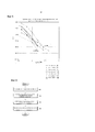
[145] Фиг. 9 - график, иллюстрирующий кодовую скорость, когда количество битов дополнительной четности вычисляется с использованием Уравнения (15), в соответствии с вариантом осуществления настоящего изобретения.[145] FIG. 9 is a graph illustrating a code rate when the number of bits of additional parity is calculated using Equation (15), in accordance with an embodiment of the present invention.
[146] В частности, кодовая скорость вычисляется с использованием Уравнения (19).[146] In particular, the code rate is calculated using Equation (19).
[147] 
[148] В Уравнении (19) Ntx_parity указывает количество битов четности в первой части 814 из фиг. 8, и Nldpc + MIR - Npunc=6480-Npunc. Nadd_parity указывает количество битов дополнительной четности в части 816 из фиг. 8.[148] In Equation (19), N tx_parity indicates the number of parity bits in the
[149] На фиг. 9 Дополнительная четность (AP)=0 соответствует кодовой скорости для I0=0, при которой дополнительная четность не используется, AP=1 соответствует кодовой скорости для I1=1, AP=2 соответствует кодовой скорости для I2=2, и AP=3 соответствует кодовой скорости для I3=3.[149] In FIG. 9 Additional parity (AP) = 0 corresponds to a code rate for I 0 = 0, at which additional parity is not used, AP = 1 corresponds to a code rate for I 1 = 1, AP = 2 corresponds to a code rate for I 2 = 2, and AP = 3 corresponds to the code rate for I 3 = 3.
[150] В соответствии с другим вариантом осуществления настоящего изобретения биты 804 четности с IR в LDPC-коде на фиг. 8 могут использоваться выборочно. То есть биты 802 четности предпочтительно формируются для битов входного информационного слова, а биты 804 четности с IR могут формироваться, только когда необходима четность с IR, посредством этого повышая эффективность кодирования/декодирования.[150] According to another embodiment of the present invention,
[151] Как описано выше, биты 802 четности предпочтительно формируются для входных информационных битов, и для битов 802 четности Npunc может вычисляться на основе Уравнения (7), как показано в Уравнении (20).[151] As described above,
[152] 
[153] В Уравнении (20), если Npunc является положительным целым числом, то формируются только биты 802 четности, и исключается только Npunc битов четности из битов 802 четности. Однако, если Npunc является отрицательным значением, то формируются биты 802 четности и биты 804 четности с IR, а затем исключается только (MIR + Npunc) битов из битов 804 четности с IR.[153] In Equation (20), if N punc is a positive integer, then only
[154] В соответствии с другим вариантом осуществления настоящего изобретения исключается Npunc (полученное с использованием Уравнений с (10) по (12), на основе Уравнения (20)) битов четности.[154] In accordance with another embodiment of the present invention, N punc (obtained using Equations (10) to (12) based on Equation (20)) of parity bits is excluded.
[155] Фиг. 10 - блок-схема последовательности операций, иллюстрирующая процедуру для определения количества двух типов битов четности в соответствии с вариантом осуществления настоящего изобретения.[155] FIG. 10 is a flowchart illustrating a procedure for determining the number of two types of parity bits in accordance with an embodiment of the present invention.
[156] Ссылаясь на фиг. 10, на этапе 1000 количество битов четности, которые необходимо исключить, вычисляется с использованием Уравнений (7) и (8) или Уравнений с (9) по (12). На этапе 1002 определяются параметры α, Il и Ntx_parity, которые используются в Уравнении (13), (15) и (17). На этапе 1002 могут использоваться уже определенные α или Il, и Il выражается в виде K в Уравнениях (17) и (18). Как описано выше, K может указываться отдельной сигнализацией "L1_AP_RATIO".[156] Referring to FIG. 10, in
[157] На этапе 1004 количество битов дополнительной четности, Nadd_parity, определяется на основе Уравнения (13) или Уравнений (17) и (18), используя параметры, определенные на этапе 1002. На этапе 1006 биты дополнительной четности конфигурируются в соответствии с вычисленным количеством битов дополнительной четности.[157] In
[158] Фиг. 11 - блок-схема стороны передачи в соответствии с вариантом осуществления настоящего изобретения.[158] FIG. 11 is a block diagram of a transmission side in accordance with an embodiment of the present invention.
[159] Ссылаясь на фиг. 11, сторона передачи включает в себя кодер 1101, исключающий блок 1103, контроллер 1105, модулятор 1107, радиочастотный (РЧ) процессор 1109 и, выборочно, блок 1111 конфигурирования дополнительной четности.[159] Referring to FIG. 11, the transmission side includes an
[160] Кодер 1101 выводит кодированные биты, сформированные путем кодирования битов информационного слова для передачи. Например, когда используется BCH/LDPC-код, кодер 1101 кодирует информационные биты BCH, содержащие Kbch битов, чтобы сформировать кодовое слово BCH, содержащее Kldpc битов. После этого кодер 1101 выполняет LDPC-кодирование над кодовым словом BCH, соответственно формируя и выводя кодовое слово LPDC, содержащее Nldpc битов.[160] Encoder 1101 outputs encoded bits generated by encoding bits of an information word for transmission. For example, when a BCH / LDPC code is used,
[161] В качестве альтернативы кодер 1101 формирует и выводит кодовое слово LPDC, содержащее (Nldpc + MIR) битов.[161] Alternatively, the
[162] Хотя и не проиллюстрировано, информационные биты BCH, содержащие Kbch битов, могут конфигурироваться путем заполнения (Kbch - Ksig) "0"-ыми битами Ksig входных информационных битов. Заполненные (Kbch - Ksig) "0"-ых битов не должны передаваться.[162] Although not illustrated, BCH information bits containing K bch bits can be configured by filling (K bch - K sig ) with the “0” bits K sig of the input information bits. Filled (K bch - K sig ) "0" bits should not be transmitted.
[163] Исключающий блок 1103 исключает кодовое слово, предоставленное от кодера 1101, в соответствии с шаблоном исключения и длиной битов исключения (Kbch - Ksig), которые предоставляются от контроллера 1105. Контроллер 1105 вычисляет длину битов исключения в соответствии с количеством информационных битов для управления исключающим блоком 1103. Например, контроллер 1105 определяет A и B в соответствии с количеством входных информационных битов (или количеством сигнальных битов) для передачи на стороне передачи и предоставляет определенные A и B исключающему блоку 1103.[163] The
[164] В качестве альтернативы контроллер 1105 получает количество битов, которые необходимо исключить, из определенных параметров A и B и предоставляет исключающему блоку 1103 полученное количество битов, которые необходимо исключить. Модулятор 1107 в соответствии с соответствующей схемой модуляции модулирует и выводит сигнал, предоставленный от исключающего блока 1103. РЧ-блок 1109 преобразует модулированный сигнал, предоставленный от модулятора 1107, в высокочастотный сигнал и передает высокочастотный сигнал посредством антенны.[164] Alternatively, the
[165] Если должны передаваться биты дополнительной четности, то контроллер 1105 определяет количество битов дополнительной четности, как проиллюстрировано на фиг. 10, и предоставляет определенное количество битов дополнительной четности блоку 1111 конфигурирования дополнительной четности. Блок 1111 конфигурирования дополнительной четности конфигурирует биты дополнительной четности и предоставляет их модулятору 1107. Следует отметить, что дополнительные четности, сформированные в текущем кадре, передаются посредством предыдущего кадра.[165] If additional parity bits are to be transmitted, then the
[166] Предполагая LDPC-кодирование (Nldpc, Kldpc), (Kldpc - Ksig) битов сокращается для длины входных информационных битов Ksig. Если каскадируется BCH-код, то (Kbch - Ksig) битов сокращается для длины информационных битов BCH Kbch.[166] Assuming the LDPC coding (N ldpc , K ldpc ), (K ldpc - K sig ) bits are shortened for the length of the input information bits K sig . If the BCH code is cascaded, then the (K bch - K sig ) bits are shortened for the length of the BCH information bits K bch .
[167] Фиг. 12 - блок-схема стороны приема в соответствии с вариантом осуществления настоящего изобретения.[167] FIG. 12 is a block diagram of a receiving side according to an embodiment of the present invention.
[168] Ссылаясь на фиг. 12, сторона приема включает в себя РЧ-блок 1200, демодулятор 1202, сокращающий/исключающий процессор 1204, декодер 1206, контроллер 1208 и, выборочно, блок 1210 обработки дополнительной четности.[168] Referring to FIG. 12, the receiving side includes an
[169] РЧ-блок 1200 принимает сигнал, переданный от РЧ-блока 1109 стороны передачи, и предоставляет этот сигнал демодулятору 1202.[169] The
[170] Демодулятор 1202 демодулирует сигнал, предоставленный от РЧ-блока 1200, с использованием схемы демодуляции, соответствующей схеме модуляции, использованной в модуляторе 1107 стороны передачи. Например, демодулятор 1202 получает логарифмическое отношение правдоподобия (LLR) путем логарифмирования отношения вероятности того, что каждый бит равен 1, к вероятности того, что каждый бит равен 0, для каждого из сокращенных/исключенных кодированных битов и битов дополнительной четности, переданных от модулятора 1107, и предоставляет полученное LLR сокращающему/исключающему процессору 1204 и блоку 1210 обработки дополнительной четности. Процессор 1201 дополнительной четности является необязательным в том, что он не используется, когда не принимается дополнительная четность.[170] A
[171] Сокращающий/исключающий процессор 1204 принимает выходной сигнал демодулятора 1202, формирует значения, соответствующие сокращению и исключению по отношению к битам, сокращенным и исключенным стороной передачи, и заполняет этими значениями выходной сигнал демодулятора 1202. Например, для сокращенного бита значение LLR равно (+) или (-) максимальному значению среди входных значений декодера, а для исключенного бита значение LLR равно "0". Сокращающий/исключающий процессор 1204 принимает от контроллера 1208 информацию о количестве сокращенных и исключенных битов и индексе. То есть контроллер 1208 вычисляет длину битов исключения в соответствии с количеством информационных битов кодера 1101 стороны передачи и управляет сокращающим/исключающим процессором 1204.[171] The abbreviation /
[172] Например, контроллер 1208 определяет A и B в соответствии с количеством битов сигнальной информации для передачи на стороне передачи, как проиллюстрировано на фиг. 6, и предоставляет определенные A и B сокращающему/исключающему процессору 1204.[172] For example, the
[173] В качестве альтернативы контроллер 1208 получает количество битов, которые необходимо исключить, из определенных параметров A и B и предоставляет сокращающему/исключающему процессору 1204 полученное количество битов, которые необходимо исключить. Информация о количестве входных информационных битов, введенных в кодер стороны передачи, может передаваться контроллеру 1208 приемника посредством, например, дополнительной сигнализации.[173] Alternatively, the
[174] Декодер 1206 принимает и декодирует выходные значения сокращающего/исключающего процессора 1204, чтобы восстановить биты информационного слова. Например, когда используется BCH/LDPC-код, декодер 1206 принимает Nldpc или (Nldpc+MIR) значений LLR и выполняет LDPC-декодирование над ними, чтобы восстановить Kldpc битов, а затем восстанавливает Kbch битов информационного слова посредством BCH-декодирования.[174] The
[175] Когда передаются биты дополнительной четности, контроллер 1208 определяет количество битов дополнительной четности, как проиллюстрировано на фиг. 10, и предоставляет определенное количество битов дополнительной четности блоку 1210 обработки дополнительной четности. Блок 1210 обработки дополнительной четности принимает от демодулятора 1202 значения LLR для битов дополнительной четности, сформированных стороной передачи, и предоставляет значения LLR декодеру 1206. Декодер 1206 выполняет декодирование с использованием значений, предоставленных от сокращающего/исключающего процессора 1204, и значений, предоставленных от блока 1210 обработки дополнительной четности. Следует отметить, что дополнительные четности, принятые в текущем кадре, используются при декодировании следующего кадра в соответствии с обработкой на передатчике. То есть при декодировании кода, принятого в текущем кадре, используются биты дополнительной четности, принятые в предыдущем кадре.[175] When the additional parity bits are transmitted, the
[176] В соответствии с вышеописанными вариантами осуществления настоящего изобретения с помощью адаптивного выбора скорости сокращения/исключения на основе информации о состоянии канала, необходимой в вещательной системе/системе связи, поддерживается сходная эффективность независимо от длины информационного слова, посредством этого поддерживая стабильность системы.[176] In accordance with the above-described embodiments of the present invention, by adaptively selecting a reduction / elimination rate based on the channel status information needed in the broadcast / communication system, similar efficiency is maintained regardless of the length of the information word, thereby maintaining system stability.
[177] Несмотря на то, что настоящее изобретение подробно показано и описано со ссылкой на его некоторые варианты осуществления, средним специалистам в данной области техники будет понятно, что в нем могут быть сделаны различные изменения в форме и деталях без отклонения от сущности и объема настоящего изобретения, которые определены нижеследующей формулой изобретения и ее эквивалентами.[177] Although the present invention has been shown and described in detail with reference to some of its embodiments, it will be understood by those of ordinary skill in the art that various changes in form and detail can be made therein without departing from the spirit and scope of the present inventions as defined by the following claims and their equivalents.
Claims (55)


Applications Claiming Priority (5)
| Application Number | Priority Date | Filing Date | Title |
|---|---|---|---|
| KR10-2011-0087464 | 2011-08-30 | ||
| KR20110087464 | 2011-08-30 | ||
| KR10-2012-0005565 | 2012-01-18 | ||
| KR1020120005565A KR101922555B1 (en) | 2011-08-30 | 2012-01-18 | Method and apparatus transmitting and receiving information in broadcasting/communication system |
| PCT/KR2012/006516 WO2013032156A1 (en) | 2011-08-30 | 2012-08-16 | Method and apparatus for transmitting and receiving information in a broadcasting/communication system |
Publications (2)
| Publication Number | Publication Date |
|---|---|
| RU2014112217A RU2014112217A (en) | 2015-10-10 |
| RU2609067C2 true RU2609067C2 (en) | 2017-01-30 |
Family
ID=48176721
Family Applications (1)
| Application Number | Title | Priority Date | Filing Date |
|---|---|---|---|
| RU2014112217A RU2609067C2 (en) | 2011-08-30 | 2012-08-16 | Method and apparatus for transmitting and receiving information in broadcasting/communication system |
Country Status (6)
| Country | Link |
|---|---|
| JP (1) | JP5964969B2 (en) |
| KR (1) | KR101922555B1 (en) |
| CN (1) | CN103765781B (en) |
| AU (1) | AU2012302460B2 (en) |
| IN (1) | IN2014CN02200A (en) |
| RU (1) | RU2609067C2 (en) |
Families Citing this family (21)
| Publication number | Priority date | Publication date | Assignee | Title |
|---|---|---|---|---|
| KR102191872B1 (en) * | 2013-07-05 | 2020-12-16 | 엘지전자 주식회사 | Apparatus for transmitting broadcast signals, apparatus for receiving broadcast signals, method for transmitting broadcast signals and method for receiving broadcast signals |
| WO2015041479A1 (en) * | 2013-09-18 | 2015-03-26 | Samsung Electronics Co., Ltd. | Transmitter and puncturing method thereof |
| KR102177807B1 (en) * | 2014-08-22 | 2020-11-11 | 삼성전자주식회사 | Method and apparatus for shortening and puncturing of non binary codes |
| WO2016129975A2 (en) | 2015-02-13 | 2016-08-18 | Samsung Electronics Co., Ltd. | Transmitter and additional parity generating method thereof |
| KR101800423B1 (en) * | 2015-02-13 | 2017-11-23 | 삼성전자주식회사 | Transmitter and additional parity generating method thereof |
| KR101776273B1 (en) * | 2015-02-25 | 2017-09-07 | 삼성전자주식회사 | Transmitter and method for generating additional parity thereof |
| MY196159A (en) | 2015-02-25 | 2023-03-17 | Samsung Electronics Co Ltd | Transmitter And Method For Generating Additional Parity Thereof |
| KR102453474B1 (en) | 2015-02-27 | 2022-10-14 | 한국전자통신연구원 | Apparatus of parity interleaving for encoding variable-length signaling information and method using the same |
| WO2016137204A1 (en) | 2015-02-27 | 2016-09-01 | 한국전자통신연구원 | Parity interleaving apparatus for encoding fixed-length signaling information, and parity interleaving method using same |
| WO2016137253A1 (en) * | 2015-02-27 | 2016-09-01 | 한국전자통신연구원 | Parity puncturing device for fixed-length signaling information encoding, and parity puncturing method using same |
| KR102453473B1 (en) * | 2015-02-27 | 2022-10-14 | 한국전자통신연구원 | Apparatus of parity puncturing for encoding fixed-length signaling information and method using the same |
| WO2016137255A1 (en) * | 2015-02-27 | 2016-09-01 | 한국전자통신연구원 | Parity puncturing device for variable-length signaling information encoding, and parity puncturing method using same |
| KR102453476B1 (en) | 2015-02-27 | 2022-10-14 | 한국전자통신연구원 | Apparatus of parity interleaving for encoding fixed-length signaling information and method using the same |
| KR102453472B1 (en) | 2015-02-27 | 2022-10-14 | 한국전자통신연구원 | Apparatus of parity puncturing for encoding variable-length signaling information and method using the same |
| WO2016137254A1 (en) * | 2015-02-27 | 2016-09-01 | 한국전자통신연구원 | Parity interleaving apparatus for encoding variable-length signaling information and parity interleaving method using same |
| WO2016140512A1 (en) | 2015-03-02 | 2016-09-09 | Samsung Electronics Co., Ltd. | Transmitter and puncturing method thereof |
| KR101800414B1 (en) * | 2015-03-02 | 2017-11-23 | 삼성전자주식회사 | Transmitter and additional parity generating method thereof |
| US10291256B2 (en) | 2015-03-02 | 2019-05-14 | Samsung Electronics Co., Ltd. | Transmitter and method for generating additional parity thereof |
| MY182123A (en) | 2015-03-02 | 2021-01-18 | Samsung Electronics Co Ltd | Transmitter and segmentation method thereof |
| KR101800417B1 (en) * | 2015-03-02 | 2017-11-23 | 삼성전자주식회사 | Transmitter and segmentation method thereof |
| KR101800420B1 (en) * | 2015-03-02 | 2017-11-23 | 삼성전자주식회사 | Transmitter and puncturing method thereof |
Citations (4)
| Publication number | Priority date | Publication date | Assignee | Title |
|---|---|---|---|---|
| US20060123277A1 (en) * | 2004-11-23 | 2006-06-08 | Texas Instruments Incorporated | Simplified decoding using structured and punctured LDPC codes |
| WO2009110739A2 (en) * | 2008-03-03 | 2009-09-11 | Samsung Electronics Co., Ltd. | Method for encoding control information in a wireless communication system, and method and apparatus for transmitting and receiving the control information |
| RU2392747C2 (en) * | 2005-01-24 | 2010-06-20 | Квэлкомм Инкорпорейтед | Analyser for several data streams in communication system |
| US20110119568A1 (en) * | 2009-11-18 | 2011-05-19 | Samsung Electronics Co., Ltd. | Method and apparatus for transmitting and receiving data in a communication system |
Family Cites Families (11)
| Publication number | Priority date | Publication date | Assignee | Title |
|---|---|---|---|---|
| EP1317070A1 (en) * | 2001-12-03 | 2003-06-04 | Mitsubishi Electric Information Technology Centre Europe B.V. | Method for obtaining from a block turbo-code an error correcting code of desired parameters |
| WO2006039801A1 (en) * | 2004-10-12 | 2006-04-20 | Nortel Networks Limited | System and method for low density parity check encoding of data |
| US7661037B2 (en) * | 2005-10-27 | 2010-02-09 | Samsung Electronics Co., Ltd. | LDPC concatenation rules for IEEE 802.11n systems |
| US7584406B2 (en) * | 2005-12-20 | 2009-09-01 | Samsung Electronics Co., Ltd. | LDPC concatenation rules for IEEE 802.11n system with packets length specific in octets |
| US8166367B2 (en) * | 2007-12-06 | 2012-04-24 | Samsung Electronics Co., Ltd. | Method and apparatus for encoding and decoding channel in a communication system using low-density parity-check codes |
| KR101502623B1 (en) * | 2008-02-11 | 2015-03-16 | 삼성전자주식회사 | Apparatus and method for channel encoding and decoding in communication system using low-density parity-check codes |
| KR20090095432A (en) * | 2008-03-03 | 2009-09-09 | 삼성전자주식회사 | Apparatus and method for channel encoding and decoding in communication system using low-density parity-check codes |
| KR20090094738A (en) * | 2008-03-03 | 2009-09-08 | 삼성전자주식회사 | Apparatus and method for encoding signalling information in radio communication system |
| CN101630989B (en) * | 2008-07-14 | 2012-10-03 | 上海华为技术有限公司 | Method and device for data transmission and communication system |
| CN101753264B (en) * | 2008-12-18 | 2013-06-12 | 华为技术有限公司 | Acquisition method and device for evaluating threshold value of perforation pattern performance |
| CN101567697B (en) * | 2009-05-25 | 2012-12-12 | 普天信息技术研究院有限公司 | Coder and method for coding rate-compatible low-density parity-check codes |
-
2012
- 2012-01-18 KR KR1020120005565A patent/KR101922555B1/en active IP Right Grant
- 2012-08-16 AU AU2012302460A patent/AU2012302460B2/en not_active Ceased
- 2012-08-16 JP JP2014528262A patent/JP5964969B2/en active Active
- 2012-08-16 IN IN2200CHN2014 patent/IN2014CN02200A/en unknown
- 2012-08-16 CN CN201280041485.8A patent/CN103765781B/en active Active
- 2012-08-16 RU RU2014112217A patent/RU2609067C2/en active
Patent Citations (4)
| Publication number | Priority date | Publication date | Assignee | Title |
|---|---|---|---|---|
| US20060123277A1 (en) * | 2004-11-23 | 2006-06-08 | Texas Instruments Incorporated | Simplified decoding using structured and punctured LDPC codes |
| RU2392747C2 (en) * | 2005-01-24 | 2010-06-20 | Квэлкомм Инкорпорейтед | Analyser for several data streams in communication system |
| WO2009110739A2 (en) * | 2008-03-03 | 2009-09-11 | Samsung Electronics Co., Ltd. | Method for encoding control information in a wireless communication system, and method and apparatus for transmitting and receiving the control information |
| US20110119568A1 (en) * | 2009-11-18 | 2011-05-19 | Samsung Electronics Co., Ltd. | Method and apparatus for transmitting and receiving data in a communication system |
Also Published As
| Publication number | Publication date |
|---|---|
| AU2012302460B2 (en) | 2016-09-08 |
| CN103765781A (en) | 2014-04-30 |
| AU2012302460A1 (en) | 2014-03-06 |
| RU2014112217A (en) | 2015-10-10 |
| KR101922555B1 (en) | 2018-11-28 |
| CN103765781B (en) | 2017-05-31 |
| JP2014525710A (en) | 2014-09-29 |
| JP5964969B2 (en) | 2016-08-03 |
| KR20130024704A (en) | 2013-03-08 |
| IN2014CN02200A (en) | 2015-05-29 |
Similar Documents
| Publication | Publication Date | Title |
|---|---|---|
| RU2609067C2 (en) | Method and apparatus for transmitting and receiving information in broadcasting/communication system | |
| US9479290B2 (en) | Method and apparatus for transmitting and receiving information in a broadcasting/communication system | |
| JP5712251B2 (en) | Method for encoding control information in a communication system and method and apparatus for transmitting and receiving the control information | |
| EP2502378B1 (en) | Transmitter and transmission method for broadcasting data in a broadcasting system providing incremental redundancy | |
| US8887030B2 (en) | Encoder and encoding method providing incremental redundancy | |
| EP2490337B1 (en) | Method and apparatus for encoding and decoding in a communication system using low-density parity check codes | |
| KR101651683B1 (en) | Apparatus and method for channel encoding in a communication system | |
| KR101972131B1 (en) | Apparatus and method for transmitting and receiving data in communication system | |
| JP5357250B2 (en) | System and method for preventing non-uniform errors using embedded coding | |
| US9548881B2 (en) | Method and apparatus for transmitting and receiving data in broadcasting system | |
| US10965398B2 (en) | Transmitter, receiver, and signal processing method thereof | |
| EP2502351B1 (en) | Receiver and receiving method for receiving data in a broadcasting system using incremental redundancy | |
| JP2010157990A (en) | Wireless transmitting apparatus and method, and wireless receiving apparatus and method | |
| KR101587340B1 (en) | Method for encoding contorl information in a communication system and transmission/reception method and apparatus thereof | |
| WO2011104144A1 (en) | Encoder and encoding method providing incremental redundancy |