RU2608564C2 - Wires and cables support and fixing device - Google Patents
Wires and cables support and fixing device Download PDFInfo
- Publication number
- RU2608564C2 RU2608564C2 RU2014113327A RU2014113327A RU2608564C2 RU 2608564 C2 RU2608564 C2 RU 2608564C2 RU 2014113327 A RU2014113327 A RU 2014113327A RU 2014113327 A RU2014113327 A RU 2014113327A RU 2608564 C2 RU2608564 C2 RU 2608564C2
- Authority
- RU
- Russia
- Prior art keywords
- support
- base
- cable
- channel
- supporting
- Prior art date
Links
- 238000009434 installation Methods 0.000 claims description 2
- 238000000034 method Methods 0.000 claims 1
- 230000014759 maintenance of location Effects 0.000 abstract 1
- 239000000126 substance Substances 0.000 abstract 1
- 230000001681 protective effect Effects 0.000 description 3
- 239000004743 Polypropylene Substances 0.000 description 1
- XAGFODPZIPBFFR-UHFFFAOYSA-N aluminium Chemical compound [Al] XAGFODPZIPBFFR-UHFFFAOYSA-N 0.000 description 1
- 229910052782 aluminium Inorganic materials 0.000 description 1
- 238000005516 engineering process Methods 0.000 description 1
- 230000003993 interaction Effects 0.000 description 1
- 238000012423 maintenance Methods 0.000 description 1
- 239000000463 material Substances 0.000 description 1
- 238000000465 moulding Methods 0.000 description 1
- 230000002093 peripheral effect Effects 0.000 description 1
- 239000004033 plastic Substances 0.000 description 1
- -1 polypropylene Polymers 0.000 description 1
- 229920001155 polypropylene Polymers 0.000 description 1
- 238000000926 separation method Methods 0.000 description 1
- 239000003351 stiffener Substances 0.000 description 1
Images
Classifications
-
- H—ELECTRICITY
- H02—GENERATION; CONVERSION OR DISTRIBUTION OF ELECTRIC POWER
- H02G—INSTALLATION OF ELECTRIC CABLES OR LINES, OR OF COMBINED OPTICAL AND ELECTRIC CABLES OR LINES
- H02G3/00—Installations of electric cables or lines or protective tubing therefor in or on buildings, equivalent structures or vehicles
- H02G3/26—Installations of cables, lines, or separate protective tubing therefor directly on or in walls, ceilings, or floors
-
- F—MECHANICAL ENGINEERING; LIGHTING; HEATING; WEAPONS; BLASTING
- F16—ENGINEERING ELEMENTS AND UNITS; GENERAL MEASURES FOR PRODUCING AND MAINTAINING EFFECTIVE FUNCTIONING OF MACHINES OR INSTALLATIONS; THERMAL INSULATION IN GENERAL
- F16L—PIPES; JOINTS OR FITTINGS FOR PIPES; SUPPORTS FOR PIPES, CABLES OR PROTECTIVE TUBING; MEANS FOR THERMAL INSULATION IN GENERAL
- F16L3/00—Supports for pipes, cables or protective tubing, e.g. hangers, holders, clamps, cleats, clips, brackets
- F16L3/22—Supports for pipes, cables or protective tubing, e.g. hangers, holders, clamps, cleats, clips, brackets specially adapted for supporting a number of parallel pipes at intervals
- F16L3/23—Supports for pipes, cables or protective tubing, e.g. hangers, holders, clamps, cleats, clips, brackets specially adapted for supporting a number of parallel pipes at intervals for a bundle of pipes or a plurality of pipes placed side by side in contact with each other
- F16L3/233—Supports for pipes, cables or protective tubing, e.g. hangers, holders, clamps, cleats, clips, brackets specially adapted for supporting a number of parallel pipes at intervals for a bundle of pipes or a plurality of pipes placed side by side in contact with each other by means of a flexible band
-
- H—ELECTRICITY
- H02—GENERATION; CONVERSION OR DISTRIBUTION OF ELECTRIC POWER
- H02G—INSTALLATION OF ELECTRIC CABLES OR LINES, OR OF COMBINED OPTICAL AND ELECTRIC CABLES OR LINES
- H02G3/00—Installations of electric cables or lines or protective tubing therefor in or on buildings, equivalent structures or vehicles
- H02G3/02—Details
- H02G3/04—Protective tubing or conduits, e.g. cable ladders or cable troughs
- H02G3/0406—Details thereof
-
- H—ELECTRICITY
- H02—GENERATION; CONVERSION OR DISTRIBUTION OF ELECTRIC POWER
- H02G—INSTALLATION OF ELECTRIC CABLES OR LINES, OR OF COMBINED OPTICAL AND ELECTRIC CABLES OR LINES
- H02G3/00—Installations of electric cables or lines or protective tubing therefor in or on buildings, equivalent structures or vehicles
- H02G3/30—Installations of cables or lines on walls, floors or ceilings
-
- Y—GENERAL TAGGING OF NEW TECHNOLOGICAL DEVELOPMENTS; GENERAL TAGGING OF CROSS-SECTIONAL TECHNOLOGIES SPANNING OVER SEVERAL SECTIONS OF THE IPC; TECHNICAL SUBJECTS COVERED BY FORMER USPC CROSS-REFERENCE ART COLLECTIONS [XRACs] AND DIGESTS
- Y10—TECHNICAL SUBJECTS COVERED BY FORMER USPC
- Y10T—TECHNICAL SUBJECTS COVERED BY FORMER US CLASSIFICATION
- Y10T29/00—Metal working
- Y10T29/49—Method of mechanical manufacture
- Y10T29/49826—Assembling or joining
- Y10T29/49947—Assembling or joining by applying separate fastener
- Y10T29/49948—Multipart cooperating fastener [e.g., bolt and nut]
- Y10T29/4995—Nonthreaded
Landscapes
- Engineering & Computer Science (AREA)
- Architecture (AREA)
- Civil Engineering (AREA)
- Structural Engineering (AREA)
- General Engineering & Computer Science (AREA)
- Mechanical Engineering (AREA)
- Installation Of Indoor Wiring (AREA)
- Supports For Pipes And Cables (AREA)
Abstract
Description
Предметом настоящего изобретения является опорное и фиксирующее устройство для кабелей или жгутов проводов в удлиненном канале; данное устройство является полезным для сложных систем электроснабжения, например, в летательных аппаратах.The subject of the present invention is a support and fixing device for cables or wiring harnesses in an elongated channel; This device is useful for complex power supply systems, for example, in aircraft.
В сложных системах электроснабжения жгуты электрических проводов, связанных вместе кабельными стяжками в различных точках с интервалом по длине, укладывают в желобах или каналах для предотвращения их запутывания, повреждения или нежелательного взаимодействия с другими элементами системы. При сборке провода могут вставляться в удлиненные желоба с одной стороны или фиксироваться в открытых каналах. Последний вариант является предпочтительным для некоторых современных систем. Использование подобных открытых каналов упрощает доступ и проведение техобслуживания, но оно означает, что должны быть приняты дополнительные меры для фиксации проводов в каналах при одновременном снижении риска перетирания или какого-либо другого повреждения проводов.In complex power supply systems, cable harnesses connected together by cable ties at various points with an interval in length are laid in gutters or channels to prevent tangling, damage, or undesired interaction with other elements of the system. During assembly, the wires can be inserted into elongated grooves on one side or fixed in open channels. The latter option is preferred for some modern systems. The use of such open channels simplifies access and maintenance, but it means that additional measures must be taken to fix the wires in the channels while reducing the risk of fraying or any other damage to the wires.
Согласно первому аспекту настоящего изобретения предлагается двухкомпонентное устройство для укладки и фиксации кабеля или жгута проводов в канале, содержащее опорную часть, включающую в себя опорную поверхность с удлиненным углублением и рейку для кабельной стяжки, проходящую поперек и над указанным углублением, образующую под собой канал для кабельной стяжки, и базовую часть с основанием, содержащим средства для крепления его к нижней части кабельного канала; опорная часть крепится к базовой части, например, с помощью фрикционной посадки или защелкивания; в базовой части также предусмотрен соединительная рейка, проходящая поперек и над ее основанием, форма и положение которой обеспечивают ее точное нахождение непосредственно под соединительной рейкой опорной части, так что кабельная стяжка может проходить сквозь углубленное отверстие в опорной части вокруг обеих вышеуказанных соединительных реек, обеспечивая крепление жгута проводов, уложенного на профилированной поверхности опорной части.According to a first aspect of the present invention, there is provided a two-component device for laying and fixing a cable or wiring harness in a channel, comprising a support portion including a support surface with an elongated recess and a cable tie rail extending transversely and above said recess, forming a cable duct underneath screeds, and the base part with a base containing means for attaching it to the bottom of the cable channel; the supporting part is attached to the base part, for example, by means of a friction fit or snap; a connecting rail is also provided in the base part, extending transversely and above its base, the shape and position of which ensures its exact location directly below the connecting rail of the supporting part, so that the cable tie can pass through a recessed hole in the supporting part around both of the above connecting rails, providing fastening wiring harness laid on the profiled surface of the supporting part.
Опорная поверхность предпочтительно имеет центральную вогнутую часть, проходящую в направлении указанного выреза и выпуклых частей с обеих сторон указанного выреза, и соединительную рейку, проходящую в поперечном направлении.The abutment surface preferably has a central concave portion extending in the direction of said notch and convex portions on both sides of said notch and a connecting rail extending in the transverse direction.
Опорная часть предпочтительно имеет удлиненную форму с удлиненным вырезом, проходящим в продольном направлении, и рейку для кабельной стяжки, проходящую под прямым углом к продольному направлению.The support portion preferably has an elongated shape with an elongated notch extending in the longitudinal direction and a rail for the cable tie extending at right angles to the longitudinal direction.
Опорная часть на своей нижней поверхности предпочтительно имеет пару выступов для соединения с соответствующими соединительными элементами нижней части, предпочтительно расположенными на противоположных сторонах удлиненного выреза. Данные выступы могут иметь цилиндрическую форму.The supporting part on its lower surface preferably has a pair of protrusions for connection with the corresponding connecting elements of the lower part, preferably located on opposite sides of the elongated notch. These protrusions may have a cylindrical shape.
Базовая часть также имеет предпочтительно удлиненную форму с выступающими вверх выступами на обеих сторонах, служащими для соединения с направленными вниз выступами верхней части за счет трения или с помощью защелкивающегося механизма. Предпочтительно выступающие элементы базовой части представляют собой цилиндрические вырезы, каждый из которых окружает отверстие в основании, служащее для крепления к нижней части проводного канала.The base part also preferably has an elongated shape with upwardly projecting protrusions on both sides for connecting to the downwardly projecting protrusions of the upper part by friction or by a snap mechanism. Preferably, the protruding elements of the base part are cylindrical cutouts, each of which surrounds a hole in the base, used to attach to the lower part of the wire channel.
Опорная часть двухкомпонентной опоры имеет предпочтительно седловидную форму, т.е. является существенно арковидной в вертикальном поперечном сечении при взгляде с одного края, причем ее поверхность имеет минимальный радиус кривизны в середине, совпадающей с местом расположения соединительной рейки для кабельной стяжки, и данный радиус кривизны постепенно увеличивается по мере удаления в обе стороны от соединительной рейки. Ширина опорной части также предпочтительно увеличивается по мере удаления в обе стороны от соединительной рейки.The supporting part of the two-component support is preferably saddle-shaped, i.e. is substantially arch-shaped in a vertical cross section when viewed from one edge, and its surface has a minimum radius of curvature in the middle that coincides with the location of the connecting rail for the cable tie, and this radius of curvature gradually increases with distance to both sides of the connecting rail. The width of the support portion also preferably increases as it moves away on both sides of the connecting rail.
Ниже приводится описание предпочтительных вариантов осуществления настоящего изобретения со ссылками на приложенные чертежи, а именно:The following is a description of preferred embodiments of the present invention with reference to the attached drawings, namely:
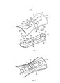
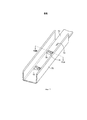
Фиг. 1 - вид в перспективе (вид сверху) двухкомпонентного поддерживающего и фиксирующего устройства согласно настоящему изобретению, две части которого разъединены;FIG. 1 is a perspective view (top view) of a two-component support and fixing device according to the present invention, the two parts of which are disconnected;
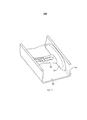
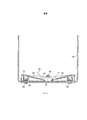
Фиг. 2 - вид в перспективе нижней части поддерживающего устройства, показанного на Фиг.1;FIG. 2 is a perspective view of the bottom of the support device shown in FIG. 1;
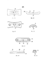
Фиг. 3А, 3В, 3С и 3D - соответственно вид сверху, вид сбоку, вид снизу и вид с торца поддерживающей части устройства, показанного на Фиг. 1;FIG. 3A, 3B, 3C and 3D are, respectively, a top view, a side view, a bottom view, and an end view of the supporting part of the device shown in FIG. one;
Фиг. 4А, 4В и 4С - соответственно вид сверху, вид сбоку и вид с торца базовой части устройства, представленного на Фиг. 1;FIG. 4A, 4B and 4C, respectively, a top view, a side view and an end view of the base part of the device shown in FIG. one;
Фиг. 5 - вид в перспективе, демонстрирующий поддерживающее и фиксирующее устройство в собранном виде по второму варианту осуществления изобретения, установленное в открытом проводном канале;FIG. 5 is a perspective view showing an assembled support and fixing device according to a second embodiment of the invention mounted in an open wire channel;
Фиг. 6 - вид в перспективе с частичным разрезом поддерживающего и фиксирующего устройства для проводов согласно настоящему изобретению, установленного в проводном канале и поддерживающего жгут проводов, скрепленный кабельной стяжкой;FIG. 6 is a partially cutaway perspective view of a support and fixing device for wires according to the present invention installed in a wire channel and supporting a wire harness fastened with a cable tie;
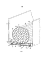
Фиг. 7 - вид в перспективе пары опор и фиксирующих устройств согласно другому варианту осуществления изобретения, установленных в проводном канале;FIG. 7 is a perspective view of a pair of supports and fixing devices according to another embodiment of the invention installed in a wire channel;
Фиг. 8 - вертикальный разрез по плоскости VIII-VIII на Фиг. 7.FIG. 8 is a vertical section along the plane VIII-VIII in FIG. 7.
Как показано на Фиг. 1-4, опора и фиксирующее устройство согласно настоящему изобретению содержит опорную часть 10 и базовую часть 12, соединяемые вместе и закрепляемые в проводном канале. Обе части предпочтительно выполнены из подходящего пластического материала типа полипропилена.As shown in FIG. 1-4, a support and a fixing device according to the present invention comprises a
Опорная часть 10 в целом имеет седловидную форму, удлиненная, с зауженной центральной частью 26 и расширенными концевыми частями 28. Поверхность 14 опорной части служит опорой для проводов или кабелей, и на ней не имеется каких-либо острых кромок, которые могли бы входить в контакт с проводами на опоре и повреждать их. Поверхность 14 изогнута вниз с каждой стороны продольной оси опорной части, причем радиус кривизны является наименьшим в центральной части 26 и постепенно увеличивается до максимального на концах 28.The
Удлиненный вырез 16 для кабельной стяжки, проходящий вдоль оси в центральной части опоры 10, соединяется рейкой 18, которая проходит в поперечном направлении через центр опоры. В вырезе выполнена пара наклонных плоскостей 15, наклоненных вниз в направлении друг к другу с противоположных сторон поверхности опоры, каждая из которых заканчивается более пологой секцией 17. Данные две секции 17 разделены интервалом 19 под рейкой 18.An elongated
На обратной стороне опорной части, как показано на Фиг.2, предусмотрены продольные ребра жесткости 22, выполненные заодно с данной деталью путем формования. На каждой стороне нижней части опоры выполнен круглый направленный вниз выступ 20 для зацепления с соответствующим круглым вырезом 34 на базовой части 12.On the reverse side of the support part, as shown in FIG. 2,
Как можно видеть из Фиг. 2, нижняя сторона 25 соединительной рейки 18 выполнена вогнутой, чтобы она могла входить в зацепление с соответственно выпуклой верхней стороной соответствующей соединительной рейки 30 на базовой части 12. Базовая часть включает в себя основание 42 удлиненной формы с закругленными торцами и нижнюю поверхность основания, загнутую вверх к верхней поверхности на каждом торце 44, чтобы основание можно было плотно устанавливать поперек нижней поверхности кабельного канала, имеющей соответствующим образом загнутые внутрь кромки.As can be seen from FIG. 2, the
Базовая часть также содержит периферийную стенку 32 с расположенными продольно прямыми параллельными боковыми сторонами, соединенными полукруглыми торцами, которые заканчиваются на небольшом расстоянии от торцов основания.The base part also comprises a
В основании имеется прямоугольное центральное отверстие 45, ограниченное противоположными нижними кромками параллельных секций стенки 32 и противоположными кромками 36 основания 42, каждая из которых наклонена вниз и образует кромку с нижней поверхностью основания.At the base there is a rectangular
Над отверстием 45 проходит соединительная рейка 30 поперек базовой части; каждый конец рейки опирается на одну из параллельных секций стенки 32.Above the
На дне каждого круглого углубления 34 имеется сквозное отверстие 40, выполненное в основании базовой части для крепления базовой части к нижней части кабельного канала, как будет пояснено ниже. Вокруг внутренней стенки каждого углубления 34 с интервалами расположены вертикальные ребра 35, в результате чего при сборке устройства направленные вниз выступы 20 верхней части с фрикционной посадкой могут соединяться с круглыми углублениями в базовой части. Шайбы 13 предназначены для установки внутри круглых вырезов 34 под выступами 20 опорной части.At the bottom of each
Как показано на Фиг. 1, верхняя поверхность соединительной рейки 18 имеет закругленную форму, а с каждой стороны канала 16 элементы 23 поверхности верхней части изогнуты вниз к кромке канала, чтобы устранить возможность образования острых кромок, которые могли бы повредить поверхность кабелей или проводов на опоре.As shown in FIG. 1, the upper surface of the connecting
На Фиг. 5 показано кабельное или проводное опорное устройство 52 согласно настоящему изобретению, установленное в проводном канале 50. Проводной канал является каналом открытого типа, соответствующим образом сформированным из экструдированного алюминия или выполненным по аналогичной технологии. Проводное опорное устройство 52 установлено поперек канала по его ширине и прикреплено к нижней части канала заклепками или аналогичным способом, что будет описано более подробно ниже. Опорное устройство, в принципе, аналогично представленному на Фиг. 1 - 4, за исключением того, что с одной стороны опорная часть имеет отформованную заодно защитную секцию 54, которая располагается вдоль одной боковой стенки 55 канала. Данная защитная секция служит для закрывания крепежных деталей, например, головок винтов. Обращенные внутрь поверхности защитной секции 54 все ровные и закругленные, что сделано с целью устранения возможности возникновения каких-либо острых кромок, которые могли бы повредить провода, находящиеся в канале.In FIG. 5 shows a cable or
Как показано на Фиг. 6, жгут проводов 65 уложен в проводном канале 60 и опирается на опору и фиксирующее устройство 10, 12, как было показано ранее на Фиг. 1 - 4.As shown in FIG. 6, the
Для установки данного устройства сначала помещают базовую часть 12 поперек нижней части канала таким образом, чтобы его отверстия 40 совпадали с отверстиями 68 в нижней части канала. В каждый вырез 34 базовой части вкладывают шайбу 13, после чего базовую часть с шайбами прикрепляют к нижней части канала заклепками 63 или аналогичными элементами, проходящими через отверстия 40 и 68.To install this device, first place the
Затем к базовой части прикрепляют опорную часть 10 опорного устройства таким образом, чтобы ее круглые направленные вниз выступы 20 вошли в вырезы 34 с натягом. Как видно из Фиг. 6, когда опорное устройство установлено, наклоненные вниз поверхности 17 выреза опорной части соприкасаются с направленными вниз кромками 36 основания базовой части, будучи обращенными друг к другу с разных сторон интервала 45, образуя, таким образом, относительно гладкие непрерывные кулачковые поверхности. Провода в жгуте 65 уложены поперек поверхности 14 верхней части опоры, а соединительная рейка 18 выступает вверх между двух находящихся рядом друг с другом проводов, помогая позиционировать жгут. Свободный конец кабельной стяжки 64 затем помещают в канал 16, зацепляя за одну из наклоненных вниз поверхностей 15 и толкают сверху таким образом, чтобы он прошел под комбинированными соединительными рейками 18, 30, проходящими поперек основания 62 канала, зацепляясь за наклонную кромку 36 основания базовой части, чтобы при дальнейшем его проталкивании он мог проскользнуть вверх по наклонным поверхностям 17, 15 на противоположной стороне выреза опорной части, выходящей из канала 16 на другой стороне жгута проводов. Затем два конца кабельной стяжки могут быть соединены, как это показано на Фиг. 6. Как видно из чертежа, в таком закрепленном положении кабельная стяжка не только удерживает жгут проводов вместе, но и крепит его одновременно к опоре и к основным элементам опоры, которая, в свою очередь, прикреплена к нижней части проводного канала.Then, the supporting
При поломке или повреждении какой-либо части проводной опоры или ее отделении от остальной части опоры, жгут проводов останется прикрепленным по меньшей мере к одной части опоры, поскольку кабельная стяжка проходит под обеими соединительными рейками. В положении, показанном на Фиг. 6, кабельная стяжка, по существу, удерживает вместе обе части опорного устройства, а также удерживает в связанном состоянии жгут проводов.In the event of breakage or damage to any part of the wire support or its separation from the rest of the support, the wire harness will remain attached to at least one part of the support, since the cable tie passes under both connecting rails. In the position shown in FIG. 6, the cable tie essentially holds both parts of the support device together and also holds the wire harness in a connected state.
На Фиг. 7 показан проводной канал 75 с установленными в нем двумя проводными опорами 10, 70, выполненными в соответствии с настоящим изобретением. Опора 10 такая же, как представленная на Фиг. 1 - 4, принцип работы аналогичен показанному на Фиг. 6, и, следовательно, нет необходимости в ее дальнейшем описании. Опорное устройство 70 выполнено в соответствии с другим вариантом осуществления изобретения; удлиненный поперечный канал сформирован на одном конце удлиненной прямоугольной опоры, верхняя поверхность которой слегка вогнута относительно оси, параллельной каналу.In FIG. 7 shows a
На нижней поверхности опоры 70, показанной пунктиром на Фиг. 7, выполнен параллельный проводному каналу удлиненный паз 72, в который входят болты, заклепки или другие крепежные элементы, для которых предусмотрен некоторый зазор в продольном направлении канала.On the lower surface of the
Опоры типа опоры 70 могут использоваться для соединения одного проводного канала с другим; при этом опора проходит над линией соединения двух каналов, защищая жгут проводов от возможного контакта с острыми кромками и т.п.Supports such as
На ближнем крае опоры 70, показанной на Фиг. 7, поперечная кромка 74, расположенная рядом с каналом 76, предусмотренным для кабельной стяжки, имеет закругленную форму, чтобы не создавать острых кромок в канале, которые могли бы повредить жгут проводов.At the proximal edge of the
Как показано на Фиг. 8, вертикальный разрез опоры 70 по каналу 76 для кабельной стяжки практически идентичен разрезу опоры, представленной на Фиг. 1 - 6. Соединительная рейка 86 на поверхности опоры находится над рейкой 82 базовой части 80, прикрепленной к основанию заклепками 88. Базовая часть 80 может быть идентична показанной на Фиг. 4. Пунктирная линия со стрелкой 90 показывает возможный путь прохождения кабельной стяжки вниз по наклонной поверхности 85 канала 76 с одной стороны опоры, над нижней поверхностью канала, и вверх по кулачковым поверхностям, образованным верхней и базовой частями опоры, с выходом наружу с другой стороны соединительной рейки 82, 86.As shown in FIG. 8, the vertical section of the
Claims (15)
Applications Claiming Priority (3)
| Application Number | Priority Date | Filing Date | Title |
|---|---|---|---|
| GB1115442.4 | 2011-09-07 | ||
| GB1115442.4A GB2494422A (en) | 2011-09-07 | 2011-09-07 | Two component device for supporting and retaining wires and cables in a channel |
| PCT/GB2012/052153 WO2013034894A1 (en) | 2011-09-07 | 2012-09-03 | Support and retaining device for wires and cables |
Publications (2)
| Publication Number | Publication Date |
|---|---|
| RU2014113327A RU2014113327A (en) | 2015-10-20 |
| RU2608564C2 true RU2608564C2 (en) | 2017-01-23 |
Family
ID=44908193
Family Applications (1)
| Application Number | Title | Priority Date | Filing Date |
|---|---|---|---|
| RU2014113327A RU2608564C2 (en) | 2011-09-07 | 2012-09-03 | Wires and cables support and fixing device |
Country Status (8)
| Country | Link |
|---|---|
| US (1) | US9748749B2 (en) |
| EP (1) | EP2754214B1 (en) |
| JP (1) | JP6012734B2 (en) |
| AU (1) | AU2012306152B2 (en) |
| CA (1) | CA2848013C (en) |
| GB (1) | GB2494422A (en) |
| RU (1) | RU2608564C2 (en) |
| WO (1) | WO2013034894A1 (en) |
Cited By (2)
| Publication number | Priority date | Publication date | Assignee | Title |
|---|---|---|---|---|
| RU2749603C2 (en) * | 2016-12-02 | 2021-06-16 | Гриппл Лимитед | Suspension unit |
| RU2794077C2 (en) * | 2021-09-16 | 2023-04-11 | Акционерное Общество "Атомэнергопроект" | Fixing device for cables or tires |
Families Citing this family (6)
| Publication number | Priority date | Publication date | Assignee | Title |
|---|---|---|---|---|
| WO2017176848A1 (en) * | 2016-04-07 | 2017-10-12 | United Launch Alliance, L.L.C. | Interior channel cable and tube management bracket |
| DE202016102746U1 (en) * | 2016-05-23 | 2017-08-25 | Hellermanntyton Gmbh | Non-contact holder for a binding material |
| CN108860708B (en) * | 2018-05-21 | 2023-12-29 | 安徽顺信线缆有限公司 | Automatic wire binding equipment |
| JP7087733B2 (en) * | 2018-06-29 | 2022-06-21 | セイコーエプソン株式会社 | Recording device |
| US10718449B2 (en) * | 2018-08-20 | 2020-07-21 | Spirit Aerosystems, Inc. | Multi-function system support tray |
| FR3127647B1 (en) * | 2021-09-29 | 2026-01-16 | Airbus Operations Sas | METHOD AND SYSTEM FOR GUIDING A DOUBLE CURVE HOSE COLLAR |
Citations (3)
| Publication number | Priority date | Publication date | Assignee | Title |
|---|---|---|---|---|
| EP0554702A1 (en) * | 1992-02-04 | 1993-08-11 | Hermann Kleinhuis GmbH. & Co. KG | Cable duct, in particulier for the ducting of wires |
| RU2134008C1 (en) * | 1992-09-15 | 1999-07-27 | Дойче Эйроспейс Эйрбус ГмбХ | Cable duct for routing insulated power lines |
| US20050196121A1 (en) * | 2004-03-01 | 2005-09-08 | Airbus Deutschland Gmbh | Cable holder |
Family Cites Families (10)
| Publication number | Priority date | Publication date | Assignee | Title |
|---|---|---|---|---|
| US3913876A (en) * | 1972-08-24 | 1975-10-21 | Panduit Corp | Cable tie support |
| US4899963A (en) * | 1989-02-06 | 1990-02-13 | Murphy Patrick J | Support saddle for elongate articles and interpositioning device for dissimilar surfaces |
| FR2719167B1 (en) * | 1994-04-20 | 1996-06-28 | Legrand Sa | Cable holding device at the bottom of a distribution chute. |
| IT248334Y1 (en) * | 1999-12-28 | 2003-01-28 | 2000 S R L K | CANALIFORM STRUCTURE |
| JP2001208281A (en) * | 2000-01-31 | 2001-08-03 | Calsonic Kansei Corp | Harness protector |
| JP2002281647A (en) * | 2001-03-23 | 2002-09-27 | Auto Network Gijutsu Kenkyusho:Kk | Mounting member for wire harness |
| US7183489B2 (en) * | 2003-09-24 | 2007-02-27 | Panduit Corp. | Multi-port compression connector |
| JP5232542B2 (en) * | 2008-06-18 | 2013-07-10 | 矢崎総業株式会社 | Wire harness fixing structure |
| DE102009017977A1 (en) * | 2009-04-21 | 2010-10-28 | Airbus Deutschland Gmbh | Holding device for mounted within a fuselage attachments |
| JP5769388B2 (en) * | 2010-07-22 | 2015-08-26 | 矢崎総業株式会社 | Wire harness wiring structure |
-
2011
- 2011-09-07 GB GB1115442.4A patent/GB2494422A/en not_active Withdrawn
-
2012
- 2012-09-03 CA CA2848013A patent/CA2848013C/en active Active
- 2012-09-03 WO PCT/GB2012/052153 patent/WO2013034894A1/en not_active Ceased
- 2012-09-03 US US14/343,382 patent/US9748749B2/en active Active
- 2012-09-03 RU RU2014113327A patent/RU2608564C2/en active
- 2012-09-03 AU AU2012306152A patent/AU2012306152B2/en not_active Ceased
- 2012-09-03 JP JP2014529063A patent/JP6012734B2/en active Active
- 2012-09-03 EP EP12770187.8A patent/EP2754214B1/en active Active
Patent Citations (3)
| Publication number | Priority date | Publication date | Assignee | Title |
|---|---|---|---|---|
| EP0554702A1 (en) * | 1992-02-04 | 1993-08-11 | Hermann Kleinhuis GmbH. & Co. KG | Cable duct, in particulier for the ducting of wires |
| RU2134008C1 (en) * | 1992-09-15 | 1999-07-27 | Дойче Эйроспейс Эйрбус ГмбХ | Cable duct for routing insulated power lines |
| US20050196121A1 (en) * | 2004-03-01 | 2005-09-08 | Airbus Deutschland Gmbh | Cable holder |
Cited By (2)
| Publication number | Priority date | Publication date | Assignee | Title |
|---|---|---|---|---|
| RU2749603C2 (en) * | 2016-12-02 | 2021-06-16 | Гриппл Лимитед | Suspension unit |
| RU2794077C2 (en) * | 2021-09-16 | 2023-04-11 | Акционерное Общество "Атомэнергопроект" | Fixing device for cables or tires |
Also Published As
| Publication number | Publication date |
|---|---|
| EP2754214A1 (en) | 2014-07-16 |
| JP6012734B2 (en) | 2016-10-25 |
| JP2014528233A (en) | 2014-10-23 |
| EP2754214B1 (en) | 2015-07-29 |
| AU2012306152A1 (en) | 2014-04-24 |
| GB2494422A8 (en) | 2013-03-27 |
| AU2012306152B2 (en) | 2017-02-23 |
| CA2848013A1 (en) | 2013-03-14 |
| RU2014113327A (en) | 2015-10-20 |
| GB201115442D0 (en) | 2011-10-26 |
| WO2013034894A1 (en) | 2013-03-14 |
| US9748749B2 (en) | 2017-08-29 |
| US20140215803A1 (en) | 2014-08-07 |
| GB2494422A (en) | 2013-03-13 |
| CA2848013C (en) | 2019-02-12 |
Similar Documents
| Publication | Publication Date | Title |
|---|---|---|
| RU2608564C2 (en) | Wires and cables support and fixing device | |
| US8540090B2 (en) | Telescoping wire cable tray system | |
| US9548598B2 (en) | Cable management fitting | |
| RU2683265C2 (en) | Cable bus | |
| KR20150122156A (en) | Ladder rung bracket assembly | |
| US20100171004A1 (en) | Cable radius anchor for wire mesh basket tray | |
| JP2001512300A (en) | Wire cable rack with at least one fixing accessory and fixing accessories | |
| KR101792233B1 (en) | Hanger clamping apparatus | |
| US9793693B1 (en) | Adjustably positionable cable dropout for cable tray | |
| US7077467B2 (en) | Cable raceway | |
| GB2554073B (en) | Cable management assembly | |
| IE20100795A1 (en) | Cable tray system and a connecting device therefor | |
| RU179610U1 (en) | Wall-mounted distribution box | |
| US11101628B2 (en) | Wire harness retaining system | |
| US20060080933A1 (en) | Multi-rung supporting means for elongated building services supply means | |
| KR101879863B1 (en) | Battery pack mounting type protector | |
| US7276666B2 (en) | Fastener for electrical conduits and tubes | |
| RU2537210C2 (en) | Device for wiring in vehicle | |
| AU2010101522A4 (en) | Cable support and methods of supporting cables | |
| KR200480808Y1 (en) | Lamp fitting apparatus for mesh tray | |
| KR100637696B1 (en) | Clip for fixing wire harness | |
| KR102404448B1 (en) | Fixing device for underground cables | |
| RU213820U1 (en) | BRACKET FOR WIRE HARNESS | |
| KR100838792B1 (en) | Cable entry device in junction box | |
| KR20100002382A (en) | The fixing band cable of preventing slip for automobile |