RU2606474C2 - Annular barrier with expansion detection device - Google Patents
Annular barrier with expansion detection device Download PDFInfo
- Publication number
- RU2606474C2 RU2606474C2 RU2014126731A RU2014126731A RU2606474C2 RU 2606474 C2 RU2606474 C2 RU 2606474C2 RU 2014126731 A RU2014126731 A RU 2014126731A RU 2014126731 A RU2014126731 A RU 2014126731A RU 2606474 C2 RU2606474 C2 RU 2606474C2
- Authority
- RU
- Russia
- Prior art keywords
- annular barrier
- expansion
- sleeve
- sensor
- annular
- Prior art date
Links
- 230000004888 barrier function Effects 0.000 title claims abstract description 86
- 238000001514 detection method Methods 0.000 title claims description 44
- 239000012530 fluid Substances 0.000 claims abstract description 29
- 238000000034 method Methods 0.000 claims abstract description 11
- 238000009434 installation Methods 0.000 claims abstract description 3
- 238000006073 displacement reaction Methods 0.000 claims description 19
- 239000000463 material Substances 0.000 claims description 13
- 230000003213 activating effect Effects 0.000 claims description 8
- 230000008878 coupling Effects 0.000 claims description 8
- 238000010168 coupling process Methods 0.000 claims description 8
- 238000005859 coupling reaction Methods 0.000 claims description 8
- 230000001939 inductive effect Effects 0.000 claims description 4
- 230000008859 change Effects 0.000 claims description 3
- 230000000694 effects Effects 0.000 abstract description 4
- 239000000126 substance Substances 0.000 abstract description 2
- 230000004913 activation Effects 0.000 abstract 1
- 238000005065 mining Methods 0.000 abstract 1
- 230000001105 regulatory effect Effects 0.000 abstract 1
- 239000003921 oil Substances 0.000 description 8
- 230000015572 biosynthetic process Effects 0.000 description 5
- 239000007789 gas Substances 0.000 description 5
- 238000007789 sealing Methods 0.000 description 5
- 238000004140 cleaning Methods 0.000 description 4
- VNWKTOKETHGBQD-UHFFFAOYSA-N methane Chemical compound C VNWKTOKETHGBQD-UHFFFAOYSA-N 0.000 description 4
- 230000001965 increasing effect Effects 0.000 description 3
- 239000012528 membrane Substances 0.000 description 3
- 239000010779 crude oil Substances 0.000 description 2
- 238000004519 manufacturing process Methods 0.000 description 2
- 239000000203 mixture Substances 0.000 description 2
- 239000003345 natural gas Substances 0.000 description 2
- 230000008569 process Effects 0.000 description 2
- XLYOFNOQVPJJNP-UHFFFAOYSA-N water Substances O XLYOFNOQVPJJNP-UHFFFAOYSA-N 0.000 description 2
- 208000025165 Autoerythrocyte sensitization syndrome Diseases 0.000 description 1
- 239000004215 Carbon black (E152) Substances 0.000 description 1
- 235000010469 Glycine max Nutrition 0.000 description 1
- 244000068988 Glycine max Species 0.000 description 1
- 230000007423 decrease Effects 0.000 description 1
- 238000005553 drilling Methods 0.000 description 1
- 239000013536 elastomeric material Substances 0.000 description 1
- -1 for example Substances 0.000 description 1
- 238000013467 fragmentation Methods 0.000 description 1
- 238000006062 fragmentation reaction Methods 0.000 description 1
- 229930195733 hydrocarbon Natural products 0.000 description 1
- 150000002430 hydrocarbons Chemical class 0.000 description 1
- 230000006698 induction Effects 0.000 description 1
- 238000002347 injection Methods 0.000 description 1
- 239000007924 injection Substances 0.000 description 1
- 239000002184 metal Substances 0.000 description 1
- 239000007769 metal material Substances 0.000 description 1
- 238000012986 modification Methods 0.000 description 1
- 230000004048 modification Effects 0.000 description 1
- 238000012544 monitoring process Methods 0.000 description 1
- 239000000243 solution Substances 0.000 description 1
- 238000001228 spectrum Methods 0.000 description 1
Images


Classifications
-
- E—FIXED CONSTRUCTIONS
- E21—EARTH OR ROCK DRILLING; MINING
- E21B—EARTH OR ROCK DRILLING; OBTAINING OIL, GAS, WATER, SOLUBLE OR MELTABLE MATERIALS OR A SLURRY OF MINERALS FROM WELLS
- E21B33/00—Sealing or packing boreholes or wells
- E21B33/10—Sealing or packing boreholes or wells in the borehole
- E21B33/12—Packers; Plugs
- E21B33/127—Packers; Plugs with inflatable sleeve
- E21B33/1277—Packers; Plugs with inflatable sleeve characterised by the construction or fixation of the sleeve
-
- E—FIXED CONSTRUCTIONS
- E21—EARTH OR ROCK DRILLING; MINING
- E21B—EARTH OR ROCK DRILLING; OBTAINING OIL, GAS, WATER, SOLUBLE OR MELTABLE MATERIALS OR A SLURRY OF MINERALS FROM WELLS
- E21B33/00—Sealing or packing boreholes or wells
- E21B33/10—Sealing or packing boreholes or wells in the borehole
- E21B33/12—Packers; Plugs
- E21B33/124—Units with longitudinally-spaced plugs for isolating the intermediate space
- E21B33/1243—Units with longitudinally-spaced plugs for isolating the intermediate space with inflatable sleeves
-
- E—FIXED CONSTRUCTIONS
- E21—EARTH OR ROCK DRILLING; MINING
- E21B—EARTH OR ROCK DRILLING; OBTAINING OIL, GAS, WATER, SOLUBLE OR MELTABLE MATERIALS OR A SLURRY OF MINERALS FROM WELLS
- E21B34/00—Valve arrangements for boreholes or wells
- E21B34/06—Valve arrangements for boreholes or wells in wells
- E21B34/066—Valve arrangements for boreholes or wells in wells electrically actuated
-
- E—FIXED CONSTRUCTIONS
- E21—EARTH OR ROCK DRILLING; MINING
- E21B—EARTH OR ROCK DRILLING; OBTAINING OIL, GAS, WATER, SOLUBLE OR MELTABLE MATERIALS OR A SLURRY OF MINERALS FROM WELLS
- E21B34/00—Valve arrangements for boreholes or wells
- E21B34/06—Valve arrangements for boreholes or wells in wells
- E21B34/12—Valve arrangements for boreholes or wells in wells operated by movement of casings or tubings
-
- E—FIXED CONSTRUCTIONS
- E21—EARTH OR ROCK DRILLING; MINING
- E21B—EARTH OR ROCK DRILLING; OBTAINING OIL, GAS, WATER, SOLUBLE OR MELTABLE MATERIALS OR A SLURRY OF MINERALS FROM WELLS
- E21B47/00—Survey of boreholes or wells
- E21B47/08—Measuring diameters or related dimensions at the borehole
Landscapes
- Geology (AREA)
- Life Sciences & Earth Sciences (AREA)
- Engineering & Computer Science (AREA)
- Mining & Mineral Resources (AREA)
- Physics & Mathematics (AREA)
- Environmental & Geological Engineering (AREA)
- Fluid Mechanics (AREA)
- General Life Sciences & Earth Sciences (AREA)
- Geochemistry & Mineralogy (AREA)
- Geophysics (AREA)
- Geophysics And Detection Of Objects (AREA)
- Safety Valves (AREA)
- Indication Of The Valve Opening Or Closing Status (AREA)
Abstract
Description
Область техники, к которой относится изобретениеFIELD OF THE INVENTION
Изобретение относится к затрубному барьеру, который выполнен с возможностью разжимания в затрубном пространстве между скважинной трубной конструкцией и внутренней стенкой ствола скважины. Кроме того изобретение относится к скважинной системе, содержащей множество затрубных барьеров согласно изобретению, а также к способу разжимания затрубного барьера.The invention relates to an annular barrier, which is configured to expand in the annulus between the borehole pipe structure and the inner wall of the wellbore. In addition, the invention relates to a borehole system comprising a plurality of annular barriers according to the invention, as well as to a method for expanding an annular barrier.
Уровень техникиState of the art
В стволах скважин затрубные барьеры используются для различных целей, например, для создания барьера для потока между внутренней трубной конструкцией и внутренней стенкой ствола скважины. Затрубные барьеры устанавливаются в качестве части скважинной трубной конструкции. Затрубный барьер имеет внутреннюю стенку, окруженную кольцевой разжимной муфтой. Разжимная муфта обычно изготавливается из металлического материала, однако она может также изготавливаться из эластомерного материала. Муфта прикрепляется на своих концах к внутренней стенке затрубного барьера.In wellbores, annular barriers are used for various purposes, for example, to create a barrier to flow between the inner pipe structure and the inner wall of the wellbore. Annular barriers are installed as part of the downhole pipe structure. The annular barrier has an inner wall surrounded by an annular expansion sleeve. The expansion sleeve is usually made of a metal material, however, it can also be made of an elastomeric material. The coupling is attached at its ends to the inner wall of the annular barrier.
Для уплотнения зоны между скважинной трубной конструкцией и стволом скважины используется второй затрубный барьер. Первый затрубный барьер разжимается на одной стороне уплотняемой зоны, а второй затрубный барьер разжимается на другой стороне этой же зоны. Таким образом уплотняется вся зона.To seal the area between the borehole pipe structure and the wellbore, a second annular barrier is used. The first annular barrier is unclenched on one side of the sealing zone, and the second annular barrier is unclenched on the other side of the same zone. Thus, the entire area is compacted.
Диапазон давления скважины регулируется давлением разрыва трубного и скважинного оборудования скважины и т.д., которое используется внутри скважинной конструкции. В некоторых случаях разжимная муфта затрубного барьера разжимается путем увеличения давления внутри трубной конструкции скважины, что является наиболее экономически эффективным способом разжимания муфты.The well pressure range is controlled by the burst pressure of the pipe and borehole equipment of the well, etc., which is used inside the borehole structure. In some cases, the annular expansion sleeve is expanded by increasing pressure within the pipe structure of the well, which is the most cost-effective way to expand the sleeve.
При разжимании разжимной муфты затрубного барьера путем создания избыточного давления в трубной конструкции изнутри одновременно разжимаются несколько затрубных барьеров. Усилие, т.е. давление, требуемое для разжимания затрубных барьеров, зависит от многих переменных, например, от размера ствола скважины относительно размера внутренней трубной конструкции, от прочности разжимной муфты, и т.д. Поскольку размер ствола скважины может изменяться вдоль длины скважины, расстояние между внутренней трубной конструкцией и внутренней стенкой ствола скважины не является постоянным в скважине. Соответственно, для различных затрубных барьеров требуются различные значения давления для разжимания в положение контакта. Однако если затрубный барьер после его разжимания в положение контакта находится под воздействием возрастающего давления в скважине, то результатом может стать нежелательное повреждение окружающей формации или другие отрицательные эффекты. Результатом нежелательного увеличения давления в разжимной муфте может стать слишком высокое давление между разжимной муфтой и внутренней стенкой ствола скважины, в результате чего окружающая формация может треснуть, что может уменьшить уплотняющий эффект затрубного барьера. Кроме того, разжимная муфта может треснуть или разрушиться из-за повышенного давления, что может ухудшить уплотняющий эффект затрубного барьера.When expanding the expansion sleeve of the annular barrier by creating excess pressure in the pipe structure from the inside, several annular barriers are unclenched simultaneously. Force i.e. the pressure required to expand the annular barriers depends on many variables, for example, on the size of the wellbore relative to the size of the internal pipe structure, on the strength of the expandable sleeve, etc. Since the size of the wellbore may vary along the length of the well, the distance between the inner pipe structure and the inner wall of the wellbore is not constant in the well. Accordingly, different annular barriers require different pressures to expand into the contact position. However, if the annular barrier, after being expanded into the contact position, is under the influence of increasing pressure in the well, the result may be undesirable damage to the surrounding formation or other negative effects. The result of an undesired increase in pressure in the expansion sleeve may be too high pressure between the expansion sleeve and the inner wall of the wellbore, resulting in a surrounding formation that may crack, which may reduce the sealing effect of the annular barrier. In addition, the expansion sleeve may crack or break due to increased pressure, which may worsen the sealing effect of the annular barrier.
Раскрытие изобретенияDisclosure of invention
Задача изобретения заключается в полном или частичном устранении вышеупомянутых недостатков, а также недостатков уровня техники. Более конкретно, задача изобретения заключается в создании усовершенствованного затрубного барьера, в котором давление внутри разжимной муфты и/или контактное давление между разжимной муфтой и внутренней стенкой ствола скважины являются регулируемыми.The objective of the invention is to completely or partially eliminate the above disadvantages, as well as the disadvantages of the prior art. More specifically, an object of the invention is to provide an improved annular barrier in which the pressure inside the expandable sleeve and / or contact pressure between the expandable sleeve and the inner wall of the wellbore are adjustable.
Вышеупомянутые задачи, вместе со многими другими задачами, преимуществами и признаками, которые будут понятны из приведенного ниже описания, достигаются посредством решения согласно изобретению, а именно, посредством затрубного барьера, который выполнен с возможностью разжимания в затрубном пространстве между скважинной трубной конструкцией и внутренней стенкой ствола скважины и который содержит:The above tasks, together with many other tasks, advantages and features that will be clear from the description below, are achieved through the solution according to the invention, namely, through the annular barrier, which is designed to expand in the annulus between the borehole pipe structure and the inner wall of the barrel wells and which contains:
- трубную часть для установки в качестве части скважинной трубной конструкции, причем упомянутая трубная часть имеет продольную ось,- a pipe part for installation as part of a borehole pipe structure, said pipe part having a longitudinal axis,
- разжимную муфту, окружающую трубную часть и имеющую наружную поверхность, причем каждый конец разжимной муфты прикреплен к трубной части посредством соединительной части, при этом одна из соединительных частей представляет собой скользящую соединительную часть, выполненную с возможностью скольжения относительно трубной части, когда разжимная муфта разжата,an expandable sleeve surrounding the tubular portion and having an outer surface, each end of the expandable sleeve being attached to the tubular portion by means of a connecting portion, wherein one of the connecting portions is a sliding connecting portion adapted to slide relative to the tubular portion when the expandable sleeve is expanded,
- полость затрубного барьера между трубной частью и разжимной муфтой,- the cavity of the annular barrier between the pipe part and the expansion sleeve,
- отверстие в трубной части для подачи текучей среды в полость затрубного барьера для разжимания муфты и- an opening in the pipe portion for supplying fluid to the cavity of the annular barrier to expand the coupling and
- активируемый запорный клапан, имеющий открытое и закрытое положения и расположенный в данном отверстии,- activated shut-off valve having an open and closed position and located in this hole,
причем затрубный барьер дополнительно содержит устройство детектирования для детектирования ситуации, когда разжимная муфта разжата с контактом со стволом скважины, а контактное усилие находится в заданном диапазоне, при этом устройство детектирования выполнено с возможностью подачи сигнала для активации запорного клапана для перевода запорного клапана из открытого положения в закрытое положение при детектировании нахождения разжимной муфты в положении контакта.moreover, the annular barrier further comprises a detection device for detecting a situation where the expandable sleeve is expanded with contact with the wellbore and the contact force is in a predetermined range, while the detection device is configured to provide a signal for activating the shutoff valve to move the shutoff valve from the open position to closed position when detecting the expansion of the expansion sleeve in the contact position.
В одном варианте осуществления изобретения в качестве запорного клапана может служить активируемый запорный клапан.In one embodiment, an activated shutoff valve may serve as a shutoff valve.
Путем детектирования того, что разжимная муфта разжата в положение контакта, представляющее собой положение, в котором разжимная муфта разжата с контактом со стволом скважины, а контактное усилие находится в заданном диапазоне, запорный клапан может быть активирован для регулирования давления внутри разжимной муфты. Таким образом, можно предотвратить одинаковое разжимание всех затрубных барьеров, при этом может быть существенно уменьшен риск повреждения формации напротив затрубного барьера, который не разжат настолько же, насколько разжат другой затрубный барьер.By detecting that the expansion sleeve is expanded into a contact position representing a position in which the expansion sleeve is expanded with contact with the wellbore and the contact force is in a predetermined range, a shutoff valve can be activated to control the pressure inside the expansion sleeve. Thus, the same expansion of all annular barriers can be prevented, while the risk of formation damage opposite the annular barrier, which is not as open as the other annular barrier, can be significantly reduced.
Таким образом, посредством данного изобретения создан улучшенный затрубный барьер, в котором давление внутри разжимной муфты является регулируемым и/или в котором является регулируемым контактное давление между разжимной муфтой и внутренней стенкой ствола скважины. Кроме того, во время разжимания может записываться информация, при этом она может быть доступной на поверхности. Посредством этого обеспечивается возможность автономной работы затрубного барьера.Thus, by means of the present invention, an improved annular barrier is created in which the pressure inside the expandable sleeve is adjustable and / or in which the contact pressure between the expandable sleeve and the inner wall of the wellbore is adjustable. In addition, information may be recorded during expansion, and may be available on the surface. Through this, the possibility of autonomous operation of the annular barrier is provided.
Затрубный барьер может также содержать устройства для подтверждения достижения уплотнения между разжимной муфтой и стволом скважины, как описано ниже, чем также обеспечивается возможность записи данных, а также их доступность на поверхности для интерпретации.The annular barrier may also include devices for confirming that a seal has been achieved between the expandable sleeve and the wellbore, as described below, which also provides the ability to record data, as well as their availability on the surface for interpretation.
В одном варианте осуществления изобретения устройство детектирования может содержать датчик перемещения для детектирования перемещения скользящей соединительной части, причем устройство детектирования может быть выполнено с возможностью подачи сигнала для активации запорного клапана для перевода запорного клапана из открытого положения в закрытое положение, когда датчик перемещения детектирует остановку скользящей соединительной части.In one embodiment of the invention, the detection device may include a displacement sensor for detecting movement of the sliding connecting portion, the detection device may be configured to provide a signal for activating the shut-off valve to move the shut-off valve from the open position to the closed position when the displacement sensor detects the stop of the sliding connecting parts.
Путем детектирования того, что скользящая соединительная часть сначала перемещается, а затем останавливается, и, таким образом, путем детектирования того, что происходит разжимание материала разжимной муфты можно определить, разжата ли разжимная муфта в положение контакта для закрытия запорного клапана для регулирования давления внутри разжимной муфты.By detecting that the sliding joint is first moved and then stopped, and thus, by detecting that the expanding sleeve material is expanding, it can be determined whether the expansion sleeve is opened to the contact position to close the shut-off valve for adjusting the pressure inside the expansion sleeve .
В другом варианте осуществления изобретения датчик перемещения может содержать линейный потенциометр для детектирования изменения положения скользящей соединительной части.In another embodiment, the displacement sensor may comprise a linear potentiometer for detecting a change in position of the sliding connecting portion.
Кроме того, в качестве линейного потенциометра может служить линейный мембранный потенциометр.In addition, a linear membrane potentiometer can serve as a linear potentiometer.
В еще одном варианте осуществления изобретения устройство детектирования может содержать датчик разжимания для детектирования разжимания материала разжимной муфты, причем устройство детектирования может быть выполнено с возможностью подачи сигнала для активации запорного клапана для перевода запорного клапана из открытого положения в закрытое положение, когда датчик разжимания детектирует прекращение разжимания материала разжимной муфты.In yet another embodiment, the detection device may include an expansion sensor for detecting expansion of the expandable sleeve material, the detection device may be configured to provide a signal for activating the shutoff valve to move the shutoff valve from the open position to the closed position when the expansion sensor detects an expansion stop. expansion sleeve material.
Кроме того, датчик разжимания может содержать тензометр для детектирования разжимания материала разжимной муфты.In addition, the expansion sensor may include a strain gauge for detecting expansion of the material of the expansion sleeve.
Кроме того, датчик может представлять собой акселерометр или инфракрасный датчик для детектирования перемещения текучей среды между наружной поверхностью разжимной муфты и формацией. Целью этого является подтвердить, что затрубный барьер создал уплотнение по отношению к стенке буровой скважины.In addition, the sensor may be an accelerometer or an infrared sensor for detecting fluid movement between the outer surface of the expandable sleeve and the formation. The purpose of this is to confirm that the annular barrier has created a seal in relation to the wall of the borehole.
Упомянутые датчики могут быть расположены на наружной поверхности разжимной муфты.Said sensors may be located on the outer surface of the expansion sleeve.
В одном варианте осуществления изобретения активируемый запорный клапан может представлять собой электромагнитный клапан, выполненный с возможностью блокирования потока текучей среды в полость затрубного барьера при прекращении электропитания соленоидного клапана.In one embodiment, the activated shutoff valve may be an electromagnetic valve configured to block the flow of fluid into the cavity of the annular barrier when the solenoid valve is shut off.
В другом варианте осуществления изобретения устройство детектирования может содержать датчик контактного давления, расположенный на внешней поверхности разжимной муфты, причем датчик давления выполнен с возможностью измерения контактного усилия между наружной поверхностью разжимной муфты и внутренней стенкой ствола скважины.In another embodiment, the detection device may include a contact pressure sensor located on the outer surface of the expandable sleeve, the pressure sensor configured to measure contact force between the outer surface of the expandable sleeve and the inner wall of the wellbore.
Упомянутое устройство детектирования может содержать датчик давления текучей среды для измерения давления текучей среды внутри полости затрубного барьера.Said detection device may comprise a fluid pressure sensor for measuring a fluid pressure inside the annular barrier cavity.
Устройство детектирования может дополнительно содержать датчик расстояния для измерения изменения максимального внутреннего диаметра разжимной муфты.The detection device may further comprise a distance sensor for measuring changes in the maximum internal diameter of the expandable sleeve.
Кроме того, запорный клапан может активироваться, когда контактное давление между внешней поверхностью разжимной муфты и внутренней стенкой ствола скважины находится в пределах заданного диапазона, например, от 1000 psi (1000 фунтов на квадратный дюйм или 69 бар) до 2000 psi (138 бар).In addition, the shutoff valve can be activated when the contact pressure between the outer surface of the expansion sleeve and the inner wall of the wellbore is within a predetermined range, for example, from 1000 psi (1000 psi or 69 bar) to 2000 psi (138 bar).
Кроме того, устройство детектирования может содержать таймер для закрывания запорного клапана после истечения заданного промежутка времени после детектирования нахождения разжимной муфты в положении контакта.In addition, the detection device may include a timer for closing the shutoff valve after a predetermined period of time after detecting the expansion of the expansion sleeve in the contact position.
Упомянутый запорный клапан может активироваться, когда контактное давление между внешней поверхностью разжимной муфты и внутренней стенкой ствола буровой скважины находится в диапазоне от 1000 psi (69 бар) до 2000 psi (138 бар).Said shutoff valve may be activated when the contact pressure between the outer surface of the expansion sleeve and the inner wall of the borehole is in the range of 1000 psi (69 bar) to 2000 psi (138 bar).
Кроме того, в качестве датчика перемещения может быть использован магнитный датчик, акселерометр, инфракрасный датчик, датчик переменного магнитного сопротивления или индукционный магнитный датчик для детектирования перемещения скользящей соединительной части.In addition, a magnetic sensor, an accelerometer, an infrared sensor, a variable magnetic resistance sensor or an induction magnetic sensor can be used as a displacement sensor to detect the movement of the sliding connecting part.
Упомянутый магнитный датчик или индуктивный магнитный датчик может реагировать на множество магнитов, встроенных на наружную поверхность трубной части.Said magnetic sensor or inductive magnetic sensor may respond to a plurality of magnets embedded on the outer surface of the tubular part.
Кроме того, датчик перемещения может содержать следящее колесо, приводимое в действие на наружной поверхности трубной части, детектируя, таким образом, перемещение скользящей соединительной части.In addition, the displacement sensor may comprise a follower wheel driven on the outer surface of the tubular part, thereby detecting movement of the sliding connecting part.
Кроме того, разжимная муфта может быть изготовлена из металла.In addition, the expansion sleeve can be made of metal.
Изобретение также относится к скважинной системе, содержащей множество затрубных барьеров согласно изобретению.The invention also relates to a well system comprising a plurality of annular barriers according to the invention.
Наконец, изобретение относится к способу разжимания затрубного барьера согласно изобретению, который включает следующие этапы:Finally, the invention relates to a method for expanding the annular barrier according to the invention, which includes the following steps:
- размещают затрубный барьер в скважине в качестве части скважинной трубной конструкции,- place the annular barrier in the well as part of the downhole pipe structure,
- создают избыточное давление в трубной конструкции изнутри для разжимания разжимной муфты затрубного барьера и- create excess pressure in the pipe structure from the inside to expand the expansion sleeve of the annular barrier and
- обеспечивают детектирование ситуации, когда разжимная муфта разжата в положение контакта.- provide detection of a situation when the expansion sleeve is unclenched in the contact position.
В одном варианте осуществления изобретения может детектироваться перемещение скользящей соединительной части для определения ситуации, когда разжимная муфта разжата в контактное положение.In one embodiment of the invention, a movement of the sliding connecting part can be detected to determine a situation where the expansion sleeve is unclenched into the contact position.
В другом варианте осуществления изобретения может детектироваться разжимание материала разжимной муфты для определения ситуации, когда разжимная муфта разжата в положение контакта.In another embodiment, expansion of the expandable sleeve material can be detected to determine when the expandable sleeve has been expanded into the contact position.
В еще одном варианте осуществления изобретения может детектироваться изменение внутреннего диаметра разжимной муфты для определения ситуации, когда разжимная муфта разжата в положение контакта.In yet another embodiment of the invention, a change in the internal diameter of the expandable sleeve can be detected to determine a situation where the expandable sleeve is unclenched to the contact position.
Кроме того, описанный выше способ может включать этап активации запорного клапана для блокировки потока текучей среды в полость затрубного барьера, когда разжимная муфта разжата в контактное положение.Furthermore, the method described above may include the step of activating a shutoff valve to block the flow of fluid into the cavity of the annular barrier when the expansion sleeve is expanded into the contact position.
В упомянутом способе может измеряться контактное давление между внешней поверхностью разжимной муфты и внутренней стенкой ствола буровой скважины для детектирования состояния, когда разжимная муфта разжата в положение контакта.In the aforementioned method, the contact pressure between the outer surface of the expandable sleeve and the inner wall of the borehole of the borehole can be measured to detect the state when the expandable sleeve is unclenched in the contact position.
Кроме того, запорный клапан может активироваться, когда контактное давление между внешней поверхностью разжимной муфты и внутренней стенкой ствола скважины находится в диапазоне от 1000 psi (69 бар) до 2000 psi (138 бар).In addition, the shutoff valve can be activated when the contact pressure between the outer surface of the expansion sleeve and the inner wall of the wellbore is in the range of 1000 psi (69 bar) to 2000 psi (138 bar).
Краткое описание чертежейBrief Description of the Drawings
Изобретение и многие его преимущества описаны более подробно ниже со ссылками на прилагаемые схематические чертежи, на которых для иллюстрации показаны некоторые не ограничивающие варианты осуществления изобретения и на которыхThe invention and many of its advantages are described in more detail below with reference to the accompanying schematic drawings, which illustrate some non-limiting embodiments of the invention and in which
на фиг. 1 показан затрубный барьер в разжатом состоянии, являющийся частью скважинной трубной конструкции,in FIG. 1 shows the annular barrier in the expanded state, which is part of the borehole pipe structure,
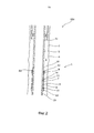
на фиг. 2 показан затрубный барьер, изображенный на фиг. 1, в неразжатом состоянии,in FIG. 2 shows the annular barrier of FIG. 1, in an uncompressed state,
на фиг. 3a - фиг. 3d показаны различные затрубные барьеры, содержащие устройство детектирования для детектирования ситуации, когда разжимная муфта разжата в положение контакта, иin FIG. 3a - FIG. 3d shows various annular barriers containing a detection device for detecting a situation where the expansion sleeve is unclenched to a contact position, and
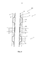
на фиг. 4 показана скважинная система, содержащая множество затрубных барьеров.in FIG. 4 shows a downhole system comprising a plurality of annular barriers.
Все чертежи являются схематичными, при этом они выполнены не обязательно в масштабе, причем на них показаны только те части, которые необходимы для объяснения изобретения, при этом другие части опущены или просто предполагаются.All drawings are schematic, but not necessarily to scale, and only those parts are shown that are necessary to explain the invention, while other parts are omitted or are simply intended.
Осуществление изобретенияThe implementation of the invention
На фиг. 1 показан затрубный барьер 1, который разжат в затрубном пространстве 2 между скважинной трубной конструкцией 3 и внутренней стенкой 4 ствола 5 скважины. Затрубный барьер 1 содержит трубную часть 6, которая установлена в качестве части скважинной трубной конструкции 3 посредством резьбового соединения 19. Затрубный барьер 1 содержит разжимную муфту 7, которая окружает трубную часть 6 и имеет наружную поверхность 8, примыкающую к внутренней стенке 4 ствола 5 скважины при разжатом состоянии затрубного барьера 1. Каждый конец 9 и 10 разжимной муфты 7 прикреплен к трубной части 6 посредством соединительной части 12. Разжимная муфта 7 окружает трубную часть 6, образуя полость 13 затрубного барьера. В трубной части 6 расположено отверстие 11, через которое текучая среда подается в полость 13 для разжимания муфты 7. При разжимании разжимной муфты 7 в скважинной трубной конструкции 3 создается избыточное давление посредством текучей среды из верхней части скважины, при этом данная текучая среда под давлением нагнетается в полость для разжимания разжимной муфты 7.In FIG. 1 shows the
Одна или обе соединительные части 12 могут скользить по отношению к трубной части 6, при этом другая часть может неподвижно соединяться с трубной частью 6. Скользящая соединительная часть 12 содержит уплотняющие элементы 60. Затрубные барьеры 1 также могут быть расположены для обеспечения уплотнения между двумя трубными конструкциями 3, например, между промежуточной обсадной колонной 18 и эксплуатационной обсадной колонной 31 вместо пакера 40 другого типа.One or both of the connecting
Затрубный барьер 1 дополнительно содержит запорный клапан 14, расположенный в отверстии 11. Запорный клапан имеет открытое и закрытое положения. В открытом положении текучая среда подается в полость 13, при этом в закрытом положении текущая среда больше не может проходить через запорный клапан 14 в полость 13. Благодаря наличию запорного клапана 14 отверстие 11 трубной части 6 затрубного барьера 1 может быть закрыто, когда разжимная муфта 7 разжата в положение контакта, как показано на фиг. 1.The
На фиг. 2 показан затрубный барьер 1 до его разжимания. Для разжимания одного или нескольких затрубных барьеров в трубной конструкции 3 создается избыточное давление посредством текучей среды. Как показано на фиг. 3a - фиг. 3d, для обеспечения возможности детектирования ситуации, когда разжимная муфта 7 разжата в положение контакта, как показано на фиг. 1, затрубный барьер 1 содержит устройство 20 детектирования, отслеживающее процесс разжимания. Устройство 20 детектирования выполнено с возможностью активации запорного клапана 14 для переключения запорного клапана 14 из открытого положения в закрытое положение при детектирования ситуации, когда разжимная муфта 7 разжата в положение контакта.In FIG. 2 shows the
Таким образом, устройство 20 детектирования, показанное на фиг. 3a-3d, содержит датчик 21 перемещения для детектирования перемещения скользящей муфты или перемещения разжимной муфты 7. Датчик 21 перемещения детектирует перемещение муфты 7 или скользящей соединительной части 12, что снова инициирует детектирование остановки перемещения и детектирование положения контакта, в котором достигнут контакт между внешней поверхностью 8 разжимной муфты 7 и внутренней стенкой ствола скважины. В положении контакта предотвращается дальнейшее радиальное разжимание разжимной муфты 7 и, таким образом, останавливается перемещение скользящей соединительной части 12 и муфты 7.Thus, the
В одном варианте осуществления изобретения датчик 20 детектирования содержит датчик 21 перемещения для детектирования перемещения одной соединительной части 12, скользящей по отношению к трубной части 6, или для детектирования перемещения обеих соединительных частей 12, скользящих по отношению к трубной части 6.In one embodiment of the invention, the
В варианте осуществления изобретения, показанном на фиг. 3a, в качестве датчика перемещения 21 используется линейный потенциометр 34, измеряющий положение скользящей соединительной части 12 в продольном направлении вдоль трубной части 6. Линейный потенциометр 34 содержит резистивный элемент 22 и очистительное устройство 23, выполненное с возможностью перемещения в продольном направлении резистивного элемента 22. В качестве линейного потенциометра может использоваться линейный мембранный потенциометр типа доступных линейных мембранных потенциометров фирмы Spectra Symbols. Как показано на фиг. 3а, очистительное устройство 23 расположено на одной из соединительных частей 12, выполненной с возможностью скольжения по отношению к трубной части 6. Очистительное устройство 23 примыкает к резистивному элементу 22, при этом путем измерения электрического выходного сигнала, например, напряжения на резистивном элементе 22 можно определить точное положение очистительного устройства 23 на резистивном элементе 22.In the embodiment shown in FIG. 3a, a
Как показано на фиг. 3b, в качестве датчика 21 перемещения может использоваться альтернативно датчик 24 расстояния, измеряющий расстояние между скользящей соединительной частью 12 и заданным положением 33 на трубной части 6. Датчик 24 расстояния может содержать лазер или любое другое средство, известное специалисту, подходящее для измерения расстояния между скользящей соединительной частью 12 и заданным положением 33. Посредством непрерывного измерения расстояния можно определить положение скользящей соединительной части, а также определить, перемещается ли соединительная часть.As shown in FIG. 3b, alternatively, a
Как показано на фиг. 3c, в качестве датчика 21 перемещения может также использоваться датчик переменного магнитного сопротивления, например, индуктивный магнитный датчик 26 для измерения положения скользящей соединительной части 12 в продольном направлении на трубной части 6. Индуктивный магнитный датчик детектирует множество магнитных элементов 25, встроенных на наружной поверхности трубной части. Чтобы детектировать перемещение скользящей соединительной части может быть отслежена частота детектирования магнитного элемента. Альтернативно может быть детектировано число магнитных элементов для определения положения соединительного элемента.As shown in FIG. 3c, a variable magnetic resistance sensor can also be used as a
Датчик 21 перемещения может также содержать следящее колесо (не показано), расположенное на скользящей соединительной части и приводимое в действие на наружной поверхности трубной части. Путем детектирования вращения следящего колеса можно определить, перемещается ли скользящая соединительная часть. Число оборотов также может использоваться для определения положения скользящей соединительной части 12.The
Датчик 21 перемещения непрерывно детектирует, перемещается ли скользящая соединительная часть и, возможно, также регистрирует положение в продольном направлении, чтобы определить полное смещение скользящей соединительной части 12. Таким образом, датчик 21 перемещения может использоваться для того, чтобы определить, когда остановилось перемещение скользящей соединительной части 12. Выходной сигнал от датчика 21 перемещения используется устройством 20 детектирования, чтобы определить, когда разжимная муфта 7 разжата в положение контакта и когда запорный клапан 14 должен быть активирован для блокирования потока текучей среды в полость 13.The
В другом варианте осуществления изобретения устройство 20 детектирования содержит датчик 29 разжимания для детектирования разжимания материала разжимной муфты 7. Датчик 29 разжимания может содержать тензометр 30 или любое другое средство, которые пригодно для измерения разжимания материала, расположенное на внешней поверхности 8 разжимной муфты 7.In another embodiment, the
В еще одном варианте осуществления изобретения устройство детектирования содержит датчик 21 перемещения и датчик 29 разжимания в соответствии с описанием, приведенным выше.In yet another embodiment of the invention, the detection device comprises a
В вариантах осуществления изобретения устройство детектирования может также содержать различные другие датчики, выполненные с возможностью детектирования ситуации, когда разжимная муфта 7 разжата в положение контакта. Как показано на фиг. 3c, затрубный барьер 1 содержит один или несколько датчиков 27 контактного давления, расположенных на внешней поверхности 8 разжимной муфты 7. Датчики 27 давления измеряют контактное давление между внешней поверхностью 8 разжимной муфты 7 и внутренней стенкой ствола скважины, когда затрубный барьер разжимается в скважине, как показано на фиг. 1. Как показано на фиг. 3d, устройство 20 детектирования может также содержать датчик 28 расстояния, выполненный с возможностью измерения внутреннего диаметра 36 разжатой муфты. Кроме того, как показано на фиг. 3c, для измерения давления внутри полости 13 может быть расположен датчик 35 давления текучей среды.In embodiments of the invention, the detection device may also include various other sensors configured to detect situations where the
Устройство 20 детектирования может исходить из одного или из нескольких детектируемых параметров, например, из перемещения скользящей соединительной части, разжимания материала разжимной муфты, внутреннего диаметра 36 разжатой муфты 7 и/или контактного давления или давления внутри разжимной муфты для того, чтобы определить, когда разжимная муфта разжата в положение контакта.The
Когда одна или несколько разжимных муфт 7 должны быть разжаты путем создания избыточного давления в трубной конструкции изнутри, устройство 20 детектирования детектирует ситуацию, когда останавливается скользящая соединительная часть, то есть когда достигается положение контакта и/или когда материал разжимной муфты больше не разжимается, когда достигнуто положение контакта. Когда скользящая соединительная часть 12 остановилась и/или когда материал разжимной муфты больше не разжимается, устройство 20 детектирования может определить, что разжимная муфта 7 достаточно разжата, чтобы обеспечить достаточный контакт между внешней поверхностью 8 разжимной муфты 7 и внутренней стенкой ствола скважины и, тем самым, разжата в положение контакта. Устройство 20 детектирования может также детектировать давление в полости 13 и ожидать некоторое увеличение давления до определения того, что разжимная муфта достаточно разжата.When one or more
Когда устройство 20 детектирования определяет, что разжимная муфта 7 достаточно разжата, что означает, что достигнуто положение контакта, устройство 20 детектирования вызывает закрывание запорного клапана 14 для предотвращения дальнейшего увеличения давления внутри полости 13, потому, что давление в скважине возрастает для разжимания других затрубных барьеров, что требует более высокого разжимного давления. В одном варианте осуществления изобретения запорный клапан 14 является соленоидным клапаном, который закрывается путем прекращения подачи электропитания, необходимого для удержания клапана открытым. Таким образом, когда разжимная муфта 7 достаточно разжата, подача электропитания на соленоидный клапан прекращается, в результате чего клапан 14 закрывается и полость 13 уплотняется. Если по какой-либо причине требуется, чтобы запорный клапан был снова открыт, например, для выравнивания давления между стволом скважины и полостью 13 внутри разжатой муфты, то это может быть выполнено путем возобновления подачи электропитания на соленоидный клапан. Выравнивание давления может требоваться в связи с операциями нагнетания, интенсификации или раздробления.When the
Устройство детектирования может дополнительно содержать таймер для закрытия запорного клапана 14 после заданного промежутка времени, следующего после детектирования разжимной муфты 7, находящейся в положении контакта, в котором предотвращается дальнейшее перемещение муфты и скользящей соединительной части. Благодаря таймеру закрытие клапана может происходить с определенной задержкой для обеспечения того, что муфта 7 полностью разжата так, что клапан 14 не закрывается слишком рано.The detection device may further comprise a timer for closing the shut-off
Устройство 20 детектирования может дополнительно содержать сейсмический датчик или акустический датчик другого типа для детектирования звука в отверстии 11, чтобы детектировать любые изменения звука во время разжимания. Проходящая в полость 13 текучая среда создает определенный звук, причем, когда достигается положения контакта и выполняется промежуточная остановка процесса разжимания перед продолжением и нежелательным разрушением формации, текучая среда больше не проходит в полость 13, вследствие чего звук соответственно уменьшается, что указывает на то, что положение контакта достигнуто.The
Изобретение относится, кроме того, к скважинной системе 100, содержащей множество затрубных барьеров 1, как показано на фиг. 4, в соответствии с тем, что описано выше. Скважинная система 100 содержит скважинную трубную конструкцию 3, имеющую клапанную секцию 50, расположенную между двумя затрубными барьерами для подачи углеводородосодержащей текучей среды в трубную конструкцию 3 скважины и наверх через эксплуатационную обсадную колонну 31. Клапанная секция 50 имеет впускные регулирующие клапаны 51 и отверстие разрыва пласта или клапан 52 разрыва пласта. Напротив клапанов в углублении на наружной поверхности скважинной трубной конструкции 3 может быть расположен экран 54. Напротив клапана 14 расположено множество скользящих или поворотных муфт 53 для закрытия клапана в то время, когда в скважинной трубной конструкции 3 создается избыточное давление.The invention further relates to a
Под положением контакта понимается положение разжатой муфты, в котором достигается контакт между внешней поверхностью 8 разжимной муфты 7 и внутренней стенкой 4 ствола скважины так, что затрубный барьер обеспечивает изоляцию одной части затрубного пространства от другой части затрубного пространства.Contact position refers to the position of the expanded coupling in which contact is achieved between the
Под текучей средой или скважинной текучей средой понимается текучая среда любого вида, которая может присутствовать в нефтяной или газовой скважине, например, природный газ, нефть, буровой раствор на нефтяной основе, сырая нефть, вода и т.д. Под газом понимается газ любого состава, присутствующий в скважине, в оборудованной скважине или в необсаженном стволе скважины, при этом под нефтью понимается нефть любого состава, например, сырая нефть, нефтесодержащая текучая среда и т.д. Газ, нефть, и водные текучие среды могут, таким образом, содержать элементы или вещества, отличные соответственно от газа, нефти, и/или воды.By fluid or borehole fluid is meant any kind of fluid that may be present in an oil or gas well, for example, natural gas, oil, oil-based drilling fluid, crude oil, water, etc. Gas is understood to be gas of any composition present in a well, in an equipped well or in an open-hole well, while oil is understood to mean oil of any composition, for example, crude oil, oily fluid, etc. Gas, oil, and aqueous fluids may thus contain elements or substances other than gas, oil, and / or water, respectively.
Под обсадной колонной понимается любой тип труб, насосно-компрессорных труб, обсадной трубы, колонны-хвостовика, трубной колонны и т.д., используемый в скважине при добыче нефти или природного газа.Casing string is any type of pipe, tubing, casing, liner, pipe string, etc. used in a well to produce oil or natural gas.
В случае если инструменты являются не погружаемыми по всей длине обсадную колонну, может использоваться скважинный трактор для продвижения инструментов по всей длине в положение в скважине. Скважинный трактор представляет собой приводной инструмент любого типа, выполненный с возможностью продвижения или протягивания инструментов в скважине, например, Well Tractor ®.If the tools are not submersible along the entire length of the casing, a downhole tractor can be used to advance the tools along the entire length to a position in the well. A downhole tractor is a power tool of any type, configured to advance or extend tools in a well, such as Well Tractor ®.
Хотя изобретение описано выше в связи с предпочтительными вариантами осуществления изобретения, специалисту в данной области техники очевидно, что можно выполнить некоторые модификации без отхода от сути изобретения, определенной в прилагаемой формуле изобретения.Although the invention has been described above in connection with preferred embodiments of the invention, it will be apparent to those skilled in the art that some modifications can be made without departing from the spirit of the invention defined in the appended claims.
Claims (24)
Applications Claiming Priority (3)
| Application Number | Priority Date | Filing Date | Title |
|---|---|---|---|
| EP11194957.4 | 2011-12-21 | ||
| EP11194957.4A EP2607614B1 (en) | 2011-12-21 | 2011-12-21 | An annular barrier with an expansion detection device |
| PCT/EP2012/076285 WO2013092801A1 (en) | 2011-12-21 | 2012-12-20 | An annular barrier with an expansion detection device |
Publications (2)
| Publication Number | Publication Date |
|---|---|
| RU2014126731A RU2014126731A (en) | 2016-02-10 |
| RU2606474C2 true RU2606474C2 (en) | 2017-01-10 |
Family
ID=47428644
Family Applications (1)
| Application Number | Title | Priority Date | Filing Date |
|---|---|---|---|
| RU2014126731A RU2606474C2 (en) | 2011-12-21 | 2012-12-20 | Annular barrier with expansion detection device |
Country Status (11)
| Country | Link |
|---|---|
| US (1) | US9366107B2 (en) |
| EP (1) | EP2607614B1 (en) |
| CN (1) | CN103975122B (en) |
| AU (1) | AU2012357077B2 (en) |
| BR (1) | BR112014013584A8 (en) |
| CA (1) | CA2858472C (en) |
| DK (1) | DK2607614T3 (en) |
| MX (1) | MX345360B (en) |
| MY (1) | MY174893A (en) |
| RU (1) | RU2606474C2 (en) |
| WO (1) | WO2013092801A1 (en) |
Families Citing this family (17)
| Publication number | Priority date | Publication date | Assignee | Title |
|---|---|---|---|---|
| US9920620B2 (en) | 2014-03-24 | 2018-03-20 | Halliburton Energy Services, Inc. | Well tools having magnetic shielding for magnetic sensor |
| MY177417A (en) | 2014-05-09 | 2020-09-15 | Welltec Oilfield Solutions Ag | Downhole completion system |
| EP2947259A1 (en) | 2014-05-19 | 2015-11-25 | Welltec A/S | Downhole string for drilling through a low pressure zone |
| GB2526596B (en) | 2014-05-29 | 2020-10-07 | Schlumberger B V | Morphable apparatus |
| EP3088654A1 (en) * | 2015-04-30 | 2016-11-02 | Welltec A/S | Annular barrier with expansion unit |
| EP3255240A1 (en) * | 2016-06-10 | 2017-12-13 | Welltec A/S | Downhole straddle system |
| EP3327246A1 (en) * | 2016-11-25 | 2018-05-30 | Welltec A/S | Annular barrier with expansion verification |
| EP3415711A1 (en) * | 2017-06-13 | 2018-12-19 | Welltec A/S | Downhole patch setting tool |
| US11142988B2 (en) * | 2017-09-29 | 2021-10-12 | Schlumberger Technology Corporation | Stress testing with inflatable packer assembly |
| CN109751008B (en) * | 2017-11-01 | 2021-01-05 | 中国石油化工股份有限公司 | Pipe string |
| US10746014B2 (en) * | 2018-02-09 | 2020-08-18 | Schlumberger Technology Corporation | Method and system for monitoring a condition of an elastic element used in a downhole tool |
| GB2572449B (en) * | 2018-03-30 | 2020-09-16 | Morphpackers Ltd | Improved isolation barrier |
| CN113272516A (en) * | 2019-01-08 | 2021-08-17 | 韦尔泰克油田解决方案股份公司 | Downhole method |
| US11061084B2 (en) | 2019-03-07 | 2021-07-13 | Allegro Microsystems, Llc | Coil actuated pressure sensor and deflectable substrate |
| US10955306B2 (en) * | 2019-04-22 | 2021-03-23 | Allegro Microsystems, Llc | Coil actuated pressure sensor and deformable substrate |
| GB202108414D0 (en) * | 2021-06-12 | 2021-07-28 | Morphpackers Ltd | High expandable straddle annular isolation system |
| CN115013529A (en) * | 2022-06-24 | 2022-09-06 | 衡橡科技股份有限公司 | Y-shaped packer |
Citations (6)
| Publication number | Priority date | Publication date | Assignee | Title |
|---|---|---|---|---|
| US5353637A (en) * | 1992-06-09 | 1994-10-11 | Plumb Richard A | Methods and apparatus for borehole measurement of formation stress |
| RU6406U1 (en) * | 1995-04-19 | 1998-04-16 | Клявин Рим Мусеевич | PACKING DEVICE |
| RU2173379C2 (en) * | 1999-09-06 | 2001-09-10 | Волго-уральский центр научно-технических услуг "НЕЙТРОН" | Electrohydromechanical device with remote control for packer setting in oil and gas wells and method of hydrodynamic researches of these wells |
| RU2285111C1 (en) * | 2005-04-05 | 2006-10-10 | ОАО "Татнефть" им. В.Д. Шашина | Pressure testing device to determine well string fluid influx in well string |
| RU2305748C1 (en) * | 2006-01-10 | 2007-09-10 | Олег Марсович Гарипов | Packer |
| RU2391502C2 (en) * | 2005-09-01 | 2010-06-10 | Шлюмбергер Текнолоджи Б.В. | Methods, systems and device for test on flexible tubing string |
Family Cites Families (18)
| Publication number | Priority date | Publication date | Assignee | Title |
|---|---|---|---|---|
| US3926254A (en) * | 1974-12-20 | 1975-12-16 | Halliburton Co | Down-hole pump and inflatable packer apparatus |
| US4230180A (en) * | 1978-11-13 | 1980-10-28 | Westbay Instruments Ltd. | Isolating packer units in geological and geophysical measuring casings |
| US4421165A (en) * | 1980-07-15 | 1983-12-20 | Halliburton Company | Multiple stage cementer and casing inflation packer |
| US4899320A (en) * | 1985-07-05 | 1990-02-06 | Atlantic Richfield Company | Downhole tool for determining in-situ formation stress orientation |
| US4869110A (en) * | 1988-06-16 | 1989-09-26 | Systems Integration Technology, Inc. | Laser strain extensometer for material testing |
| US5277253A (en) * | 1992-04-03 | 1994-01-11 | Halliburton Company | Hydraulic set casing packer |
| US5291947A (en) * | 1992-06-08 | 1994-03-08 | Atlantic Richfield Company | Tubing conveyed wellbore straddle packer system |
| US5778982A (en) * | 1993-10-27 | 1998-07-14 | Baski Water Instruments, Inc. | Fixed head inflatable packer with fully reinforced inflatable element and method of fabrication |
| WO1998009163A1 (en) * | 1996-08-26 | 1998-03-05 | Baker Hughes Incorporated | Method for verifying positive inflation of an inflatable element |
| GB9902436D0 (en) * | 1999-02-04 | 1999-03-24 | Solinst Canada Ltd | Double acting packer |
| US7322422B2 (en) * | 2002-04-17 | 2008-01-29 | Schlumberger Technology Corporation | Inflatable packer inside an expandable packer and method |
| US6854522B2 (en) * | 2002-09-23 | 2005-02-15 | Halliburton Energy Services, Inc. | Annular isolators for expandable tubulars in wellbores |
| US20040173363A1 (en) * | 2003-03-04 | 2004-09-09 | Juan Navarro-Sorroche | Packer with integrated sensors |
| US7367393B2 (en) * | 2004-06-01 | 2008-05-06 | Baker Hughes Incorporated | Pressure monitoring of control lines for tool position feedback |
| EP2254724B1 (en) * | 2008-03-11 | 2018-06-13 | Frank's International, LLC | Laser shock peening |
| US8091634B2 (en) * | 2008-11-20 | 2012-01-10 | Schlumberger Technology Corporation | Single packer structure with sensors |
| EP2206879B1 (en) * | 2009-01-12 | 2014-02-26 | Welltec A/S | Annular barrier and annular barrier system |
| US9175549B2 (en) * | 2011-06-06 | 2015-11-03 | Sumathi Paturu | Emergency salvage of a crumbled oceanic oil well |
-
2011
- 2011-12-21 EP EP11194957.4A patent/EP2607614B1/en not_active Not-in-force
- 2011-12-21 DK DK11194957.4T patent/DK2607614T3/en active
-
2012
- 2012-12-20 WO PCT/EP2012/076285 patent/WO2013092801A1/en active Application Filing
- 2012-12-20 MY MYPI2014001617A patent/MY174893A/en unknown
- 2012-12-20 US US14/362,906 patent/US9366107B2/en not_active Expired - Fee Related
- 2012-12-20 MX MX2014006798A patent/MX345360B/en active IP Right Grant
- 2012-12-20 CN CN201280060274.9A patent/CN103975122B/en not_active Expired - Fee Related
- 2012-12-20 CA CA2858472A patent/CA2858472C/en not_active Expired - Fee Related
- 2012-12-20 AU AU2012357077A patent/AU2012357077B2/en not_active Ceased
- 2012-12-20 BR BR112014013584A patent/BR112014013584A8/en active Search and Examination
- 2012-12-20 RU RU2014126731A patent/RU2606474C2/en active
Patent Citations (6)
| Publication number | Priority date | Publication date | Assignee | Title |
|---|---|---|---|---|
| US5353637A (en) * | 1992-06-09 | 1994-10-11 | Plumb Richard A | Methods and apparatus for borehole measurement of formation stress |
| RU6406U1 (en) * | 1995-04-19 | 1998-04-16 | Клявин Рим Мусеевич | PACKING DEVICE |
| RU2173379C2 (en) * | 1999-09-06 | 2001-09-10 | Волго-уральский центр научно-технических услуг "НЕЙТРОН" | Electrohydromechanical device with remote control for packer setting in oil and gas wells and method of hydrodynamic researches of these wells |
| RU2285111C1 (en) * | 2005-04-05 | 2006-10-10 | ОАО "Татнефть" им. В.Д. Шашина | Pressure testing device to determine well string fluid influx in well string |
| RU2391502C2 (en) * | 2005-09-01 | 2010-06-10 | Шлюмбергер Текнолоджи Б.В. | Methods, systems and device for test on flexible tubing string |
| RU2305748C1 (en) * | 2006-01-10 | 2007-09-10 | Олег Марсович Гарипов | Packer |
Also Published As
| Publication number | Publication date |
|---|---|
| CN103975122B (en) | 2016-12-14 |
| CA2858472A1 (en) | 2013-06-27 |
| MX2014006798A (en) | 2014-07-09 |
| EP2607614A1 (en) | 2013-06-26 |
| DK2607614T3 (en) | 2015-02-02 |
| AU2012357077B2 (en) | 2015-08-20 |
| BR112014013584A2 (en) | 2017-06-13 |
| US20140332232A1 (en) | 2014-11-13 |
| RU2014126731A (en) | 2016-02-10 |
| CN103975122A (en) | 2014-08-06 |
| WO2013092801A1 (en) | 2013-06-27 |
| BR112014013584A8 (en) | 2017-06-13 |
| EP2607614B1 (en) | 2014-10-15 |
| MY174893A (en) | 2020-05-20 |
| US9366107B2 (en) | 2016-06-14 |
| CA2858472C (en) | 2020-10-06 |
| MX345360B (en) | 2017-01-25 |
| AU2012357077A1 (en) | 2014-07-17 |
Similar Documents
| Publication | Publication Date | Title |
|---|---|---|
| RU2606474C2 (en) | Annular barrier with expansion detection device | |
| US6041864A (en) | Well isolation system | |
| US6736213B2 (en) | Method and system for controlling a downhole flow control device using derived feedback control | |
| CA2519325C (en) | Methods and apparatus for expanding tubular strings and isolating subterranean zones | |
| NO20161887A1 (en) | APPARATUS AND METHOD FOR OPERATING A DEVICE IN A WELLBORE USING SIGNALS GENERATED IN RESPONSE TO STRAIN ON A DOWNHOLE MEMBER | |
| US10753169B2 (en) | Intelligent pressure control devices and methods of use thereof | |
| WO2016024088A1 (en) | Apparatus and method of connecting tubular members in multi-lateral wellbores | |
| CN110621844A (en) | Sensor system for blowout preventer and method of using the same | |
| US20150233209A1 (en) | Control line damper for valves | |
| GB2463588A (en) | Tags or markers prompt expansion of tubulars | |
| CA2622596C (en) | Methods and apparatus for expanding tubular strings and isolating subterranean zones | |
| US20140076446A1 (en) | Fluid flow impedance system | |
| CA2740457C (en) | Hydraulic set packer system and fracturing methods | |
| AU2019454261B2 (en) | Multiple port opening method with single pressure activation | |
| US11313190B2 (en) | Electric set tieback anchor via pressure cycles | |
| US20210054718A1 (en) | Pumpdown Regulator | |
| AU2012384917B2 (en) | Control line damper for valves | |
| WO2023121895A1 (en) | Intelligent section mill, method, and system |
Legal Events
| Date | Code | Title | Description |
|---|---|---|---|
| PC41 | Official registration of the transfer of exclusive right |
Effective date: 20190312 |
|
| PD4A | Correction of name of patent owner |