RU2605981C2 - Method of wind-driven electric plant concrete tower segment making - Google Patents
Method of wind-driven electric plant concrete tower segment making Download PDFInfo
- Publication number
- RU2605981C2 RU2605981C2 RU2014101772A RU2014101772A RU2605981C2 RU 2605981 C2 RU2605981 C2 RU 2605981C2 RU 2014101772 A RU2014101772 A RU 2014101772A RU 2014101772 A RU2014101772 A RU 2014101772A RU 2605981 C2 RU2605981 C2 RU 2605981C2
- Authority
- RU
- Russia
- Prior art keywords
- tower
- segment
- concrete
- formwork
- tower segment
- Prior art date
Links
- 239000004567 concrete Substances 0.000 title claims abstract description 142
- 238000000034 method Methods 0.000 title claims abstract description 26
- 238000009415 formwork Methods 0.000 claims abstract description 162
- 238000004519 manufacturing process Methods 0.000 claims abstract description 56
- 238000009434 installation Methods 0.000 claims description 22
- 238000005259 measurement Methods 0.000 claims description 12
- 238000012545 processing Methods 0.000 claims description 8
- 238000012937 correction Methods 0.000 claims description 3
- 238000010276 construction Methods 0.000 abstract description 23
- 238000002360 preparation method Methods 0.000 abstract 1
- 239000000126 substance Substances 0.000 abstract 1
- 230000006870 function Effects 0.000 description 13
- 238000000926 separation method Methods 0.000 description 13
- 230000033001 locomotion Effects 0.000 description 10
- 229910000831 Steel Inorganic materials 0.000 description 5
- 239000010959 steel Substances 0.000 description 5
- 238000005266 casting Methods 0.000 description 4
- 239000003795 chemical substances by application Substances 0.000 description 3
- 230000006872 improvement Effects 0.000 description 3
- 230000009471 action Effects 0.000 description 2
- 230000007423 decrease Effects 0.000 description 2
- 239000007788 liquid Substances 0.000 description 2
- 239000000463 material Substances 0.000 description 2
- 239000002184 metal Substances 0.000 description 2
- 230000008520 organization Effects 0.000 description 2
- 239000004033 plastic Substances 0.000 description 2
- 239000011150 reinforced concrete Substances 0.000 description 2
- 230000002787 reinforcement Effects 0.000 description 2
- 230000007704 transition Effects 0.000 description 2
- 108091027981 Response element Proteins 0.000 description 1
- 239000000853 adhesive Substances 0.000 description 1
- 230000001070 adhesive effect Effects 0.000 description 1
- 230000008901 benefit Effects 0.000 description 1
- 230000005540 biological transmission Effects 0.000 description 1
- 230000015572 biosynthetic process Effects 0.000 description 1
- 230000006835 compression Effects 0.000 description 1
- 238000007906 compression Methods 0.000 description 1
- 230000008094 contradictory effect Effects 0.000 description 1
- 230000002950 deficient Effects 0.000 description 1
- 238000013461 design Methods 0.000 description 1
- 238000005553 drilling Methods 0.000 description 1
- 230000005484 gravity Effects 0.000 description 1
- 239000011796 hollow space material Substances 0.000 description 1
- 238000009776 industrial production Methods 0.000 description 1
- 230000013011 mating Effects 0.000 description 1
- 238000000691 measurement method Methods 0.000 description 1
- 239000002991 molded plastic Substances 0.000 description 1
- 238000012544 monitoring process Methods 0.000 description 1
- 230000008447 perception Effects 0.000 description 1
- 238000003825 pressing Methods 0.000 description 1
- 230000008569 process Effects 0.000 description 1
- 239000007787 solid Substances 0.000 description 1
- 238000007711 solidification Methods 0.000 description 1
- 230000008023 solidification Effects 0.000 description 1
Images


Classifications
-
- B—PERFORMING OPERATIONS; TRANSPORTING
- B28—WORKING CEMENT, CLAY, OR STONE
- B28B—SHAPING CLAY OR OTHER CERAMIC COMPOSITIONS; SHAPING SLAG; SHAPING MIXTURES CONTAINING CEMENTITIOUS MATERIAL, e.g. PLASTER
- B28B7/00—Moulds; Cores; Mandrels
- B28B7/02—Moulds with adjustable parts specially for modifying at will the dimensions or form of the moulded article
-
- B—PERFORMING OPERATIONS; TRANSPORTING
- B28—WORKING CEMENT, CLAY, OR STONE
- B28B—SHAPING CLAY OR OTHER CERAMIC COMPOSITIONS; SHAPING SLAG; SHAPING MIXTURES CONTAINING CEMENTITIOUS MATERIAL, e.g. PLASTER
- B28B17/00—Details of, or accessories for, apparatus for shaping the material; Auxiliary measures taken in connection with such shaping
- B28B17/0063—Control arrangements
- B28B17/0072—Product control or inspection
-
- B—PERFORMING OPERATIONS; TRANSPORTING
- B28—WORKING CEMENT, CLAY, OR STONE
- B28B—SHAPING CLAY OR OTHER CERAMIC COMPOSITIONS; SHAPING SLAG; SHAPING MIXTURES CONTAINING CEMENTITIOUS MATERIAL, e.g. PLASTER
- B28B21/00—Methods or machines specially adapted for the production of tubular articles
- B28B21/02—Methods or machines specially adapted for the production of tubular articles by casting into moulds
-
- B—PERFORMING OPERATIONS; TRANSPORTING
- B28—WORKING CEMENT, CLAY, OR STONE
- B28B—SHAPING CLAY OR OTHER CERAMIC COMPOSITIONS; SHAPING SLAG; SHAPING MIXTURES CONTAINING CEMENTITIOUS MATERIAL, e.g. PLASTER
- B28B21/00—Methods or machines specially adapted for the production of tubular articles
- B28B21/76—Moulds
- B28B21/82—Moulds built-up from several parts; Multiple moulds; Moulds with adjustable parts
-
- B—PERFORMING OPERATIONS; TRANSPORTING
- B28—WORKING CEMENT, CLAY, OR STONE
- B28B—SHAPING CLAY OR OTHER CERAMIC COMPOSITIONS; SHAPING SLAG; SHAPING MIXTURES CONTAINING CEMENTITIOUS MATERIAL, e.g. PLASTER
- B28B23/00—Arrangements specially adapted for the production of shaped articles with elements wholly or partly embedded in the moulding material; Production of reinforced objects
- B28B23/005—Arrangements specially adapted for the production of shaped articles with elements wholly or partly embedded in the moulding material; Production of reinforced objects with anchoring or fastening elements for the shaped articles
-
- B—PERFORMING OPERATIONS; TRANSPORTING
- B28—WORKING CEMENT, CLAY, OR STONE
- B28B—SHAPING CLAY OR OTHER CERAMIC COMPOSITIONS; SHAPING SLAG; SHAPING MIXTURES CONTAINING CEMENTITIOUS MATERIAL, e.g. PLASTER
- B28B7/00—Moulds; Cores; Mandrels
- B28B7/0029—Moulds or moulding surfaces not covered by B28B7/0058 - B28B7/36 and B28B7/40 - B28B7/465, e.g. moulds assembled from several parts
- B28B7/0035—Moulds characterised by the way in which the sidewalls of the mould and the moulded article move with respect to each other during demoulding
-
- B—PERFORMING OPERATIONS; TRANSPORTING
- B28—WORKING CEMENT, CLAY, OR STONE
- B28B—SHAPING CLAY OR OTHER CERAMIC COMPOSITIONS; SHAPING SLAG; SHAPING MIXTURES CONTAINING CEMENTITIOUS MATERIAL, e.g. PLASTER
- B28B7/00—Moulds; Cores; Mandrels
- B28B7/22—Moulds for making units for prefabricated buildings, i.e. units each comprising an important section of at least two limiting planes of a room or space, e.g. cells; Moulds for making prefabricated stair units
-
- E—FIXED CONSTRUCTIONS
- E04—BUILDING
- E04B—GENERAL BUILDING CONSTRUCTIONS; WALLS, e.g. PARTITIONS; ROOFS; FLOORS; CEILINGS; INSULATION OR OTHER PROTECTION OF BUILDINGS
- E04B1/00—Constructions in general; Structures which are not restricted either to walls, e.g. partitions, or floors or ceilings or roofs
- E04B1/343—Structures characterised by movable, separable, or collapsible parts, e.g. for transport
- E04B1/34315—Structures characterised by movable, separable, or collapsible parts, e.g. for transport characterised by separable parts
- E04B1/34331—Structures characterised by movable, separable, or collapsible parts, e.g. for transport characterised by separable parts mainly constituted by three-dimensional elements
-
- E—FIXED CONSTRUCTIONS
- E04—BUILDING
- E04B—GENERAL BUILDING CONSTRUCTIONS; WALLS, e.g. PARTITIONS; ROOFS; FLOORS; CEILINGS; INSULATION OR OTHER PROTECTION OF BUILDINGS
- E04B1/00—Constructions in general; Structures which are not restricted either to walls, e.g. partitions, or floors or ceilings or roofs
- E04B1/343—Structures characterised by movable, separable, or collapsible parts, e.g. for transport
- E04B1/34336—Structures movable as a whole, e.g. mobile home structures
- E04B1/34347—Anchoring means therefor
-
- E—FIXED CONSTRUCTIONS
- E04—BUILDING
- E04G—SCAFFOLDING; FORMS; SHUTTERING; BUILDING IMPLEMENTS OR AIDS, OR THEIR USE; HANDLING BUILDING MATERIALS ON THE SITE; REPAIRING, BREAKING-UP OR OTHER WORK ON EXISTING BUILDINGS
- E04G13/00—Falsework, forms, or shutterings for particular parts of buildings, e.g. stairs, steps, cornices, balconies foundations, sills
- E04G13/02—Falsework, forms, or shutterings for particular parts of buildings, e.g. stairs, steps, cornices, balconies foundations, sills for columns or like pillars; Special tying or clamping means therefor
-
- E—FIXED CONSTRUCTIONS
- E04—BUILDING
- E04H—BUILDINGS OR LIKE STRUCTURES FOR PARTICULAR PURPOSES; SWIMMING OR SPLASH BATHS OR POOLS; MASTS; FENCING; TENTS OR CANOPIES, IN GENERAL
- E04H12/00—Towers; Masts or poles; Chimney stacks; Water-towers; Methods of erecting such structures
- E04H12/02—Structures made of specified materials
- E04H12/12—Structures made of specified materials of concrete or other stone-like material, with or without internal or external reinforcements, e.g. with metal coverings, with permanent form elements
-
- E—FIXED CONSTRUCTIONS
- E04—BUILDING
- E04H—BUILDINGS OR LIKE STRUCTURES FOR PARTICULAR PURPOSES; SWIMMING OR SPLASH BATHS OR POOLS; MASTS; FENCING; TENTS OR CANOPIES, IN GENERAL
- E04H12/00—Towers; Masts or poles; Chimney stacks; Water-towers; Methods of erecting such structures
- E04H12/16—Prestressed structures
-
- E—FIXED CONSTRUCTIONS
- E04—BUILDING
- E04H—BUILDINGS OR LIKE STRUCTURES FOR PARTICULAR PURPOSES; SWIMMING OR SPLASH BATHS OR POOLS; MASTS; FENCING; TENTS OR CANOPIES, IN GENERAL
- E04H12/00—Towers; Masts or poles; Chimney stacks; Water-towers; Methods of erecting such structures
- E04H12/34—Arrangements for erecting or lowering towers, masts, poles, chimney stacks, or the like
- E04H12/341—Arrangements for casting in situ concrete towers or the like
-
- E—FIXED CONSTRUCTIONS
- E04—BUILDING
- E04H—BUILDINGS OR LIKE STRUCTURES FOR PARTICULAR PURPOSES; SWIMMING OR SPLASH BATHS OR POOLS; MASTS; FENCING; TENTS OR CANOPIES, IN GENERAL
- E04H12/00—Towers; Masts or poles; Chimney stacks; Water-towers; Methods of erecting such structures
- E04H12/34—Arrangements for erecting or lowering towers, masts, poles, chimney stacks, or the like
- E04H12/342—Arrangements for stacking tower sections on top of each other
-
- G—PHYSICS
- G01—MEASURING; TESTING
- G01B—MEASURING LENGTH, THICKNESS OR SIMILAR LINEAR DIMENSIONS; MEASURING ANGLES; MEASURING AREAS; MEASURING IRREGULARITIES OF SURFACES OR CONTOURS
- G01B11/00—Measuring arrangements characterised by the use of optical techniques
- G01B11/24—Measuring arrangements characterised by the use of optical techniques for measuring contours or curvatures
-
- E—FIXED CONSTRUCTIONS
- E04—BUILDING
- E04H—BUILDINGS OR LIKE STRUCTURES FOR PARTICULAR PURPOSES; SWIMMING OR SPLASH BATHS OR POOLS; MASTS; FENCING; TENTS OR CANOPIES, IN GENERAL
- E04H12/00—Towers; Masts or poles; Chimney stacks; Water-towers; Methods of erecting such structures
- E04H2012/006—Structures with truss-like sections combined with tubular-like sections
-
- Y—GENERAL TAGGING OF NEW TECHNOLOGICAL DEVELOPMENTS; GENERAL TAGGING OF CROSS-SECTIONAL TECHNOLOGIES SPANNING OVER SEVERAL SECTIONS OF THE IPC; TECHNICAL SUBJECTS COVERED BY FORMER USPC CROSS-REFERENCE ART COLLECTIONS [XRACs] AND DIGESTS
- Y02—TECHNOLOGIES OR APPLICATIONS FOR MITIGATION OR ADAPTATION AGAINST CLIMATE CHANGE
- Y02E—REDUCTION OF GREENHOUSE GAS [GHG] EMISSIONS, RELATED TO ENERGY GENERATION, TRANSMISSION OR DISTRIBUTION
- Y02E10/00—Energy generation through renewable energy sources
- Y02E10/70—Wind energy
- Y02E10/72—Wind turbines with rotation axis in wind direction
-
- Y—GENERAL TAGGING OF NEW TECHNOLOGICAL DEVELOPMENTS; GENERAL TAGGING OF CROSS-SECTIONAL TECHNOLOGIES SPANNING OVER SEVERAL SECTIONS OF THE IPC; TECHNICAL SUBJECTS COVERED BY FORMER USPC CROSS-REFERENCE ART COLLECTIONS [XRACs] AND DIGESTS
- Y02—TECHNOLOGIES OR APPLICATIONS FOR MITIGATION OR ADAPTATION AGAINST CLIMATE CHANGE
- Y02P—CLIMATE CHANGE MITIGATION TECHNOLOGIES IN THE PRODUCTION OR PROCESSING OF GOODS
- Y02P70/00—Climate change mitigation technologies in the production process for final industrial or consumer products
- Y02P70/50—Manufacturing or production processes characterised by the final manufactured product
Abstract
Description
Данное изобретение относится к способу изготовления сегмента бетонной башни ветроэнергетической установки, а также к опалубке для изготовления такого сегмента башни. Кроме того, данное изобретение относится к производственному устройству для изготовления такого сегмента башни. Дополнительно к этому данное изобретение относится к бетонной башне из сегментов башни, а также к ветроэнергетической установке с такой бетонной башней. Кроме того, данное изобретение относится к группе бетонных башен, которая содержит по меньшей мере две различные бетонные башни, и изобретение относится к ветровому парку с такой группой бетонных башен. Кроме того, данное изобретение относится к способу возведения бетонных башен ветроэнергетических установок. Изобретение относится также к крепежному анкеру для фиксации сегмента башни подлежащей возведению бетонной башни ветроэнергетической установки при транспортировке на низкорамном прицепе. Кроме того, данное изобретение относится к фиксирующему устройству для фиксации сегмента башни подлежащей возведению бетонной башни ветроэнергетической установки при транспортировке на низкорамном прицепе. Кроме того, данное изобретение относится к устройству для измерения указанного сегмента башни.This invention relates to a method for manufacturing a segment of a concrete tower of a wind power installation, as well as to formwork for the manufacture of such a segment of the tower. In addition, this invention relates to a manufacturing device for manufacturing such a tower segment. In addition, this invention relates to a concrete tower of tower segments, as well as to a wind power installation with such a concrete tower. In addition, this invention relates to a group of concrete towers, which contains at least two different concrete towers, and the invention relates to a wind park with such a group of concrete towers. In addition, this invention relates to a method for erecting concrete towers of wind power plants. The invention also relates to a fixing anchor for fixing a tower segment of a concrete tower of a wind power plant to be erected during transportation on a low loader trailer. In addition, the present invention relates to a fixing device for fixing a tower segment of a concrete tower of a wind power plant to be erected during transportation on a low loader trailer. In addition, the present invention relates to a device for measuring said tower segment.
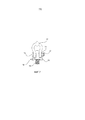
Ветроэнергетические установки, в частности, с горизонтальной осью ротора, как показано на фиг.1, находят в настоящее время широкое применение.Wind power plants, in particular with a horizontal axis of the rotor, as shown in figure 1, are currently widely used.
Такие ветроэнергетические установки имеют гондолу с аэродинамическим ротором. Эта гондола с ротором может иметь в зависимости от величины установки массу намного больше 100 т. Гондола опирается на башню, которая может быть выполнена в виде бетонной башни или стальной башни и принимать нагрузку гондолы и отводить ее в фундамент. Эта нагрузка содержит нагрузку за счет веса гондолы, а также нагрузку ветрового давления на ротор при работе ветроэнергетической установки.Such wind turbines have a nacelle with an aerodynamic rotor. This gondola with a rotor can have a mass of much more than 100 tons depending on the size of the installation. The gondola is based on a tower, which can be made in the form of a concrete tower or steel tower and take the load of the gondola and take it to the foundation. This load contains the load due to the weight of the nacelle, as well as the load of the wind pressure on the rotor during operation of the wind power installation.
Бетонные башни ветроэнергетических установок, из которых исходит данное изобретение, возводят из сегментов башни, а именно готовых конструктивных элементов из железобетона. Тем самым они принципиально отличаются от бетонных башен, которые возводят из так называемого монолитного бетона, т.е. непосредственно на месте с помощью скользящей опалубки, что обычно используется, например, для телевизионных башен. К бетонной башне ветроэнергетической установки предъявляются также совсем другие требования, чем к другой бетонной башне. Одним из специальных требований является уже указанная ветровая нагрузка ротора и тем самым гондолы и головной части башни.The concrete towers of the wind power plants from which this invention is based are erected from tower segments, namely, prefabricated structural elements from reinforced concrete. Thus, they are fundamentally different from concrete towers, which are built from the so-called monolithic concrete, i.e. directly in place using sliding formwork, which is usually used, for example, for television towers. The concrete tower of the wind power installation also has completely different requirements than the other concrete tower. One of the special requirements is the already indicated wind load of the rotor and thereby the nacelle and the head of the tower.
Согласно форме ветроэнергетической установки, башня проходит конически снизу от своего фундамента вверх к своей головной части. Для этого подлежащие установке друг на друга сегменты башни необходимо, соответственно, согласовывать друг с другом в местах стыковки. Это относится, в частности, к форме и диаметру соответствующих сегментов в зоне, в которой они устанавливаются друг на друга. Если отклонение двух подлежащих установке друг на друга сегментов здесь слишком велико, то соответствующая бетонная башня не может быть изготовлена с достаточным производственным качеством. В этом случае по меньшей мере один из подлежащих соединению друг с другом сегментов башни необходимо отбраковывать и заменять другим сегментом с лучшими, в частности, более точно выдерживаемыми размерами. По меньшей мере одну применяемую для изготовления бракованного сегмента башни опалубку необходимо, соответственно, изменять или заменять. Отбраковка такого непригодного сегмента башни, а также при необходимости замена применяемой опалубки приводит к ненужным затратам и может приводить к задержке возведения ветроэнергетической установки.According to the shape of the wind power installation, the tower runs conically from the bottom of its foundation up to its head. To do this, the segments of the tower to be installed on each other must, accordingly, be coordinated with each other at the joints. This applies in particular to the shape and diameter of the respective segments in the area in which they are mounted on top of each other. If the deviation of the two segments to be mounted on each other is too large here, then the corresponding concrete tower cannot be manufactured with sufficient production quality. In this case, at least one of the tower segments to be connected to each other must be rejected and replaced with another segment with better, in particular, more accurately maintained sizes. At least one formwork used for the manufacture of a defective tower segment must be changed or replaced accordingly. The rejection of such an unsuitable segment of the tower, as well as the replacement of the formwork used, if necessary, leads to unnecessary costs and may delay the construction of the wind power installation.
Для конически сужающейся башни ветроэнергетической установки, которая составлена из множества сегментов башни, а именно готовых бетонных частей, требуется, соответственно, большое количество различных сегментов башни. Для этих различных сегментов башни требуется, соответственно, много опалубок, т.е. форм для литья соответствующего конкретного сегмента башни. Если изготавливаются ветроэнергетические установки различной величины, то требуются, соответственно, различно большие бетонные башни, и, соответственно, увеличивается количество требуемых сегментов башни и необходимых опалубок. В частности, при становящихся все больше башнях и становящемся все больше количестве различных башен сильно увеличивается, соответственно, количество различных сегментов башни и необходимых опалубок, что может приводить к проблемам логистики и/или организации в соответствующем предприятии по изготовлению сегментов башни. По меньшей мере значительно увеличиваются затраты на логистику и организацию.For a conically tapering tower of a wind power installation, which is composed of many segments of the tower, namely the finished concrete parts, respectively, a large number of different segments of the tower are required. For these various tower segments, accordingly, many formwork is required, i.e. molds for the respective concrete tower segment. If wind power plants of various sizes are manufactured, differently large concrete towers are required, respectively, and, accordingly, the number of required tower segments and required formwork increases. In particular, with more and more towers and more and more different towers, the number of different tower segments and necessary formwork increases significantly, which can lead to problems in logistics and / or organization of a tower segment in the corresponding enterprise. At least significantly increased costs for logistics and organization.
Для изготовления частей бетонной башни, т.е. сегментов башни, а именно готовых бетонных частей, используются бетонные опалубки, которые образуют полое пространство, в которое заливают бетон. В них предусмотрена также соответствующая арматура, и после затвердевания бетона сегмент отделяют от опалубки, а затем подвергают соответствующей дальнейшей обработке. Для изготовления имеющих форму боковой поверхности усеченного конуса сегментов башни или соответствующих частичных сегментов можно применять внутреннюю и наружную опалубку. В соответствии с этим необходима внутренняя и наружная опалубка. После затвердевания можно с помощью крана удалять наружную опалубку, которая может иметь вес 5–10 т, так что затвердевшая готовая бетонная часть становится доступной и ее можно в свою очередь с помощью крана транспортировать для дальнейшей обработки. Эта работа является затратной и требует применения множества, соответственно, тяжелых машин, что, в свою очередь, увеличивает затраты на изготовление и повышает стоимость изготовления.For the manufacture of parts of a concrete tower, i.e. segments of the tower, namely the finished concrete parts, concrete formwork is used, which form a hollow space into which concrete is poured. Corresponding reinforcement is also provided in them, and after the concrete has hardened, the segment is separated from the formwork and then subjected to the corresponding further processing. For the manufacture of the shape of the side surface of the truncated cone of the tower segments or the corresponding partial segments, internal and external formwork can be used. Accordingly, internal and external formwork is required. After hardening, it is possible to use a crane to remove the outer formwork, which can have a weight of 5–10 tons, so that the hardened finished concrete part becomes available and it can in turn be transported using a crane for further processing. This work is expensive and requires the use of many, respectively, heavy machines, which, in turn, increases the cost of manufacture and increases the cost of manufacture.
При этом в конечном итоге сегменты башни с помощью низкорамного прицепа необходимо транспортировать с предприятия, которое изготавливает сегменты башни, в виде готовых конструктивных элементов, к соответствующему месту возведения ветроэнергетической установки, с целью возведения там с помощью сегментов башни бетонной башни ветроэнергетической установки.In this case, ultimately, tower segments using a low loader trailer must be transported from the enterprise that manufactures the tower segments, in the form of prefabricated structural elements, to the appropriate place of construction of the wind power installation, with the aim of erecting there using the tower segments of the concrete tower of the wind power installation.
Поскольку такие сегменты имеют форму боковой поверхности усеченного конуса или сегмента боковой поверхности усеченного конуса, то они создают особые проблемы при транспортировке на таком низкорамном прицепе. При этом готовые части обычно необходимо транспортировать стоймя, поскольку за счет этого требуется наименьшее место при транспортировке. Бетонные сегменты изготавливают, возможно, большими, однако настолько малыми, чтобы обеспечивать возможность их транспортировки по дорогам. При этом в основу закладываются в большинстве случаев допустимые негабариты. Особую трудность составляет надежная транспортировка такого большого сегмента башни или нескольких сегментов с помощью низкорамного прицепа по дорогам. Если они по ошибке недостаточно сильно закреплены, то существует опасность их опрокидывания в повороте с низкорамного прицепа или нежелательного сдвига при торможении. Это может происходить, в частности, при креплении, которое может ослабляться на основании закруглений за счет небольшого сдвига.Since such segments are in the form of a lateral surface of a truncated cone or a segment of the lateral surface of a truncated cone, they create special problems during transportation on such a low loader trailer. In this case, the finished parts usually need to be transported stably, since this requires the least space during transportation. Concrete segments are made, possibly large, but so small that they can be transported on roads. In this case, the basis is laid in most cases, permissible oversized. Particular difficulty is the reliable transportation of such a large segment of the tower or several segments using a low loader trailer on the road. If by mistake they are not sufficiently fixed, then there is a danger of them tipping over when cornering from a low loader trailer or an undesirable shift when braking. This can occur, in particular, with fastening, which can be weakened on the basis of curvatures due to a slight shift.
Таким образом, в основу данного изобретения положена задача решения по меньшей мере одной из названных выше проблем, в частности улучшения изготовления и транспортировки сегментов бетонных башен ветроэнергетических установок. В частности, должно быть обеспечено более точное изготовление и/или упрощение изготовления сегментов башни, и/или улучшение изготовления различных бетонных башен для ветроэнергетических установок, и/или улучшена транспортировка сегментов бетонных башен ветроэнергетических установок. По меньшей мере, должно быть предложено альтернативное решение.Thus, the basis of this invention is to solve at least one of the above problems, in particular, to improve the manufacture and transportation of segments of concrete towers of wind power plants. In particular, more accurate manufacturing and / or simplification of the manufacture of tower segments and / or improvement of the manufacture of various concrete towers for wind power plants should be ensured, and / or transportation of segments of the concrete towers of wind power plants should be improved. At the very least, an alternative solution should be proposed.
Согласно изобретению, предлагается способ изготовления сегмента бетонной башни ветроэнергетической установки, согласно пункту 1 формулы изобретения. В соответствии с этим заполняют бетоном опалубку, которая образует форму для сегмента. Когда бетон затвердел, то он имеет заданную формой для сегмента форму и тем самым образует сегмент башни. Форма для сегмента может состоять, например, по существу из двух опалубок, которые расположены относительно друг друга так, что между ними образуется пространство для заполнения бетоном и для задания формы подлежащего изготовлению сегмента башни. После затвердевания бетона с образованием сегмента башни сегмент башни измеряют с целью создания трехмерной виртуальной фактической модели сегмента башни. В этой связи под затвердевшим сегментом башни следует понимать такой сегмент, который является настолько твердым, т.е. в котором бетон затвердел настолько, что сегмент башни сохраняет свою форму и может подвергаться дальнейшей обработке. В этот момент еще не требуется достижения сегментом башни конечной прочности, которая необходима при установке в бетонную башню.According to the invention, a method for manufacturing a segment of a concrete tower of a wind power plant according to paragraph 1 of the claims is proposed. Accordingly, the formwork is filled with concrete, which forms the mold for the segment. When the concrete has hardened, it has the shape given to the shape of the segment and thereby forms the tower segment. The mold for the segment can consist, for example, of essentially two formwork, which are located relative to each other so that between them there is a space for filling with concrete and for specifying the shape of the tower segment to be manufactured. After the concrete has solidified to form a tower segment, the tower segment is measured to create a three-dimensional virtual actual model of the tower segment. In this regard, the hardened segment of the tower should be understood as such a segment that is so solid, i.e. in which the concrete has hardened so much that the tower segment retains its shape and can be further processed. At this point, the tower segment does not yet need to achieve the ultimate strength that is required when installed in a concrete tower.
Сегмент башни измеряют так, чтобы можно было изготавливать трехмерную фактическую модель. Например, в простом случае с целью пояснения при изготовлении сегмента башни, который должен иметь боковую поверхность усеченного конуса, достаточно уже нескольких измерительных значений для выполнения модели боковой поверхности усеченного конуса с конкретными размерами сегмента башни. Чисто теоретически для количественного определения и моделирования кругового наружного края, такого как, например, верхний наружный край сегмента башни, достаточно провести измерения в трех точках. Однако в этом случае не могут быть определены отклонения от круговой формы. Если необходимо определять отклонения, такие как деформация круга в форму эллипса для указанного в качестве примера верхнего наружного края, то необходимы дополнительные точки измерения. Другие зоны измеренного сегмента башни можно определять при создании модели, с применением дополнительных точек измерения, например, с помощью линейной взаимосвязи.The tower segment is measured so that a three-dimensional actual model can be produced. For example, in the simple case, for the purpose of explaining, in the manufacture of a tower segment, which should have a lateral surface of a truncated cone, several measurement values are sufficient to perform a model of the lateral surface of a truncated cone with specific dimensions of the tower segment. Purely theoretically, to quantify and model a circular outer edge, such as, for example, the upper outer edge of a tower segment, it is enough to measure at three points. However, in this case, deviations from a circular shape cannot be determined. If it is necessary to determine deviations, such as the deformation of a circle in the shape of an ellipse for the upper outer edge indicated as an example, then additional measuring points are necessary. Other areas of the measured tower segment can be determined when creating the model, using additional measurement points, for example, using a linear relationship.
Принципиально следует выполнять избыточное определение объекта за счет выполнения измерения в большем, в частности, значительно большем количестве точек, чем необходимо теоретически. При этом может возникать проблема, что положенная в основу форма, такая как, например, эллиптическая форма, после ее конкретного моделирования содержит не каждую точку измерения. Однако можно осуществлять моделирование, когда, например, для расчета моделируемого участка из точек измерения применяют способ наименьших квадратичных погрешностей.In principle, an over-definition of an object should be performed by performing measurements at a larger, in particular, significantly larger number of points than theoretically necessary. In this case, a problem may arise that the underlying form, such as, for example, an elliptical shape, after its specific modeling does not contain every measurement point. However, it is possible to carry out modeling when, for example, the method of least square errors is used to calculate the simulated area from the measurement points.
Виртуальные модели можно создавать также методом конечных элементов. Это может зависеть, среди прочего, от положенных в основу предпосылок, в частности от того, исходят ли из сохранения определенных основных форм или при образовании модели еще не должно выполняться определение.Virtual models can also be created using the finite element method. This may depend, among other things, on the underlying assumptions, in particular on whether the determination should not yet be made when preserving certain basic forms.
Под виртуальной моделью следует здесь понимать, что физически модель отсутствует и что в качестве модели имеется устройство обработки данных, в частности процессор. Таким же образом имеется опорная модель, с которой сравнивается создаваемая для сегмента башни виртуальная фактическая модель относительно геометрических размеров с целью количественного и качественного определения геометрических отклонений. Под фактической моделью здесь следует понимать модель измеренного сегмента башни. Небольшие отклонения между фактической моделью и измеренным сегментом башни неизбежны.By a virtual model it should be understood here that physically the model is absent and that as a model there is a data processing device, in particular a processor. In the same way, there is a reference model with which the virtual actual model created for the tower segment with respect to geometric dimensions is compared with the aim of quantitative and qualitative determination of geometric deviations. The actual model here should be understood as the model of the measured segment of the tower. Slight deviations between the actual model and the measured tower segment are inevitable.
После сравнения трехмерной фактической модели с заданной формой, такой как виртуальная заданная модель, оценивают установленные отклонения. При этом, в частности, рассматриваются на отдельных участках соответствующие наибольшие отклонения, такие как, например, наибольшее отклонение высоты измеренного сегмента относительно заданного сегмента, наибольшее отклонение диаметра горизонтального при использовании наружного контура фактической модели относительно заданной модели, наибольшее отклонение толщины стенки фактической модели от толщины стенки заданной модели и наибольшее отклонение некругового наружного контура фактической модели от заданного с помощью заданной модели кругового наружного контура. Отклонения указаны лишь в качестве примеров. Можно применять также другие отклонения вместо наибольших отклонений, такие как, например, среднее отклонение. Затем это по меньшей мере одно отклонение сравнивают с заданным первым предельным значением. Это предельное значение задается в зависимости, соответственно, от принятых допусков, а также от того, что положено в основу сравнения: максимальное значение отклонения, среднее значение отклонения или другое значение отклонения. Если это предельное значение превышается, то необходимо соответствующее согласование применяемой формы, в частности применяемой опалубки. Согласование можно осуществлять, например, посредством нанесения или снятия материала с опалубки или посредством деформации опалубки. В крайнем случае возможна замена соответствующей опалубки.After comparing the three-dimensional actual model with a given shape, such as a virtual given model, the established deviations are evaluated. In this case, in particular, the corresponding largest deviations are considered in separate sections, such as, for example, the largest deviation of the height of the measured segment relative to the given segment, the largest deviation of the horizontal diameter when using the external contour of the actual model relative to the given model, the largest deviation of the wall thickness of the actual model from the thickness walls of a given model and the largest deviation of the non-circular outer contour of the actual model from the set using a given model delhi circular circular contour. Deviations are given as examples only. Other deviations can also be used instead of the largest deviations, such as, for example, the average deviation. Then this at least one deviation is compared with a predetermined first limit value. This limit value is set depending, respectively, on the tolerances accepted, as well as on what is the basis of the comparison: the maximum deviation value, the average deviation value or another deviation value. If this limit value is exceeded, appropriate coordination of the form used, in particular the formwork used, is necessary. Coordination can be carried out, for example, by applying or removing material from the formwork or by deforming the formwork. In extreme cases, it is possible to replace the corresponding formwork.
Предпочтительно измерение соответствующего сегмента башни выполняется с помощью лазерного измерительного прибора. Такой лазерный измерительный прибор может определять множество точек измерения также трехмерно и предпочтительно подготовлен для ввода получаемых измерительных значений в систему обработки данных, с помощью которой можно высчитывать фактическую модель и выполнять указанное выше сравнение.Preferably, the measurement of the corresponding tower segment is carried out using a laser measuring device. Such a laser measuring device can also determine a plurality of measurement points three-dimensionally and is preferably prepared for inputting the obtained measurement values into a data processing system, with which you can calculate the actual model and perform the above comparison.
Предпочтительно измерение сегмента башни осуществляется с точностью 5 мм или выше, в частности 2 мм или выше и более предпочтительно 1 мм или выше. Первое заданное предельное значение предпочтительно составляет 10 мм или меньше, в частности 5 мм или меньше и более предпочтительно 2 мм или меньше.Preferably, the measurement of the tower segment is carried out with an accuracy of 5 mm or higher, in particular 2 mm or higher, and more preferably 1 mm or higher. The first predetermined limit value is preferably 10 mm or less, in particular 5 mm or less, and more preferably 2 mm or less.
Таким образом, с помощью предлагаемого способа для бетонного сегмента достигается точность в миллиметровом диапазоне. При этом следует учитывать, что такие сегменты башни могут иметь наружный размер, т.е. ширину, равную 5 м. Если изготавливаются, при рассматривании сверху, частичные круговые сегменты, такие как, например, половины кругового сегмента или четверти кругового сегмента, то они могут иметь еще большее продольное направление относительно предпочтительной транспортировки по дорогам, и могут быть предусмотрены, соответственно, для еще больших диаметров башни. Тем не менее, предлагается точность в миллиметровом диапазоне, что превышает обычную точность для бетонных элементов указанного порядка величины.Thus, using the proposed method for the concrete segment, accuracy is achieved in the millimeter range. It should be borne in mind that such tower segments may have an external dimension, i.e. 5 m wide. If, when viewed from above, partial circular segments, such as, for example, half a circular segment or a quarter of a circular segment, are made, they may have an even greater longitudinal direction with respect to the preferred road transport and may be provided accordingly , for even larger tower diameters. Nevertheless, accuracy in the millimeter range is proposed, which exceeds the usual accuracy for concrete elements of this order of magnitude.
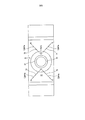
Согласно одному варианту выполнения предлагается, что в качестве первого заданного предельного значения используется максимальное отклонение горизонтального разреза фактической модели, относительно ориентации сегмента башни при использовании, от круга, соответственно, сегмента круга. Подлежащие изготовлению сегменты башни предусмотрены для расположения друг над другом при возведении бетонной башни ветроэнергетической установки. Поэтому необходимо выдерживать очень высокую точность посадки расположенных непосредственно друг над другом сегментов башни, а именно устанавливаемых друг над другом сегментов башни с целью обеспечения стабильности возводимой башни. Эти отклонения относятся к горизонтальному сечению, т.е. сечению поперек вертикальной оси бетонной башни. Они проявляются, в частности, при установке сегментов башни друг на друга, и поэтому должны выдерживаться, возможно, более точно.According to one embodiment, it is proposed that the maximum deviation of the horizontal section of the actual model, relative to the orientation of the tower segment when used, from the circle, respectively, of the circle segment, is used as the first predetermined limit value. The tower segments to be manufactured are intended to be located one above the other during the construction of a concrete tower of a wind power installation. Therefore, it is necessary to maintain a very high accuracy of landing of the tower segments located directly above each other, namely, the tower segments mounted on top of one another in order to ensure the stability of the tower being built. These deviations refer to the horizontal section, i.e. cross-section across the vertical axis of the concrete tower. They appear, in particular, when the tower segments are mounted on top of each other, and therefore should be maintained, perhaps more accurately.
В другом варианте выполнения предусмотрено, что изготовленные и измеренные сегменты башни выбраковываются, когда отклонение между виртуальной фактической моделью и заданной формой, в частности виртуальной заданной моделью, превышает второе заданное предельное значение, которое больше первого заданного предельного значения. Таким образом, предлагается контролирование двух предельных значений, и превышение первого предельного значения приводит лишь к исправлению бетонной формы, в частности опалубки, в то время как слишком сильное отклонение, которое превышает второе предельное значение, приводит также к отбраковке части. Таким образом, если превышается первое предельное значение, но второе предельное значение не превышено, то исходят из того, что изготовленный сегмент башни еще лежит внутри приемлемых пределов. Отклонения лишь настолько велики, что рекомендуется согласование бетонной формы, в частности опалубки, с целью улучшения следующего изготавливаемого сегмента башни. Таким образом, за счет контролирования первого предельного значения обеспечивается непрерывное контролирование и улучшение качества изготовленного сегмента башни и тем самым подлежащей возведению башни. В соответствии с этим первое предельное значение может быть выбрано очень малым.In another embodiment, it is provided that the fabricated and measured tower segments are discarded when the deviation between the virtual actual model and the predetermined shape, in particular the virtual predetermined model, exceeds a second predetermined limit value that is greater than a first predetermined limit value. Thus, it is proposed to control two limit values, and exceeding the first limit value only leads to the correction of the concrete form, in particular the formwork, while too strong a deviation that exceeds the second limit value also leads to rejection of the part. Thus, if the first limit value is exceeded, but the second limit value is not exceeded, then proceed from the fact that the manufactured tower segment still lies within acceptable limits. The deviations are only so great that matching the concrete form, in particular the formwork, is recommended in order to improve the next tower segment being manufactured. Thus, by controlling the first limit value, continuous monitoring and improvement of the quality of the manufactured tower segment and thereby the tower to be erected is ensured. Accordingly, the first limit value can be selected very small.
Лишь превышение второго предельного значения, что должно происходить, возможно, более редко, приводит к браку и тем самым к необходимости изготовления нового, улучшенного сегмента башни для замены отбракованного сегмента башни.Only exceeding the second limit value, which should happen, perhaps more rarely, leads to marriage and thereby to the need to manufacture a new, improved tower segment to replace the rejected tower segment.
Предпочтительно способ выполняется так, что в зависимости от определяемого отклонения вычисляется значение коррекции для изменения формы сегмента, соответственно, для изменения по меньшей мере одной образующей форму сегмента опалубки. За счет сравнения виртуальной фактической модели с виртуальной заданной моделью можно распознавать количественное и качественное отклонение. Соответственно, очень хорошо известны отклонения фактической модели от заданной модели по качеству, количеству и месту. Отсюда можно вычислять, соответственно, необходимые изменения опалубки, поскольку она представляет по существу негативную форму изготовленного и измеренного сегмента башни.Preferably, the method is performed such that, depending on the deviation being determined, a correction value is calculated for changing the shape of the segment, respectively, for changing at least one form-forming segment of the formwork. By comparing the virtual actual model with the virtual given model, quantitative and qualitative deviation can be recognized. Accordingly, the deviations of the actual model from the given model in quality, quantity and location are very well known. Hence, it is possible to calculate, accordingly, the necessary changes in the formwork, since it represents the essentially negative shape of the manufactured and measured segment of the tower.
Согласно изобретению, дополнительно к этому предлагается измерительное устройство для измерения сегмента башни с признаками пункта 7 формулы изобретения. В соответствии с этим предусмотрен измерительный прибор для измерения геометрических размеров сегмента башни, в частности лазерный измерительный прибор. Кроме того, предусмотрено устройство обработки данных, в частности компьютер, который предназначен для создания с помощью полученных с помощью измерительного прибора данных виртуальной модели и проведения сравнения виртуальной модели с заданной формой, в частности сравнение с уже существующей виртуальной моделью, т.е. сравнение фактической модели с заданной моделью.According to the invention, in addition to this, there is provided a measuring device for measuring a tower segment with the features of claim 7. Accordingly, a measuring device is provided for measuring the geometric dimensions of a tower segment, in particular a laser measuring device. In addition, a data processing device is provided, in particular a computer, which is designed to create virtual model data using a measuring device and to compare a virtual model with a given shape, in particular, a comparison with an existing virtual model, i.e. comparing the actual model with the given model.
Предпочтительно измерительное устройство предназначено для выполнения указанного выше способа. Если для способа необходимы другие элементы устройства, такие как бетонная форма, соответственно, опалубка, и/или устройство для изменения такой бетонной формы или опалубки, то они образуют, соответственно, часть измерительного устройства, которое, соответственно, можно называть также оптимирующим устройством или производственным устройством для сегмента башни. Предпочтительно измерительное устройство имеет крепежные средства, с помощью которых его можно закреплять на сегменте башни и/или опалубке с целью измерения этого сегмента башни, соответственно, изготовленного с ее помощью сегмента башни.Preferably, the measuring device is designed to perform the above method. If the method requires other elements of the device, such as a concrete form, respectively, formwork, and / or a device for changing such a concrete form or formwork, they form, respectively, a part of the measuring device, which, respectively, can also be called an optimizing device or production device for the tower segment. Preferably, the measuring device has fixing means by which it can be fixed on the tower segment and / or formwork in order to measure this tower segment, respectively, made with its help the tower segment.
Указанное измерение с последующим сравнением указанных моделей относится тем самым, в частности, к конечному контролированию, в котором готовые бетонные сегменты проверяют после изготовления с помощью способа лазерного измерения и соответствующего лазерного измерительного устройства. В частности, проверяется, правилен ли контур, в частности, являются ли сегменты действительно круглыми. При этом готовый сегмент измеряется с помощью лазерной измерительной системы и создается трехмерное изображение в компьютере, которое сравнивается с трехмерной моделью, т.е. идеальной формой. При этом целью является распознавание небольших отклонений и при необходимости соответствующее согласование опалубки. Так, например, можно распознавать легкие отклонения от оптимальной формы, после чего выполняют согласование опалубки, однако без отбраковки измеренного сегмента. Вместо этого предлагается выполнение заранее юстировки с целью оптимизации изготовления. При этом целью является и достигается точность в миллиметровом диапазоне, который является обычным в машиностроении, т.е. в металлообрабатывающем производстве, при сравнимой величине изготавливаемых предметов, но не в производстве бетонных частей такого порядка величины.The specified measurement, followed by a comparison of these models, relates, in particular, to the final control, in which the finished concrete segments are checked after manufacturing using the laser measurement method and the corresponding laser measuring device. In particular, it is checked whether the contour is correct, in particular, whether the segments are really round. In this case, the finished segment is measured using a laser measuring system and a three-dimensional image is created in the computer, which is compared with a three-dimensional model, i.e. perfect shape. The goal is to recognize small deviations and, if necessary, appropriate coordination of the formwork. So, for example, slight deviations from the optimal shape can be recognized, after which the formwork is matched, but without rejecting the measured segment. Instead, adjustments are suggested in advance to optimize manufacturing. At the same time, the aim is and is achieved accuracy in the millimeter range, which is common in engineering, i.e. in metal processing, with a comparable size of manufactured items, but not in the production of concrete parts of this order of magnitude.
Наконец, с помощью предложенного решения достигается также воспроизводимость изготавливаемых бетонных сегментов. Наряду с общим улучшением качества это обеспечивает также взаимозаменяемость элементов, которые могут быть, в принципе, идентичными, однако на основании колебаний изготовления не являются одинаковыми. За счет улучшения воспроизводимости можно взаимно заменять такие элементы. Это может быть преимуществом при складском хранении, поскольку больше нет необходимости в идентификации каждого отдельного сегмента, а лишь типов сегментов, включая их величину.Finally, using the proposed solution, reproducibility of the manufactured concrete segments is also achieved. Along with a general improvement in quality, this also ensures interchangeability of elements, which can, in principle, be identical, however, based on manufacturing fluctuations, they are not the same. By improving reproducibility, such elements can be mutually replaced. This can be an advantage in warehousing, since it is no longer necessary to identify each individual segment, but only the types of segments, including their size.
Дополнительно к этому согласно изобретению предлагается опалубка для изготовления сегмента башни бетонной башни ветроэнергетической установки, согласно пункту 9 формулы изобретения. Такая опалубка исходит из сегмента башни с внутренней вогнутой и наружной выпуклой поверхностью, что имеет место в цилиндрическом сегменте опалубки или сегменте опалубки в форме усеченного конуса. Для внутренней вогнутой поверхности, которая в соответствии с назначением обращена также внутрь подлежащей возведению бетонной башни, предусмотрен для задания формы внутренний элемент опалубки. Это может быть, например, цилиндр или усеченный конус или т.п. Для наружной выпуклой поверхности, которая должна образовывать по существу также часть наружной поверхности подлежащей возведению бетонной башни, предусмотрен соответствующий наружный элемент опалубки. Внутренний элемент опалубки можно называть также внутренней опалубкой или элементом внутренней опалубки, а наружный элемент опалубки можно называть также элементом наружной опалубки или наружной опалубкой.In addition to this, according to the invention, a formwork is proposed for manufacturing a tower segment of a concrete tower of a wind power installation according to claim 9. Such formwork comes from a tower segment with an internal concave and external convex surface, which takes place in a cylindrical formwork segment or a truncated cone shaped formwork segment. For the internal concave surface, which, in accordance with the purpose, also faces the concrete tower to be erected, an internal formwork element is provided for defining the shape. This may be, for example, a cylinder or a truncated cone, or the like. For the outer convex surface, which should also form essentially part of the outer surface of the concrete tower to be erected, a corresponding outer formwork element is provided. The inner formwork element may also be called the internal formwork or element of the inner formwork, and the outer formwork element may also be called the element of the outer formwork or outer formwork.
Оба элемента опалубки предназначены для составления вместе так, что между ними образуется приемное пространство для приема бетонной массы для отливки подлежащего изготовлению сегмента башни. Таким образом, оба элемента опалубки составляют вместе так, что получается кольцевой зазор или т.п. или же часть его.Both formwork elements are designed to be assembled together so that between them a receiving space is formed for receiving concrete mass for casting the tower segment to be manufactured. Thus, both formwork elements are combined so that an annular gap or the like is obtained. or part of it.
Наружная опалубка, т.е. наружный элемент опалубки, имеет ходовое устройство, в частности, несколько колес, с целью удаления наружной опалубки после затвердевания сегмента башни в горизонтальном направлении от сегмента башни для освобождения готового сегмента башни.External formwork, i.e. the outer formwork element has a running gear, in particular, several wheels, in order to remove the outer formwork after the tower segment has hardened in a horizontal direction from the tower segment to release the finished tower segment.
После удаления наружной опалубки изготовленный сегмент башни тем самым по существу освобождается на одной стороне, а своей другой, вогнутой стороной еще прилегает к внутренний опалубке. Тем не менее этот сегмент башни можно, например, с помощью цехового крана снимать с его места и перемещать для дальнейшей обработки, соответственно, дальнейшей транспортировки.After removal of the outer formwork, the manufactured tower segment is thereby essentially freed up on one side, and with its other, concave side, it is still adjacent to the inner formwork. Nevertheless, this segment of the tower can, for example, be removed from its place with the help of a workshop crane and moved for further processing, respectively, for further transportation.
До настоящего времени известно также поднимание опалубки с помощью цехового крана, часто с помощью того же цехового крана, с помощью которого поднимается бетонный сегмент. В основе этого лежит понимание того, что опалубка часто имеет вес, аналогичный весу изготовленного сегмента башни. Опалубка может иметь вес от 5 т до 10 т. Такой тяжелый объект едва ли поддается перемещению вручную, и поэтому применялись и применяются цеховые краны, которые могут справляться с таким весом. Однако заявителями было установлено, что перемещение вручную все же частично возможно, по меньшей мере можно при этом обойтись без цехового крана. За счет этого процесс упрощается и сокращается время использования цехового крана.To date, it is also known to lift the formwork using a workshop crane, often using the same workshop crane with which a concrete segment is lifted. This is based on the understanding that the formwork often has a weight similar to the weight of the manufactured tower segment. The formwork can have a weight of 5 tons to 10 tons. Such a heavy object can hardly be moved manually, and therefore shop cranes have been used and can handle this weight. However, the applicants found that manual movement is still partially possible, at least it is possible to do without a workshop crane. Due to this, the process is simplified and reduced the time of use of the workshop crane.
Заявителями было установлено, что хотя наружная опалубка имеет большой вес, однако ее необходимо сдвигать лишь на очень небольшой путь. К этому добавляется то, что полы в промышленных производственных цехах часто являются плоскими и горизонтальными. Таким образом, проблема сдвига тяжелой опалубки состоит в преодолении силы трения при горизонтальном перемещении опалубки. Поэтому предусмотрено ходовое устройство, которое должно уменьшать возможные силы трения. В частности, это достигается с помощью колес, соответственно, роликов.Applicants have found that although the outer formwork is heavy, it needs to be moved only a very short distance. To this is added that the floors in industrial production halls are often flat and horizontal. Thus, the problem of shear heavy formwork is to overcome the frictional force during horizontal movement of the formwork. Therefore, a running gear is provided, which should reduce possible frictional forces. In particular, this is achieved with the help of wheels, respectively, rollers.
Предпочтительно ходовое устройство имеет колеса или ролики для перемещения наружного элемента опалубки, т.е. наружной опалубки, по рельсам. Поскольку опалубка при удалении от изготовленного сегмента башни должна лишь освобождать его, а затем должна быть снова сдвинута в образующее форму положение, предпочтительным является перемещение по рельсам, потому что они задают направление и для перемещения опалубки не требуется дополнительной степени свободы. При сдвигании назад наружной опалубки в ее исходное положение для изготовления другого сегмента башни с помощью рельсов обеспечивается, что опалубка очень точно занимает предусмотренное для нее место. Дополнительно к этому это является существенно более простым по сравнению с применением цехового крана, поскольку не требуется сложного позиционирования.Preferably, the running gear has wheels or rollers for moving the outer formwork element, i.e. outer formwork, on rails. Since the formwork, when moving away from the manufactured tower segment, should only release it, and then should again be shifted to the position forming the shape, it is preferable to move along the rails because they set the direction and no additional degree of freedom is required to move the formwork. When the outer formwork is shifted back to its original position for the manufacture of another segment of the tower using rails, it is ensured that the formwork very accurately takes up the space provided for it. In addition to this, it is significantly simpler compared to the use of a workshop crane, since complex positioning is not required.
Предпочтительно предусмотрено рычажное средство для перемещения или сдвига наружной опалубки с целью также, в частности, отделения наружной опалубки от затвердевшего сегмента башни. За счет этого можно преодолевать силу адгезии, которая действует между только что затвердевшим сегментом башни и наружной опалубкой. Для этого необходимо перемещать наружную опалубку лишь на очень небольшое расстояние, и поэтому может быть предусмотрено очень большое рычажное действие. За счет этого можно оттягивать наружную опалубку от изготовленного сегмента башни, и при необходимости можно снова использовать такой рычаг для оттягивания дальше наружной опалубки. Предпочтительно непосредственно рядом с подлежащим оттягиванию элементом наружной опалубки в полу цеха или производственном полу выполнена точка опоры, к которой можно прикладывать такой рычаг, или же может быть предусмотрена вспомогательная опора, такая как, например, подкладка, которая лежит на полу цеха и сама упирается в предмет, такой как, например, цоколь, на котором отливают сегмент башни, которую можно называть также производственным полом. При этом вспомогательная опора имеет точку приложения, в частности, выемку и/или выступ для приложения рычага. При этом рычаг можно понимать в буквальном смысле, а именно в виде длинного металлического бруса или стальной трубы. Его можно приставлять к точке опоры, например вставлять в выемку, и немного выше, в нижней зоне закреплять на наружной опалубке. С помощью другого конца этого рычага, т.е. этого бруса или этой стальной трубы, обеспечивается возможность передачи большой силы. Отношение плеч рычага в этом примере зависит от отношения общей длины рычага к расстоянию точки опоры в полу цеха до точки опоры на наружной опалубке, а также от угла опрокидывания.Preferably, a lever means is provided for moving or shifting the outer formwork to also, in particular, separate the outer formwork from the hardened segment of the tower. Due to this, it is possible to overcome the adhesion force, which acts between the just hardened segment of the tower and the outer formwork. For this it is necessary to move the outer formwork only a very small distance, and therefore a very large lever action can be provided. Due to this, the outer formwork can be pulled back from the manufactured tower segment, and if necessary, such a lever can again be used to pull further the outer formwork. Preferably, immediately near the element of the outer formwork to be pulled off, a support point is made in the floor of the workshop or on the production floor, to which such a lever can be applied, or an auxiliary support, such as, for example, a lining, which lies on the floor of the workshop and itself rests against an object, such as, for example, a base on which a segment of a tower is cast, which can also be called a production floor. In this case, the auxiliary support has an application point, in particular, a recess and / or protrusion for applying the lever. In this case, the lever can be understood literally, namely in the form of a long metal bar or steel pipe. It can be attached to the fulcrum, for example, inserted into a recess, and a little higher, in the lower zone, fixed to the outer formwork. With the other end of this lever, i.e. of this bar or this steel pipe, it is possible to transmit a large force. The ratio of the lever arms in this example depends on the ratio of the total lever length to the distance of the fulcrum in the floor of the workshop to the fulcrum on the outer formwork, as well as the tipping angle.
Предпочтительно предусмотрено подъемное средство для приподнимания наружной опалубки, соответственно, наружного элемента опалубки после затвердевания сегмента башни, так что можно сегмент башни приподнимать так, что он опирается лишь на ходовое устройство. Для предотвращения вытекания жидкого бетона при заполнении и перед затвердеванием подвижная наружная опалубка должна во время процесса изготовления неподвижно опираться на опору, а именно так прочно и герметично, что предотвращается выход бетона. Для обеспечения возможности отделения так прочно установленной наружной опалубки предусмотрены указанные подъемные средства.Preferably, a lifting means is provided for lifting the outer formwork, respectively, of the outer formwork element after the hardening of the tower segment, so that the tower segment can be lifted so that it rests only on the running gear. To prevent liquid concrete from flowing out during filling and before hardening, the movable outer formwork must be supported by the support motionlessly during the manufacturing process, and it is so firm and tight that concrete is prevented from escaping. To enable the separation of so firmly installed outer formwork, said lifting means are provided.
Предпочтительно предусмотрено разделительное средство для отделения наружного элемента опалубки от сегмента башни, содержащее нажимное средство, в частности нажимной винт для приложения давления разделения для отделения наружного элемента опалубки от сегмента башни. Такое разделительное средство прочно закреплено на элементе наружной опалубки, и можно с помощью нажимного средства прикладывать давление к противоположному элементу, такому как другой наружный элемент опалубки той же бетонной формы, или другому предмету, или наоборот, разделительное средство расположено на противоположном элементе и для отделения упирается в наружный элемент опалубки и тем самым отдавливает его от сегмента башни.Preferably, a separation means is provided for separating the outer formwork element from the tower segment, comprising a pressing means, in particular a pressure screw for applying a separation pressure to separate the outer formwork element from the tower segment. Such a release agent is firmly fixed to the outer formwork element, and it is possible to apply pressure to the opposite element, such as another outer formwork element of the same concrete shape, or to another object, or vice versa, the release agent is located on the opposite element and abuts against separation into the outer formwork element and thereby squeezes it from the tower segment.
Предпочтительно опалубка подготовлена для инициирования движения подъема подъемного средства посредством винтового движения, в частности, с помощью пневматического винтоверта. За счет винтового движения достигается хорошая передача силы, при этом может быть обеспечено также самоторможение подъемного устройства. Предпочтительно предусмотрено приведение в действие с помощью пневматического винтоверта. Это означает, что подъемное устройство имеет соответствующее место приложения для такого пневматического винтоверта, в частности, что оно имеет для приведения в действие подвижную головку винта, например, шестигранную головку винта, с величиной от 16 до 32 мм. Дополнительно к этому подъемное устройство предпочтительно предназначено для обычной скорости вращения и обычного крутящего момента пневматического винтоверта.Preferably, the formwork is prepared to initiate a lifting movement of the lifting means by means of a helical movement, in particular by means of a pneumatic screwdriver. Due to the helical movement, a good transmission of force is achieved, while the self-braking of the lifting device can also be ensured. Preferably, actuation with a pneumatic screwdriver is provided. This means that the lifting device has an appropriate place of application for such a pneumatic screwdriver, in particular that it has a movable screw head, for example, a hexagonal screw head, with a size of 16 to 32 mm for driving. Additionally, the lifting device is preferably designed for normal rotational speed and normal torque of a pneumatic screwdriver.
В основе этого лежит понимание того, что приведение в действие подъемного устройства вручную для подъема тяжелой опалубки может требовать больших затрат времени и сил. За счет согласования с пневматическим винтовертом, который часто имеется в производственных цехах, его можно применять предпочтительно также для приведения в действие подъемного устройства. Таким образом, необходимые дополнительные затраты не велики. При этом подъемное средство, когда ходовое устройство имеет несколько распределено расположенных колес или роликов, распределено так, что для каждого ролика, каждого колеса, соответственно, каждой пары роликов или каждой пары колес, соответственно, каждой группы роликов или каждой группы колес предусмотрено подъемное средство. Например, на наружной опалубке может быть распределено три колеса с целью перемещения ее на трех колесах, при этом предусмотрены три подъемных средства, а именно одно для каждого колеса. Если наружную опалубку сначала устанавливают на полу цеха, соответственно, производственном полу для изготовления сегмента башни, то ее можно приподнимать посредством приведения в действие трех подъемных средств, так что она опирается лишь на указанные три колеса и может относительно просто сдвигаться по указанным трем рельсам. Предпочтительно разделительное средство также предназначено для приведения в действие с помощью пневматического винтоверта. Для этого разделительное средство, в частности нажимной винт, выполнен соответствующим образом, как и подъемное средство.This is based on the understanding that manually actuating a lifting device for lifting heavy formwork can be time consuming and expensive. By matching with a pneumatic screwdriver, which is often found in production halls, it can preferably also be used to drive a lifting device. Thus, the necessary additional costs are not large. In this case, the lifting means, when the running gear has several distributed wheels or rollers, is distributed so that for each roller, each wheel, respectively, each pair of rollers or each pair of wheels, respectively, each group of rollers or each group of wheels, lifting means are provided. For example, three wheels can be distributed on the outer formwork to move it on three wheels, while three lifting means are provided, namely one for each wheel. If the outer formwork is first installed on the floor of the workshop, respectively, the production floor for the manufacture of the tower segment, then it can be lifted by actuating three lifting means, so that it rests only on these three wheels and can relatively easily be moved along these three rails. Preferably, the release agent is also intended to be driven by a pneumatic screwdriver. For this, the separation means, in particular the pressure screw, is made accordingly, as well as the lifting means.
Согласно одному варианту выполнения, предлагается производственное устройство, которое имеет ходовые рельсы для направления ходового устройства указанного выше наружного элемента опалубки, который можно называть также наружной опалубкой. Предпочтительно ходовые рельсы расположены на полу, в частности, на полу цеха. Дополнительно к этому на полу предусмотрено место опоры для рычага. В частности, предусмотрена выемка для приложения рычага с целью по меньшей мере частичного оттягивания наружной опалубки от затвердевшего сегмента башни. Таким образом, такое производственное устройство относится к производственному цеху или его части, в которой предусмотрена наружная опалубка, согласно изобретению. Производственный цех согласован с указанной выше подвижной наружной опалубкой, в частности, относительно рельс и точки приложения рычага.According to one embodiment, a production device is proposed that has running rails for guiding the running gear of the above external formwork element, which may also be called external formwork. Preferably, the running rails are located on the floor, in particular on the floor of the workshop. In addition to this, a support leg for the lever is provided on the floor. In particular, a recess is provided for applying a lever to at least partially pull the outer formwork away from the hardened tower segment. Thus, such a production device relates to a production workshop or part thereof in which an external formwork is provided according to the invention. The production hall is aligned with the above-mentioned movable outer formwork, in particular with respect to the rail and the point of application of the lever.
Таким образом, это решение преодолевает проблемы прежнего изготовления бетонных сегментов, при котором элементы наружной опалубки, в частности конические половины опалубки, которые образуют указанную опалубку, перемещались с помощью крана. Согласно изобретению, предлагаются такие опалубки, которые могут быть половинами опалубки, третями опалубки или четвертями опалубки, выполнять с возможностью перемещения, а именно в частности, с опорой на систему рельс, с целью их сдвигания в положение для изготовления бетонного сегмента, соответственно, после затвердевания сегмента снова сдвигания или оттягивания. Предпочтительно предусмотрены разделительные средства, которые отдавливают две половины опалубки друг от друга и тем самым обеспечивают первое отделение такой половины опалубки или т.п., в частности, наружной опалубки от затвердевшего сегмента башни. Такое разделительное средство может действовать аналогично винту, иметь винт в качестве нажимного средства, а именно иметь нажимной винт, и преобразовывать вращение в осевую силу для разделения элементов. Это разделительное средство также выполнено так, что его можно приводить в действие с помощью пневматического винтоверта.Thus, this solution overcomes the problems of the previous manufacture of concrete segments, in which the elements of the outer formwork, in particular the conical halves of the formwork, which form the specified formwork, were moved using a crane. According to the invention, such formwork is proposed, which can be half of the formwork, thirds of the formwork or quarters of the formwork, can be moved, in particular with a support on the rail system, in order to shift them to the position for the manufacture of the concrete segment, respectively, after hardening segment again shifting or pulling. Separation means are preferably provided that squeeze the two halves of the formwork away from each other and thereby provide a first separation of such half of the formwork or the like, in particular the outer formwork from the hardened tower segment. Such a separation means can act similarly to a screw, have a screw as a pressure means, namely, have a pressure screw, and convert the rotation to axial force to separate the elements. This release means is also designed so that it can be actuated using a pneumatic screwdriver.
Подъемное средство может быть предпочтительно выполнено так, что действительное приподнимание опалубки происходит с помощью одной, соответственно, нескольких соответственно сильных пружин, а опускание опалубки в ее положение для изготовления бетонной части происходит за счет того, что винт действует против силы пружины, т.е. сжимает пружину. Предпочтительно это также предусмотрено для применения с указанным выше пневматическим винтовертом. Таким образом, соответствующие пружины могут быть выполнены так, что они лишь немного сильнее, чем это необходимо для подъема соответствующей опалубки. Для опускания опалубки необходима лишь такая сила давления, насколько сила пружины больше силы тяжести опалубки. Таким образом, если опалубка имеет вес, например, 10 т и пружины выбраны для 11 т, то для их сжатия требуется дополнительная сила, равная лишь 1 т, которая прикладывается с помощью указанных винтов. Без применения этих пружин необходимо с помощью винтов прикладывать подъемную силу для полного подъема, равную 10 т. Естественно, что указанные необходимые силы распределяются на несколько подъемных средств.The lifting means can preferably be made so that the actual lifting of the formwork occurs using one, respectively, several respectively strong springs, and lowering the formwork in its position for the manufacture of the concrete part is due to the fact that the screw acts against the force of the spring, i.e. compresses the spring. Preferably, it is also provided for use with the above pneumatic screwdriver. Thus, the corresponding springs can be made so that they are only slightly stronger than necessary to lift the corresponding formwork. To lower the formwork, only such a pressure force is needed as the spring force is greater than the formwork gravity. Thus, if the formwork has a weight of, for example, 10 tons and the springs are selected for 11 tons, then for their compression, an additional force of only 1 ton is required, which is applied using the indicated screws. Without the use of these springs, it is necessary to use a screw to apply a lifting force for a full lift of 10 tons. Naturally, these necessary forces are distributed over several lifting means.
Дополнительно к этому предлагается способ изготовления сегмента башни ветроэнергетической установки, согласно пункту 17 формулы изобретения. В соответствии с этим последовательно выполняются следующие стадии изготовления.In addition to this, a method for manufacturing a tower segment of a wind power plant according to paragraph 17 of the claims is proposed. Accordingly, the following manufacturing steps are sequentially performed.
Сначала заливают бетонную массу между элементом внутренней опалубки и элементом наружной опалубки, которая затвердевает в следующей стадии. После затвердевания элемент отделяют от ответного элемента, такого как другой наружный элемент опалубки. Для этого, в частности, один или несколько винтов наружного элемента опалубки завинчивают с упором в ответный элемент с целью обеспечения за счет этого разделения. В частности, при этом преодолевается сила адгезии между соответствующим элементом наружной опалубки и отлитым и затвердевшим сегментом башни.First, concrete mass is poured between the element of the inner formwork and the element of the outer formwork, which hardens in the next stage. After solidification, the element is separated from the response element, such as another outer formwork element. For this, in particular, one or more screws of the outer formwork element are screwed into the mating element with an emphasis in order to ensure this separation. In particular, the adhesive force between the corresponding element of the outer formwork and the cast and hardened segment of the tower is overcome.
Затем приподнимают наружный элемент опалубки с помощью соответствующего подъемного средства, так что он опирается лишь на расположенное на элементе наружной опалубки ходовое устройство. Наконец, можно опирающийся так наружный элемент опалубки отодвигать в горизонтальном направлении с применением ходового устройства. Предпочтительно приподнимание осуществляется с помощью подъемного средства, которое неподвижно соединено с ходовым устройством, при этом подъемное средство приводят в действие с помощью автоматического винтоверта, в частности пневматического винтоверта, с целью осуществления приподнимания. Предпочтительно при изготовлении бетонного сегмента наружный элемент опалубки сначала опускают с помощью подъемного средства посредством приведения в действие с помощью автоматического винтоверта.Then, the outer formwork element is lifted using an appropriate lifting means, so that it relies only on the running gear located on the outer formwork element. Finally, the outer formwork element supported in this way can be moved horizontally using a running gear. Preferably, the lifting is carried out by means of a lifting means which is fixedly connected to the running device, wherein the lifting means is driven by an automatic screwdriver, in particular a pneumatic screwdriver, in order to carry out the lifting. Preferably, in the manufacture of the concrete segment, the outer formwork element is first lowered by means of lifting means by actuation using an automatic screwdriver.
В частности, в таком способе изготовления применяют указанную выше опалубку и/или указанное выше производственное устройство для изготовления сегментов башни с применением такой опалубки.In particular, in such a manufacturing method, the aforementioned formwork and / or the aforementioned manufacturing device are used to manufacture tower segments using such a formwork.
Согласно изобретению, дополнительно предлагается бетонная башня ветроэнергетической установки, согласно пункту 21 формулы изобретения. Она содержит несколько установленных друг на друга сегментов башни различной величины из бетона, которые изготовлены из железобетона, т.е. имеют стальную арматуру. Таким образом, башня возводится из готовых бетонных частей. При этом форма бетонной башни выбрана так, что она имеет наружный контур, который соответствует экспоненциальной функции. Другими словами, такая бетонная башня, уложенная горизонтально так, что ее вершина лежит слева, а ее основание справа, имеет контур, верхняя линия которого соответствует обычной экспоненциальной функции.According to the invention, a concrete tower of a wind power installation according to claim 21 is further provided. It contains several tower segments mounted on top of each other of various sizes made of concrete, which are made of reinforced concrete, i.e. have steel reinforcement. Thus, the tower is built from prefabricated concrete parts. Moreover, the shape of the concrete tower is chosen so that it has an external contour that corresponds to an exponential function. In other words, such a concrete tower, laid horizontally so that its vertex lies on the left, and its base on the right, has a contour whose upper line corresponds to the usual exponential function.
В частности, окружность U бетонной башни уменьшается с окружности U0 в нижней зоне бетонной башни, исходя снова из стоячего положения, в соответствии с предназначением, в частности, у основания башни над фундаментом, с увеличением высоты h, в соответствии с экспоненциальной функцией, а именно в соответствии с формулой:In particular, the circumference U of the concrete tower decreases from the circle U 0 in the lower zone of the concrete tower, proceeding again from a standing position, in accordance with the purpose, in particular, at the base of the tower above the foundation, with an increase in height h, in accordance with the exponential function, and in accordance with the formula:
U=U0*e-h*c.U = U 0 * e -h * c .
Переменную с можно применять в качестве регулировочного коэффициента для регулирования растяжения или подъема. Одновременно регулировочный коэффициент с применяется для нормирования экспоненты, так что экспонента является безразмерной.Variable c can be used as an adjustment factor to control stretching or lifting. At the same time, the adjustment coefficient c is used to normalize the exponent, so that the exponent is dimensionless.
За счет применения этого наружного контура, соответственно, увеличения, соответственно, уменьшения окружности в соответствии с экспоненциальной функцией, получается башня из готовых частей, которая по существу в своей верхней зоне выполнена тонкой и одновременно имеет стабильное основание башни, при этом переходы являются непрерывными. Узкая верхняя часть башни имеет, в частности, значение для ветроэнергетических установок, поскольку башня для каждой проходящей мимо лопасти ротора представляет зону неподвижного воздуха, которая должна удерживаться, возможно, меньшей.Due to the use of this external contour, respectively, increase, respectively, decrease the circumference in accordance with the exponential function, a tower of finished parts is obtained, which is essentially thin in its upper zone and at the same time has a stable tower base, while the transitions are continuous. The narrow upper part of the tower is, in particular, important for wind power installations, since the tower for each passing rotor blade represents a zone of still air, which should be kept, possibly smaller.
Для возведения такой бетонной башни с контуром, соответствующим экспоненциальной функции, из готовых бетонных частей, их необходимо изготавливать соответствующим образом. Опалубки, которые применяются для изготовления соответствующих сегментов башни, должны быть, соответственно, согласованы с целью обеспечения указанной экспоненциальной функции во всей бетонной башне.For the construction of such a concrete tower with a contour corresponding to an exponential function, from the finished concrete parts, they must be manufactured accordingly. The formwork used for the manufacture of the corresponding tower segments must be accordingly coordinated in order to ensure the indicated exponential function in the entire concrete tower.
Экспоненциальная функция может быть также приближена с помощью сегментов башни с образованием полигональной линии, в частности, с помощью сегментов с соответствующим прямым, т.е. не изогнутым участком контура.The exponential function can also be approximated using the segments of the tower with the formation of a polygonal line, in particular, using segments with the corresponding straight lines, i.e. not a curved portion of the contour.
Согласно изобретению, дополнительно предлагается группа бетонных башен по меньшей мере с одной первой и одной второй бетонной башней ветроэнергетической установки, согласно пункту 23 формулы изобретения. Каждая из этих бетонных башен имеет несколько установленных друг на друга сегментов башни различной величины из бетона. Сегмент башни или несколько расположенных на одинаковой высоте сегментов башни образуют сегментную плоскость. В простейшем случае, в частности, в верхней зоне башни, сегментная плоскость может быть образована с помощью единственного, имеющего по существу форму боковой поверхности усеченного конуса сегмента башни. В более крупных, в частности, расположенных дальше внизу сегментных плоскостях, они могут быть составлены из нескольких, например, из двух половин опалубки.According to the invention, a group of concrete towers with at least one first and one second concrete tower of a wind power installation according to claim 23 is further provided. Each of these concrete towers has several segments of a tower of various sizes made of concrete mounted on top of each other. A tower segment or several tower segments located at the same height form a segment plane. In the simplest case, in particular in the upper zone of the tower, the segment plane can be formed using a single, essentially shaped lateral surface truncated cone segment of the tower. In larger, in particular, located further below the segmented planes, they can be composed of several, for example, two halves of the formwork.
При этом группа бетонных башен имеет по меньшей мере две различно большие башни, при этом первая башня больше второй башни, а именно имеет больше сегментных плоскостей, чем вторая башня, имеет по меньшей мере одну дополнительную сегментную плоскость по сравнению со второй башней. При этом предлагается, что первая и вторая башня имеют сегментные плоскости с одинаковыми сегментами башни, но на различной высоте.Moreover, the group of concrete towers has at least two differently large towers, while the first tower is larger than the second tower, namely it has more segmented planes than the second tower, has at least one additional segmented plane compared to the second tower. It is proposed that the first and second towers have segmented planes with identical tower segments, but at different heights.
Таким образом, предлагается применять для различных бетонных башен одинаковые сегментные плоскости и тем самым применять для различных башен одинаковые сегменты башни. В частности, предлагается применение бетонных башен, которые имеют указанный выше наружный контур в соответствии с экспоненциальной функцией. Однако относительно приведенной выше формулы это означает, что окружность U0 у основания башни для различно больших башен также является различно большой. Предпочтительно башни имеют одни и те же участки в их верхней зоне. Проще говоря, большая башня соответствует меньшей башне, при этом некоторые сегменты башни еще установлены под этой меньшей башней. Фактическое возведение башни осуществляется, естественно, по-другому, а именно последовательно от фундамента, т.е. начиная с основания башни.Thus, it is proposed to use the same segmented planes for different concrete towers and thereby apply the same tower segments to different towers. In particular, it is proposed the use of concrete towers that have the above external contour in accordance with an exponential function. However, with respect to the above formula, this means that the circle U 0 at the base of the tower for differently large towers is also differently large. Preferably, the towers have the same sections in their upper zone. Simply put, a large tower corresponds to a smaller tower, with some segments of the tower still mounted under this smaller tower. The actual construction of the tower is carried out, naturally, in a different way, namely, sequentially from the foundation, i.e. starting from the base of the tower.
Если, например, группа бетонных башен содержит первую бетонную башню с 20 сегментными плоскостями и вторую бетонную башню с 10 сегментными плоскостями, при этом, соответственно, первую сегментную плоскость образует самый верхний сегмент, а двадцатую сегментную плоскость большой башни, соответственно, десятую сегментную плоскость малой башни образует самый нижний сегмент, то для этого примера предлагается, что от первой до десятой сегментной плоскости большой башни и малой башни они являются одинаковыми. Таким образом, для возведения большой башни можно использовать первую – десятую сегментные плоскости малой башни. При этом некоторые детали могут быть различными. В частности, десятая сегментная плоскость малой башни может иметь отверстие для двери, которая не предусмотрена в десятой сегментной плоскости большой башни.If, for example, a group of concrete towers contains a first concrete tower with 20 segment planes and a second concrete tower with 10 segment planes, while, respectively, the first segment plane forms the uppermost segment, and the twentieth segment plane of the large tower, respectively, the tenth segment plane of the small If the tower forms the lowest segment, then for this example it is suggested that from the first to the tenth segment plane of a large tower and a small tower they are the same. Thus, for the construction of a large tower, you can use the first - tenth segment planes of a small tower. However, some details may be different. In particular, the tenth segment plane of the small tower may have an opening for a door that is not provided in the tenth segment plane of the large tower.
Таким образом, для возведения башен необходимо изготавливать лишь сегменты башни для в целом 20 различных сегментных плоскостей вместо 30 различных сегментных плоскостей. Если должна быть возведена другая, средняя башня, которая имеет, например, 15 сегментных плоскостей, то не требуется предусмотрения сегмента башни с новой величиной. В этом случае для этих названных в качестве примера трех бетонных башен требуется изготовление сегментов башни лишь для 20 различных сегментных плоскостей башни вместо 45 сегментных плоскостей.Thus, for tower construction, it is only necessary to produce tower segments for a total of 20 different segment planes instead of 30 different segment planes. If another, middle tower, which has, for example, 15 segment planes, is to be erected, it is not necessary to provide a tower segment with a new value. In this case, for these three concrete towers named as an example, the manufacture of tower segments is required for only 20 different segmented planes of the tower instead of 45 segmented planes.
Особенно предпочтительно это сказывается в бетонных башнях с имеющим форму в соответствии с экспоненциальной функцией контуром башни. В этом случае имеющая форму, в соответствии с экспоненциальной функцией, большая башня ветроэнергетической установки имеет в своей зоне экспоненциальную форму, которая соответствует экспоненциальной форме меньшей башни. При этом также большая башня имеет общий контур, в соответствии с экспоненциальной функцией, без ломаных или по-другому дискретных переходов. Форма в соответствии с экспоненциальной функцией обеспечивает возможность указанного модульного возведения башен различной величины.This is particularly advantageous in concrete towers having a contour shaped in accordance with the exponential function of the tower. In this case, having the shape, in accordance with the exponential function, the large tower of the wind power installation has an exponential shape in its area, which corresponds to the exponential shape of the smaller tower. Moreover, the large tower also has a common contour, in accordance with the exponential function, without broken lines or otherwise discrete transitions. The shape in accordance with the exponential function allows the indicated modular construction of towers of various sizes.
Кроме того, предлагается ветровой парк, который содержит бетонную башню, согласно изобретению, соответственно, группу бетонных башен, согласно изобретению, с бетонными башнями. При этом под ветровым парком понимается система из нескольких ветроэнергетических установок, которые имеют, каждая, бетонную башню и которые подвергаются общему управлению и/или используют одну общую точку соединения для подачи электрической энергии в электрическую сеть.In addition, a wind park is proposed which comprises a concrete tower, according to the invention, respectively, a group of concrete towers, according to the invention, with concrete towers. At the same time, a wind park is understood to mean a system of several wind power plants that each have a concrete tower and which are subjected to general control and / or use one common connection point for supplying electric energy to the electric network.
Согласно изобретению, дополнительно предлагается способ изготовления бетонных башен ветроэнергетических установок, согласно пункту 26 формулы изобретения. В соответствии с этим, в основу положены бетонные башни со многими установленными друг на друга сегментами башни различной величины. Таким образом, способ относится к изготовлению бетонных башен из готовых бетонных частей.According to the invention, a method for manufacturing concrete towers of wind power plants according to
Сначала изготавливают сегменты башни с 1–k различными величинами. При этом k является целым положительным числом больше 2, при этом для каждой величины от 1 до k изготавливают по меньшей мере один сегмент башни. Для одной плоскости можно применять также больше сегментов башни, как, например, две получаши.First, tower segments with 1 – k different sizes are made. Moreover, k is a positive integer greater than 2, with at least one tower segment being made for each value from 1 to k. For one plane, you can also use more segments of the tower, such as two half-towers.
Затем из изготовленных сегментов башни выбирают множество сегментов башни для возведения бетонной башни, при этом выбор зависит от величины подлежащей возведению бетонной башни. Для возведения бетонной башни первой величины применяют по меньшей мере один сегмент башни каждой из величин 1–k. Для возведения бетонной башни второй величины применяют по меньшей мере один сегмент башни каждой из величин 1–j. Переменная j является целым числом больше 1 и меньше k. При этом бетонная башня второй величины меньше бетонной башни первой величины, и для возведения меньшей бетонной башни требуется меньше сегментов башни, чем для возведения большей бетонной башни. Наконец, возводят соответствующую башню с применением выбранных сегментов башни.Then, from the manufactured tower segments, a plurality of tower segments are selected for the erection of the concrete tower, the choice depending on the size of the concrete tower to be erected. For the construction of a concrete tower of the first magnitude, at least one tower segment of each of the 1 – k values is used. For the erection of a concrete tower of the second magnitude, at least one tower segment of each of the values 1 – j is used. The variable j is an integer greater than 1 and less than k. In this case, the concrete tower of the second magnitude is smaller than the concrete tower of the first magnitude, and for the construction of a smaller concrete tower requires fewer segments of the tower than for the construction of a larger concrete tower. Finally, erect the appropriate tower using selected segments of the tower.
Другими словами, в способе предлагается выбирать при возведении башни необходимые сегменты башни лишь в зависимости от ее величины и при этом применять для больших и малых башен одинаковые сегменты башни. Таким образом, сегменты башни величины 1–j предусмотрены для большой и малой башни. Для большой башни требуются лишь дополнительно сегменты башни величин от j+1 до k, соответственно, величины k, когда j+1 идентично k.In other words, in the method it is proposed to select the necessary tower segments during the construction of the tower only depending on its size and at the same time apply the same tower segments for large and small towers. Thus, tower segments of magnitude 1 – j are provided for the large and small towers. For a large tower, only additional segments of a tower of values from j + 1 to k are required, respectively, of a value of k, when j + 1 is identical to k.
Предпочтительно сегменты башни величины 1–j для возведения второй, меньшей бетонной башни идентичны с сегментами башни величины 1–j для возведения второй, большей бетонной башни.Preferably, tower segments of magnitude 1 – j for the construction of a second, smaller concrete tower are identical with segments of a tower of magnitude 1 – j for the construction of a second, larger concrete tower.
Таким образом, целесообразно, что для возведения бетонной башни первой величины применяются те же сегменты башни, что и для возведения бетонной башни второй величины и дополнительно применяются другие сегменты башни для возведения бетонной башни первой величины. При этом применяются одинаковые сегменты башни для верхней зоны башни, а другие сегменты башни, которые не применяются в меньшей башне, применяются для нижней зоны башни, которая расположена, соответственно, под верхней зоной башни.Thus, it is advisable that for the construction of a concrete tower of the first magnitude, the same tower segments are used as for the construction of a concrete tower of the second magnitude and additionally other segments of the tower are used for the construction of a concrete tower of the first magnitude. The same tower segments are used for the upper zone of the tower, and other segments of the tower, which are not used in the smaller tower, are used for the lower zone of the tower, which is located, respectively, under the upper zone of the tower.
Предпочтительно воздвигаются указанные выше бетонные башни или бетонные башни для указанных выше групп бетонных башен, или бетонные башни для указанного выше ветрового парка.Preferably, the above concrete towers or concrete towers for the above groups of concrete towers or concrete towers for the aforementioned wind park are erected.
Дополнительно к этому предлагается сегмент башни для возведения бетонной башни ветроэнергетической установки, который предназначен для возведения указанной выше бетонной башни или указанной выше группы бетонных башен. В частности, сегмент башни соответственно согласован с формой подлежащей возведению бетонной башни с целью образования в готовом состоянии башни ее частичного участка.In addition to this, a tower segment is proposed for the construction of a concrete tower of a wind power installation, which is intended for the construction of the above concrete tower or the above group of concrete towers. In particular, the tower segment is accordingly aligned with the shape of the concrete tower to be erected in order to form a partial section of the tower in the finished state.
Согласно изобретению, предлагается крепежный анкер для фиксации сегмента башни подлежащей возведению бетонной башни ветроэнергетической установки при транспортировке сегмента башни на низкорамном прицепе, согласно пункту 30 формулы изобретения. Этот крепежный анкер имеет подлежащий бетонированию в сегменте башни анкерный участок. Через него затем должны вводиться в сегмент башни нагрузки на растяжение. Кроме того, предусмотрена неподвижно соединенная с анкерным участком удлиненная, в частности, цилиндрическая зона ствола. Эта зона ствола подготовлена для бетонирования в сегменте башни так, что противоположная анкерному участку соединительная сторона заканчивается заподлицо с наружной стороной сегмента башни. Зона ствола имеет внутреннюю резьбу для ввинчивания соединительной проушины для крепления серьги. Кроме того, или в качестве альтернативного решения, анкерная зона имеет увеличенный относительно зоны ствола участок для неподвижного удерживания в сегменте башни и передачи нагрузок растяжения в сегмент башни.According to the invention, a fastening anchor is provided for fixing a tower segment of a concrete tower of a wind power plant to be erected when transporting a tower segment on a low loader trailer according to
Этот крепежный анкер предназначен для неподвижного бетонирования в сегмент башни, в частности, в стенку сегмента башни, при этом снаружи доступно лишь одно отверстие, в частности, для ввинчивания там другого крепежного средства. Так, можно ввинчивать крепежную проушину и на ней, например, с помощью серьги, неподвижно крепить сегмент башни на низкорамном прицепе.This fixing anchor is designed for stationary concreting into the tower segment, in particular, into the wall of the tower segment, while only one hole is accessible from the outside, in particular, for screwing in another fixing means there. So, you can screw the mounting eye and on it, for example, using an earring, still fix the tower segment on a low loader trailer.
Предпочтительно крепежный анкер изготовлен из стали с целью обеспечения возможности восприятия большой нагрузки.Preferably, the fastening anchor is made of steel in order to allow the perception of a large load.
Согласно изобретению, дополнительно предлагается сегмент башни, согласно пункту 32 формулы изобретения, для возведения бетонной башни ветроэнергетической установки. Он характеризуется тем, что предусмотрен заделанный в стенку сегмента башни или проходящий через стенку крепежный анкер с целью фиксации, в частности, крепления сегмента башни при транспортировке на низкорамном прицепе с помощью крепежного анкера, при этом крепежный анкер имеет доступную снаружи внутреннюю резьбу для ввинчивания соединительной проушины для крепления серьги.According to the invention, a tower segment according to
В таком сегменте башни применяется, в частности, указанный выше крепежный анкер и тем самым его можно предпочтительно закреплять при транспортировке на низкорамном прицепе. Эта возможность крепления с помощью внутренней резьбы крепежного анкера обеспечивает возможность целенаправленного крепления на низкорамном прицепе. Соответствующие крепежные ремни или крепежные тросы или крепежные цепи необходимо лишь закреплять на крепежном анкере и на низкорамном прицепе. В зависимости от положения крепежного анкера в сегменте башни можно применять короткие крепежные ремни или т.п. Дополнительно к этому крепежный анкер задает четко определенную точку воздействия, которая не может соскальзывать. Дополнительно к этому указанную соединительную проушину можно после транспортировки просто вывинчивать из сегмента башни, а именно из крепежного анкера, так что она затем не создает помех при последующем возведении бетонной башни. При необходимости остающееся отверстие крепежного анкера на наружной стороне сегмента можно закрывать заглушкой.In this segment of the tower, in particular, the aforementioned fixing anchor is used, and thus it can preferably be secured during transportation on a low loader trailer. This possibility of fastening with the internal thread of the mounting anchor provides the possibility of targeted mounting on a low loader trailer. Corresponding fastening belts or fastening cables or fastening chains need only be fixed on the fastening anchor and on the low loader trailer. Depending on the position of the mounting anchor in the tower segment, short straps or the like can be used. In addition to this, the fixing anchor defines a clearly defined impact point that cannot slide off. In addition to this, the indicated connecting eye can be simply unscrewed from the tower segment after transportation, namely from the mounting anchor, so that it then does not interfere with the subsequent construction of the concrete tower. If necessary, the remaining hole of the mounting anchor on the outside of the segment can be closed with a plug.
Предпочтительно такой крепежный анкер бетонируют при изготовлении соответствующего бетонного сегмента. Если такое бетонирование не выполнялось, то можно с помощью последующего сверления отверстия вводить согласованный с этим отверстием крепежный анкер частично через боковую стенку и применять для крепления при транспортировке.Preferably, such a fixing anchor is concreted in the manufacture of the corresponding concrete segment. If such concreting has not been carried out, then, using the subsequent drilling of the hole, it is possible to introduce a fixing anchor compatible with this hole partially through the side wall and be used for fastening during transportation.
Предпочтительно крепежный анкер имеет удлиненную, в частности, цилиндрическую зону ствола, которая снабжена на одной стороне анкерной зоной, а на другой стороне – отверстием с внутренней резьбой. Зону ствола предпочтительно бетонируют в сегмент башни так, что она одной стороной заканчивается заподлицо с поверхностью сегмента башни так, что обеспечивается возможность ввинчивания снаружи соединительной проушины во внутреннюю резьбу.Preferably, the anchor anchor has an elongated, in particular cylindrical, trunk region, which is provided on one side with an anchor zone and on the other side with an internal threaded hole. The barrel area is preferably concreted into the tower segment so that it ends flush on one side with the surface of the tower segment so that it is possible to screw the connection eye from the outside into the internal thread.
Согласно изобретению предлагается фиксирующее устройство. Такое фиксирующее устройство содержит указанный выше крепежный анкер, соединительный винт для ввинчивания во внутреннюю резьбу крепежного анкера, при этом этот соединительный винт имеет крепежный участок для затягивания в нем серьги, такой как, например, проушина, и, необязательно, такая серьга предусмотрена для крепления на соединительном винте в качестве части фиксирующего устройства. За счет этого можно простым образом обеспечивать надежное крепление сегмента башни с помощью одного или нескольких таких фиксирующих устройств.According to the invention, a locking device is provided. Such a fixing device comprises the above fixing anchor, a connecting screw for screwing into the internal thread of the fixing anchor, while this connecting screw has a fixing section for tightening an earring, such as an eye, for example, and, optionally, such an earring is provided for mounting on connecting screw as part of a locking device. Due to this, it is possible in a simple manner to ensure reliable fastening of the tower segment using one or more of these locking devices.
Предпочтительно соединительный винт имеет опорный край для опоры соединительного винта во ввинченном состоянии на стенку сегмента башни. Если крепежный анкер забетонирован в сегмент башни так, что отверстие с внутренней резьбой заканчивается заподлицо с поверхностью соответствующего сегмента башни, то в него можно ввинчивать соединительный винт с опорным краем, пока опорный край не упрется в стенку сегмента башни. За счет этого достигается прочное и защищенное от опрокидывания соединение соединительного винта с сегментом башни. Внутренняя резьба, в которую ввинчивается винт, создает нагрузку на растяжение и предотвращает выход винта из сегмента башни. При этом опорный край предотвращает движение опрокидывания соединительного винта. Это предпочтительно, в частности, для крепления, которое проходит не в осевом направлении соединительного винта, соответственно, внутренней резьбы, а наклонно или даже перпендикулярно ему.Preferably, the connecting screw has a supporting edge for supporting the connecting screw in a screwed state on the wall of the tower segment. If the fastening anchor is concreted into the tower segment so that the hole with the internal thread ends flush with the surface of the corresponding tower segment, then a connecting screw with a supporting edge can be screwed into it until the supporting edge abuts against the wall of the tower segment. Due to this, a strong and tilt-protected connection of the connecting screw with the tower segment is achieved. The internal thread into which the screw is screwed creates a tensile load and prevents the screw from leaving the tower segment. In this case, the support edge prevents the tipping motion of the connecting screw. This is preferable, in particular, for fastening, which does not extend in the axial direction of the connecting screw, respectively, of the internal thread, but inclined or even perpendicular to it.
Необязательно предусмотрена буферная шайба для расположения между опорным краем и стенкой сегмента. Эта буферная шайба может быть изготовлена, например, из пластмассового материала с целью восприятия эластичностей и/или компенсации небольших неточностей стенки сегмента.A buffer washer is optionally provided for positioning between the abutment edge and the segment wall. This buffer washer can be made, for example, of a plastic material in order to perceive elasticities and / or to compensate for small inaccuracies in the segment wall.
Согласно изобретению, дополнительно предлагается способ изготовления сегмента башни в соответствии с пунктом 38 формулы изобретения. Он относится к сегменту башни для возведения бетонной башни ветроэнергетической установки. Сначала подготавливают опалубку для отливки сегмента башни в виде готовой бетонной части. Затем, соответственно, при этом располагают указанный выше крепежный анкер в желаемом положении и фиксируют так, что он при заливке бетона в опалубку сохраняет свое положение. Затем заливают бетон в опалубку, так что возникает сегмент башни с залитым в заданном положении крепежным анкером.According to the invention, a method for manufacturing a tower segment in accordance with
Таким образом, изготавливается указанный выше сегмент башни с заделанным крепежным анкером.Thus, the aforementioned tower segment is made with a fixed anchor anchor.
В принципе, указанные способы изготовления сегментов башни или возведения бетонных башен можно комбинировать друг с другом, соответственно, комбинировать друг с другом отдельные признаки из отдельных указанных способов, если это технически не противоречиво. Можно комбинировать также указанные сегменты башни в том смысле, что можно применять поясненные в другом контексте признаки, если они технически не противоречивы. То же относится к указанным бетонным башням. В них можно также, в принципе, комбинировать все указанные признаки, если это технически не противоречиво.In principle, these methods of manufacturing segments of the tower or the construction of concrete towers can be combined with each other, respectively, to combine with each other individual features from the individual specified methods, if this is not technically inconsistent. You can also combine these segments of the tower in the sense that you can apply the features explained in a different context, if they are not technically contradictory. The same applies to the indicated concrete towers. In them, it is also possible, in principle, to combine all the indicated features, if this is not technically inconsistent.
Например, сегмент башни, который предусмотрен для возведения бетонной башни с формой контура в соответствии с экспоненциальной функцией, может иметь крепежный анкер или другое вспомогательное средство для фиксации при транспортировке, как было описано в другом месте.For example, a tower segment, which is designed to erect a concrete tower with a contour shape in accordance with an exponential function, may have a fixing anchor or other auxiliary means for fixing during transportation, as described elsewhere.
Ниже приводится описание изобретения на основе примеров выполнения со ссылками на прилагаемые чертежи, на которых изображено:The following is a description of the invention based on exemplary embodiments with reference to the accompanying drawings, in which:
фиг.1 - ветроэнергетическая установка в изометрической проекции;figure 1 - wind power installation in isometric projection;
фиг.2 – опалубка для сегмента башни в изометрической проекции;figure 2 - formwork for a segment of the tower in an isometric view;
фиг.3 – часть подвижной опалубки с рычажной системой и частью устройства для перемещения в изометрической проекции;figure 3 - part of the movable formwork with a lever system and part of the device for moving in isometric projection;
фиг.4 – часть подвижной опалубки, включая часть подъемного средства и разделительное средство для отделения друг от друга двух половин опалубки в увеличенном масштабе;figure 4 - part of the movable formwork, including part of the lifting means and separation means for separating from each other two halves of the formwork on an enlarged scale;
фиг.5 – частичный разрез фиксирующего устройства для фиксации сегмента башни при транспортировке в предусмотренном для использования положении на виде сбоку;5 is a partial sectional view of a fixing device for fixing a tower segment during transportation in a side view position for use;
фиг.6 – крепежный анкер в изометрической проекции;6 is a mounting anchor in an isometric view;
фиг.7 – соединительная проушина с установленной серьгой на виде сверху;7 is a connecting eye with an installed earring in a top view;
фиг.8 – закрепленный с помощью двух фиксирующих устройств сегмент башни на низкорамном прицепе на виде сбоку;FIG. 8 is a side view of a tower segment mounted using two locking devices on a low loader trailer;
фиг.9 - сегмент башни, согласно фиг.8, на виде сверху.Fig.9 is a segment of the tower, according to Fig.8, in a top view.
Ниже приводятся в качестве примеров некоторые аспекты данного изобретения на основе примеров выполнения. Хотя некоторые аспекты поясняются отдельно, их можно также комбинировать в смысле данного изобретения, если это технически не противоречиво. Ниже могут применяться одинаковые позиции для аналогичных, но, возможно, не идентичных признаков. Однако, в любом случае, одинаковыми позициями обозначаются функционально одинаковые признаки.The following are examples of some aspects of the present invention based on exemplary embodiments. Although some aspects are explained separately, they can also be combined in the sense of the present invention, if this is not technically inconsistent. The same entries may apply below for similar but possibly not identical characteristics. However, in any case, the same positions denote functionally the same features.
На фиг.2 показана опалубка 1, которая предназначена для изготовления сегмента башни, имеющего примерно форму боковой поверхности усеченного конуса. В качестве альтернативного решения, могут быть предусмотрены, в принципе, также две половины опалубки, которые при составлении вместе имеют примерно форму боковой поверхности усеченного конуса. Для этого опалубка имеет внутренний элемент опалубки, а также два имеющих форму получаши наружных элемента 2 опалубки. Оба наружных элемента 2 опалубки неподвижно составлены вместе на двух контактных краях 4 и образуют вместе окружающую сегмент башни, соответственно, подлежащий изготовлению сегмент башни, боковую поверхность усеченного конуса. На контактных краях 4 эти образованные в виде получаш наружные элементы опалубки неподвижно соединены друг с другом с помощью соединительных винтов 6. Между этими обоими соединенными так наружными элементами 2 опалубки и не изображенным на фиг.2 внутренним элементом опалубки образован кольцевой зазор, предназначенный для заливки жидким бетоном с целью изготовления сегмента башни. При этом на фиг.2 показана схематично конструкция такой опалубки 1, которую можно применять также без признаков, согласно изобретению.Figure 2 shows the formwork 1, which is intended for the manufacture of a segment of the tower, having approximately the shape of the side surface of a truncated cone. As an alternative solution, in principle, two halves of the formwork can also be provided, which when put together have approximately the shape of a side surface of a truncated cone. For this, the formwork has an inner formwork element, as well as two half-shaped
На фиг.3 показана часть наружного элемента 2 опалубки, который снабжен ходовым устройством. Это ходовое устройство содержит несколько роликовых блоков 8, из которых один изображен на фиг.3. Этот роликовый блок 8 имеет колесо 10, которое выступает вниз из роликового блока и может катиться по показанному полу 12 цеха с целью обеспечения возможности перемещения, соответственно, движения наружного элемента 2 опалубки.Figure 3 shows a part of the
Колесо 10 установлено подвижно в роликовом блоке 8 и отжимается с помощью пружины вниз из роликового блока 8 наружу в показанное положение. С помощью исполнительного элемента, а именно исполнительного винта 14, можно колесо 10 в роликовом блоке втягивать внутрь против действия указанной пружины. За счет этого наружный элемент 2 опалубки, который закреплен на этом роликовом блоке 8, опускается вниз. Исполнительный винт 14 согласован относительно своей формы, величины и доступности для приведения в действие с помощью пневматического винтоверта. Таким образом, можно просто осуществлять опускание или поднимание снова с помощью пневматического винтоверта. Таким образом, роликовый блок 8 образует подъемное средство, с помощью которого можно поднимать и опускать наружный элемент 2 опалубки и который комбинирован с колесом 10 для перемещения наружного элемента 2 опалубки. Это является лишь одним примером для комбинации подъемного устройства с колесом или роликом.The
Дополнительно к этому на фиг.3 показано рычажное средство 16, которое состоит по существу из рычажного бруса 18. Рычажный брус 18 подвижно соединен в своей нижней зоне в соединительном шарнире 20 через тягу 22 с наружным элементом 2 опалубки.In addition to this, FIG. 3 shows the lever means 16, which consists essentially of the
Кроме того, на полу 12 цеха расположен рельс 24 для приложения рычага. Рельс 24 образует вспомогательную опору. В точках 26 приложения рычага можно прикладывать рычажный брус 18 расположенным внизу участком 28 приложения. Посредством тяги в расположенной вверху на рычажном брусе зоне 30 захвата можно оттягивать назад наружный элемент 2 опалубки, а именно как показано на фиг.3, вправо, с целью освобождения за счет этого затвердевшего бетонного сегмента. Рельс 24 приложения рычага может быть выполнен подвижным с целью обеспечения возможности использования с различными наружными элементами 2 опалубки.In addition, on the
На фиг.4 показан другой участок наружного элемента 2 опалубки из фиг.3. На этом участке расположен другой роликовый блок 8 с другим исполнительным винтом 14. Этот роликовый блок 8 также имеет колесо 10, которое выступает из роликового блока 8 вниз и тем самым несет наружный элемент 2 опалубки на показанной высоте над полом 12 цеха. Колеса 10 здесь за счет выбранной проекции не видно. Однако на фиг.4 показан ходовой рельс 32, который направляет роликовый блок 8 с его выступающим вниз колесом. Ходовой рельс 32 может называться также рельсом для движения.Figure 4 shows another section of the
На фиг.4 показана еще одна часть изготавливаемого сегмента 34 башни, а также дно 38 формы, вместе с которым два наружных элемента 2 опалубки и внутренний элемент опалубки образуют бетонную форму для изготовления показанного сегмента башни. На фиг.4 показано открытое положение, в котором наружный элемент 2 опалубки уже отведен от сегмента 34 башни с целью освобождения сегмента 34 башни.Figure 4 shows another part of the manufactured segment 34 of the tower, as well as the bottom 38 of the form, with which two
Дополнительно к этому на фиг.4 на наружном элементе 2 опалубки показано разделительное средство 38, которое может называться также разделительным элементом. В закрытом состоянии, когда в такую форму можно заливать бетон, соответственно, подвергать затвердеванию в ней, наружный элемент 2 опалубки, согласно фиг.4, соединен с другим наружным элементом 2 опалубки на своем контактном крае 4, как это показано на фиг.2. Для выполнения или облегчения разделения двух соединенных так наружных элементов 2 опалубки предусмотрено разделительное средство 38. Это разделительное средство 38 имеет крепежный и направляющий участок 40, с помощью которого разделительный элемент неподвижно закреплен на наружном элемент 2 опалубки. На крепежном и направляющем участке 40 в качестве другого элемента разделительного средства 38 предусмотрен нажимной винт 42. Для этого нажимного винта 42 другой, не изображенный на фиг.4 наружный элемент опалубки имеет в зоне своего контактного края нажимную зону, в которую упирается нажимной винт 42. При ввинчивании винта 42 с упором в эту нажимную зону, что соответствует вращению на фиг.4 влево, оба наружных элемента 2 опалубки отжимаются друг от друга. Нажимной винт 42 предназначен также для приведения в действие с помощью пневматического винтоверта. Шестигранная форма головки 44 нажимного винта соответствует по своей величине и виду исполнительному винту 14 роликового блока 8. Таким образом, как исполнительный винт 14, так и нажимной винт 42 можно приводить в действие с помощью одного и того же инструмента.In addition to this, in FIG. 4, on the
Таким образом, обеспечивается возможность эффективного сдвига наружного элемента опалубки, такого как наружный элемент 2 опалубки, за счет того, что предусмотрены ролики или колеса для движения и/или предусмотрены разделительные элементы, такие как разделительный элемент 38, для разделения двух наружных элементов опалубки, и/или предусмотрено подъемное средство, такое как роликовый блок 8, для подъема и опускания наружного элемента опалубки, и/или предусмотрено рычажное средство, такое как рычажный брус 18 с его тягой 22 и рельсом 24 для приложения рычага.Thus, it is possible to effectively shift the outer formwork element, such as the
На фиг.5 показано фиксирующее устройство 50 для фиксации сегмента башни при транспортировке, содержащее крепежный анкер 52 с зоной 54 ствола и анкерную зону 56. Кроме того, фиксирующее устройство 50 содержит соединительную проушину 58, которая ввинчена во внутреннюю резьбу 68 зоны 54 ствола крепежного анкера 52. На соединительной проушине 58 установлена соединительная серьга 62. На фиг.5 фиксирующее устройство 50 показано в частичном разрезе на виде сбоку, при этом крепежный анкер 52 заделан в стенку 64 сегмента башни. За счет этого соединительная проушина 58 закреплена с защитой от вытягивания и опрокидывания на стенке 64 сегмента башни, а с помощью серьги 62 можно осуществлять крепление сегмента башни.5 shows a fixing
На фиг.6 схематично показан крепежный анкер 52 в изометрической проекции. Анкерная зона 56 выполнена здесь в виде прямоугольного основания и сварена с зоной 54 ствола. Зона 54 ствола выполнена полой и имеет в своем верхнем на фиг.6 участке внутреннюю резьбу 60, предназначенную для ввинчивания соединительной проушины или соединительного винта. После выполненной транспортировки можно освобождать крепление и вывинчивать соединительную проушину из крепежного анкера 52. Для предотвращения проникания влаги или других посторонних веществ во внутреннюю резьбу 60 можно ввинчивать заглушку. Предпочтительно такая заглушка выполнена из пластмассы, в частности, в виде отлитой под давлением пластмассовой части.6 schematically shows a mounting
На фиг.7 показана на виде сверху и в увеличенном масштабе соединительная проушина 58 с буферной шайбой 66 и установленной соединительной серьгой 62. Соединительная проушина 58, которую можно называть также соединительным винтом, имеет винтовой участок 70 для ввинчивания во внутреннюю резьбу 60 крепежного анкера 52. Серьга 52 закреплена с помощью крепежного винта 72 на соединительной проушине 52 и зафиксирована с помощью гайки 74 и стопорного штифта 76. В принципе, серьга 62 может быть также предусмотрена в качестве части устройства крепления, например, в качестве части крепежных цепей или крепежных ремней, для крепления с помощью крепежного винта 72 на соединительной проушине 58.Fig. 7 shows a top and enlarged view of a connecting
На фиг.8 и 9 схематично показан закрепленный с помощью крепежных цепей 78 сегмент 80 башни. При этом крепежный анкер 52 заделан в стенку 64 сегмента 80 башни. Через соответствующую соединительную проушину 58 и соединительную серьгу 62 крепежные цепи 78 соединены с сегментом 80 башни и одновременно соединены с опорой 82. Опора 82 изображена лишь схематично и может представлять, например, опорную поверхность низкорамного прицепа.Figs. 8 and 9 schematically show a
Таким образом, обеспечивается простая и надежная возможность крепления для сегмента 80 башни при транспортировке. Крепление, при котором крепежный ремень накладывается поверх верхнего края 84 сегмента 80 башни, содержит большую опасность соскальзывания, что может быть предотвращено с помощью показанного решения. При этом решении крепежный анкер 52 заделывается простым образом при изготовлении сегмента 80 башни, т.е. при его отливке. Это можно простым образом осуществлять посредством неподвижного расположения крепежного анкера 52 при отливке бетонного сегмента 80 в желаемом положении в соответствующей бетонной форме, соответственно, бетонной опалубке.This provides a simple and reliable mounting option for the
Claims (18)
Applications Claiming Priority (3)
| Application Number | Priority Date | Filing Date | Title |
|---|---|---|---|
| DE102011078016.5 | 2011-06-22 | ||
| DE102011078016A DE102011078016A1 (en) | 2011-06-22 | 2011-06-22 | tower manufacturing |
| PCT/EP2012/061333 WO2012175406A2 (en) | 2011-06-22 | 2012-06-14 | Production of a tower |
Publications (2)
| Publication Number | Publication Date |
|---|---|
| RU2014101772A RU2014101772A (en) | 2015-07-27 |
| RU2605981C2 true RU2605981C2 (en) | 2017-01-10 |
Family
ID=46275842
Family Applications (1)
| Application Number | Title | Priority Date | Filing Date |
|---|---|---|---|
| RU2014101772A RU2605981C2 (en) | 2011-06-22 | 2012-06-14 | Method of wind-driven electric plant concrete tower segment making |
Country Status (20)
| Country | Link |
|---|---|
| US (1) | US9533428B2 (en) |
| EP (1) | EP2723544B1 (en) |
| JP (1) | JP5977822B2 (en) |
| KR (1) | KR20140011411A (en) |
| CN (1) | CN103619552B (en) |
| AR (1) | AR086997A1 (en) |
| AU (1) | AU2012271980B2 (en) |
| BR (4) | BR122015014039B1 (en) |
| CA (2) | CA2967539C (en) |
| CL (1) | CL2013003551A1 (en) |
| DE (1) | DE102011078016A1 (en) |
| DK (1) | DK2723544T3 (en) |
| ES (1) | ES2666360T3 (en) |
| MX (1) | MX365335B (en) |
| NO (1) | NO2723544T3 (en) |
| PT (1) | PT2723544T (en) |
| RU (1) | RU2605981C2 (en) |
| TW (1) | TWI553225B (en) |
| WO (1) | WO2012175406A2 (en) |
| ZA (1) | ZA201308722B (en) |
Families Citing this family (21)
| Publication number | Priority date | Publication date | Assignee | Title |
|---|---|---|---|---|
| DE102010039796A1 (en) * | 2010-06-14 | 2011-12-15 | Max Bögl Bauunternehmung GmbH & Co. KG | Tower with an adapter piece and method of making a tower with an adapter piece |
| CN104895266A (en) * | 2014-03-07 | 2015-09-09 | 于珓 | MW-wood imitation building material |
| CN104064101B (en) * | 2014-06-17 | 2016-08-24 | 同济大学 | The manufacture method of ultra-large type Reinforced Concrete Cooling Tower reduced scale test model |
| CN104290178B (en) * | 2014-10-17 | 2016-10-05 | 金川集团股份有限公司 | A kind of annular furnace liner casting mold and preparation method thereof |
| CN104669410B (en) * | 2015-02-10 | 2017-11-21 | 北京金风科创风电设备有限公司 | Reinforcing rib assembly, side mold of concrete tower member and mold |
| CN104669432A (en) * | 2015-02-27 | 2015-06-03 | 北京金风科创风电设备有限公司 | Internal mold, demolding method thereof, mold for prefabricating concrete tower section and manufacturing method |
| ES2923863T3 (en) | 2015-07-13 | 2022-10-03 | Siemens Gamesa Renewable Energy As | Tower construction method and 3D tower printing apparatus |
| CA2997927C (en) * | 2015-08-31 | 2020-06-09 | Siemens Gamesa Renewable Energy, Inc. | Tower segment and method utilizing segmented bearing plate |
| US10137605B2 (en) * | 2015-10-01 | 2018-11-27 | United Technologies Corporation | System and method for affixing reference dots with respect to modeling impression materials |
| JP6371272B2 (en) * | 2015-12-08 | 2018-08-08 | 三菱重工業株式会社 | Wind turbine tower assembling method and oval adjusting device |
| CN105626388A (en) * | 2016-03-09 | 2016-06-01 | 太原重工股份有限公司 | Tower drum and drum section thereof |
| CN106626008B (en) * | 2016-10-08 | 2022-12-16 | 上海风领新能源有限公司 | Mold for concrete tower bobbin piece of wind driven generator |
| CN109424503B (en) * | 2017-09-01 | 2020-07-14 | 赵晓军 | Installation method of center tower and construction method of tower barrel |
| DE102017127035A1 (en) | 2017-11-16 | 2019-05-16 | Wobben Properties Gmbh | Flange frame and mounting kit for pre-assembly and / or transport and / or installation of a tower segment for a wind turbine and method |
| CN109109137B (en) * | 2018-06-06 | 2020-05-08 | 北京天杉高科风电科技有限责任公司 | Mold for fan tower and manufacturing method thereof |
| EP3575906A1 (en) * | 2018-05-29 | 2019-12-04 | Siemens Aktiengesellschaft | System, device, production machinery, measuring device and method for producing a product |
| DE102019116519A1 (en) * | 2019-06-18 | 2020-12-24 | Max Bögl Wind AG | Formwork device and method for the simultaneous production of several concentrically fitting precast concrete parts of different sizes |
| US11479982B2 (en) * | 2019-10-04 | 2022-10-25 | Forrester Manufacturing Co., Inc. | Isolation pocket form and method for making crack resistant concrete slabs |
| DE102019218925A1 (en) * | 2019-12-05 | 2021-06-10 | Carl Zeiss Smt Gmbh | METHOD OF ASSEMBLING AN OPTICAL SYSTEM |
| US20230286035A1 (en) * | 2020-06-30 | 2023-09-14 | Canon Virginia, Inc. | Method and system for automated wax mold assembly |
| DE102021109035A1 (en) | 2021-04-12 | 2022-10-13 | Rwe Renewables Gmbh | Method for making a connection between two pipe segments of a tower-like structure |
Citations (4)
| Publication number | Priority date | Publication date | Assignee | Title |
|---|---|---|---|---|
| SU1278482A1 (en) * | 1984-11-30 | 1986-12-23 | Gendel Evgenij G | Wind power plant |
| US5748322A (en) * | 1994-10-10 | 1998-05-05 | Laeis + Bucher Gmbh | Method and apparatus for quality inspection or molded of formed articles |
| DE10240708A1 (en) * | 2002-07-16 | 2004-02-05 | Aloys Wobben | Wind turbine power plant tower segment manufacturing method has self-compacting concrete fed into mold from below for preventing formation of air pockets |
| US20100278418A1 (en) * | 2009-04-29 | 2010-11-04 | Hong Fu Jin Precision Industry (Shenzhen) Co., Ltd | System and method for measuring errors of workpieces |
Family Cites Families (19)
| Publication number | Priority date | Publication date | Assignee | Title |
|---|---|---|---|---|
| CH367745A (en) * | 1956-02-18 | 1963-02-28 | Alweg Forschung Gmbh | Device with formwork for the production of straight, curved and / or twisted concrete beams and hollow concrete beams, e.g. for monorails |
| AT269U1 (en) * | 1994-11-03 | 1995-06-26 | Weisleitner Otto Weisleitner O | CONTOUR TESTING SYSTEM |
| DE19801330A1 (en) * | 1998-01-16 | 1999-07-22 | Dyckerhoff & Widmann Ag | Method for measuring outer surfaces of component parts, especially concrete finished products e.g. linings or casings, for quality control |
| JP2000321063A (en) * | 1999-05-10 | 2000-11-24 | Ohbayashi Corp | Marking system for slipform constructing method |
| DE10033845A1 (en) * | 2000-07-12 | 2002-01-24 | Aloys Wobben | Pre-stressed concrete tower |
| AU2003249913A1 (en) * | 2002-07-16 | 2004-02-02 | Aloys Wobben | Method for the production of a concrete tower segment of a wind power plant |
| DE10339438C5 (en) | 2003-08-25 | 2011-09-15 | Repower Systems Ag | Tower for a wind turbine |
| AT413042B (en) * | 2003-12-19 | 2005-10-15 | Rund Stahl Bau Gmbh & Co | INTERNAL SHIFTING SECTION FOR BUILDING A BUILDING SECTION |
| ES1058539Y (en) | 2004-10-11 | 2005-04-01 | Inneo21 S L | PERFECTED MODULAR TOWER STRUCTURE FOR WIND TURBINES AND OTHER APPLICATIONS. |
| ES2246734B1 (en) * | 2005-04-21 | 2007-04-16 | STRUCTURAL CONCRETE & STEEL, S.L. | PREFABRICATED MODULAR TOWER. |
| WO2007025555A1 (en) | 2005-08-30 | 2007-03-08 | Icec Holding Ag | Method for vertically extruding a concrete element, device for producing a concrete element and devices produced by this method |
| US7530780B2 (en) | 2006-05-22 | 2009-05-12 | General Electric Company | Method and apparatus for wind power foundation |
| DE102008016828A1 (en) * | 2008-04-01 | 2009-10-15 | Wobben, Aloys | Process for producing precast concrete parts |
| TWI426406B (en) | 2009-05-15 | 2014-02-11 | Hon Hai Prec Ind Co Ltd | Method for comparing and analyzing three-dimensional objects |
| US8511013B2 (en) | 2009-09-03 | 2013-08-20 | General Electric Company | Wind turbine tower and system and method for fabricating the same |
| DE102009049435A1 (en) * | 2009-10-14 | 2011-04-28 | Wobben, Aloys | Process for the manufacture of precast concrete elements and formwork unit for the production of precast concrete parts |
| JP5503253B2 (en) * | 2009-11-09 | 2014-05-28 | 株式会社竹中工務店 | Structure |
| DE102010005991A1 (en) * | 2010-01-27 | 2011-07-28 | Wobben, Aloys, Dipl.-Ing., 26607 | Wind turbine and wind turbine tower segment |
| DE202010000169U1 (en) * | 2010-02-11 | 2010-05-12 | B+S Gmbh | Casting with plane-parallel surfaces and device for its production |
-
2011
- 2011-06-22 DE DE102011078016A patent/DE102011078016A1/en not_active Withdrawn
-
2012
- 2012-06-14 ES ES12727379.5T patent/ES2666360T3/en active Active
- 2012-06-14 BR BR122015014039-0A patent/BR122015014039B1/en active IP Right Grant
- 2012-06-14 BR BR122015014064A patent/BR122015014064A2/en not_active Application Discontinuation
- 2012-06-14 DK DK12727379.5T patent/DK2723544T3/en active
- 2012-06-14 MX MX2013014205A patent/MX365335B/en active IP Right Grant
- 2012-06-14 BR BR112013032540A patent/BR112013032540A2/en not_active Application Discontinuation
- 2012-06-14 WO PCT/EP2012/061333 patent/WO2012175406A2/en active Application Filing
- 2012-06-14 BR BR122015014056A patent/BR122015014056A2/en not_active Application Discontinuation
- 2012-06-14 CA CA2967539A patent/CA2967539C/en active Active
- 2012-06-14 CA CA2837780A patent/CA2837780C/en active Active
- 2012-06-14 EP EP12727379.5A patent/EP2723544B1/en active Active
- 2012-06-14 JP JP2014516280A patent/JP5977822B2/en active Active
- 2012-06-14 US US14/127,813 patent/US9533428B2/en active Active
- 2012-06-14 PT PT127273795T patent/PT2723544T/en unknown
- 2012-06-14 KR KR1020137034461A patent/KR20140011411A/en active Search and Examination
- 2012-06-14 NO NO12727379A patent/NO2723544T3/no unknown
- 2012-06-14 CN CN201280030953.1A patent/CN103619552B/en active Active
- 2012-06-14 RU RU2014101772A patent/RU2605981C2/en active
- 2012-06-14 AU AU2012271980A patent/AU2012271980B2/en not_active Ceased
- 2012-06-21 TW TW101122281A patent/TWI553225B/en not_active IP Right Cessation
- 2012-06-21 AR ARP120102198A patent/AR086997A1/en active IP Right Grant
-
2013
- 2013-11-21 ZA ZA2013/08722A patent/ZA201308722B/en unknown
- 2013-12-11 CL CL2013003551A patent/CL2013003551A1/en unknown
Patent Citations (4)
| Publication number | Priority date | Publication date | Assignee | Title |
|---|---|---|---|---|
| SU1278482A1 (en) * | 1984-11-30 | 1986-12-23 | Gendel Evgenij G | Wind power plant |
| US5748322A (en) * | 1994-10-10 | 1998-05-05 | Laeis + Bucher Gmbh | Method and apparatus for quality inspection or molded of formed articles |
| DE10240708A1 (en) * | 2002-07-16 | 2004-02-05 | Aloys Wobben | Wind turbine power plant tower segment manufacturing method has self-compacting concrete fed into mold from below for preventing formation of air pockets |
| US20100278418A1 (en) * | 2009-04-29 | 2010-11-04 | Hong Fu Jin Precision Industry (Shenzhen) Co., Ltd | System and method for measuring errors of workpieces |
Also Published As
Similar Documents
| Publication | Publication Date | Title |
|---|---|---|
| RU2605981C2 (en) | Method of wind-driven electric plant concrete tower segment making | |
| EP2749386B1 (en) | Mould and manufacturing process for precast concrete element production | |
| CN106626008A (en) | Mold for wind driven generator concrete tower drum duct piece | |
| CN209128884U (en) | A kind of hydraulic self-lifting drop creeping formwork | |
| CN204431456U (en) | Mechanization rigging | |
| CN111779266B (en) | Stair are pour construction and are used rotatory aluminium mould of combination | |
| CN204343319U (en) | Cableway pipe patten pre-embedded anchoring bolts jig | |
| CN210105315U (en) | Core tube inner formwork integral mounting, dismounting and lifting system | |
| CN206655477U (en) | wall hole template | |
| CN206216866U (en) | For the mould of wind-driven generator concrete towers bobbin piece | |
| CN211114443U (en) | Reinforcing bar pre-embedding auxiliary device | |
| CN204431455U (en) | Mechanization rigging | |
| CN218254875U (en) | Vertical prestressed bolt spanner | |
| CN210031887U (en) | Variable-diameter pile structure | |
| CN216764041U (en) | Prefabricated pavement slab embedded hoisting component and matched hoisting hook and hoisting frame | |
| CN215319392U (en) | Precast box girder beam end concrete anti-cracking device | |
| CN217151234U (en) | Internal supporting device for rectangular cross-section beam template | |
| CN109898542B (en) | Method for preparing variable-diameter pile integrated structure | |
| NZ618159B2 (en) | Production of a tower | |
| CN115435156A (en) | Method for improving bearing stability of pipeline comprehensive support |