RU2604545C2 - Support assembly - Google Patents
Support assembly Download PDFInfo
- Publication number
- RU2604545C2 RU2604545C2 RU2014153914/02A RU2014153914A RU2604545C2 RU 2604545 C2 RU2604545 C2 RU 2604545C2 RU 2014153914/02 A RU2014153914/02 A RU 2014153914/02A RU 2014153914 A RU2014153914 A RU 2014153914A RU 2604545 C2 RU2604545 C2 RU 2604545C2
- Authority
- RU
- Russia
- Prior art keywords
- sleeve
- neck
- roll
- node according
- support
- Prior art date
Links
Images


Classifications
-
- B—PERFORMING OPERATIONS; TRANSPORTING
- B21—MECHANICAL METAL-WORKING WITHOUT ESSENTIALLY REMOVING MATERIAL; PUNCHING METAL
- B21B—ROLLING OF METAL
- B21B13/00—Metal-rolling stands, i.e. an assembly composed of a stand frame, rolls, and accessories
-
- B—PERFORMING OPERATIONS; TRANSPORTING
- B21—MECHANICAL METAL-WORKING WITHOUT ESSENTIALLY REMOVING MATERIAL; PUNCHING METAL
- B21B—ROLLING OF METAL
- B21B31/00—Rolling stand structures; Mounting, adjusting, or interchanging rolls, roll mountings, or stand frames
- B21B31/07—Adaptation of roll neck bearings
- B21B31/074—Oil film bearings, e.g. "Morgoil" bearings
-
- B—PERFORMING OPERATIONS; TRANSPORTING
- B21—MECHANICAL METAL-WORKING WITHOUT ESSENTIALLY REMOVING MATERIAL; PUNCHING METAL
- B21B—ROLLING OF METAL
- B21B31/00—Rolling stand structures; Mounting, adjusting, or interchanging rolls, roll mountings, or stand frames
- B21B31/07—Adaptation of roll neck bearings
Landscapes
- Engineering & Computer Science (AREA)
- Mechanical Engineering (AREA)
- Rolls And Other Rotary Bodies (AREA)
- Rolling Contact Bearings (AREA)
- Sliding-Contact Bearings (AREA)
Abstract
Description
Изобретение относится к опорному узлу для использования в металлургии, содержащему валок с бочкой и двумя шейками и, по меньшей мере, одну втулку для размещения без возможности проворота одной из шеек без радиального зазора.The invention relates to a support assembly for use in metallurgy, comprising a roll with a barrel and two necks and at least one sleeve for accommodating without the possibility of turning one of the necks without radial clearance.
Из уровня техники известны опорные узлы, в которых шейка валка размещена в цилиндрической или конической втулке. Например, в прокатных станах используются подшипники жидкостного трения для опорных валков, которые передают прокатные усилия от нажимных цилиндров на рабочие валки. При этом речь идет о высоконагружаемых подшипниках скольжения, работающих в большинстве случаев в диапазоне высоких чисел Зоммерфельда, т.е. при относительно низкой частоте вращения и при высокой нагрузке. В случае очень высоких давлений, отчасти свыше 1500 бар, возникающих в зоне нагрузки, происходит упругая деформация или уплощение нагруженных давлением поверхностей. За счет этого уплощения в упругом диапазоне возникает большая, оказывающая давление поверхность против направления действия внешней силы, прикладываемой, например, нажимным цилиндром. Следовательно, подшипник может нести больше нагрузки. Этот эффект называется эластогидродинамическим повышением несущей способности. Для большего усиления этого эффекта используются так называемые подшипники Morgoil-KLX®, содержащие тонкостенную коническую втулку шейки в качестве рабочей поверхности (US 6468194 или ЕР 1213061).Support nodes are known in the art in which a roll neck is placed in a cylindrical or conical sleeve. For example, in rolling mills, liquid friction bearings are used for backup rolls, which transfer the rolling forces from the pressure cylinders to the work rolls. In this case, we are talking about highly loaded plain bearings, operating in most cases in the range of high Sommerfeld numbers, i.e. at a relatively low speed and at high load. In the case of very high pressures, in part above 1500 bar, arising in the load zone, elastic deformation or flattening of pressure-loaded surfaces occurs. Due to this flattening in the elastic range, a large, pressurized surface appears against the direction of action of an external force applied, for example, by a pressure cylinder. Consequently, the bearing can carry more load. This effect is called elastohydrodynamic increase in bearing capacity. To enhance this effect, the so-called Morgoil-KLX ® bearings are used, containing a thin-walled conical sleeve of the neck as a working surface (US 6468194 or EP 1213061).
Из публикации «Newsletter 01/2009, SMS Group», 16-й год издания, №1, апрель 2009 г., с. 50, 51 известны подшипники Morgoil-KLX® для опорного узла, в которых втулка насажена на коническую шейку валка. Для передачи крутящего момента между втулкой и шейкой расположена призматическая шпонка.From the publication “Newsletter 01/2009, SMS Group”, 16th year of publication, No. 1, April 2009, p. 50, 51, Morgoil-KLX ® bearings are known for a support assembly in which a sleeve is mounted on a tapered roll journal. To transmit torque between the sleeve and the neck is a prismatic key.
В ЕР 1651876 В1 описан подшипник жидкостного трения для шейки валка, причем насаженная на шейку втулка окружена расположенной в подушке подшипниковой втулкой.EP 1651876 B1 describes a fluid friction bearing for a roll neck, wherein the sleeve mounted on the neck is surrounded by a bearing sleeve located in the pillow.
Из DE 60303052 D2 известен подшипник жидкостного трения для использования в прокатных станах, содержащий цилиндрическую втулку для поддержания с возможностью вращения поверхности шейки валка, причем втулка снабжена углублениями для смазочного средства.From DE 60303052 D2, a liquid friction bearing for use in rolling mills is known, comprising a cylindrical sleeve for rotatably supporting the surface of the roll neck, the sleeve being provided with recesses for a lubricant.
В DE 3876663 Т2 описана цилиндрическая втулка для поддержания огибающего подшипника на гидродинамической смазочной пленке.DE 3876663 T2 describes a cylindrical bushing for supporting an envelope bearing on a hydrodynamic lubricating film.
Недостатки известных до сих пор решений заключаются в том, что для передачи очень высоких нагрузок предусмотрен соответствующий нагрузкам большой размер опоры.The disadvantages of the solutions known so far are that for the transfer of very high loads, a large support size corresponding to the loads is provided.
В основе изобретения лежит задача дальнейшего повышения несущей способности опорного узла без увеличения его конструктивного или монтажного размера.The basis of the invention is the task of further increasing the bearing capacity of the support node without increasing its structural or mounting size.
Эта задача решается согласно изобретению посредством признаков п. 1 формулы. Изобретение описывает опорный узел для использования в металлургии, содержащий валок с бочкой и двумя шейками и, по меньшей мере, одну втулку для размещения без возможности проворота одной из шеек без радиального зазора. Опорный узел особенно отличается тем, что в ненагруженном состоянии между втулкой и шейкой образована огибающая полость.This problem is solved according to the invention by the features of
В зависимости от максимального опорного усилия полость предварительно точно рассчитана. Она выполнена в виде вращательно-симметричной кольцевой щели в смысле окружного полого профиля в плоскости перпендикулярно продольной оси опорного узла.Depending on the maximum reference force, the cavity is preliminarily accurately calculated. It is made in the form of a rotationally symmetric annular gap in the sense of a circular hollow profile in the plane perpendicular to the longitudinal axis of the support node.
За счет полости между втулкой и шейкой возникает увеличенное свободное пространство, в которое втулка может уплощаться под нагрузкой в пространственной области силового воздействия. В результате уплощения втулки шейки увеличивается оказывающая давление поверхность для восприятия усилий, и заметно повышается нагружаемость опорного узла без необходимости увеличения его конструктивного размера. Подробности см. в разделе «Принцип действия» в конце описания.Due to the cavity between the sleeve and the neck, there is an increased free space into which the sleeve can flatten under load in the spatial area of the force. As a result of the flattening of the neck sleeve, the pressure-bearing surface for perceiving the forces increases, and the loading of the support unit increases markedly without the need to increase its structural size. For details, see the section “Principle of Operation” at the end of the description.
Согласно первому варианту предусмотрено, что полость увеличена и ограничена за счет вращательно-симметричной вогнутости боковой поверхности шейки валка и/или внутренней боковой поверхности втулки шейки.According to the first embodiment, it is provided that the cavity is enlarged and limited due to rotationally symmetric concavity of the side surface of the roll neck and / or the inner side surface of the neck sleeve.
В другом варианте предусмотрено, что боковая поверхность шейки валка и/или внутренняя боковая поверхность втулки шейки в зоне своей вогнутости, если смотреть в продольном разрезе опорного узла, по меньшей мере, на отдельных участках имеет контур в форме прямой, синусоиды, многоугольной кривой R(x) n-й степени или их комбинации. Чтобы обеспечить стабильную посадку втулки на шейке валка без радиального зазора, втулка и шейка имеют в радиальном направлении рядом с полостью примыкающие друг к другу поверхности прилегания. In another embodiment, it is provided that the lateral surface of the neck of the roll and / or the inner side surface of the sleeve of the neck in the area of its concavity, when viewed in the longitudinal section of the support unit, at least in some sections has a contour in the form of a straight, sinusoid, polygonal curve R ( x) n-th degree or combinations thereof. To ensure a stable fit of the sleeve on the neck of the roll without radial clearance, the sleeve and the neck have adjacent surfaces of contact in the radial direction next to the cavity.
Далее предусмотрено, что контур боковой поверхности шейки валка или контур внутренней боковой поверхности втулки шейки в зоне своей вогнутости, если смотреть в продольном разрезе опорного узла, в переходной зоне между двумя соседними участками профиля непрерывный и дифференцируемый. Предпочтительным образом это обеспечивает плавные переходы без кромок между отдельными участками профиля, чтобы избежать этим, прежде всего, в случае нагрузки образования вмятин, например бороздок, на действующих друг на друга боковых поверхностях втулки и шейки. Предпочтительным образом это исключает также недостатки возможного влияния надреза.It is further provided that the contour of the lateral surface of the neck of the roll or the contour of the inner side surface of the neck sleeve in the area of its concavity, when viewed in the longitudinal section of the support node, in the transition zone between two adjacent sections of the profile is continuous and differentiable. Advantageously, this provides smooth transitions without edges between the individual sections of the profile, in order to avoid this, especially in the case of a dent, for example grooves, on the lateral surfaces of the sleeve and the neck acting on each other. Advantageously, this also eliminates the disadvantages of the possible effect of the notch.
Далее предусмотрено, что контур боковой поверхности шейки валка или контур внутренней боковой поверхности втулки шейки в зоне своей вогнутости, если смотреть в продольном разрезе опорного узла, коррелирует с распределением опорного усилия в осевом направлении, так что под нагрузкой локально достигается максимально большое уплощение втулки шейки в ее упругой области, которое приводит к увеличению несущей способности опорного узла при неизменном конструктивном размере.It is further provided that the contour of the lateral surface of the neck of the roll or the contour of the inner side surface of the neck sleeve in the area of its concavity, when viewed in the longitudinal section of the support node, correlates with the distribution of the support force in the axial direction, so that under the load the maximum flattening of the neck sleeve its elastic region, which leads to an increase in the bearing capacity of the support node with a constant structural size.
Далее, согласно изобретению предусмотрено, что боковая поверхность шейки валка и внутренняя боковая поверхность втулки шейки выполнены в форме усеченного конуса. Предпочтительным образом это позволяет легко устанавливать втулку через конус на шейку валка и снимать с нее.Further, according to the invention, it is provided that the side surface of the neck of the roll and the inner side surface of the sleeve of the neck are made in the form of a truncated cone. Advantageously, this makes it possible to easily insert the sleeve through the cone onto the neck of the roll and to remove it from it.
В одном альтернативном предпочтительном варианте предусмотрено, что боковая поверхность шейки валка и внутренняя боковая поверхность втулки шейки выполнены в форме цилиндра. При этом для создания соединения с силовым замыканием без радиального зазора втулка предпочтительным образом напрессовывается в горячем состоянии на шейку валка.In one alternative preferred embodiment, it is provided that the side surface of the neck of the roll and the inner side surface of the sleeve of the neck are made in the form of a cylinder. Moreover, to create a connection with a power circuit without a radial clearance, the sleeve is preferably pressed in a hot state onto the neck of the roll.
Далее, согласно изобретению предусмотрено, что валок представляет собой опорный или промежуточный или рабочий валок для использования в прокатной клети.Further, according to the invention, it is provided that the roll is a support or intermediate or work roll for use in a rolling stand.
Согласно одному варианту предусмотрено, что узел содержит, по меньшей мере, одну подушку с подшипниковой втулкой, в которой втулка шейки с шейкой валка или с валком установлена с возможностью скольжения с использованием несущей масляной пленки между обеими втулками.According to one embodiment, it is provided that the assembly comprises at least one pillow with a bearing sleeve, in which the neck sleeve with the neck of the roll or with the roller is slidably mounted using a carrier oil film between both bushings.
В целом, предложенный узел дает возможность простой и недорогой замены имеющихся опорных узлов, например внутри прокатного стана, предложенными опорными узлами для повышения несущей способности опоры без необходимости изменения имеющегося монтажного пространства. Предложенный узел легко устанавливается. В случае ремонта возможна его простая и быстрая замена.In general, the proposed site makes it possible to easily and inexpensively replace existing support nodes, for example inside a rolling mill, with the proposed support nodes to increase the bearing capacity of the support without changing the existing installation space. The proposed site is easy to install. In case of repair, its simple and quick replacement is possible.
Другие преимущества и подробности изобретения приведены в зависимых пунктах формулы и нижеследующем описании, в котором более подробно поясняются изображенные на чертежах варианты осуществления изобретения. При этом наряду с приведенными выше комбинациями признаков существенными для изобретения являются также признаки по отдельности или в других комбинациях.Other advantages and details of the invention are given in the dependent claims and the following description, in which the embodiments of the invention depicted in the drawings are explained in more detail. In addition to the above combinations of features, the features of the invention are also individually or in other combinations.
Описание чертежейDescription of drawings
Изобретение подробно описано ниже со ссылкой на чертежи, на которых изображают:The invention is described in detail below with reference to the drawings, which depict:
фиг. 1 - валок с профилированной цилиндрической втулкой шейки;FIG. 1 - roll with a profiled cylindrical sleeve of the neck;
фиг. 2 - валок с профилированной конической втулкой шейки;FIG. 2 - roll with a profiled conical sleeve of the neck;
фиг. 3а-3с - различные конфигурации профиля боковой поверхности шейки валка и/или внутренней боковой поверхности втулки шейки;FIG. 3a-3c show various configurations of a profile of a side surface of a roll neck and / or an internal side surface of a neck sleeve;
фиг. 4 - упругую деформацию втулки шейки в разрезе в зоне максимальной полости.FIG. 4 - elastic deformation of the neck sleeve in the context of the maximum cavity.
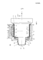
На фиг. 1 изображен опорный узел 100 для использования, например, в металлургии, содержащий валок с бочкой 11 и, по меньшей мере, одной цилиндрической шейкой 10. Шейка 10 валка без возможности проворота и, по меньшей мере, без радиального зазора установлена в выполненном цилиндрическим в соответствии с ней посадочном отверстии втулки 20. Для создания соединения с силовым замыканием без радиального зазора втулка 20 напрессована в горячем состоянии на шейку 10. Предпочтительным образом предусмотрено, что между шейкой 10 и втулкой 20 расположен, по меньшей мере, один поводковый элемент 23, например, в виде призматической шпонки или соответственно специально выполненного пазового сухаря.In FIG. 1 shows a
Внутренняя поверхность 21 втулки 20 и/или внешняя поверхность шейки 10 снабжены вогнутым контуром, называемым ниже также профилированием 40, которое выполнено, например, точением и/или шлифованием. В зоне своей вогнутости профилирование 40 имеет, если смотреть в продольном разрезе втулки 20, по меньшей мере, на отдельных участках контур в форме прямой, синусоиды, многоугольной кривой R(x) n-й степени или их комбинации. Профилирование 40 может описывать также простую параболическую кривую.The inner surface 21 of the
За счет вогнутых конфигураций профиля на втулке 20 или шейке 10 образуются углубления, которые при насаженной на шейку 10 втулке 20 в ненагруженном состоянии образуют радиально огибающую вращательно-симметричную полость 12 между втулкой 20 и шейкой 10. Полость 12 выполнена в виде кольцевой щели в смысле огибающего вращательно-симметричного полого профиля. Внешняя боковая поверхность 22 втулки 20 и боковая поверхность 13 шейки 10 выполнены, например, цилиндрическими.Due to the concave configurations of the profile on the
Может быть предусмотрено выполнение профилирования 40 на боковой поверхности 13 шейки 10, а внутренней боковой поверхности 21 втулки 20 - цилиндрической. Описанные профилирования 40 могут быть выполнены также одновременно на внутренней боковой поверхности втулки и внешней боковой поверхности шейки, преимущественно напротив друг друга. Для ограничения положения втулки 20 при надевании на шейку 10 между торцевой стороной бочки 11 валка и втулкой 20 расположено дистанционное кольцо 28 с упором 25. В качестве альтернативы бочка 11 валка может быть снабжена на торцевой стороне выступом (не показан) в качестве упора 25, который выполнен за одно целое с бочкой 11. После надевания на шейку 10 втулка 20 с помощью нажимного кольца 17 с буртиком через упорный подшипник, расположенный в качестве опции для опирания шейки 10, и гайки 18 притянута в осевом направлении x к дистанционному кольцу 28 и защищена от осевого смещения, причем шейка снабжена на своем конце для размещения кольца 17 ступичным выступом 26 и примыкающим к нему резьбовой цапфой 27 для размещения гайки 18. На фиг. 1 и 2 между кольцом 17 и гайкой 18 лишь схематично изображено внутреннее кольцо 16 упорного подшипника. От ослабления гайка 18 может быть дополнительно защищена предохранителем 19, например контргайкой.Profiling 40 may be provided on the
Глубина t профилирования 40 или величина результирующей из этой полости 12 между втулкой 20 и шейкой 10 в зависимости от максимально возникающего опорного усилия F и модуля упругости втулки 20 согласована таким образом, что объем полости 12 тем больше, чем выше максимальное опорное усилие F в нагруженном состоянии, причем деформация втулки 20 остается исключительно в упругой области. Фактическая глубина t профиля лежит в микрометровом диапазоне, предпочтительно до 1000 мкм.The profiling depth t 40 or the value resulting from this
Толщина d стенки цилиндрической втулки 20 составляет 10-75 мм без учета описанной ниже опциональной вращательно-симметричной вогнутости.The wall thickness d of the
Кроме того, может быть предусмотрена, по меньшей мере, одна подушка 50 с подшипниковой втулкой 51 для размещения втулки 20 с шейкой 10, причем между подшипниковой втулкой 51 подушки 50 и внешней боковой поверхностью 22 втулки 20 предусмотрена несущая масляная пленка 30. Это устройство называется также опорой жидкостного трения. В одном предпочтительном варианте внутренняя боковая поверхность подшипниковой втулки 51 имеет покрытие из подшипникового материала, например баббита.In addition, at least one
В другом варианте на фиг. 2 шейка 10 выполнена в форме усеченного конуса. Внутренняя боковая поверхность 21 втулки 20 выполнена ответной к идеальной линии (без профилирования) шейки 10. При этом, как сказано выше, профилирование 40 выполнено на внутренней боковой поверхности 21 втулки 20 и/или на внешней боковой поверхности 13 шейки 10.In another embodiment of FIG. 2
В этом варианте втулка 20 надевается на шейку 10, пока не исчезнет радиальный зазор между ними. Затем, как описано выше со ссылкой на фиг. 1, втулка 20 напрягается и предохраняется от смещения.In this embodiment, the
Чтобы обеспечить стабильную посадку втулки 20 на шейке 10 без радиального зазора, втулка 20 и шейка 10 имеют в осевом направлении рядом с обеих сторон полости примыкающие друг к другу поверхности прилегания 14.To ensure a stable fit of the
Толщина d стенки цилиндрической втулки 20 составляет на ее тонком конце 10-75 мм.The wall thickness d of the
Между втулкой 20 и шейкой 10 дополнительно расположена смазочная пленка 31 во избежание холодной микросварки в результате микротрения. Профилирования 40 шейки 10 и втулки 20 в этом варианте выполнены так же, как и в описании фиг. 1.Between the
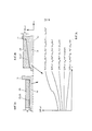
На фиг. 3а и 3b изображен опорный узел 100 с валком и, по меньшей мере, одной втулкой 20 для лишенного зазора и размещения без возможности проворота одной из шеек 10. При этом боковая поверхность 13 шейки 10 и внутренняя боковая поверхность 21 втулки 20 могут быть выполнены в форме цилиндра или усеченного конуса, причем поверхности 13, 21 выполнены ответными друг другу и примыкают друг к другу без радиального зазора.In FIG. 3a and 3b, there is shown a
На фиг. 3с профилирования 40 внутренней боковой поверхности 21 втулки 20 и/или боковой поверхности 13 шейки 10 описывают различные возможности математических функций R(x) n-й степени, которые в зависимости от нагрузки могут найти применение также в комбинации с другими профилированиями. Чтобы обеспечить равномерный, лишенный кромок переход в случае комбинированных между собой участков профиля, профилирование 40 в переходной зоне между двумя соседними участками профиля выполнено непрерывным и дифференцируемым. Следует сказать, что изображенные на фиг. 3с кривые не описывают фактически реализуемые на практике профилирования. Показанное множество участков кривых или профиля служит лишь для схематичной иллюстрации различных возможных вариантов профиля.In FIG. 3c, profiling 40 of the inner side surface 21 of the
Принцип действияOperating principle
Принцип действия изобретения более подробно описан ниже со ссылкой на фиг. 4.The principle of operation of the invention is described in more detail below with reference to FIG. four.
За счет возникающей в результате профилирования 40 вращательно-симметричной полости 12 между втулкой 20 и шейкой 10 между ними возникает увеличенное свободное пространство, в которое в месте силового воздействия может расширяться втулка 20.Due to the rotationally
Конкретно в режиме прокатки в прокатной клети к верхнему (опорному) валку прикладывается прокатное усилие Fw, направленное, по меньшей мере, в основном, вертикально вверх, тогда как в то же время к нижнему (опорному) валку прикладывается прокатное усилие Fw, направленное, по меньшей мере, в основном, вертикально вниз. Эти прокатные усилия передаются с бочек валков соответственно наполовину на шейки валков, в результате чего шейки давят в верхней подушке вверх, а в нижней подушке - вниз.Specifically, in the rolling mode in the rolling stand, the rolling force F w is applied to the upper (support) roll, directed at least mainly vertically upwards, while at the same time, the rolling force F w , directed to the lower (support) roll, is applied at least mostly vertically down. These rolling forces are transferred from the roll barrels to half respectively on the roll necks, as a result of which the neck presses up in the upper cushion and down in the lower cushion.
Прокатные усилия передаются в соответствии с функциональной цепью от шейки валка дальше через втулку шейки, несущую масляную пленку между втулкой шейки и подшипниковой втулкой на подушку. От подушки прокатные усилия отводятся в прокатную клеть, в которой подушка установлена.The rolling forces are transferred in accordance with the functional chain from the roll neck further through the neck sleeve, which carries the oil film between the neck sleeve and the bearing sleeve to the pillow. From the pillow, the rolling forces are diverted to the rolling stand in which the pillow is installed.
Подушку и установленную в ней подшипниковую втулку следует в идеальном случае рассматривать как неподатливые и несжимаемые по отношению к прокатным усилиям. Это значит, что подушка и подшипниковая втулка полностью улавливают действующие на них соответственно половинные прокатные усилия Fw/2 (действие), тогда как они противопоставляют соответственно такие же по значению, однако противоположно направленные усилия FL на опоре (противодействие).The pillow and the bearing sleeve installed in it should ideally be considered as unyielding and incompressible with respect to the rolling forces. This means that the pillow and bearing sleeve fully capture the corresponding half rolling forces F w / 2 (action) acting on them, while they contrast accordingly the same in value, however, oppositely directed forces F L on the support (reaction).
Уже при нагружении шейки 10 валка в режиме прокатки небольшим прокатным усилием Fw шейка 10 вместе с втулкой 20 давит в направлении прокатного усилия Fw на несущую масляную пленку 30, которая давит на подшипниковую втулку 51 и подушку (фиг. 2). При этом втулка 20 ударяется о несжимаемую несущую масляную пленку 30, которой неподатливые подшипниковая втулка 51 и подушка 50 не дают отклониться в направлении прокатного усилия. В результате противодействующее усилие FL на опоре не дает втулке 20 отклониться в направлении прокатного усилия.Even when loading the
Сама втулка 20 в сочетании с полостью 12 в направлении шейки 10 является самым слабым звеном в описанной выше функциональной цепи (прокатного) усилия.The
Поскольку втулка 20 не может избегнуть прокатного усилия, в случае нагрузки в режиме прокатки происходит упругая деформация втулки 20. За счет прокатного усилия Fw/2 или встречно направленного усилия FL на опоре втулка 20 деформируется внутрь первоначальной полости 12 и при этом уплощается. Уплощение происходит максимально до тех пор, пока втулка 20 не будет давить на шейку 10 и не будет поддерживаться ею. Втулка 20 локально упруго приспосабливается к профилированию 40 шейки 10 и после снятия нагрузки снова деформируется в первоначальное состояние. За счет уплощения увеличивается оказывающая давление поверхность между втулкой 20 и подшипниковой втулкой 51. Между обеими втулками 20, 51 расположена несущая масляная пленка 30, которая образует так называемую гидродинамическую опору жидкостного трения. За счет увеличения оказывающей давление поверхности опорный узел приводит к повышению несущей способности гидродинамической опоры жидкостного трения между втулками 20, 51.Since the
В действительности прокатное усилие или опорное усилие действует не точечно или линейно, а в виде так называемой «силовой горы». Последняя имеет плоскую протяженность в направлении периферии и в осевом направлении. За счет уплощения втулки шейки и связанного с этим увеличения оказывающей давление поверхности достигается заметное повышение несущей способности опорного узла для плоско протяженной «силовой горы».In fact, the rolling force or the supporting force acts not pointwise or linearly, but in the form of the so-called “power mountain”. The latter has a flat extent in the direction of the periphery and in the axial direction. Due to the flattening of the neck sleeve and the associated increase in the pressure surface, a noticeable increase in the bearing capacity of the support unit for a flatly extended “power mountain” is achieved.
Опорный узел обладает также заметно большей несущей способностью по сравнению с опорным узлом, втулка которого еще в ненагруженном состоянии соединена с шейкой валка с силовым замыканием с натягом, например посредством горячей посадки. Необходимое для упругого уплощения втулки шейки силовое воздействие вследствие полости ниже, чем в конструкциях с натягом между втулкой и шейкой. В конструкциях с натягом требуются большие усилия для реализации такой же деформации втулки шейки.The support unit also has a markedly greater load-bearing capacity compared to the support unit, the sleeve of which is still in an unloaded state connected to the neck of the roll with a force short circuit, for example by means of a hot fit. The force required for elastic flattening of the neck sleeve due to the cavity is lower than in structures with an interference fit between the sleeve and the neck. In interference fit constructions, great efforts are required to realize the same deformation of the neck sleeve.
Другими словами, благодаря относительно небольшой толщине стенки втулки 20 деформация под нагрузкой на внутренней боковой поверхности 21 втулки 20 происходит без изменений, т.е. как и на ее внешней боковой поверхности 22, что приводит к увеличению/расширению противодействующей силовому воздействию поверхности давления между втулкой 20 и подшипниковой втулкой 51. Это, в свою очередь, приводит к более равномерному распределению давления смазочной пленки, так что воспринимается и может шире распределяться большее усилие, в результате чего пиковое давление в несущей масляной пленке 30 не превышает предельных значений материала подшипниковой втулки или ее вкладыша. Следовательно, предложенный узел приводит к повышению несущей способности гидродинамической опоры жидкостного трения между втулками 20, 51.In other words, due to the relatively small wall thickness of the
Перечень ссылочных позиций List of Reference Items
100 - опорный узел100 - reference node
10 - шейка валка10 - roll neck
11 - бочка валка11 - roll barrel
12 - полость12 - cavity
13 - боковая поверхность шейки валка13 - lateral surface of the neck of the roll
14 - плоская поверхность прилегания14 - flat contact surface
15 - средняя ось15 - middle axis
16 - внутреннее кольцо упорного подшипника16 - an internal ring of the persistent bearing
17 - нажимное кольцо с буртиком17 - pressure ring with shoulder
18 - гайка18 - nut
19 - контргайка19 - locknut
20 - втулка шейки20 - neck sleeve
21 - внутренняя боковая поверхность втулки шейки21 - inner side surface of the neck sleeve
22 - внешняя боковая поверхность втулки шейки22 - the outer side surface of the neck sleeve
23 - поводковый элемент23 - lead element
25 - упор25 - emphasis
26 - ступичный выступ26 - hub ledge
27 - резьбовая цапфа27 - threaded pin
28 - дистанционное кольцо28 - distance ring
30 - несущая масляная пленка30 - carrier oil film
31 - смазочная пленка31 - lubricating film
40 - профилирование40 - profiling
44 - распределение давления - уровень техники44 - pressure distribution - prior art
46 - оптимизированное распределение давления46 - optimized pressure distribution
50 - подушка50 - pillow
51 - подшипниковая втулка51 - bearing sleeve
R(x) - профилирование в качестве математической функцииR (x) - profiling as a mathematical function
х - координата в осевом направленииx - coordinate in the axial direction
Fw - прокатное усилиеF w - rolling force
FL - опорное усилиеF L - reference force
t - глубина профиляt - profile depth
d - толщина стенки втулки шейкиd - wall thickness of the neck sleeve
Claims (8)
Applications Claiming Priority (3)
| Application Number | Priority Date | Filing Date | Title |
|---|---|---|---|
| DE102012209831.3 | 2012-06-12 | ||
| DE102012209831A DE102012209831A1 (en) | 2012-06-12 | 2012-06-12 | roll arrangement |
| PCT/EP2013/061822 WO2013186142A1 (en) | 2012-06-12 | 2013-06-07 | Roll arrangement |
Publications (2)
| Publication Number | Publication Date |
|---|---|
| RU2014153914A RU2014153914A (en) | 2016-07-27 |
| RU2604545C2 true RU2604545C2 (en) | 2016-12-10 |
Family
ID=48577762
Family Applications (1)
| Application Number | Title | Priority Date | Filing Date |
|---|---|---|---|
| RU2014153914/02A RU2604545C2 (en) | 2012-06-12 | 2013-06-07 | Support assembly |
Country Status (9)
| Country | Link |
|---|---|
| US (1) | US9180501B1 (en) |
| EP (1) | EP2858768B1 (en) |
| JP (1) | JP5823654B2 (en) |
| KR (1) | KR101700210B1 (en) |
| CN (1) | CN104540608B (en) |
| BR (1) | BR112014031004A2 (en) |
| DE (1) | DE102012209831A1 (en) |
| RU (1) | RU2604545C2 (en) |
| WO (1) | WO2013186142A1 (en) |
Families Citing this family (2)
| Publication number | Priority date | Publication date | Assignee | Title |
|---|---|---|---|---|
| DE102012209828A1 (en) * | 2012-06-12 | 2013-12-12 | Sms Siemag Ag | roll arrangement |
| DE102017216547A1 (en) | 2017-09-19 | 2019-03-21 | Sms Group Gmbh | rolling mill |
Citations (4)
| Publication number | Priority date | Publication date | Assignee | Title |
|---|---|---|---|---|
| US2955002A (en) * | 1957-12-26 | 1960-10-04 | Morgan Construction Co | Bearing |
| SU1210928A1 (en) * | 1984-07-30 | 1986-02-15 | Всесоюзный Ордена Ленина Научно-Исследовательский И Проектно-Конструкторский Институт Металлургического Машиностроения "Внииметмаш" | Bearing support for rolling mill roll |
| RU2218221C2 (en) * | 1998-04-15 | 2003-12-10 | Смс Шлёманн-Зимаг Акциенгезелльшафт | Roll mill stand |
| RU2238447C1 (en) * | 2002-01-23 | 2004-10-20 | Морган Констракшн Компани | Insert of bearing with oil film and method of its making |
Family Cites Families (14)
| Publication number | Priority date | Publication date | Assignee | Title |
|---|---|---|---|---|
| US4159152A (en) | 1977-10-11 | 1979-06-26 | Morgan Construction Company | Means for lubricating the roll neck/sleeve interface of an oil film bearing |
| JPS5893508A (en) * | 1981-11-30 | 1983-06-03 | Mitsubishi Heavy Ind Ltd | Controlling roll for deflection |
| DE3150496A1 (en) * | 1981-12-19 | 1983-11-24 | Mannesmann AG, 4000 Düsseldorf | OIL FILM BEARING |
| US4772137A (en) | 1987-03-30 | 1988-09-20 | Morgan Construction Company | Oil film bearing and bushing |
| US4944609A (en) | 1987-03-30 | 1990-07-31 | Morgan Construction Company | Oil film bearing and bushing |
| US5934131A (en) * | 1998-08-10 | 1999-08-10 | Morgan Construction Company | Overhung roll assembly |
| US6149309A (en) * | 1999-07-13 | 2000-11-21 | Morgan Construction Company | Bushing for oil film bearing |
| US6468194B2 (en) | 2000-12-08 | 2002-10-22 | Morgan Construction Company | Sleeve for rolling mill oil film bearing |
| DE10336894A1 (en) | 2003-08-08 | 2005-03-10 | Sms Demag Ag | Oil film bearing for roll neck with hydrostatic support |
| US7380431B2 (en) * | 2005-07-18 | 2008-06-03 | Morgan Construction Company | Oil film bearing with compact hydraulic mount |
| DE102006016714A1 (en) * | 2006-04-08 | 2007-10-11 | Sms Demag Ag | Chock for receiving a roll neck |
| US7857522B2 (en) * | 2007-01-31 | 2010-12-28 | Siemens Industry, Inc. | Rolling mill oil film bearing |
| US8246250B2 (en) * | 2008-01-11 | 2012-08-21 | Sms Siemag Aktiengesellschaft | Bearing arrangement |
| US20110075956A1 (en) * | 2009-09-28 | 2011-03-31 | Morgan Construction Company | Sleeve for Oil Film Bearing |
-
2012
- 2012-06-12 DE DE102012209831A patent/DE102012209831A1/en not_active Withdrawn
-
2013
- 2013-06-07 WO PCT/EP2013/061822 patent/WO2013186142A1/en active Application Filing
- 2013-06-07 RU RU2014153914/02A patent/RU2604545C2/en not_active IP Right Cessation
- 2013-06-07 CN CN201380042700.0A patent/CN104540608B/en active Active
- 2013-06-07 JP JP2015516567A patent/JP5823654B2/en active Active
- 2013-06-07 BR BR112014031004A patent/BR112014031004A2/en not_active Application Discontinuation
- 2013-06-07 US US14/406,763 patent/US9180501B1/en active Active
- 2013-06-07 EP EP13727613.5A patent/EP2858768B1/en active Active
- 2013-06-07 KR KR1020157000469A patent/KR101700210B1/en active IP Right Grant
Patent Citations (4)
| Publication number | Priority date | Publication date | Assignee | Title |
|---|---|---|---|---|
| US2955002A (en) * | 1957-12-26 | 1960-10-04 | Morgan Construction Co | Bearing |
| SU1210928A1 (en) * | 1984-07-30 | 1986-02-15 | Всесоюзный Ордена Ленина Научно-Исследовательский И Проектно-Конструкторский Институт Металлургического Машиностроения "Внииметмаш" | Bearing support for rolling mill roll |
| RU2218221C2 (en) * | 1998-04-15 | 2003-12-10 | Смс Шлёманн-Зимаг Акциенгезелльшафт | Roll mill stand |
| RU2238447C1 (en) * | 2002-01-23 | 2004-10-20 | Морган Констракшн Компани | Insert of bearing with oil film and method of its making |
Also Published As
| Publication number | Publication date |
|---|---|
| DE102012209831A1 (en) | 2013-12-12 |
| WO2013186142A1 (en) | 2013-12-19 |
| US9180501B1 (en) | 2015-11-10 |
| CN104540608B (en) | 2017-01-18 |
| KR20150023682A (en) | 2015-03-05 |
| EP2858768A1 (en) | 2015-04-15 |
| CN104540608A (en) | 2015-04-22 |
| JP2015519207A (en) | 2015-07-09 |
| KR101700210B1 (en) | 2017-01-26 |
| RU2014153914A (en) | 2016-07-27 |
| US20150343504A1 (en) | 2015-12-03 |
| BR112014031004A2 (en) | 2017-08-08 |
| EP2858768B1 (en) | 2016-09-14 |
| JP5823654B2 (en) | 2015-11-25 |
Similar Documents
| Publication | Publication Date | Title |
|---|---|---|
| RU2603403C2 (en) | Forming roll support assembly | |
| CN104880315A (en) | High speed rolling bearing dynamic performance testing machine using tilting-pad bearing to support | |
| RU2604545C2 (en) | Support assembly | |
| US8246250B2 (en) | Bearing arrangement | |
| US8801293B2 (en) | Mounting sleeve for mounting a ring member on a shaft and a bearing assembly incorporating such a mounting sleeve | |
| EP2921726A1 (en) | Friction minimized sliding bearing arrangement | |
| JP2015519206A5 (en) | ||
| CN202851714U (en) | Sliding bearing cross package of entire fork cross axle universal coupling | |
| CA2483638C (en) | Device for controlling the contact pressure of contact rolls | |
| JP6275255B2 (en) | Roll assembly for rolls in rolling equipment | |
| KR102347347B1 (en) | roll stand | |
| RU2365441C2 (en) | Method and device for creation of preload in conical roller bearings of mill roller | |
| KR101205277B1 (en) | Multipart roll | |
| CN214661562U (en) | Lubrication groove for machine tool spindle bearing | |
| CN103982546A (en) | Multilayer wear-resistant automobile balance bearing | |
| RU2826301C2 (en) | Trunnion bushing as part of bearing with oil film | |
| KR20230173160A (en) | Neck bushing as part of oil film bearing | |
| RU2217252C2 (en) | Sleeve-insert of liquid friction bearing assembly of support unit of rolling roll and method for making it | |
| RU25538U1 (en) | POWER CYLINDER | |
| RU2630137C1 (en) | Mill roll liquid friction bearing trunnion bush | |
| Woollen | The Development of Back-up Roll Bearings for Strip Mills | |
| CN103982549A (en) | Multilayered composite wear-resistant balance bearing |
Legal Events
| Date | Code | Title | Description |
|---|---|---|---|
| MM4A | The patent is invalid due to non-payment of fees |
Effective date: 20190608 |