RU2598503C2 - Chemical looping combustion method with removal of ash and fines in reduction area, and facility using such method - Google Patents
Chemical looping combustion method with removal of ash and fines in reduction area, and facility using such method Download PDFInfo
- Publication number
- RU2598503C2 RU2598503C2 RU2014115717/06A RU2014115717A RU2598503C2 RU 2598503 C2 RU2598503 C2 RU 2598503C2 RU 2014115717/06 A RU2014115717/06 A RU 2014115717/06A RU 2014115717 A RU2014115717 A RU 2014115717A RU 2598503 C2 RU2598503 C2 RU 2598503C2
- Authority
- RU
- Russia
- Prior art keywords
- particles
- zone
- stream
- separation
- oxygen carrier
- Prior art date
Links
- 238000000034 method Methods 0.000 title claims abstract description 42
- 239000000126 substance Substances 0.000 title claims abstract description 38
- 238000009841 combustion method Methods 0.000 title description 3
- 239000002245 particle Substances 0.000 claims abstract description 255
- 238000000926 separation method Methods 0.000 claims abstract description 103
- 239000002956 ash Substances 0.000 claims abstract description 91
- 229910052760 oxygen Inorganic materials 0.000 claims abstract description 82
- 239000001301 oxygen Substances 0.000 claims abstract description 80
- QVGXLLKOCUKJST-UHFFFAOYSA-N atomic oxygen Chemical compound [O] QVGXLLKOCUKJST-UHFFFAOYSA-N 0.000 claims abstract description 79
- 238000006243 chemical reaction Methods 0.000 claims abstract description 77
- 238000002485 combustion reaction Methods 0.000 claims abstract description 70
- 239000007789 gas Substances 0.000 claims abstract description 63
- 239000012876 carrier material Substances 0.000 claims abstract description 49
- 239000007787 solid Substances 0.000 claims abstract description 47
- 239000010881 fly ash Substances 0.000 claims abstract description 31
- 239000000203 mixture Substances 0.000 claims abstract description 29
- 238000007254 oxidation reaction Methods 0.000 claims abstract description 27
- 230000003647 oxidation Effects 0.000 claims abstract description 24
- 229930195733 hydrocarbon Natural products 0.000 claims abstract description 13
- 150000002430 hydrocarbons Chemical class 0.000 claims abstract description 13
- 239000004215 Carbon black (E152) Substances 0.000 claims abstract description 9
- 238000005243 fluidization Methods 0.000 claims description 47
- 239000003245 coal Substances 0.000 claims description 45
- 238000010908 decantation Methods 0.000 claims description 35
- 239000000428 dust Substances 0.000 claims description 34
- 239000003517 fume Substances 0.000 claims description 34
- 239000004449 solid propellant Substances 0.000 claims description 22
- 235000002918 Fraxinus excelsior Nutrition 0.000 claims description 21
- 238000011084 recovery Methods 0.000 claims description 16
- 238000009826 distribution Methods 0.000 claims description 14
- 230000008021 deposition Effects 0.000 claims description 11
- 238000009434 installation Methods 0.000 claims description 11
- 239000002699 waste material Substances 0.000 claims description 11
- 238000004140 cleaning Methods 0.000 claims description 10
- 239000010795 gaseous waste Substances 0.000 claims description 10
- 239000000463 material Substances 0.000 claims description 6
- 230000033116 oxidation-reduction process Effects 0.000 claims description 6
- 238000004064 recycling Methods 0.000 claims description 6
- 239000000779 smoke Substances 0.000 claims description 5
- 238000000605 extraction Methods 0.000 claims description 4
- 239000002006 petroleum coke Substances 0.000 claims description 3
- 239000002028 Biomass Substances 0.000 claims description 2
- 239000010426 asphalt Substances 0.000 claims description 2
- 239000000571 coke Substances 0.000 claims description 2
- 239000010791 domestic waste Substances 0.000 claims description 2
- UGFAIRIUMAVXCW-UHFFFAOYSA-N Carbon monoxide Chemical compound [O+]#[C-] UGFAIRIUMAVXCW-UHFFFAOYSA-N 0.000 abstract description 3
- 230000000694 effects Effects 0.000 abstract description 2
- 239000000945 filler Substances 0.000 abstract 5
- 239000003546 flue gas Substances 0.000 abstract 2
- 238000007599 discharging Methods 0.000 abstract 1
- 239000000383 hazardous chemical Substances 0.000 abstract 1
- 239000002912 waste gas Substances 0.000 abstract 1
- 239000000446 fuel Substances 0.000 description 50
- 229910044991 metal oxide Inorganic materials 0.000 description 46
- 150000004706 metal oxides Chemical class 0.000 description 44
- 238000002309 gasification Methods 0.000 description 15
- XLYOFNOQVPJJNP-UHFFFAOYSA-N water Substances O XLYOFNOQVPJJNP-UHFFFAOYSA-N 0.000 description 11
- 229910052739 hydrogen Inorganic materials 0.000 description 7
- 239000000047 product Substances 0.000 description 7
- 238000005273 aeration Methods 0.000 description 6
- 229910002091 carbon monoxide Inorganic materials 0.000 description 6
- 230000001590 oxidative effect Effects 0.000 description 6
- 239000001257 hydrogen Substances 0.000 description 5
- JTJMJGYZQZDUJJ-UHFFFAOYSA-N phencyclidine Chemical class C1CCCCN1C1(C=2C=CC=CC=2)CCCCC1 JTJMJGYZQZDUJJ-UHFFFAOYSA-N 0.000 description 5
- CURLTUGMZLYLDI-UHFFFAOYSA-N Carbon dioxide Chemical compound O=C=O CURLTUGMZLYLDI-UHFFFAOYSA-N 0.000 description 4
- 238000005299 abrasion Methods 0.000 description 4
- 238000004458 analytical method Methods 0.000 description 4
- 238000004519 manufacturing process Methods 0.000 description 4
- UFHFLCQGNIYNRP-UHFFFAOYSA-N Hydrogen Chemical compound [H][H] UFHFLCQGNIYNRP-UHFFFAOYSA-N 0.000 description 3
- 230000006835 compression Effects 0.000 description 3
- 238000007906 compression Methods 0.000 description 3
- 238000009833 condensation Methods 0.000 description 3
- 230000005494 condensation Effects 0.000 description 3
- 239000002923 metal particle Substances 0.000 description 3
- OKTJSMMVPCPJKN-UHFFFAOYSA-N Carbon Chemical group [C] OKTJSMMVPCPJKN-UHFFFAOYSA-N 0.000 description 2
- VYPSYNLAJGMNEJ-UHFFFAOYSA-N Silicium dioxide Chemical compound O=[Si]=O VYPSYNLAJGMNEJ-UHFFFAOYSA-N 0.000 description 2
- 238000009825 accumulation Methods 0.000 description 2
- 238000013459 approach Methods 0.000 description 2
- 230000015572 biosynthetic process Effects 0.000 description 2
- 229910052799 carbon Inorganic materials 0.000 description 2
- 229910002092 carbon dioxide Inorganic materials 0.000 description 2
- 239000001569 carbon dioxide Substances 0.000 description 2
- 239000010419 fine particle Substances 0.000 description 2
- 150000002431 hydrogen Chemical group 0.000 description 2
- 238000011068 loading method Methods 0.000 description 2
- 150000002894 organic compounds Chemical class 0.000 description 2
- 230000001105 regulatory effect Effects 0.000 description 2
- 239000003039 volatile agent Substances 0.000 description 2
- 229910018072 Al 2 O 3 Inorganic materials 0.000 description 1
- 229910004298 SiO 2 Inorganic materials 0.000 description 1
- NINIDFKCEFEMDL-UHFFFAOYSA-N Sulfur Chemical compound [S] NINIDFKCEFEMDL-UHFFFAOYSA-N 0.000 description 1
- 229910010413 TiO 2 Inorganic materials 0.000 description 1
- 230000001133 acceleration Effects 0.000 description 1
- 238000005054 agglomeration Methods 0.000 description 1
- 230000002776 aggregation Effects 0.000 description 1
- PNEYBMLMFCGWSK-UHFFFAOYSA-N aluminium oxide Inorganic materials [O-2].[O-2].[O-2].[Al+3].[Al+3] PNEYBMLMFCGWSK-UHFFFAOYSA-N 0.000 description 1
- 238000009835 boiling Methods 0.000 description 1
- 239000000969 carrier Substances 0.000 description 1
- 239000012159 carrier gas Substances 0.000 description 1
- 239000000567 combustion gas Substances 0.000 description 1
- 238000004891 communication Methods 0.000 description 1
- 239000000356 contaminant Substances 0.000 description 1
- 230000001276 controlling effect Effects 0.000 description 1
- 230000006378 damage Effects 0.000 description 1
- 238000013461 design Methods 0.000 description 1
- 238000010790 dilution Methods 0.000 description 1
- 239000012895 dilution Substances 0.000 description 1
- 230000005611 electricity Effects 0.000 description 1
- 238000010438 heat treatment Methods 0.000 description 1
- 239000004615 ingredient Substances 0.000 description 1
- 238000002347 injection Methods 0.000 description 1
- 239000007924 injection Substances 0.000 description 1
- 229910052500 inorganic mineral Inorganic materials 0.000 description 1
- 239000007788 liquid Substances 0.000 description 1
- 230000007246 mechanism Effects 0.000 description 1
- 230000008018 melting Effects 0.000 description 1
- 238000002844 melting Methods 0.000 description 1
- 239000011707 mineral Substances 0.000 description 1
- 150000002926 oxygen Chemical class 0.000 description 1
- 238000000746 purification Methods 0.000 description 1
- 230000035484 reaction time Effects 0.000 description 1
- 239000000377 silicon dioxide Substances 0.000 description 1
- 238000003860 storage Methods 0.000 description 1
- 229910052717 sulfur Inorganic materials 0.000 description 1
- 239000011593 sulfur Substances 0.000 description 1
- 239000013589 supplement Substances 0.000 description 1
- 238000012546 transfer Methods 0.000 description 1
Images
Classifications
-
- F—MECHANICAL ENGINEERING; LIGHTING; HEATING; WEAPONS; BLASTING
- F23—COMBUSTION APPARATUS; COMBUSTION PROCESSES
- F23C—METHODS OR APPARATUS FOR COMBUSTION USING FLUID FUEL OR SOLID FUEL SUSPENDED IN A CARRIER GAS OR AIR
- F23C10/00—Fluidised bed combustion apparatus
- F23C10/01—Fluidised bed combustion apparatus in a fluidised bed of catalytic particles
-
- B—PERFORMING OPERATIONS; TRANSPORTING
- B01—PHYSICAL OR CHEMICAL PROCESSES OR APPARATUS IN GENERAL
- B01J—CHEMICAL OR PHYSICAL PROCESSES, e.g. CATALYSIS OR COLLOID CHEMISTRY; THEIR RELEVANT APPARATUS
- B01J8/00—Chemical or physical processes in general, conducted in the presence of fluids and solid particles; Apparatus for such processes
- B01J8/18—Chemical or physical processes in general, conducted in the presence of fluids and solid particles; Apparatus for such processes with fluidised particles
- B01J8/1818—Feeding of the fluidising gas
- B01J8/1827—Feeding of the fluidising gas the fluidising gas being a reactant
-
- B—PERFORMING OPERATIONS; TRANSPORTING
- B01—PHYSICAL OR CHEMICAL PROCESSES OR APPARATUS IN GENERAL
- B01J—CHEMICAL OR PHYSICAL PROCESSES, e.g. CATALYSIS OR COLLOID CHEMISTRY; THEIR RELEVANT APPARATUS
- B01J8/00—Chemical or physical processes in general, conducted in the presence of fluids and solid particles; Apparatus for such processes
- B01J8/18—Chemical or physical processes in general, conducted in the presence of fluids and solid particles; Apparatus for such processes with fluidised particles
- B01J8/24—Chemical or physical processes in general, conducted in the presence of fluids and solid particles; Apparatus for such processes with fluidised particles according to "fluidised-bed" technique
- B01J8/26—Chemical or physical processes in general, conducted in the presence of fluids and solid particles; Apparatus for such processes with fluidised particles according to "fluidised-bed" technique with two or more fluidised beds, e.g. reactor and regeneration installations
-
- B—PERFORMING OPERATIONS; TRANSPORTING
- B01—PHYSICAL OR CHEMICAL PROCESSES OR APPARATUS IN GENERAL
- B01J—CHEMICAL OR PHYSICAL PROCESSES, e.g. CATALYSIS OR COLLOID CHEMISTRY; THEIR RELEVANT APPARATUS
- B01J8/00—Chemical or physical processes in general, conducted in the presence of fluids and solid particles; Apparatus for such processes
- B01J8/18—Chemical or physical processes in general, conducted in the presence of fluids and solid particles; Apparatus for such processes with fluidised particles
- B01J8/24—Chemical or physical processes in general, conducted in the presence of fluids and solid particles; Apparatus for such processes with fluidised particles according to "fluidised-bed" technique
- B01J8/32—Chemical or physical processes in general, conducted in the presence of fluids and solid particles; Apparatus for such processes with fluidised particles according to "fluidised-bed" technique with introduction into the fluidised bed of more than one kind of moving particles
-
- F—MECHANICAL ENGINEERING; LIGHTING; HEATING; WEAPONS; BLASTING
- F23—COMBUSTION APPARATUS; COMBUSTION PROCESSES
- F23C—METHODS OR APPARATUS FOR COMBUSTION USING FLUID FUEL OR SOLID FUEL SUSPENDED IN A CARRIER GAS OR AIR
- F23C10/00—Fluidised bed combustion apparatus
- F23C10/005—Fluidised bed combustion apparatus comprising two or more beds
-
- F—MECHANICAL ENGINEERING; LIGHTING; HEATING; WEAPONS; BLASTING
- F23—COMBUSTION APPARATUS; COMBUSTION PROCESSES
- F23C—METHODS OR APPARATUS FOR COMBUSTION USING FLUID FUEL OR SOLID FUEL SUSPENDED IN A CARRIER GAS OR AIR
- F23C10/00—Fluidised bed combustion apparatus
- F23C10/02—Fluidised bed combustion apparatus with means specially adapted for achieving or promoting a circulating movement of particles within the bed or for a recirculation of particles entrained from the bed
- F23C10/04—Fluidised bed combustion apparatus with means specially adapted for achieving or promoting a circulating movement of particles within the bed or for a recirculation of particles entrained from the bed the particles being circulated to a section, e.g. a heat-exchange section or a return duct, at least partially shielded from the combustion zone, before being reintroduced into the combustion zone
- F23C10/08—Fluidised bed combustion apparatus with means specially adapted for achieving or promoting a circulating movement of particles within the bed or for a recirculation of particles entrained from the bed the particles being circulated to a section, e.g. a heat-exchange section or a return duct, at least partially shielded from the combustion zone, before being reintroduced into the combustion zone characterised by the arrangement of separation apparatus, e.g. cyclones, for separating particles from the flue gases
- F23C10/10—Fluidised bed combustion apparatus with means specially adapted for achieving or promoting a circulating movement of particles within the bed or for a recirculation of particles entrained from the bed the particles being circulated to a section, e.g. a heat-exchange section or a return duct, at least partially shielded from the combustion zone, before being reintroduced into the combustion zone characterised by the arrangement of separation apparatus, e.g. cyclones, for separating particles from the flue gases the separation apparatus being located outside the combustion chamber
-
- F—MECHANICAL ENGINEERING; LIGHTING; HEATING; WEAPONS; BLASTING
- F23—COMBUSTION APPARATUS; COMBUSTION PROCESSES
- F23C—METHODS OR APPARATUS FOR COMBUSTION USING FLUID FUEL OR SOLID FUEL SUSPENDED IN A CARRIER GAS OR AIR
- F23C10/00—Fluidised bed combustion apparatus
- F23C10/18—Details; Accessories
- F23C10/24—Devices for removal of material from the bed
-
- F—MECHANICAL ENGINEERING; LIGHTING; HEATING; WEAPONS; BLASTING
- F23—COMBUSTION APPARATUS; COMBUSTION PROCESSES
- F23C—METHODS OR APPARATUS FOR COMBUSTION USING FLUID FUEL OR SOLID FUEL SUSPENDED IN A CARRIER GAS OR AIR
- F23C99/00—Subject-matter not provided for in other groups of this subclass
-
- F—MECHANICAL ENGINEERING; LIGHTING; HEATING; WEAPONS; BLASTING
- F23—COMBUSTION APPARATUS; COMBUSTION PROCESSES
- F23J—REMOVAL OR TREATMENT OF COMBUSTION PRODUCTS OR COMBUSTION RESIDUES; FLUES
- F23J1/00—Removing ash, clinker, or slag from combustion chambers
-
- B—PERFORMING OPERATIONS; TRANSPORTING
- B01—PHYSICAL OR CHEMICAL PROCESSES OR APPARATUS IN GENERAL
- B01J—CHEMICAL OR PHYSICAL PROCESSES, e.g. CATALYSIS OR COLLOID CHEMISTRY; THEIR RELEVANT APPARATUS
- B01J2208/00—Processes carried out in the presence of solid particles; Reactors therefor
- B01J2208/00008—Controlling the process
- B01J2208/00017—Controlling the temperature
- B01J2208/00513—Controlling the temperature using inert heat absorbing solids in the bed
-
- F—MECHANICAL ENGINEERING; LIGHTING; HEATING; WEAPONS; BLASTING
- F23—COMBUSTION APPARATUS; COMBUSTION PROCESSES
- F23C—METHODS OR APPARATUS FOR COMBUSTION USING FLUID FUEL OR SOLID FUEL SUSPENDED IN A CARRIER GAS OR AIR
- F23C2900/00—Special features of, or arrangements for combustion apparatus using fluid fuels or solid fuels suspended in air; Combustion processes therefor
- F23C2900/99008—Unmixed combustion, i.e. without direct mixing of oxygen gas and fuel, but using the oxygen from a metal oxide, e.g. FeO
-
- Y—GENERAL TAGGING OF NEW TECHNOLOGICAL DEVELOPMENTS; GENERAL TAGGING OF CROSS-SECTIONAL TECHNOLOGIES SPANNING OVER SEVERAL SECTIONS OF THE IPC; TECHNICAL SUBJECTS COVERED BY FORMER USPC CROSS-REFERENCE ART COLLECTIONS [XRACs] AND DIGESTS
- Y02—TECHNOLOGIES OR APPLICATIONS FOR MITIGATION OR ADAPTATION AGAINST CLIMATE CHANGE
- Y02E—REDUCTION OF GREENHOUSE GAS [GHG] EMISSIONS, RELATED TO ENERGY GENERATION, TRANSMISSION OR DISTRIBUTION
- Y02E20/00—Combustion technologies with mitigation potential
- Y02E20/34—Indirect CO2mitigation, i.e. by acting on non CO2directly related matters of the process, e.g. pre-heating or heat recovery
Landscapes
- Engineering & Computer Science (AREA)
- Chemical & Material Sciences (AREA)
- Combustion & Propulsion (AREA)
- Mechanical Engineering (AREA)
- General Engineering & Computer Science (AREA)
- Chemical Kinetics & Catalysis (AREA)
- Organic Chemistry (AREA)
- Fluidized-Bed Combustion And Resonant Combustion (AREA)
- Devices And Processes Conducted In The Presence Of Fluids And Solid Particles (AREA)
Abstract
Description
Область техникиTechnical field
Изобретение относится к области сжигания в химическом контуре окисления-восстановления твердых углеводородных загрузок для производства энергии, синтетического газа и/или водорода.The invention relates to the field of combustion in a chemical oxidation-reduction circuit of solid hydrocarbon feeds for the production of energy, synthetic gas and / or hydrogen.
В частности, изобретение касается удаления зол, образующихся в восстановительном реакторе установки сжигания в химическом контуре.In particular, the invention relates to the removal of ash generated in a reduction reactor of a chemical combustion plant.
ТерминологияTerminology
Способ сжигания в химическом контуре или CLC: в дальнейшем тексте описания под способом CLC (Chemical Looping Combustion) следует понимать способ окисления-восстановления в контуре на активной массе. Следует отметить, что, как правило, термины «окисление» и «восстановление» применяют в отношении соответственно окисленного или восстановленного состояния активной массы. В установке сжигания в химическом контуре зона окисления является зоной, в которой масса окисления-восстановления окисляется, а зона восстановления является зоной, в которой масса окисления-восстановления восстанавливается.The method of combustion in a chemical circuit or CLC: in the further text of the description under the method of CLC (Chemical Looping Combustion) should be understood as a method of oxidation-reduction in the circuit on the active mass. It should be noted that, as a rule, the terms “oxidation” and “reduction” are used in relation to the respectively oxidized or reduced state of the active mass. In a combustion plant in a chemical circuit, an oxidation zone is a zone in which the oxidation-reduction mass is oxidized, and a reduction zone is a zone in which the oxidation-reduction mass is reduced.
Удаление летучих компонентов:Removal of volatile components:
в ходе термической обработки органические соединения теряют летучие вещества, сначала воду и диоксид углерода, жидкие и затем газообразные углеводороды, затем оксид углерода и, наконец, водород. Этот процесс называется удалением летучих компонентов. Температура удаления летучих компонентов и интенсивность явления зависят от исходного органического соединения. Так, для углей возрастающей сортности удаление летучих компонентов происходит при все более высокой температуре.during heat treatment, organic compounds lose volatile substances, first water and carbon dioxide, liquid and then gaseous hydrocarbons, then carbon monoxide and, finally, hydrogen. This process is called the removal of volatile components. The temperature of removal of volatile components and the intensity of the phenomenon depend on the starting organic compound. So, for coals of increasing grade, the removal of volatile components occurs at an increasingly high temperature.
Кипящий слой:Fluidized bed:
в дальнейшем тексте описания:in the further text of the description:
- под плотным кипящим слоем следует понимать кипящий слой, в котором доля газа εg меньше 0,9, предпочтительно меньше 0,8.- a dense fluidized bed should be understood as a fluidized bed in which the gas fraction ε g is less than 0.9, preferably less than 0.8.
- под разбавленным кипящим слоем следует понимать кипящий слой, в котором объемная доля частиц металлических оксидов меньше 10% по объему.- a dilute fluidized bed should be understood as a fluidized bed in which the volume fraction of particles of metal oxides is less than 10% by volume.
Проблематика золThe issue of evil
Для осуществления сжигания в химическом контуре используют материалы-носители кислорода, такие как металлические оксиды, которые отдают свой кислород в зоне восстановления (называемой «топливный реактор») в соответствующих рабочих условиях. После восстановления материал перемещают в зону окисления (называемую «воздушный реактор»), в которой он опять окисляется при контакте с окисляющим газом (например, таким как воздух или водяной пар).To carry out combustion in the chemical circuit, oxygen carrier materials, such as metal oxides, which give off their oxygen in the reduction zone (called the “fuel reactor”) under appropriate operating conditions are used. After reduction, the material is transferred to an oxidation zone (called an “air reactor”), in which it is again oxidized by contact with an oxidizing gas (for example, such as air or water vapor).
Как правило, в рамках способа сжигания в химическом контуре применяют одну или несколько реакционных зон, в которых осуществляют сжигание топлива (например, углеводородной загрузки) при контакте с твердым веществом-носителем кислорода, которое затем опять окисляется, по меньшей мере, в одной зоне окисления при контакте с воздухом или водяным паром, после чего его направляют в зону или зоны сжигания (или восстановления). Реакционные зоны, обеспечивающие осуществление реакция горения в химическом контуре, обычно представляют собой кипящие слои или подвижные слои.Typically, as part of a combustion method in a chemical circuit, one or more reaction zones are used in which a fuel (for example, a hydrocarbon charge) is burned in contact with a solid oxygen carrier substance, which is then oxidized again in at least one oxidation zone in contact with air or water vapor, after which it is sent to a zone or zones of combustion (or recovery). The reaction zones, providing the implementation of the combustion reaction in the chemical circuit, are usually fluidized beds or moving layers.
Сжигание в химическом контуре (CLC) твердых углеводородных загрузок является процессом, обеспечивающим, в частности, производство энергии (пар, электричество …) за счет отбора тепла, выделяемого в ходе реакций горения, с одновременным производством дымов с высоким содержанием СО2. Следовательно, можно предусмотреть улавливание СО2 после конденсации дымов и сжатия дымов. Можно также предусмотреть производство синтетического газа и даже водорода посредством управления горением и применения необходимой очистки на выходе процесса горения.Combustion of solid hydrocarbon feeds in a chemical circuit (CLC) is a process that ensures, in particular, the production of energy (steam, electricity ...) through the selection of heat generated during combustion reactions, while producing fumes with a high CO 2 content. Therefore, it is possible to provide for the capture of CO 2 after condensation of the fumes and compression of the fumes. The production of synthetic gas and even hydrogen can also be envisaged by controlling combustion and applying the necessary purification at the outlet of the combustion process.
В реакционных механизмах, связанных с сжиганием в химическом контуре в зоне восстановления, было установлено, что твердое топливо проходит через фазу газификации, которой способствует присутствие водяного пара или диоксида углерода и температура, затем газ, производимый на этапе газификации, окисляется при контакте с материалом-носителем кислорода. Если твердое топливо содержит летучие вещества, то они, по меньшей мере, частично удаляются при контакте с горячим материалом-носителем кислорода и затем окисляются этим кислородом. В случае, когда материал-носитель кислорода естественным образом высвобождает кислород в соответствии с рабочими условиями, можно также получать прямое окисление твердого топлива газообразным кислородом, высвобождаемым материалом в топливном реакторе.In the reaction mechanisms associated with burning in a chemical circuit in the reduction zone, it was found that solid fuel passes through the gasification phase, which is facilitated by the presence of water vapor or carbon dioxide and temperature, then the gas produced in the gasification stage is oxidized upon contact with the material oxygen carrier. If the solid fuel contains volatile substances, then they are at least partially removed by contact with the hot oxygen carrier material and then oxidized by this oxygen. In the case where the oxygen carrier material naturally releases oxygen in accordance with the operating conditions, direct oxidation of the solid fuel by gaseous oxygen released by the material in the fuel reactor can also be obtained.
Сжигание твердых загрузок в химическом контуре неизбежно происходит в экстремальных рабочих условиях, необходимых для осуществления реакций горения. Для обеспечения газификации топлива необходимо иметь высокие температуры, как правило, составляющие от 800 до 1100°С, предпочтительно составляющие от 850 до 1000°С. Время, необходимое для газификации, сокращается в зависимости от температуры и, как правило, составляет от 30 секунд до 30 минут. Поэтому предпочтительно осуществлять частичную газификацию, отделять от отходов и рециркулировать не газифицированный остаток топлива. Таким образом, можно добиться выхода конверсии (при газификации) за один цикл от 50 до 80% в температурном диапазоне от 850°С до 1000°С при времени реакции от 1 минуты до 10 минут, как правило, от 3 до 5 минут. Повысив частичное давление окисляющего газа (Н2О, СО2), можно сократить время газификации.The burning of solid loads in the chemical circuit inevitably occurs under extreme operating conditions necessary for the implementation of combustion reactions. To ensure gasification of fuel, it is necessary to have high temperatures, as a rule, constituting from 800 to 1100 ° C, preferably constituting from 850 to 1000 ° C. The time required for gasification is reduced depending on the temperature and, as a rule, ranges from 30 seconds to 30 minutes. Therefore, it is preferable to carry out partial gasification, separate from waste and recycle non-gasified fuel residue. Thus, it is possible to achieve conversion (during gasification) in one cycle from 50 to 80% in the temperature range from 850 ° C to 1000 ° C with a reaction time of 1 minute to 10 minutes, usually from 3 to 5 minutes. By increasing the partial pressure of the oxidizing gas (H 2 O, CO 2 ), the gasification time can be reduced.
Другой проблемой, связанной с применением сжигания в химическом контуре твердых загрузок, является образование зол. Действительно, твердые топлива характеризуются довольно высоким содержанием минеральных веществ, и после сгорания углерода и водорода образуются твердые остатки, называемые золами. В таблице 1 в качестве примера приведены результаты анализа двух углей А и В. Отмечается, что содержание зол в углях колеблется в зависимости от происхождения твердой загрузки, но в любом случае это содержание является значительным. Как правило, оно составляет 5-20% от массы сухого угля. Некоторые твердые топлива, такие как нефтяной кокс, характеризуются намного меньшим содержанием зол. Существуют также твердые топлива с более высоким содержанием зол.Another problem associated with the use of solid-state combustion in the chemical circuit is the formation of ash. Indeed, solid fuels are characterized by a rather high content of minerals, and after combustion of carbon and hydrogen, solid residues are formed, called ashes. Table 1 shows, by way of example, the results of the analysis of two coals A and B. It is noted that the ash content in the coals varies depending on the origin of the solid charge, but in any case this content is significant. As a rule, it makes up 5-20% of the mass of dry coal. Some solid fuels, such as petroleum coke, have a much lower ash content. There are also solid fuels with a higher ash content.
В основном эти золы представляют собой оксид кремния и оксид алюминия, однако они содержат также и другие ингредиенты, как показано в таблице 1.Basically, these ashes are silica and alumina, however, they also contain other ingredients, as shown in table 1.
Золы, получаемые при сжигании угля, состоят из мелких остаточных частиц. Их температура плавления колеблется в зависимости от их состава и, как правило, составляет от 1000 до 1500°С. Однако при более низких температурах, например, между 800 и 1000°С, можно наблюдать явление агломерации зольных частиц, которые начинают склеиваться. Таким образом, они могут либо слипаться между собой, либо слипаться с частицами материала-носителя кислорода. С учетом условий сжигания в химическом контуре различают два типа зол:The ash obtained by burning coal consists of fine residual particles. Their melting temperature varies depending on their composition and, as a rule, ranges from 1000 to 1500 ° C. However, at lower temperatures, for example, between 800 and 1000 ° C, one can observe the phenomenon of agglomeration of ash particles, which begin to stick together. Thus, they can either stick together, or stick together with particles of an oxygen carrier material. Given the conditions of combustion in the chemical circuit, two types of evils are distinguished:
- летучие золы: соответствуют золам, которые переносятся в топливном реакторе газообразными продуктами горения;- fly ash: correspond to ash that is transported in the fuel reactor by gaseous combustion products;
- агломерированные золы: соответствуют золам, которые слипаются между собой или с материалом-носителем кислорода и являются слишком тяжелыми, чтобы их могли переносить в топливном реакторе газообразные продукты горения.- agglomerated ashes: correspond to ashes that stick together or with an oxygen carrier material and are too heavy to be transported by the combustion gases in the fuel reactor.
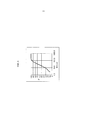
Как правило, летучие золы составляют от 50 до 99% образующихся зол, обычно от 70 до 90%. Они имеют относительно небольшой гранулометрический размер и обычно представляют собой, по меньшей мере, 25% мелких частиц размером менее 10 микрон и 90% мелких частиц размером менее 100 микрон, как показано на фиг. 3, где в качестве примера представлено типовое гранулометрическое распределение летучих зол. Как правило, средний диаметр Саутера, характеризующий гранулометрический размер летучих зол, составляет от 5 до 30 микрон и обычно приближается к 10 микронам. Плотность зерна этих зол обычно составляет от 2000 до 3000 кг/м3 и, как правило, приближается к 2500 кг/м3.As a rule, fly ashes comprise from 50 to 99% of the resulting ash, usually from 70 to 90%. They have a relatively small particle size distribution and usually represent at least 25% of fine particles with a size of less than 10 microns and 90% of small particles with a size of less than 100 microns, as shown in FIG. 3, where, as an example, a typical particle size distribution of fly ash is provided. As a rule, the average Sauter diameter, which characterizes the particle size of fly ash, is from 5 to 30 microns and usually approaches 10 microns. The grain density of these evils is usually from 2000 to 3000 kg / m 3 and, as a rule, approaches 2500 kg / m 3 .
Гранулометрический размер агломерированных частиц с трудом поддается оценке и зависит от условий процесса. Как правило, считают, что гранулометрический размер этих зол превышает 100 микрон и может достигать нескольких миллиметров.The particle size distribution of agglomerated particles is difficult to estimate and depends on the process conditions. As a rule, it is believed that the particle size distribution of these ashes exceeds 100 microns and can reach several millimeters.
В патентной заявке FR 2 850 156 описан способ сжигания в химическом контуре, согласно которому топливо измельчают перед загрузкой в восстановительный реактор, работающий в режиме подвижного копящего слоя. Меньший размер частиц твердого топлива обеспечивает более полное и более быстрое сжигание и позволяет получать почти 100% летучих зол, которые отделяются от циркулирующих оксидов. Прежде всего отделение на выходе подвижного слоя обеспечивается циклоном, затем устройством, позволяющим отделять частицы недожога от частиц металлического оксида. Таким образом, избегают перемещения недожога в зону окисления и, следовательно, выбросов СО2 в отходы окислительного реактора.Patent application FR 2 850 156 describes a method for burning in a chemical circuit, according to which the fuel is ground before loading into a reduction reactor operating in the moving storage bed mode. The smaller particle size of solid fuels provides a more complete and faster burning and allows you to get almost 100% of fly ash, which are separated from the circulating oxides. First of all, separation at the exit of the movable layer is provided by a cyclone, then a device that allows to separate the particles of underburn from the particles of metal oxide. In this way, the movement of the underburning to the oxidation zone and, consequently, the emissions of CO 2 into the waste of the oxidation reactor are avoided.
Устройство разделения содержит кипящий слой, разбавляемый водяным паром, который позволяет отделять мелкие и легкие частицы, такие как углеродсодержащий остаток, и повторно направлять этот остаток в реактор, тогда как более плотные и более крупные частицы оксидов поступают в окислительный реактор. Это устройство содержит два внутренних отсека.The separation device contains a fluidized bed, diluted with water vapor, which allows you to separate small and light particles, such as carbon-containing residue, and re-direct this residue to the reactor, while denser and larger particles of oxides enter the oxidation reactor. This device contains two internal compartments.
Кроме того, согласно FR 2 850 156, летучие золы отделяют от частиц оксидов во втором контуре, где разделитель, работающий в режиме кипящего слоя, производит разделение, при этом псевдоожиженные летучие золы направляют в бункер по пневматическому трубопроводу, а металлические оксиды извлекают после осаждения в основании реактора с кипящим слоем.In addition, according to FR 2 850 156, fly ash is separated from the oxide particles in the second circuit, where a fluidized bed separator separates, while fluidized fly ash is sent to the hopper through a pneumatic pipeline, and metal oxides are recovered after deposition in the base of the fluidized bed reactor.
Кроме того, высокие скорости газа, применяемые в восстановительном реакторе, работающем в режиме подвижного кипящего слоя, не позволяют получать время пребывания частиц, достаточное для газификации всего твердого топлива, чтобы производить затем сжигание продуктов газификации. Следовательно, необходимо производить рециркуляцию частиц недожога с их прохождением через разделитель. При этом отделение частиц оксидов является сложной операцией, так как требует дополнительной подачи большого количества газа, что приводит к большим затратам энергии.In addition, the high gas velocities used in the recovery reactor operating in the fluidized bed regime do not make it possible to obtain particle residence times sufficient for the gasification of all solid fuel to subsequently burn gasification products. Therefore, it is necessary to recirculate the particles of the burn with their passage through the separator. In this case, the separation of oxide particles is a complex operation, since it requires an additional supply of a large amount of gas, which leads to a large expenditure of energy.
Кроме того, по причине слишком короткого времени пребывания трудно осуществить полное сжигание, и дымы содержат большие количества СО и Н2, что требует наличия зоны дожигания на выходе процесса.In addition, because of the too short residence time, it is difficult to completely burn, and the fumes contain large amounts of CO and H 2 , which requires a afterburning zone at the process outlet.
В диссертации N.Berguerand “Design and Operation of a 10 kWth Chemical-Looping Combustor for Solid Fuels”, ISBN 978-91-7385-329-3 описано устройство, позволяющее производить сжигание угля с применением химического контура.N. Berguerand's dissertation, “Design and Operation of a 10 kWth Chemical-Looping Combustor for Solid Fuels”, ISBN 978-91-7385-329-3, describes a device that allows the combustion of coal using a chemical circuit.
Это устройство содержит окислительный реактор, использующий металлические частицы, циклон, обеспечивающий разделение частиц и воздуха, обедненного после окисления, кипящий слой, питаемый окисленными металлическими частицами через обратное колено, расположенное под циклоном, в котором происходит восстановление металлического оксида посредством сжигания угля. Уголь подают в верхнюю часть кипящего слоя в разбавленную фазу. В восстановительном реакторе сжигание угля происходит постепенно: частицы угля начинают опускаться противотоком по отношению к газам псевдоожижения, и происходит удаление летучих компонентов в разбавленной фазе, в которой металлические оксиды присутствуют лишь в незначительном количестве. Большое время пребывания позволяет газифицировать уголь и получать газообразные продукты сгорания, содержащие большие количества оксида углерода и водорода, которые переходят в разбавленную фазу.This device contains an oxidizing reactor using metal particles, a cyclone that separates the particles and air depleted after oxidation, a fluidized bed fed by oxidized metal particles through the back of the elbow, located under the cyclone, in which the metal oxide is reduced by burning coal. Coal is fed to the top of the fluidized bed in the diluted phase. In a reduction reactor, coal combustion occurs gradually: coal particles begin to descend in countercurrent with respect to fluidization gases, and volatile components are removed in a dilute phase in which only a small amount of metal oxides is present. The long residence time allows gasification of coal and the production of gaseous products of combustion containing large amounts of carbon monoxide and hydrogen, which pass into the diluted phase.
В плотной фазе реактора скорости псевдоожижения являются низкими, как правило от 5 до 30 см/с, что не позволяет увлекать существенные количества металлических оксидов в разбавленной фазе, которые могли бы способствовать сжиганию газов, таких как СО, Н2, или улетучивающихся углеводородов, удаляемых из зоны разбавления. Поэтому отходы восстановительного реактора содержат большие количества СО и углеводородов (НС), превышающие несколько процентов по объему. Следовательно, КПД сжигания является низким, и тоже необходимо наличие зоны дожигания для завершения сжигания.In the dense phase of the reactor, the fluidization rates are low, usually from 5 to 30 cm / s, which does not allow to entrain significant amounts of metal oxides in the diluted phase, which could contribute to the combustion of gases such as CO, H 2 , or volatile hydrocarbons removed from the dilution zone. Therefore, the waste from the reduction reactor contains large amounts of CO and hydrocarbons (HC), exceeding several percent by volume. Therefore, the combustion efficiency is low, and afterburning zone is also necessary to complete the combustion.
Кроме того, согласно этому документу, восстановительный реактор оборудован разделителем частиц, помещенным в плотную фазу, что требует добавления дополнительного газа для реализации разделения.In addition, according to this document, the reduction reactor is equipped with a particle separator placed in a dense phase, which requires the addition of additional gas to implement the separation.
В этой системе не предусмотрено специального устройства, обеспечивающего отделение и удаление зол, образующихся при сжигании твердых загрузок.This system does not provide a special device for the separation and removal of ash generated during the burning of solid loads.
Для устранения недостатков двух вышеуказанных систем заявители разработали усовершенствованный способ сжигания в химическом контуре, который даже при наличии крупных частиц топлива обеспечивает полное сжигание твердой загрузки и сведение к минимуму количества рециркулируемой твердой загрузки, что позволяет максимизировать энергетический КПД способа. Этот способ сжигания в соответствии с изобретением позволяет улавливать не менее 90% СО2, выделяемого при сжигании, в дымах непосредственно на выходе реактора сжигания, при этом степень улавливания определяют как отношение количества СО2 в дымах, выходящих из реактора сжигания, к количеству СО2, получаемому при способе сжигания в химическом контуре.To eliminate the shortcomings of the two above systems, the applicants have developed an improved method of combustion in the chemical circuit, which even in the presence of large particles of fuel ensures complete combustion of the solid charge and minimizes the amount of recycled solid load, which allows to maximize the energy efficiency of the method. This method of combustion in accordance with the invention allows capturing at least 90% of the CO 2 emitted during combustion in the fumes directly at the outlet of the combustion reactor, while the degree of capture is defined as the ratio of the amount of CO 2 in the fumes exiting the combustion reactor to the amount of CO 2 obtained by the method of combustion in a chemical circuit.
На выходе способа сжигания молярное соотношение СО/СО2 дымов на выходе циклонов меньше 0,05, и соотношение Н2/Н2О меньше 0,05. Этого достигают, с одной стороны, благодаря оптимизации первоначального контакта между частицами-носителями кислорода и твердым топливом, что способствует реакциям газификации угля, и, с другой стороны, за счет оптимизации контакта между продуктами газификации и металлическими оксидами, чтобы получать отходы, прошедшие через полное сжигание (Н2, СО и НС<1 объем. % в дымах).At the output of the combustion method, the molar ratio of CO / CO 2 fumes at the outlet of the cyclones is less than 0.05, and the ratio of H 2 / N 2 O is less than 0.05. This is achieved, on the one hand, by optimizing the initial contact between oxygen carrier particles and solid fuel, which contributes to coal gasification reactions, and, on the other hand, by optimizing the contact between gasification products and metal oxides in order to receive waste that has passed through burning (Н 2 , СО and НС <1 vol.% in smoke).
Кроме того, отделение частиц несгоревшего топлива от частиц металлических оксидов происходит на входе этапа очистки дымов от пыли в восстановительном реакторе с целью наилучшего использования максимальной кинетической энергии дымов для разделения двух типов частиц.In addition, the separation of unburned fuel particles from particles of metal oxides occurs at the inlet of the dust cleaning step in the reduction reactor in order to make best use of the maximum kinetic energy of the fumes to separate the two types of particles.
Способ в химическом контуре включает в себя:The method in the chemical circuit includes:
- установление контакта частиц твердого топлива с частицами металлических оксидов в первой реакционной зоне (R1), работающей с плотным кипящим слоем,- establishing contact of solid fuel particles with particles of metal oxides in the first reaction zone (R1) operating with a dense fluidized bed,
- сжигание газообразных отходов, выходящих из первой реакционной зоны, в присутствии частиц металлических оксидов во второй реакционной зоне R2,- burning gaseous waste leaving the first reaction zone in the presence of particles of metal oxides in the second reaction zone R2,
- разделение внутри смеси, выходящей из зоны газа, частиц недожога и частиц металлических оксидов в зоне разделения S3,- separation inside the mixture leaving the gas zone, particles of incomplete combustion and particles of metal oxides in the separation zone S3,
- повторное окисление частиц металлических оксидов в зоне окисления до их подачи в зону установления контакта (R1).- re-oxidation of metal oxide particles in the oxidation zone before they are fed into the contacting zone (R1).
На выходе зоны разделения частиц недожога и частиц металлических оксидов можно предусмотреть систему пылеулавливания, содержащую, например, одну или несколько ступеней циклонов для отделения частиц, увлекаемых дымами зоны сжигания топливного реактора. Летучие золы увлекаются в дымах в направлении этой системы пылеулавливания с несгоревшими частицами твердого топлива. Для максимизации энергетического КПД установки необходимо рекуперировать основную часть несгоревших частиц топлива и, следовательно, осуществлять глубокое пылеулавливание. Это пылеулавливание позволяет рекуперировать несгоревшие частицы, а также значительную часть летучих зол, которые будут рециркулированы в топливный реактор.At the exit of the separation zone of underburned particles and metal oxide particles, a dust collection system may be provided comprising, for example, one or more cyclone stages to separate particles entrained by the fumes of the fuel combustion zone. Fly ash is carried away in fumes in the direction of this dust collection system with unburned solid fuel particles. To maximize the energy efficiency of the installation, it is necessary to recover the bulk of unburned fuel particles and, therefore, carry out deep dust collection. This dust collection allows the recovery of unburned particles, as well as a significant portion of the fly ash, which will be recycled to the fuel reactor.
Можно разместить камеру, содержащую кипящий слой, на трубопроводе, перемещающем частицы, отделенные во время этапа пылеулавливания, для удаления летучих зол посредством декантации. Однако это средство не позволяет раздельно контролировать декантацию зол и декантацию несгоревших частиц. Действительно, в этом случае хорошее удаление получаемых зол выражается соответственно значительным удалением несгоревших частиц и, следовательно, снижением энергетического КПД или снижением степени улавливания СО2.You can place the chamber containing the fluidized bed on the pipeline transporting the particles separated during the dust collection stage, to remove volatile ashes by decantation. However, this tool does not allow separate control of decantation of evils and decantation of unburned particles. Indeed, in this case, a good removal of the resulting ash is expressed, respectively, by a significant removal of unburned particles and, therefore, a decrease in energy efficiency or a decrease in the degree of CO 2 capture.
Кроме того, в случае, когда частицы материала-носителя кислорода увлекаются в зону пылеулавливания, необходимо предусмотреть большие размеры кипящего слоя, чтобы обеспечить достаточное время для разделения посредством декантации в кипящем слое.In addition, in the case where the particles of the oxygen carrier material are entrained in the dust collection zone, it is necessary to provide for large sizes of the fluidized bed in order to provide sufficient time for separation by decantation in a fluidized bed.
Кроме того, чтобы устранить недостатки, связанные с одновременным удалением несгоревших частиц и зол, предложена новая конфигурация зоны сжигания (восстановительная зона или «топливный реактор»), которая обеспечивает:In addition, in order to eliminate the disadvantages associated with the simultaneous removal of unburned particles and ashes, a new configuration of the combustion zone (reduction zone or "fuel reactor") is proposed, which provides:
- установление контакта частиц твердого топлива с частицами металлических оксидов в первой реакционной зоне (R1), работающей с плотным кипящим слоем,- establishing contact of solid fuel particles with particles of metal oxides in the first reaction zone (R1) operating with a dense fluidized bed,
- сжигание в разбавленной фазе газообразных отходов, выходящих из первой реакционной зоны, в присутствии частиц металлических оксидов во второй реакционной зоне R2, предпочтительно работающей на разбавленном кипящем слое,- burning in the diluted phase of the gaseous waste leaving the first reaction zone in the presence of particles of metal oxides in the second reaction zone R2, preferably operating on a diluted fluidized bed,
- разделение частиц внутри смеси, выходящей из зоны сжигания в разбавленной фазе R2, что позволяет рекуперировать вместе с дымами основную часть частиц недожога, в зоне разделения S3,- separation of particles inside the mixture leaving the combustion zone in the diluted phase R2, which allows you to recover with the smoke the main part of the particles of the burn, in the separation zone S3,
- очистку от пыли дымов, выходящих из зоны разделения S3, в зоне S4 очистки дымов от пыли,- dust removal of fumes exiting the separation zone S3 in the dust cleaning zone S4,
- разделение потока частиц, отделенных на этапе пылеулавливания, на два потока, один из которых рециркулируют в зону установления контакта восстановительного реактора, работающую в плотной фазе, а другой направляют в зону разделения посредством декантации S5, обеспечивающую рекуперацию зол, в зоне разделения потока D7.- separation of the stream of particles separated in the dust collection step into two streams, one of which is recycled to the contact zone of the recovery reactor operating in the dense phase, and the other is directed to the separation zone by decantation S5, which ensures recovery of the ashes, in the separation zone of stream D7.
Описание изобретенияDescription of the invention
Объекты изобретенияOBJECTS OF THE INVENTION
Объектом изобретения является усовершенствованный способ сжигания твердой углеводородной загрузки в химическом контуре с применением специальной конфигурации зоны восстановления, которая включает в себя: первую реакционную зону (R1), работающую в режиме плотного кипящего слоя; вторую реакционную зону R2; зону быстрого разделения S3 для разделения несгоревших частиц твердого топлива, летучих зол и частиц материала-носителя кислорода внутри смеси, выходящей из зоны R2; зону очистки дымов от пыли S4; зону разделения D7 потока частиц, при этом часть частиц рециркулируют непосредственно в первую реакционную зону (R1), а другую часть направляют в зону разделения S5 посредством декантации для рекуперации зол через трубопровод (18) и для рециркуляции плотных частиц через трубопровод (20) в первую реакционную зону (R1).The object of the invention is an improved method for burning a solid hydrocarbon charge in a chemical circuit using a special configuration of a reduction zone, which includes: a first reaction zone (R1) operating in a dense fluidized bed mode; the second reaction zone R2; a quick separation zone S3 for separating unburned particles of solid fuel, fly ash and particles of an oxygen carrier material inside the mixture leaving zone R2; dust cleaning zone S4; the separation zone D7 of the particle stream, while part of the particles are recycled directly to the first reaction zone (R1), and the other part is sent to the separation zone S5 by decantation to recover ash through the pipeline (18) and to recycle the dense particles through the pipeline (20) to the first reaction zone (R1).
Объектом изобретения является также установка сжигания в химическом контуре, позволяющая применять упомянутый способ.The object of the invention is also a combustion plant in the chemical circuit, allowing the use of the above method.
Сущность изобретенияSUMMARY OF THE INVENTION
Объектом изобретения является способ сжигания углеводородной загрузки из твердых частиц в химическом контуре, в котором циркулирует материал-носитель кислорода в виде частиц, при этом упомянутый способ содержит, по меньшей мере:The object of the invention is a method of burning a hydrocarbon charge from solid particles in a chemical circuit in which a carrier material of oxygen in the form of particles is circulated, said method comprising at least:
- установление контакта между частицами твердой загрузки и частицами материала-носителя кислорода в первой реакционной зоне R1, работающей на плотном кипящем слое;- establishing contact between the particles of the solid charge and the particles of the oxygen carrier material in the first reaction zone R1 operating on a dense fluidized bed;
- сжигание газообразных отходов, выходящих из первой реакционной зоны R1, в присутствии частиц материала-носителя кислорода во второй реакционной зоне R2;- burning gaseous wastes leaving the first reaction zone R1 in the presence of particles of oxygen carrier material in the second reaction zone R2;
- разделение несгоревших частиц твердой загрузки, летучих зол и частиц материала-носителя кислорода внутри смеси, выходящей из зоны R2, в зоне быстрого разделения S3 для перемещения вместе с дымами горения (13) основной части несгоревших частиц твердой загрузки и летучих зол и направления основной части частиц материала-носителя кислорода в зону окисления R0;- separation of unburned particles of solid charge, flying ash and particles of oxygen carrier material inside the mixture leaving zone R2, in the quick separation zone S3 to move together with combustion fumes (13) the main part of unburned particles of solid charge and flying ash and the direction of the main part particles of oxygen carrier material into the oxidation zone R0;
- очистка от пыли дымов (13), выходящих из зоны быстрого разделения S3, в зоне очистки дымов от пыли S4 для удаления потока очищенных от пыли газов (14) и потока частиц (15), содержащего золы и плотные частицы, в основном образовавшиеся из частиц носителя кислорода и из частиц несгоревшей твердой загрузки;- dust removal of fumes (13) leaving the rapid separation zone S3 in the dust cleaning zone S4 to remove the dust-free gas stream (14) and the particle stream (15) containing ash and dense particles, mainly formed from oxygen carrier particles and from unburned solid charge particles;
- разделение потока частиц (15), отделенных на этапе пылеулавливания S4, на два потока в зоне разделения потока D7, при этом один из них рециркулируют в реакционную зону R1, работающую на плотном кипящем слое, а другой направляют в зону разделения S5 посредством декантации;- separation of the particle stream (15) separated in the dust collection step S4 into two streams in the separation zone of the stream D7, one of which is recycled to the reaction zone R1 operating on a dense fluidized bed, and the other is directed to the separation zone S5 by decantation;
- разделение посредством декантации в упомянутой зоне S5 для рекуперации зол и рециркуляции плотных частиц в первую реакционную зону R1.- separation by decantation in the aforementioned zone S5 for the recovery of sols and recycling of dense particles in the first reaction zone R1.
В варианте выполнения способ также включает в себя:In an embodiment, the method also includes:
- осаждение агломерированных топочных зол в нижней части первой реакционной зоны R1 в зоне псевдоожижения S6, расположенной под первой реакционной зоной R1,- deposition of agglomerated furnace ash in the lower part of the first reaction zone R1 in the fluidization zone S6 located under the first reaction zone R1,
- извлечение потока частиц (24), содержащего, по меньшей мере, 10 масс.% агломерированных топочных зол.- extracting a particle stream (24) containing at least 10 wt.% agglomerated furnace ash.
Предпочтительно псевдоожижение зоны S6 осуществляют при помощи газа со скоростью газа псевдоожижения в наибольшем проходном сечении зоны S6, которая не превышает 3-кратной минимальной скорости псевдоожижения материала-носителя кислорода.Preferably, the fluidization of zone S6 is carried out using gas with a gas velocity of fluidization in the largest flow area of zone S6, which does not exceed 3 times the minimum fluidization speed of the oxygen carrier material.
Предпочтительно извлечение агломерированных зол из зоны псевдоожижения S6 осуществляют при помощи охлаждаемого шнека.Preferably, the agglomerated sols are removed from the fluidization zone S6 by means of a cooled screw.
Твердую загрузку можно выбирать среди угля, кокса, нефтяного кокса, биомассы, битумных песков и бытовых отходов.Solid loading can be chosen among coal, coke, petroleum coke, biomass, bitumen sands and household waste.
Предпочтительно материал-носитель кислорода представляет собой сыпучее твердое вещество с размером частиц, при котором гранулометрический состав на 90% находится в пределах от 150 до 300 микрон.Preferably, the oxygen carrier material is a free-flowing solid with a particle size in which the particle size distribution is 90% in the range of 150 to 300 microns.
Предпочтительно газ псевдоожижения, подаваемый в зону разделения S5 посредством декантации, по меньшей мере, частично состоит из дымов, производимых при сжигании твердой загрузки.Preferably, the fluidization gas supplied to the separation zone S5 by decantation at least partially consists of the fumes produced by burning the solid charge.
Предпочтительно газ псевдоожижения, подаваемый в зону разделения S5 посредством декантации, полностью состоит из дымов, производимых при сжигании твердой загрузки.Preferably, the fluidization gas supplied to the separation zone S5 by decantation consists entirely of the fumes produced by burning the solid charge.
Предпочтительно поток, непосредственно рециркулируемый в первую реакционную зону R1, работающую с плотным псевдоожиженным слоем, составляет, по меньшей мере, 50% потока, поступающего в зону разделения потока D7. Еще предпочтительнее поток, непосредственно рециркулируемый в первую реакционную зону R1, работающую с плотным псевдоожиженным слоем, составляет, по меньшей мере, 80% потока, поступающего в зону разделения потока D7.Preferably, the stream directly recycled to the first dense fluidized bed reaction zone R1 comprises at least 50% of the stream entering the separation zone of stream D7. Even more preferably, the stream directly recirculated to the first reaction zone R1 operating with a dense fluidized bed is at least 80% of the stream entering the separation zone of stream D7.
Концентрация летучих зол в смеси частиц, циркулирующей в зоне сжигания, предпочтительно составляет менее 5 масс.%, еще предпочтительнее - менее 1 масс.%.The concentration of fly ash in the mixture of particles circulating in the combustion zone is preferably less than 5 wt.%, Even more preferably less than 1 wt.%.
Объектом изобретения является также установка для сжигания твердой углеводородной загрузки в химическом контуре окисления-восстановления при помощи описанного выше способа, при этом упомянутая установка содержит, по меньшей мере:The object of the invention is also a facility for burning a solid hydrocarbon charge in a chemical oxidation-reduction loop using the method described above, wherein said apparatus comprises at least:
- первую реакционную зону R1, содержащую вход для твердого топлива (10), вход для газа псевдоожижения (11) и вход для частиц носителя кислорода (8), поступающих из зоны окисления R0,- the first reaction zone R1 containing an inlet for solid fuel (10), an inlet for a fluidized gas (11) and an input for oxygen carrier particles (8) coming from the oxidation zone R0,
- вторую реакционную зону R2, в которую поступает газообразный отход сжигания, содержащий частицы, поступающие из первой реакционной зоны R1,- the second reaction zone R2, which receives the gaseous combustion waste containing particles coming from the first reaction zone R1,
- зону быстрого разделения S3 твердых частиц, в которую поступает газообразный отход сжигания из второй реакционной зоны R2, содержащий золы, частицы носителя кислорода и частицы несгоревшей твердой загрузки, и которая содержит выходной трубопровод (9) для удаления большей части частиц материала-носителя кислорода в зону окисления R0,- a zone of rapid separation S3 of solid particles, into which gaseous combustion waste from the second reaction zone R2, containing ash, particles of an oxygen carrier and particles of an unburned solid charge, enters, and which contains an outlet pipe (9) for removing most of the particles of an oxygen carrier material in oxidation zone R0,
- зону очистки дымов от пыли S4, в которую через вход (13) поступают наиболее легкие частицы, увлекаемые газообразными продуктами сжигания, выходящими из зоны быстрого разделения S3,- a dust cleaning zone S4 for smoke from which the lightest particles are entrained through the inlet (13), entrained by the gaseous products of combustion leaving the rapid separation zone S3,
- зону разделения потока D7, в которую через вход (15) поступает поток частиц, отделенных от дымов в зоне очистки S4 дымов от пыли, при этом упомянутый поток, содержит золы и плотные частицы, в основном образованные частицами носителя кислорода и частицами несгоревшей твердой загрузки,- a separation zone of the stream D7, into which through the inlet (15) a stream of particles separated from fumes enters the dust cleaning zone S4 of the fumes, while the stream contains ash and dense particles, mainly formed by particles of an oxygen carrier and particles of unburned solid charge ,
- зону разделения S5 посредством декантации, в которую через вход (17) поступает миноритарная часть потока частиц, разделенного в зоне разделения потока D7, и которая содержит трубопровод (19), обеспечивающий подачу газа псевдоожижения, и трубопровод (18) удаления легких частиц, в основном содержащих летучие зоны и мелкие частицы материала-носителя кислорода,- a separation zone S5 by means of decantation, into which a minority part of the particle stream separated in the separation zone of the stream D7 enters through the inlet (17) and which contains a pipeline (19) supplying fluidization gas, and a pipe (18) for removing light particles, mainly containing volatile zones and small particles of oxygen carrier material,
- трубопровод (16), отходящий от зоны разделения потока D7, для непосредственной рециркуляции основной части потока частиц, разделенного в зоне разделения потока D7, в первую реакционную зону R1,- a pipeline (16) extending from the separation zone of the stream D7 for direct recycling of the main part of the particle stream separated in the separation zone of the stream D7 to the first reaction zone R1,
- трубопровод (20), отходящий от зоны разделения S5 посредством декантации, для рециркуляции плотных частиц, отделенных посредством декантации, в первую реакционную зону R1.- a pipeline (20) extending from the separation zone S5 by decantation to recycle the dense particles separated by decantation into the first reaction zone R1.
Предпочтительно проходное сечение второй реакционной зоны R2 меньше проходного сечения первой реакционной зоны R1.Preferably, the cross section of the second reaction zone R2 is smaller than the cross section of the first reaction zone R1.
В варианте выполнения установка содержит зону осаждения агломерированных топочных зол, находящуюся под первой реакционной зоной R1 и содержащую:In an embodiment, the installation comprises a deposition zone of agglomerated furnace ash located under the first reaction zone R1 and containing:
- трубопровод подачи агломерированных зол (21),- agglomerated ash supply pipeline (21),
- зону псевдоожижения S6,- fluidization zone S6,
- один или несколько трубопроводов (22), обеспечивающих подачу газа псевдоожижения,- one or more pipelines (22) providing fluidization gas supply,
- выходной трубопровод (23) удаления частиц носителя кислорода для их рециркуляции в первую реакционную зону R1,- an outlet pipe (23) for removing oxygen carrier particles for recycling to the first reaction zone R1,
- средства извлечения потока частиц (24), содержащего, по меньшей мере, 10 масс.% агломерированных топочных зол.- means for extracting a particle stream (24) containing at least 10 wt.% agglomerated furnace ash.
Предпочтительно зона псевдоожижения S6 является усеченной конусной зоной с половиной угла относительно вертикали, меньшей или равной 15°.Preferably, the fluidization zone S6 is a truncated conical zone with half an angle relative to the vertical of less than or equal to 15 °.
Подробное описание изобретенияDETAILED DESCRIPTION OF THE INVENTION
Способ сжигания в химическом контуре в соответствии с изобретением использует первую зону восстановления, обеспечивающую:The method of combustion in the chemical circuit in accordance with the invention uses the first recovery zone, providing:
- установление контакта частиц твердой загрузки с частицами металлических оксидов в первой реакционной зоне, работающей с плотным кипящим слоем,- establishing contact of the particles of the solid charge with particles of metal oxides in the first reaction zone operating with a dense fluidized bed,
- сжигание в разбавленной фазе газообразных отходов, поступающих из первой реакционной зоны, в присутствии частиц носителя кислорода (например, частиц металлических оксидов) во второй реакционной зоне,- burning in the diluted phase of the gaseous waste coming from the first reaction zone, in the presence of particles of oxygen carrier (for example, particles of metal oxides) in the second reaction zone,
- разделение частиц внутри смеси, поступающей из зоны сжигания в разбавленной фазе, позволяющее рекуперировать вместе с дымами большую часть частиц недожога,- separation of particles within the mixture coming from the combustion zone in the diluted phase, allowing to recover most of the particles of the burn together with fumes,
- очистку от пыли дымов, выходящих из зоны разделения,- cleaning dust from fumes exiting the separation zone,
- разделение потока частиц, отделенных на этапе пылеулавливания, на два потока, один из которых рециркулируют в зону установления контакта топливного реактора, работающую с плотной фазой, а другой направляют в зону разделения посредством декантации, обеспечивающую рекуперацию зол.- separation of the stream of particles separated in the dust collection stage into two streams, one of which is recycled to the contact zone of the fuel reactor operating with the dense phase, and the other is sent to the separation zone by decantation, which ensures recovery of the ashes.
Поток, напрямую рециркулируемый в первую реакционную зону с плотным кипящим слоем без прохождения через этап разделения, предпочтительно представляет собой основную часть потока, рекуперированного во время этапа пылеулавливания, то есть, по меньшей мере, 50%, предпочтительно, по меньшей мере, 80%. В этих условиях большую часть несгоревшего угля рециркулируют в восстановительный реактор («топливный реактор»). Часть летучих зол тоже рециркулируют в восстановительный реактор, однако их концентрация в циркулирующем потоке частиц остается ограниченной. Оптимизируя работу зоны восстановления, можно получить концентрацию летучих зол менее 5% по отношению к расходу материала-носителя кислорода, циркулирующего в зоне восстановления, и предпочтительно менее 1%.The stream that is directly recycled to the first dense fluidized bed reaction zone without passing through the separation step is preferably the bulk of the stream recovered during the dust collection step, i.e. at least 50%, preferably at least 80%. Under these conditions, most of the unburnt coal is recycled to a reduction reactor (“fuel reactor”). Part of the fly ash is also recycled to the reduction reactor, however, their concentration in the circulating particle stream remains limited. By optimizing the operation of the reduction zone, it is possible to obtain a concentration of fly ash of less than 5% with respect to the flow rate of the oxygen carrier material circulating in the reduction zone, and preferably less than 1%.
Поток, направляемый в зону отделения зол посредством декантации, предпочтительно представляет собой меньшую часть потока, рекуперируемого во время этапа пылеулавливания, то есть менее 50%, предпочтительно менее 20% потока, выходящего из зоны восстановления. Зона отделения зол содержит, например, кипящий слой, скорость псевдоожижения в котором выбирают для селективного удаления мелких частиц и, в частности, зол вместе с газом псевдоожижения. Несгоревшие частицы угля и мелкие частицы материала-носителя кислорода неизбежно увлекаются вместе с золами в этой зоне разделения. Наиболее тяжелые частицы, то есть крупные частицы несгоревшего угля и основная часть частиц материала-носителя кислорода, остаются в кипящем слое и затем рециркулируются в топливный реактор.The stream directed to the ash separation zone by decantation is preferably a smaller part of the stream recovered during the dust collection step, i.e. less than 50%, preferably less than 20% of the stream leaving the recovery zone. The ash separation zone contains, for example, a fluidized bed, in which the fluidization rate is chosen for the selective removal of fine particles and, in particular, the ash together with the fluidization gas. Unburned coal particles and small particles of oxygen carrier material are inevitably carried along with the ashes in this separation zone. The heaviest particles, i.e. large particles of unburned coal and the bulk of the particles of the oxygen carrier material, remain in the fluidized bed and are then recycled to the fuel reactor.
Работа установки является оптимальной, если в топливном реакторе не скапливаются золы. В этих условиях расход отделенных зол, увлекаемых газом псевдоожижения в зоне разделения посредством декантации, соответствует расходу летучих зол при сжигании угля в химическом контуре в топливном реакторе за вычетом зол, удаляемых в дымах сжигания или в отходах воздушного реактора. Увеличив циркуляцию оксидов в направлении декантатора, увеличивают количество зол, удаляемых в декантаторе, и ограничивают концентрацию зол, циркулирующих в топливном реакторе. За счет этого ограничивают риски слипания между золами и металлическим оксидом во время сжигания.The operation of the installation is optimal if ash does not accumulate in the fuel reactor. Under these conditions, the consumption of separated ash, carried away by the fluidization gas in the separation zone by decantation, corresponds to the consumption of volatile ash during coal combustion in the chemical circuit in the fuel reactor minus the ash removed in the combustion fumes or in the waste from the air reactor. Increasing the circulation of oxides in the direction of the decanter, increase the amount of ash removed in the decanter, and limit the concentration of ash circulating in the fuel reactor. Due to this, the risks of sticking between the ashes and the metal oxide during combustion are limited.
Кроме того, в случае, когда частицы носителя кислорода подвергаются механическому разрушению (истиранию), приводящему к образованию мелких частиц, можно корректировать условия работы зоны разделения для удаления не только летучих зол от сжигания, но также мелких частиц материала-носителя кислорода, подвергнувшегося истиранию. В этих новых условиях работа установки является оптимальной, если расход отделенных частиц, увлекаемых газом псевдоожижения в зоне разделения, соответствует, по меньшей мере, расходу летучих зол при сжигании угля в химическом контуре в топливном реакторе и расходу частиц металлических оксидов, претерпевших истирание, за вычетом расхода частиц, удаляемых в дымах от сжигания или в отходах топливного реактора. Это позволяет избежать скапливания в установке зол и мелких частиц материала-носителя кислорода.In addition, in the case when the particles of the oxygen carrier undergo mechanical destruction (abrasion), leading to the formation of small particles, it is possible to adjust the working conditions of the separation zone to remove not only the fly ash from burning, but also small particles of the oxygen carrier material that has undergone abrasion. Under these new conditions, the operation of the installation is optimal if the flow rate of the separated particles carried by the fluidization gas in the separation zone corresponds to at least the flow rate of fly ash during coal combustion in the chemical circuit in the fuel reactor and the flow rate of abrasion metal oxides, minus the consumption of particles removed in fumes from combustion or in the waste of a fuel reactor. This avoids the accumulation of ash and small particles of oxygen carrier material in the installation.
Другой задачей настоящего изобретения является дополнение описанного выше устройства для получения системы удаления агломерированных зол в нижней части первой реакционной зоны, работающей с кипящим слоем в плотной фазе. Это устройство позволяет полностью удалять все агломерированные золы, которые образуются в зоне восстановления (топливный реактор). В этой конфигурации агломерированные золы удаляются из зоны восстановления в концентрированном потоке, в котором массовая концентрация агломерированных зол составляет, по меньшей мере, 10%, предпочтительно, по меньшей мере, 50%.Another objective of the present invention is the addition of the above device to obtain a system for removing agglomerated ash in the lower part of the first reaction zone, working with a fluidized bed in a dense phase. This device allows you to completely remove all agglomerated ash that is formed in the recovery zone (fuel reactor). In this configuration, agglomerated sols are removed from the reduction zone in a concentrated stream in which the mass concentration of agglomerated sols is at least 10%, preferably at least 50%.
Описание фигурDescription of figures
Изобретение проиллюстрировано фиг. 1, 2 и 3, которые не носят ограничительного характера.The invention is illustrated in FIG. 1, 2 and 3, which are not restrictive.
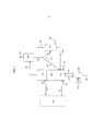
Фиг.1 иллюстрирует общий принцип изобретения, включая зону восстановления в предпочтительном варианте выполнения (с осаждением агломерированных зол).Figure 1 illustrates the general principle of the invention, including a reduction zone in a preferred embodiment (with deposition of agglomerated sols).
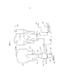
Фиг. 2 иллюстрирует частный вариант выполнения реакционных зон R1, R2 и зоны разделения S3.FIG. 2 illustrates a particular embodiment of reaction zones R1, R2 and separation zone S3.
Фиг. 3 - пример распределения гранулометрического состава летучих зол, в котором показано совокупное количество в массовых процентах в зависимости от диаметра частиц (dp в микронах).FIG. 3 is an example of the distribution of particle size distribution of volatile ashes, which shows the total amount in mass percent depending on the particle diameter (dp in microns).
Фигура 1:Figure 1:
зона восстановления (топливный реактор) в основном включает в себя 3 зоны:recovery zone (fuel reactor) mainly includes 3 zones:
- первую зону R1 установления контакта частиц твердой загрузки с частицами металлических оксидов, работающую в плотном кипящем слое,- the first zone R1 establishing contact of the particles of the solid charge with particles of metal oxides, working in a dense fluidized bed,
- зону сжигания (или вторую реакционную зону) R2 газообразных отходов, выходящих из первой реакционной зоны, в присутствии частиц металлических оксидов и твердого топлива, выходящих из зоны R1, предпочтительно работающую в разбавленном кипящем слое,- a combustion zone (or second reaction zone) R2 of gaseous waste leaving the first reaction zone in the presence of particles of metal oxides and solid fuel leaving zone R1, preferably operating in a dilute fluidized bed,
- зону быстрого разделения (S3) внутри смеси, выходящей из зоны сжигания R2, обеспечивающую разделение газа, частиц несгоревшего твердого топлива и частиц металлических оксидов.- a quick separation zone (S3) inside the mixture leaving the combustion zone R2, which ensures the separation of gas, unburned solid fuel particles and metal oxide particles.
Установка дополнительно содержит зону S4 очистки дымов от пыли, зону S5 разделения посредством декантации, зону S6 осаждения агломерированных зол и зону D7 разделения потока.The installation further comprises a dust clearing zone S4, a decantation separation zone S5, an agglomerated ash deposition zone S6, and a flow separation zone D7.
Для упрощения зона окисления в химическом контуре схематично показана на фиг. 1 в виде зоны (R0), ограниченной пунктирной линией.To simplify, the oxidation zone in the chemical circuit is schematically shown in FIG. 1 in the form of a zone (R0) bounded by a dashed line.
Материал-носитель кислорода, возвращающийся из зоны окисления R0 (в данном случае не показан), предпочтительно поступает в зону установления контакта в плотном кипящем слое R1 восстановительного реактора через трубопровод (8). Наиболее тяжелые частицы, выходящие из зоны быстрого разделения (S3) через трубопровод (9), поступают в зону окисления (R0) (топливный реактор). Твердое топливо подают в зону установления контакта R1 через один или несколько трубопроводов подачи топлива (10). Псевдоожижение зоны установления контакта R1 осуществляют через вход (11) газа псевдоожижения, как правило, окисляющего газа, такого как водяной пар или СО2, вводимые раздельно или в смеси.The oxygen carrier material returning from the oxidation zone R0 (not shown in this case) preferably enters the contacting zone in the dense fluidized bed R1 of the reduction reactor through a conduit (8). The heaviest particles exiting the quick separation zone (S3) through the pipeline (9) enter the oxidation zone (R0) (fuel reactor). Solid fuel is supplied to the contact zone R1 through one or more fuel supply pipelines (10). The fluidization of the contacting zone R1 is carried out through the inlet (11) of a fluidization gas, usually an oxidizing gas, such as water vapor or CO 2 , introduced separately or in a mixture.
В этой первой псевдоожиженной зоне в плотной фазе R1 твердое топливо, нагреваемое в присутствии окисляющего газа, подвергается удалению летучих веществ и частичной газификации. В этой зоне начинается сжигание образующихся газов в химическом контуре. Время пребывания частиц в этой первой зоне обычно составляет от 0,25 до 20 минут, предпочтительно от 2 до 10 минут. Как правило, поверхностная скорость газа составляет от 0,3 до 3 м/с в условиях реакции на выходе первой реакционной зоны R1.In this first fluidized zone in the dense phase R1, solid fuel, heated in the presence of an oxidizing gas, undergoes removal of volatiles and partial gasification. In this zone, the combustion of the resulting gases in the chemical circuit begins. The residence time of particles in this first zone is usually from 0.25 to 20 minutes, preferably from 2 to 10 minutes. Typically, the surface gas velocity is from 0.3 to 3 m / s under the reaction conditions at the outlet of the first reaction zone R1.
В этой зоне концентрация металлических оксидов равна не менее 10% по объему, и температура обычно составляет от 800 до 1000°С, предпочтительно превышает 900°С.In this zone, the concentration of metal oxides is at least 10% by volume, and the temperature is usually from 800 to 1000 ° C, preferably exceeds 900 ° C.
Газы, образующиеся при удалении летучих компонентов, газификации и сжигании, переносят частицы во вторую реакционную зону R2, предпочтительно работающую в режиме подвижного разбавленного кипящего слоя, в которой в основном происходят реакции сжигания остаточных газов удаления летучих компонентов и газификации. В этой зоне среднее время пребывания газов обычно составляет от 1 до 20 секунд, при этом среднее время пребывания твердых веществ колеблется от 2 секунд до 1 минуты. Скорость газов в этой зоне предпочтительно колеблется 3 до 30 м/с, предпочтительно от 5 до 15 м/с, и поток твердых носителей кислорода колеблется от 25 до 500 кг/с/м2 и предпочтительно составляет от 60 до 300 кг/с/м2, что способствует хорошему контакту между газами и частицами металлических оксидов. В этих условиях стремятся добиться объемной концентрации частиц менее 10%, предпочтительно менее 5%.Gases from the removal of volatile components, gasification and combustion transfer the particles to the second reaction zone R2, preferably operating in a movable diluted fluidized bed mode, in which mainly the combustion of residual gases for the removal of volatile components and gasification takes place. In this zone, the average residence time of gases is usually from 1 to 20 seconds, while the average residence time of solids ranges from 2 seconds to 1 minute. The gas velocity in this zone preferably ranges from 3 to 30 m / s, preferably from 5 to 15 m / s, and the flow of solid oxygen carriers ranges from 25 to 500 kg / s / m 2 and preferably ranges from 60 to 300 kg / s / m 2 , which contributes to good contact between gases and particles of metal oxides. Under these conditions, a volumetric concentration of particles of less than 10%, preferably less than 5%, is sought.
Затем смесь газов и частиц, выходящую из второй реакционной зоны R2, направляют в зону разделения (S3), в которой происходит быстрое отделение наиболее тяжелых частиц (в основном частиц материала-носителя кислорода) от наиболее легких частиц. Наиболее тяжелые частицы выходят из зоны разделения (S3) через трубопровод удаления (9) и поступают в реакционную зону окисления R0 (воздушный реактор). Для лучшего отделения плотных частиц и легких частиц в зоне разделения S3 с камерой S3 можно соединить трубопровод (12) подачи внешнего дополнительного газа для псевдоожижения плотных частиц в нижней части камеры вокруг выходного трубопровода второй реакционной зоны R2.Then, the mixture of gases and particles leaving the second reaction zone R2 is sent to the separation zone (S3), in which the heaviest particles (mainly oxygen carrier material particles) are rapidly separated from the lightest particles. The heaviest particles exit the separation zone (S3) through the removal line (9) and enter the oxidation reaction zone R0 (air reactor). For better separation of dense particles and light particles in the separation zone S3, an additional additional gas supply pipe (12) can be connected to the chamber S3 to fluidize the dense particles in the lower part of the chamber around the outlet pipe of the second reaction zone R2.
Наиболее легкие частицы, в основном представляющие собой частицы несгоревшего топлива, летучие золы и наиболее легкие частицы материала-носителя кислорода, увлекаются газообразными продуктами сжигания, в основном содержащими СО2 и водяной пар, и выходят из топливного реактора через трубопровод удаления (13). Предпочтительно поверхностная скорость газов в разбавленной фазе зоны S3 в результате прохождения дымов сжигания и возможного добавления внешнего газа соответствует значению от 30 до 300% средней конечной скорости падения частиц носителя кислорода, и предпочтительно составляет от 50 до 150% средней конечной скорости падения частиц носителя кислорода.The lightest particles, which are mainly particles of unburned fuel, fly ash and the lightest particles of an oxygen carrier material, are entrained in gaseous products of combustion, mainly containing CO 2 and water vapor, and exit the fuel reactor through a removal pipeline (13). Preferably, the surface velocity of the gases in the diluted phase of zone S3 as a result of the passage of combustion fumes and the possible addition of external gas corresponds to a value of from 30 to 300% of the average final rate of incidence of oxygen carrier particles, and preferably ranges from 50 to 150% of the average final rate of incidence of oxygen carrier particles.
Трубопровод (9) позволяет удалять наиболее плотные частицы среды, то есть большинство частиц металлических оксидов, восстановленных при контакте с углем в зонах R1 и R2, в окислительный реактор (воздушный реактор, схематично показанный пунктирной линией в виде зоны (R0)), а также небольшие количества летучих зол и несгоревшего топлива, которые не были отделены в зоне S3.The pipeline (9) allows you to remove the most dense particles of the medium, that is, most particles of metal oxides reduced by contact with coal in zones R1 and R2, in an oxidation reactor (air reactor, schematically shown by a dashed line in the form of a zone (R0)), and small amounts of fly ash and unburned fuel that were not separated in zone S3.
Легкие частицы, выходящие из зоны восстановления вместе с газообразными продуктами сжигания через трубопровод удаления (13), направляются затем в зону пылеулавливания S4, состоящую из одной или двух ступеней разделения. Разделение происходит, например, в циклонах, которые являются хорошо известными специалисту технологическими элементами. Это пылеулавливание позволяет рекуперировать не менее 99% частиц, предпочтительно не менее 99,5% частиц, перемещаемых в дымах сжигания, на выходе топливного реактора. Очищенные от пыли газы выходят из зоны пылеулавливания S4 через трубопровод удаления (14) и поступают для возможной пост-обработки на выходе реакционной зоны в зонах, таких как: зона отбора тепла, позволяющая понизить температуру дымов до значения, близкого к их точке росы, с одновременным теплообменом с паром, зона отделения загрязнений (Sox, NOx и т.д.), зона последнего пылеулавливания, позволяющая снизить содержание частиц в дымах до концентрации, достаточной для обеспечения сжатия СО2, зона конденсации водяного пара и зона сжатия дымов, содержащих в основном СО2 после конденсации воды.Light particles leaving the reduction zone together with gaseous products of combustion through the removal line (13) are then sent to the dust collection zone S4, consisting of one or two separation stages. The separation occurs, for example, in cyclones, which are well-known specialist technological elements. This dust collection allows recovery of at least 99% of the particles, preferably at least 99.5% of the particles transported in the combustion fumes at the outlet of the fuel reactor. Dust-free gases leave the dust collection zone S4 through the removal pipeline (14) and enter for possible post-treatment at the outlet of the reaction zone in areas such as: a heat extraction zone, which allows lowering the temperature of the smoke to a value close to their dew point, s simultaneous heat exchange with steam, the zone of separation of contaminants (Sox, NOx, etc.), the zone of the last dust collection, which allows to reduce the content of particles in fumes to a concentration sufficient to ensure compression of CO 2 , the condensation zone of water vapor and the compression zone of fumes, contents living mainly with CO 2 after water condensation.
Отделенные от дымов частицы выходят из зоны сжигания через трубопровод удаления (15) и направляются, - по крайней мере, что касается частиц, выходящих из первой ступни разделения в случае использования нескольких ступеней, - в зону разделения D7 потока, представляющую собой, например, кипящий слой с трубопроводом (15) входа частиц и двумя трубопроводами (16) и (17) выхода частиц, предпочтительно расположенными в плотной фазе кипящего слоя, или любое другое известное специалисту средство, например, такое как двойной сильфон. Эти два потока (16) и (17) имеют сходный состав частиц.Particles separated from fumes leave the combustion zone through a removal line (15) and are sent, at least with regard to particles leaving the first separation stage in the case of several stages, to the flow separation zone D7, which is, for example, boiling a layer with a particle inlet conduit (15) and two particle outlet conduits (16) and (17), preferably located in the dense phase of the fluidized bed, or any other means known to those skilled in the art, for example, such as a double bellows. These two streams (16) and (17) have a similar particle composition.
Поток частиц (16) предпочтительно представляет собой большую часть, то есть не менее 50%, предпочтительно не менее 80% потока частиц, перемещаемого в трубопроводе (13), и рециркулируется непосредственно в первую реакционную зону R1.The particle stream (16) is preferably a large part, i.e. at least 50%, preferably at least 80% of the particle stream transported in the conduit (13) and is recycled directly to the first reaction zone R1.
Поток частиц (17), предпочтительно представляющий собой меньшую часть первоначального потока, направляется в зону S5 разделения посредством декантации, содержащую, например, кипящий слой, из которого легкие частицы выходят через трубопровод удаления (18), увлекаемые газом псевдоожижения, который поступает через трубопровод подачи (20). В кипящем слое, образующем зону S5 разделения посредством декантации, скорость регулируют таким образом, чтобы обеспечивать удаление летучих зол с расходом, соответствующим расходу зол в потоке, создаваемом при сжигании. Диаметр камеры S5, позволяющий удалять золы, регулируют в зависимости от предусматриваемого количества зол. Действительно, перемещение частиц из кипящего слоя зависит от концентрации частиц, которые могут увлекаться в кипящем слое, и от сечения пустого ствола декантатора. Скорость газа тоже регулируют в зависимости от потребностей разделения. Скорость газа влияет также на количество увлекаемого материала, но при этом ухудшает характеристики увлекаемых материалов. Чем выше скорость, тем более тяжелые частицы могут увлекаться. Как правило, скорость газа составляет от 0,3 до 1,5 м/с, предпочтительно находится в диапазоне 0,4-1 м/с, чтобы получать потоки увлекаемых частиц от 0,01 до 5 кг/с/м2, предпочтительно от 0,05 до 0,5 кг/с/м2. Чем выше скорость, тем ниже концентрация зол в остаточном потоке (20), рециркулируемом в топливный реактор.The particle stream (17), preferably representing a smaller part of the initial stream, is sent to the separation zone S5 by decantation, containing, for example, a fluidized bed from which light particles exit through the removal line (18), entrained by the fluidization gas that enters through the supply line (twenty). In the fluidized bed forming the separation zone S5 by decantation, the speed is controlled in such a way as to ensure the removal of volatile ash with a flow rate corresponding to the flow rate of ash in the stream created during combustion. The diameter of the chamber S5, allowing to remove the ash, is regulated depending on the intended amount of ash. Indeed, the movement of particles from the fluidized bed depends on the concentration of particles that may be entrained in the fluidized bed and on the cross section of the empty decanter barrel. The gas speed is also regulated depending on the needs of the separation. The gas velocity also affects the amount of entrained material, but at the same time degrades the characteristics of entrained materials. The higher the speed, the heavier particles can get involved. Typically, the gas velocity is from 0.3 to 1.5 m / s, preferably in the range of 0.4-1 m / s, in order to obtain entrained particle flows from 0.01 to 5 kg / s / m 2 , preferably from 0.05 to 0.5 kg / s / m 2 . The higher the speed, the lower the concentration of ash in the residual stream (20) recycled to the fuel reactor.
Псевдоожижение зоны S5 разделения посредством декантации осуществляют при помощи газа, тщательно выбираемого в зависимости от потребностей способа. декантацию можно осуществлять при помощи газа-носителя, состоящего из воздуха. В этих условиях газ псевдоожижения, по меньшей мере, частично повторно окисляет частицы материала-носителя кислорода и частицы несгоревшего твердого топлива. В этих условиях можно использовать средства, позволяющие удалять тепло в этой зоне для охлаждения кипящего слоя и/или его газообразных отходов. В этих условиях дымы, выходящие из зоны разделения посредством декантации, не смешиваются с дымами восстановительного реактора, выходящими через трубопровод удаления (14), а могут, например, смешиваться с газообразными отходами воздушного реактора или могут подвергаться отдельной обработке.The fluidization of the separation zone S5 by decantation is carried out using a gas carefully selected depending on the needs of the method. decantation can be carried out using a carrier gas consisting of air. Under these conditions, the fluidized gas at least partially reoxidizes the particles of the oxygen carrier material and the particles of unburned solid fuel. Under these conditions, you can use tools that allow you to remove heat in this zone to cool the fluidized bed and / or its gaseous waste. Under these conditions, the fumes leaving the separation zone by decantation are not mixed with the fumes of the reduction reactor leaving the removal line (14), but can, for example, be mixed with gaseous waste from the air reactor or can be separately treated.
Можно также использовать газ, такой как СО2, для осуществления разделения посредством декантации в кипящем слое. В этих условиях отходы декантатора, выходящие через трубопровод (18), могут смешиваться с домами топливного реактора, выходящими через трубопровод удаления (14) после пост-обработки, обеспечивающей удаление частиц угля, например, в зоне дожигания несгоревших частиц угля.You can also use a gas, such as CO 2 to carry out the separation by decantation in a fluidized bed. Under these conditions, the decanter waste exiting through the pipeline (18) can be mixed with the houses of the fuel reactor exiting through the removal pipeline (14) after post-treatment, which ensures the removal of coal particles, for example, in the afterburning area of unburned coal particles.
Для осуществления разделения посредством декантации можно также предусмотреть другие газы, такие как водяной пар.Other gases, such as water vapor, may also be provided to effect separation by decantation.
Предпочтительно прохождение частиц между делителем потока D7 и первой реакционной зоной R1, между делителем D7 и разделителем-декантатором S5 и между разделителем-декантатором S5 и зоной R1 восстановительного реактора контролируют при помощи механических вентилей, таких как L-образные вентили.Preferably, the passage of particles between the flow divider D7 and the first reaction zone R1, between the divider D7 and the separator-decanter S5 and between the separator-decanter S5 and the zone R1 of the reduction reactor is controlled by mechanical valves, such as L-shaped valves.
Зона S5 разделения посредством декантации позволяет удалять мелкие частицы зол. Разделение посредством декантации позволяет также удалять мелкие частицы металлического оксида, получаемые в ходе способа при истирании. Выбор высокой скорости декантации позволяет удалять частицы металлического оксида-носителя кислорода, разрушающиеся при циркуляции частиц между воздушным реактором (зона окисления) и топливным реактором (зона восстановления).Separation zone S5 by decantation allows the removal of fine ash particles. Separation by decantation also allows the removal of small particles of metal oxide obtained during the process of abrasion. The choice of a high decantation rate makes it possible to remove particles of the metal oxide carrier oxygen, which are destroyed during the circulation of particles between the air reactor (oxidation zone) and the fuel reactor (reduction zone).
В предпочтительном варианте выполнения псевдоожиженная зона S6, обеспечивающая осаждение топочных зол, которые имеют очень большой размер по сравнению с частицами материала-носителя кислорода и твердого топлива, расположена под зоной установления контакта R1, для обеспечения удаления топочных зол. В эту зону через трубопровод (21) поступает смесь частиц, в основном содержащая агломерированные золы и металлический оксид, а также незначительные количества летучих зол и топлива. Псевдоожижение зоны S6 разделения происходит при низкой скорости псевдоожижения, соответствующей 1-10-кратной минимальной скорости псевдоожижения частиц материала-носителя кислорода при помощи частично окисляющего газа, такого как Н2О или СО2, раздельно или в смеси, поступающего через один или несколько трубопроводов подачи (22). Более плотные агломерированные частицы будут стремиться к осаждению на дне зоны S6, тогда как более легкие частицы (не агломерированный носитель кислорода, летучие золы и несгоревший уголь) хорошо поддаются псевдоожижению и могут быть рециркулированы в зону R1 через трубопровод (23).In a preferred embodiment, the fluidized zone S6, which provides for the deposition of furnace ash, which is very large in comparison with the particles of the carrier material of oxygen and solid fuel, is located below the contact zone R1, to ensure removal of furnace ash. A mixture of particles, mainly containing agglomerated ash and metal oxide, as well as insignificant amounts of volatile ash and fuel, enters this zone through pipeline (21). The fluidization of the separation zone S6 occurs at a low fluidization rate corresponding to a 1-10-fold minimum fluidization rate of the particles of the oxygen carrier material using a partially oxidizing gas, such as H 2 O or CO 2 , separately or in a mixture supplied through one or more pipelines feed (22). The denser agglomerated particles will tend to precipitate at the bottom of zone S6, while lighter particles (non-agglomerated oxygen carrier, fly ash and unburned coal) can be well fluidized and can be recycled to zone R1 via pipeline (23).
В основании зоны S6 средства извлечения, такие как охлаждаемый шнек, позволяют извлекать поток частиц (24), содержащий не менее 10% масс.% топочных зол.At the base of zone S6, extraction means, such as a cooled screw, allow the particle stream (24) to be recovered containing at least 10% by weight of furnace ash.
Фигура 2:Figure 2:
Фиг. 2 иллюстрирует частный вариант применения зоны восстановления в рамках заявленного способа. Для упрощения на фиг. 2 зона окисления химического контура не показана.FIG. 2 illustrates a particular application of the recovery zone in the framework of the claimed method. For simplicity, FIG. 2 oxidation zone of the chemical circuit is not shown.
Как показано на фиг. 2, зона восстановления, состоящая из трех зон (R1, R2, S3), содержит плотный кипящий слой R1, над которым находится конус ускорения, сообщающийся с транспортной трубой R2, обеспечивающей прохождение потока в разбавленном кипящем слое, при этом транспортная труба R2 выходит в зону разделения S3, представляющую собой камеру большого диаметра, в которой скорость газа регулируют для обеспечения отделения частиц носителя кислорода, в основном удаляемых в (9), от более легких частиц (несгоревшее топливо, летучие золы и мелкие частицы материала-носителя кислорода), удаляемых в (13) в дымоход. Средства пылеулавливания в дымоходе (13) состоят из двух ступеней последовательных циклонов S4. Частицы, отделяемые этими циклонами S4, выбрасываются в кипящий слой D7, работающий при скорости псевдоожижения, близкой к минимальной скорости псевдоожижения, чтобы избегать любого увлечения частиц с газом псевдоожижения, и позволяющий разделить на две части поток отделенных частиц при помощи двух трубопроводов (16) и (17), соединенных с плотной фазой кипящего слоя D7. Поток (16) рециркулируют в восстановительный реактор, а поток (17) направляют в кипящий слой S5. В кипящем слое S5 скорость, сообщаемая газу псевдоожижения, является высокой и способствует увлечению легких частиц (летучие золы и, возможно, несгоревшее топливо, а также мелкие частицы материала-носителя кислорода), которые выходят вместе с газом псевдоожижения в трубопровод (18). Остальную часть частиц рециркулируют в первую зону установления контакта восстановительного реактора R1.As shown in FIG. 2, the recovery zone, consisting of three zones (R1, R2, S3), contains a dense fluidized bed R1, over which there is an acceleration cone in communication with the transport pipe R2, which allows flow in the diluted fluidized bed, while the transport pipe R2 exits the separation zone S3, which is a large-diameter chamber, in which the gas velocity is controlled to separate oxygen carrier particles, which are mainly removed in (9), from lighter particles (unburned fuel, fly ash and small particles of the carrier material loroda) being removed (13) to the chimney. The dust collection means in the chimney (13) consist of two stages of successive cyclones S4. Particles separated by these cyclones S4 are ejected into a fluidized bed D7 operating at a fluidization rate close to the minimum fluidization rate, to avoid any entrainment of particles with the fluidization gas, and allowing the flow of separated particles to be divided into two parts using two pipelines (16) and (17) connected to the dense phase of the fluidized bed D7. Stream (16) is recycled to the reduction reactor, and stream (17) is sent to the fluidized bed S5. In the fluidized bed S5, the velocity imparted by the fluidization gas is high and contributes to the entrainment of light particles (fly ash and possibly unburned fuel, as well as small particles of oxygen carrier material) that exit together with the fluidization gas into the pipeline (18). The rest of the particles are recycled to the first contacting zone of the reduction reactor R1.
В нижнем продолжении зоны R1 сжигания в плотной фазе усеченная конусная секция S6 обеспечивает осаждение агломерированных зол, которые постепенно опускаются в нижнюю часть усеченного конусного сечения S6. Предпочтительно скорость псевдоожижения вдоль усеченной конусной секции S6 составляет от 1 до 3-кратной минимальной скорости псевдоожижения частиц материала-носителя кислорода, чтобы способствовать осаждению агломерированных зол, которые являются намного более крупными, чем материал-носитель кислорода. В этих условиях не агломерированные частицы оксидов, летучие золы и топливо могут проходить в двух направлениях между зоной S6 и зоной R1. Половина угла конуса относительно вертикали предпочтительно составляет от 5 до 30°, предпочтительно имеет значение около 15°. В основании конуса охлаждаемый шнек обеспечивает удаление агломерированных зол в смеси с частью частиц материала-носителя кислорода. В усеченной конусной секции, начиная от низа конуса, ступенчато расположены аэрационные каналы. В основании конуса на первом уровне нагнетаемый аэрационный поток соответствует, например, расходу, создающему от 1 до 3-кратной минимальной скорости материала-носителя кислорода на втором уровне, находящемся в конусе выше. На втором уровне расход нагнетаемого потока соответствует необходимому дополнению аэрации, создающему скорость, равную 1-3-кратной минимальной скорости псевдоожижения материала-носителя кислорода на третьем уровне, находящемся в конусе выше, и так далее до самого основания топливного реактора. В зависимости от высоты конуса число аэрационных каналов определяют таким образом, чтобы нагнетание производилось примерно через каждый метр. Предпочтительно нагнетаемым аэрационным газом является СО2 или водяной пар.In the lower extension of the dense phase combustion zone R1, the truncated conical section S6 provides for the deposition of agglomerated ashes, which gradually descend into the lower part of the truncated conical section S6. Preferably, the fluidization rate along the truncated conical section S6 is from 1 to 3 times the minimum fluidization speed of the particles of the oxygen carrier material to facilitate the deposition of agglomerated sols that are much larger than the oxygen carrier material. Under these conditions, non-agglomerated oxide particles, fly ash and fuel can pass in two directions between zone S6 and zone R1. The half angle of the cone relative to the vertical is preferably from 5 to 30 °, preferably has a value of about 15 °. At the base of the cone, the cooled screw removes agglomerated ashes mixed with part of the particles of the oxygen carrier material. In the truncated conical section, starting from the bottom of the cone, aeration channels are stepwise located. At the base of the cone at the first level, the injected aeration flow corresponds, for example, to a flow rate that creates from 1 to 3 times the minimum speed of the oxygen carrier material at the second level, located in the cone above. At the second level, the flow rate of the injected flow corresponds to the necessary aeration supplement, creating a speed equal to 1-3 times the minimum fluidization rate of the oxygen carrier material at the third level, located in the cone above, and so on to the very base of the fuel reactor. Depending on the height of the cone, the number of aeration channels is determined in such a way that the injection is carried out approximately every meter. Preferably, the injected aeration gas is CO 2 or water vapor.
Работе описанного выше способа способствует применение материала-носителя кислорода, имеющего гранулометрический состав и плотность зерна, способствующие разделению с частицами летучих зол, несгоревшего топлива и агломерированных зол. Предпочтительно гранулометрический состав носителя кислорода выбирают таким образом, чтобы 90 масс.% частиц имели гранулометрический размер от 100 до 500 микрон, предпочтительно 90% от 150 до 300 микрон, еще предпочтительнее 95% от 150 до 300 микрон.The operation of the method described above is facilitated by the use of an oxygen carrier material having a particle size distribution and grain density that facilitate separation of volatile ashes, unburned fuel and agglomerated ashes with particles. Preferably, the particle size distribution of the oxygen carrier is selected so that 90 wt.% Of the particles have a particle size of 100 to 500 microns, preferably 90% of 150 to 300 microns, even more preferably 95% of 150 to 300 microns.
Кроме того, плотность зерна частиц носителя кислорода предпочтительно превышает 2500 кг/м3, предпочтительно превышает 3400кг/м3 и еще предпочтительнее - превышает 4000 кг/м3.Furthermore, the oxygen density of the carrier particles, preferably grain than 2500 kg / m 3, preferably greater than 3400kg / m 3 and more preferably - higher than 4000 kg / m 3.
Фигура 3: Фиг. 3 иллюстрирует гранулометрический состав летучих зол, производимых при сжигании угля в химическом контуре согласно представленному ниже примеру.Figure 3: FIG. 3 illustrates the particle size distribution of fly ash produced by burning coal in a chemical circuit according to the example below.
ПримерExample
Следующий пример позволяет проиллюстрировать изобретение на основании моделирования работы установки мощностью 3 МВт.ч.The following example allows to illustrate the invention on the basis of modeling the operation of a plant with a capacity of 3 MWh.
В эту установку загружают уголь с расходом 420 кг/ч при содержании зол 13,9 масс.% и при содержании летучих веществ 29,9%.Coal is loaded into this unit with a flow rate of 420 kg / h with an ash content of 13.9 mass% and with a volatile content of 29.9%.
Уголь загружают в топливный реактор с гранулометрическим составом, при котором менее 2% угля имеет размер частиц, превышающий 200 микрон.Coal is loaded into a fuel reactor with a particle size distribution in which less than 2% of the coal has a particle size exceeding 200 microns.
Гранулометрический состав носителя кислорода является таким, что 90 масс.% частиц имеют гранулометрический размер от 150 до 300 микрон, а плотность носителя кислорода близка к 4000 кг/м3.The granulometric composition of the oxygen carrier is such that 90 wt.% Of the particles have a particle size distribution of 150 to 300 microns, and the density of the oxygen carrier is close to 4000 kg / m 3 .
В качестве примера гранулометрический состав летучих зол представлен на фиг. 3.By way of example, the particle size distribution of fly ash is shown in FIG. 3.
Топливный реактор содержит три зоны:The fuel reactor contains three zones:
- первую реакционную зону R1 установления контакта частиц твердой загрузки с частицами металлических оксидов в плотном кипящем слое,- the first reaction zone R1 establishing contact of the particles of the solid charge with particles of metal oxides in a dense fluidized bed,
- зону сжигания в разбавленной фазе (вторая реакционная зона R2) газообразных отходов, выходящих из первой реакционной зоны, в присутствии частиц металлических оксидов,- a combustion zone in a dilute phase (second reaction zone R2) of gaseous waste leaving the first reaction zone in the presence of particles of metal oxides,
- зону S3 разделения частиц внутри смеси, выходящей из зоны сжигания в разбавленной фазе, позволяющую отбирать вместе с дымами большую часть частиц недожога.- the zone S3 of separation of particles inside the mixture, leaving the combustion zone in the diluted phase, allowing you to select most of the particles of the burn together with the fumes.
Сжигание происходит в топливном реакторе при контакте с металлическим оксидом, переносящим 1,9 масс.% кислорода, с расходом потока из воздушного реактора, составляющим около 35500 кг/ч.Burning occurs in a fuel reactor in contact with a metal oxide carrying 1.9 mass% oxygen, with a flow rate from the air reactor of about 35500 kg / h.
Поток (13), увлекаемый на выходе зоны S3 быстрого разделения, состоит из мелких частиц металлического оксида, летучих зол и частиц несгоревшего угля.The stream (13), carried away at the exit of the quick separation zone S3, consists of small particles of metallic oxide, volatile ashes and particles of unburned coal.
Этот поток имеет следующий состав:This stream has the following composition:
металлический оксид: 6000 кг/ч;metal oxide: 6000 kg / h;
золы: 340 кг/ч;ash: 340 kg / h;
несгоревший уголь = 100,5 кг/ч.unburnt coal = 100.5 kg / h.
После пылеулавливания отделенные частицы, выходящие через трубопровод (15) и увлекаемые в кипящий слой деления D7, имеют следующий состав:After dust collection, the separated particles leaving the pipeline (15) and entrained in the fluidized bed of division D7 have the following composition:
металлический оксид: 5990 кг/ч;metal oxide: 5990 kg / h;
золы: 333 кг/ч;ash: 333 kg / h;
несгоревший уголь = 100 кг/ч.unburnt coal = 100 kg / h.
Кипящий слой D7 делит поток (15) на два потока (16) и (17) одинакового состава, содержащих соответственно 85% и 15% потока (15). Кипящий слой D7 представляет собой кипящий слой диаметром 60 см, работающий при скорости псевдоожижения 8 см/с. Поток (22), питающий кипящий слой-декантатор, имеет следующий состав:The fluidized bed D7 divides the stream (15) into two streams (16) and (17) of the same composition, containing respectively 85% and 15% of the stream (15). The fluidized bed D7 is a fluidized bed with a diameter of 60 cm, operating at a fluidization rate of 8 cm / s. The stream (22) feeding the decanter fluidized bed has the following composition:
металлический оксид: 899 кг/ч;metal oxide: 899 kg / h;
золы: 50 кг/ч;ash: 50 kg / h;
несгоревший уголь = 15 кг/ч.unburnt coal = 15 kg / h.
Поток (16), возвращаемый в топливный реактор, имеет следующий состав:The stream (16) returned to the fuel reactor has the following composition:
металлический оксид: 5091 кг/ч;metal oxide: 5091 kg / h;
золы: 283 кг/ч;ash: 283 kg / h;
несгоревший уголь = 85 кг/ч.unburnt coal = 85 kg / h.
Декантатор позволяет удалить около 80% зол из потока (17). В данном случае декантатор представляет собой кипящий слой диаметром 0,8 м, работающий при скорости псевдоожижения 0,75 м/с. Псевдоожижение декантатора происходит при помощи СО2, поступающего через трубопровод (19). Поток, поступающий в декантатор через трубопровод (18), имеет следующий состав:The decanter allows you to remove about 80% of the evils from the stream (17). In this case, the decanter is a fluidized bed with a diameter of 0.8 m, operating at a fluidization speed of 0.75 m / s. Fluidization of the decanter occurs using CO 2 entering through the pipeline (19). The stream entering the decanter through the pipeline (18) has the following composition:
металлический оксид: 29 кг/ч;metal oxide: 29 kg / h;
золы: 40 кг/ч;ash: 40 kg / h;
несгоревший уголь = 12 кг/ч.unburnt coal = 12 kg / h.
Поток, выходящий через трубопровод (20) и обеспечивающий рециркуляцию в топливный реактор частиц, не увлекаемых в декантатор, имеет следующий состав:The stream exiting through the pipeline (20) and providing recirculation into the fuel reactor of particles not entrained in the decanter has the following composition:
металлический оксид: 870 кг/ч;metal oxide: 870 kg / h;
золы: 10 кг/ч;ash: 10 kg / h;
несгоревший уголь = 3 кг/ч.unburnt coal = 3 kg / h.
Низ зоны установления контакта R1 топливного реактора имеет диаметр 917 мм и продолжен в своей нижней части (снизу) конусом с половиной угла 15° относительно вертикали, имеющим высоту 1711 мм, в котором расположены 2 аэрационных уровня, один из которых находится в основании конуса и позволяет вводить 7 кг/ч пара, а другой находится на половине высоты и позволяет вводить 20 кг/ч пара. В этих условиях средняя скорость псевдоожижения металлического оксида имеет значение, близкое к 2-3-кратной минимальной скорости псевдоожижения металлических оксидов и позволяет извлекать около 9 кг/ч агломерированных зол средним диаметром от 0,5 до 5 мм в основании конуса при помощи средств извлечения (24), содержащих охлаждаемый шнек, в смеси с 30 кг/ч металлического оксида.The bottom of the contact zone R1 of the fuel reactor has a diameter of 917 mm and is continued in its lower part (bottom) with a cone with a half angle of 15 ° relative to the vertical, having a height of 1711 mm, in which there are 2 aeration levels, one of which is located at the base of the cone and allows enter 7 kg / h of steam, and the other is halfway up and allows you to enter 20 kg / h of steam. Under these conditions, the average fluidization rate of the metal oxide has a value close to 2-3 times the minimum fluidization rate of the metal oxides and allows the recovery of about 9 kg / h of agglomerated sols with an average diameter of 0.5 to 5 mm at the base of the cone using extraction means ( 24) containing a cooled screw mixed with 30 kg / h of metal oxide.
Поток (9), удаляющий частицы, не отделенные в S3, в воздушный реактор (R0), имеет следующий состав:The stream (9), which removes particles not separated in S3, into the air reactor (R0), has the following composition:
металлический оксид: 35441 кг/ч;metal oxide: 35441 kg / h;
золы: 2 кг/ч;ash: 2 kg / h;
несгоревший уголь = 8 кг/ч.unburnt coal = 8 kg / h.
Золы и уголь, направляемые в воздушный реактор, удаляются в ходе повторного окисления металлического оксида. Уголь, сгоревший в воздушном реакторе при контакте с воздухом, и золы удаляются с прохождением через циклон. Металлический оксид, предназначенный для компенсации потерь оксида во время декантации, добавляют в воздушный реактор периодически.Ashes and coal sent to the air reactor are removed during the re-oxidation of the metal oxide. Coal burned in an air reactor in contact with air and ash are removed through a cyclone. Metallic oxide, designed to compensate for oxide loss during decantation, is added to the air reactor periodically.
Представленный выше пример иллюстрирует работу способа сжигания угля в химическом контуре, позволяющего непрерывно удалять золы.The above example illustrates the operation of the method of burning coal in a chemical circuit, allowing continuous removal of ash.
Так, при сжигании угля образуется поток зол с расходом 58 кг/ч. Они удаляются в следующих потоках:So, when burning coal, a stream of ash is formed with a flow rate of 58 kg / h. They are deleted in the following threads:
- летучие золы, увлекаемые в воздушный реактор (зона окисления R0) потоком (9) после осаждения в смеси с материалом-носителем кислорода в зоне быстрого разделения S3 = 2 кг/ч;- fly ash, entrained in an air reactor (oxidation zone R0) by flow (9) after deposition in a mixture with oxygen carrier material in the fast separation zone S3 = 2 kg / h;
- агломерированные топочные золы, извлекаемые шнеком (24) = 9 кг/ч;- agglomerated furnace ash recovered by a screw (24) = 9 kg / h;
- летучие золы, увлекаемые на выходе циклонов S4 вместе с дымами топливного реактора в потоке (14) = 7 кг/ч;- fly ash, carried away at the outlet of S4 cyclones together with the fuel of the fuel reactor in a stream (14) = 7 kg / h;
- летучие золы, увлекаемые в газообразных отходах, выходящих через трубопровод (18) декантатора S5 = 40 кг/ч.- fly ash carried away in the gaseous waste leaving the decanter pipe (18) S5 = 40 kg / h.
Благодаря этому непрерывному удалению скапливание зол в установке остается ограниченным (циркуляция зол в топливном реакторе 350 кг/ч по сравнению с циркуляцией оксида 35500 кг/ч, то есть при концентрации около 1%).Due to this continuous removal, ash accumulation in the installation remains limited (ash circulation in the fuel reactor is 350 kg / h compared to oxide circulation 35500 kg / h, i.e. at a concentration of about 1%).
Кроме того, уголь сгорает в основном в топливном реакторе при контакте с металлическим оксидом, что позволяет предусматривать степень улавливания более 90%. Действительно, в топливный реактор поступает 420 кг/ч угля.In addition, coal burns mainly in a fuel reactor in contact with metal oxide, which allows for a capture rate of more than 90%. Indeed, 420 kg / h of coal enters the fuel reactor.
Несгоревший уголь перемещается в воздушный реактор (R0) через трубопровод (9) с расходом 8 кг/ч.Unburned coal is transported to the air reactor (R0) through the pipeline (9) with a flow rate of 8 kg / h.
Несгоревший уголь, увлекаемый в декантатор S5 через трубопровод (18), имеет расход 12 кг/ч.Unburned coal carried to the S5 decanter through a pipe (18) has a flow rate of 12 kg / h.
Несгоревший уголь, увлекаемый на выходе зоны S4 очистки дымов от пыли через трубопровод (14), имеет расход 0,5 кг/ч.Unburned coal carried away at the outlet of zone S4 of dust cleaning from the dust through the pipeline (14) has a flow rate of 0.5 kg / h.
Claims (16)
- приведение в контакт частиц твердой загрузки и частиц материала-носителя кислорода в первой реакционной зоне R1, работающей в плотном кипящем слое;
- сжигание газообразных отходов, выходящих из первой реакционной зоны R1, в присутствии частиц материала-носителя кислорода во второй реакционной зоне R2;
- разделение несгоревших частиц твердой загрузки, летучих зол и частиц материала-носителя кислорода внутри смеси, выходящей из зоны R2, в зоне быстрого разделения S3 для перемещения вместе с дымами горения (13) основной части несгоревших частиц твердой загрузки и летучих зол и направления основной части частиц материала-носителя кислорода в зону окисления R0;
- очистку от пыли дымов (13), выходящих из зоны быстрого разделения S3, в зоне очистки дымов от пыли S4 для удаления потока очищенных от пыли газов (14) и потока частиц (15), содержащего золы и плотные частицы, в основном образовавшиеся из частиц носителя кислорода и из частиц несгоревшей твердой загрузки;
- разделение потока частиц (15), отделенных на этапе пылеулавливания S4, на два потока в зоне разделения потока D7,
при этом один из них рециркулируют в реакционную зону R1, работающую в плотном кипящем слое, а другой направляют в зону разделения S5 посредством декантации;
- разделение посредством декантации в упомянутой зоне S5 для рекуперации зол и рециркуляции плотных частиц в первую реакционную зону R1.1. A method of burning a hydrocarbon charge from solid particles in a chemical circuit in which an oxygen carrier material in the form of particles is circulated, said method comprising at least:
- bringing into contact the particles of the solid charge and the particles of the oxygen carrier material in the first reaction zone R1 operating in a dense fluidized bed;
- burning gaseous wastes leaving the first reaction zone R1 in the presence of particles of oxygen carrier material in the second reaction zone R2;
- separation of unburned particles of solid charge, flying ash and particles of oxygen carrier material inside the mixture leaving zone R2, in the quick separation zone S3 to move together with combustion fumes (13) the main part of unburned particles of solid charge and flying ash and the direction of the main part particles of oxygen carrier material into the oxidation zone R0;
- dust removal of fumes (13) leaving the rapid separation zone S3 in the dust cleaning zone S4 to remove the dust-free gas stream (14) and the particle stream (15) containing ashes and dense particles, mainly formed from oxygen carrier particles and from unburned solid charge particles;
- separation of the stream of particles (15) separated in the dust collection step S4 into two streams in the separation zone of the stream D7,
while one of them is recycled to the reaction zone R1 operating in a dense fluidized bed, and the other is sent to the separation zone S5 by decantation;
- separation by decantation in the aforementioned zone S5 for the recovery of sols and recycling of dense particles in the first reaction zone R1.
- осаждение агломерированных топочных зол в нижней части первой реакционной зоны R1 в зоне псевдоожижения S6, расположенной под первой реакционной зоной R1,
- извлечение потока частиц (24), содержащего по меньшей мере 10 мас.% агломерированных топочных зол.2. The method according to p. 1, including:
- deposition of agglomerated furnace ash in the lower part of the first reaction zone R1 in the fluidization zone S6 located under the first reaction zone R1,
- recovering a particle stream (24) containing at least 10 wt.% agglomerated furnace ash.
- первую реакционную зону R1, содержащую вход для твердого топлива (10), вход для газа псевдоожижения (11) и вход для частиц носителя кислорода (8), поступающих из зоны окисления R0,
- вторую реакционную зону R2, в которую поступает газообразный отход сжигания, содержащий частицы, поступающие из первой реакционной зоны R1,
- зону быстрого разделения S3 твердых частиц, в которую поступает газообразный отход сжигания из второй реакционной зоны R2, содержащий золы, частицы носителя кислорода и частицы несгоревшей твердой загрузки, и которая содержит выходной трубопровод (9) для удаления большей части частиц материала-носителя кислорода в зону окисления R0,
- зону очистки дымов от пыли S4, в которую через вход (13) поступают наиболее легкие частицы, увлекаемые газообразными продуктами сжигания, выходящими из зоны быстрого разделения S3,
- зону разделения потока D7, в которую через вход (15) поступает поток частиц, отделенных от дымов в зоне очистки S4 дымов от пыли, при этом упомянутый поток содержит золы и плотные частицы, в основном образованные частицами носителя кислорода и частицами несгоревшей твердой загрузки,
- зону разделения S5 посредством декантации, в которую через вход (17) поступает меньшая часть потока частиц, разделенного в зоне разделения потока D7, и которая содержит трубопровод (19), обеспечивающий подачу газа псевдоожижения, и трубопровод (18) удаления легких частиц, в основном содержащих летучие золы и мелкие частицы материала-носителя кислорода,
- трубопровод (16), отходящий от зоны разделения потока D7, для непосредственной рециркуляции основной части потока частиц, разделенного в зоне разделения потока D7, в первую реакционную зону R1,
- трубопровод (20), отходящий от зоны разделения S5 посредством декантации, для рециркуляции плотных частиц, отделенных посредством декантации, в первую реакционную зону R1.13. Installation for burning solid hydrocarbon charge in the chemical oxidation-reduction circuit using the method according to one of claims. 1-12, wherein said apparatus comprises at least:
- the first reaction zone R1 containing an inlet for solid fuel (10), an inlet for a fluidized gas (11) and an input for oxygen carrier particles (8) coming from the oxidation zone R0,
- the second reaction zone R2, which receives the gaseous combustion waste containing particles coming from the first reaction zone R1,
- a zone of rapid separation S3 of solid particles, into which gaseous combustion waste from the second reaction zone R2, containing ash, particles of an oxygen carrier and particles of an unburned solid charge, enters, and which contains an outlet pipe (9) for removing most of the particles of an oxygen carrier material in oxidation zone R0,
- a dust cleaning zone S4 for smoke from which the lightest particles are entrained through the inlet (13), entrained by the gaseous products of combustion leaving the rapid separation zone S3,
- a separation zone of the stream D7, into which a stream of particles separated from the fumes from the dust removal zone S4 enters through the inlet (15), wherein said stream contains ashes and dense particles mainly formed by particles of an oxygen carrier and particles of an unburned solid charge,
- a separation zone S5 by decantation, into which a smaller part of the particle stream separated in the separation zone of the stream D7 enters through the inlet (17), and which contains a pipeline (19) supplying fluidization gas, and a pipe (18) for removing light particles, mainly containing fly ash and small particles of oxygen carrier material,
- a pipeline (16) extending from the separation zone of the stream D7 for direct recycling of the main part of the particle stream separated in the separation zone of the stream D7 to the first reaction zone R1,
- a pipeline (20) extending from the separation zone S5 by decantation to recycle the dense particles separated by decantation into the first reaction zone R1.
- трубопровод подачи агломерированных зол (21),
- зону псевдоожижения S6,
- один или несколько трубопроводов (22), обеспечивающих подачу газа псевдоожижения,
- выходной трубопровод (23) удаления частиц носителя кислорода для их рециркуляции в первую реакционную зону R1,
- средства извлечения потока частиц (24), содержащего по меньшей мере 10 мас.% агломерированных топочных зол.15. Installation according to one of paragraphs. 13 or 14, containing a deposition zone of agglomerated furnace ash, located under the first reaction zone R1 and containing:
- agglomerated ash supply pipeline (21),
- fluidization zone S6,
- one or more pipelines (22) providing fluidization gas supply,
- an outlet pipe (23) for removing oxygen carrier particles for recycling to the first reaction zone R1,
- means for extracting a particle stream (24) containing at least 10 wt.% agglomerated furnace ash.
Applications Claiming Priority (3)
| Application Number | Priority Date | Filing Date | Title |
|---|---|---|---|
| FR1102848A FR2980258B1 (en) | 2011-09-20 | 2011-09-20 | CHEMICAL LOOP COMBUSTION PROCESS WITH REMOVAL OF ASHES AND FINES IN THE REDUCTION AREA AND INSTALLATION USING SUCH A METHOD |
| FR1102848 | 2011-09-20 | ||
| PCT/FR2012/000336 WO2013041779A1 (en) | 2011-09-20 | 2012-08-09 | Chemical looping combustion method with removal of ash and fines in the reduction area, and a facility using such a method |
Publications (2)
| Publication Number | Publication Date |
|---|---|
| RU2014115717A RU2014115717A (en) | 2015-10-27 |
| RU2598503C2 true RU2598503C2 (en) | 2016-09-27 |
Family
ID=46832461
Family Applications (1)
| Application Number | Title | Priority Date | Filing Date |
|---|---|---|---|
| RU2014115717/06A RU2598503C2 (en) | 2011-09-20 | 2012-08-09 | Chemical looping combustion method with removal of ash and fines in reduction area, and facility using such method |
Country Status (14)
| Country | Link |
|---|---|
| US (1) | US9726369B2 (en) |
| EP (1) | EP2758711B1 (en) |
| JP (1) | JP2014526672A (en) |
| KR (1) | KR20140072109A (en) |
| CN (1) | CN103946633B (en) |
| AU (1) | AU2012311411B2 (en) |
| BR (1) | BR112014006453A2 (en) |
| CA (1) | CA2846993C (en) |
| ES (1) | ES2710890T3 (en) |
| FR (1) | FR2980258B1 (en) |
| PL (1) | PL2758711T3 (en) |
| RU (1) | RU2598503C2 (en) |
| WO (1) | WO2013041779A1 (en) |
| ZA (1) | ZA201401594B (en) |
Families Citing this family (19)
| Publication number | Priority date | Publication date | Assignee | Title |
|---|---|---|---|---|
| FR3004126B1 (en) * | 2013-04-05 | 2016-01-01 | IFP Energies Nouvelles | METHOD AND DEVICE FOR CHEMICAL BUCKLE COMBUSTION OF LIQUID HYDROCARBON LOADS |
| FR3007105B1 (en) * | 2013-06-13 | 2015-07-17 | IFP Energies Nouvelles | METHOD AND INSTALLATION OF COMBUSTION BY OXYDO-CHEMICAL LOOP REDUCTION OF A SOLID HYDROCARBON LOAD WITH REMOVAL OF HOME ASHES |
| FR3007104B1 (en) | 2013-06-13 | 2019-01-25 | IFP Energies Nouvelles | METHOD AND INSTALLATION OF COMBUSTION BY OXYDO-CHEMICAL LOOP REDUCTION OF A SOLID HYDROCARBONIC LOAD |
| JP6326982B2 (en) * | 2013-06-21 | 2018-05-23 | 東京瓦斯株式会社 | Chemical loop combustion method and oxygen carrier |
| CN103486576A (en) * | 2013-09-25 | 2014-01-01 | 上海锅炉厂有限公司 | Chemical chain combustion device and method for three-reactor structure |
| JP6214344B2 (en) * | 2013-10-31 | 2017-10-18 | 三菱日立パワーシステムズ株式会社 | Chemical looping combustion system and operating method thereof |
| JP6300646B2 (en) * | 2014-06-03 | 2018-03-28 | 三菱日立パワーシステムズ株式会社 | Chemical looping combustion system |
| FR3022611B1 (en) * | 2014-06-19 | 2016-07-08 | Ifp Energies Now | METHOD AND INSTALLATION OF COMBUSTION BY OXYDO-REDUCTION IN CHEMICAL LOOP WITH CHECKING HEAT EXCHANGES |
| US9765961B2 (en) * | 2015-03-17 | 2017-09-19 | Saudi Arabian Oil Company | Chemical looping combustion process with multiple fuel reaction zones and gravity feed of oxidized particles |
| CN104930518B (en) * | 2015-05-18 | 2017-09-29 | 华中科技大学 | A kind of low-carbon processing solid refuse and the method for suppressing bioxin generation |
| CN108204593B (en) * | 2018-01-30 | 2024-05-07 | 广州环保投资集团有限公司 | Method for incinerating garbage by chemical chains |
| FR3089828A1 (en) * | 2018-12-17 | 2020-06-19 | IFP Energies Nouvelles | CLC INSTALLATION COMPRISING A SOLID / SOLID SEPARATOR WITH INTEGRATED CYCLONIC ENCLOSURE |
| CN110125160A (en) * | 2019-04-25 | 2019-08-16 | 东南大学 | A kind of method of the burning chemistry chains processing plant of poor iron ore as oxygen carrier |
| FR3105795B1 (en) * | 2019-12-30 | 2022-08-05 | Total Raffinage Chimie | INTEGRATED PROCESS FOR THERMAL CONVERSION OF A HEAVY HYDROCARBON CHARGE AND INDIRECT COMBUSTION IN A CHEMICAL OXIDE-REDUCTION LOOP |
| WO2022006112A1 (en) * | 2020-06-29 | 2022-01-06 | Ohio State Innovation Foundation | Systems and methods for high reactant conversion through multiple reactant flow ratio staging |
| FR3118134B1 (en) * | 2020-12-18 | 2022-12-16 | Ifp Energies Now | Process and chemical looping combustion reactor comprising staged fluidization |
| CN114042425A (en) * | 2021-11-25 | 2022-02-15 | 浙江义九氢能源科技股份有限公司 | Special hydrogenation fluidized bed for borohydride |
| CN114574250B (en) * | 2022-04-14 | 2023-05-02 | 河南大学 | Method and device for preparing clean synthetic gas by biomass chemical chain gasification |
| FR3166687A1 (en) * | 2024-09-20 | 2026-03-27 | IFP Energies Nouvelles | CHEMICAL LOOP COMBUSTION PROCESS OF A FUEL COMPRISING A HIGH VOLATILE CONTENT |
Citations (6)
| Publication number | Priority date | Publication date | Assignee | Title |
|---|---|---|---|---|
| EP0211483A2 (en) * | 1985-06-13 | 1987-02-25 | Aalborg Ciserv International A/S | Fluidized-bed reactor and its operational process |
| SU1746129A1 (en) * | 1990-06-07 | 1992-07-07 | Уральский политехнический институт им.С.М.Кирова | Circulating fluidized-bed boiler |
| RU2006746C1 (en) * | 1990-06-21 | 1994-01-30 | Научно-производственное предприятие "ЭНЭКО" | Combustion process |
| RU2119120C1 (en) * | 1994-02-18 | 1998-09-20 | Дзе Бабкок энд Вилкокс Компани | Method and device for control of temperature of layer in circulating fluidized-bed reactor |
| RU43944U1 (en) * | 2004-11-16 | 2005-02-10 | Закрытое акционерное общество "Элиттехнострой" | THE SYSTEM FOR FEEDING A CUTTED ABNOSION TO THE BOILER OF A BOILER WITH A BOILER |
| EP2273192A1 (en) * | 2009-06-12 | 2011-01-12 | Alstom Technology Ltd | System for converting fuel material |
Family Cites Families (20)
| Publication number | Priority date | Publication date | Assignee | Title |
|---|---|---|---|---|
| US2394710A (en) * | 1943-08-30 | 1946-02-12 | Universal Oil Prod Co | Contacting fluids with solids |
| US3729551A (en) * | 1971-01-07 | 1973-04-24 | Cons Coal Co | Conversion of calcium sulfate to calcium oxide and elemental sulfur |
| FR2850156B1 (en) * | 2003-01-16 | 2005-12-30 | Alstom Switzerland Ltd | COMBUSTION INSTALLATION WITH CO2 RECOVERY |
| FR2883773B1 (en) * | 2005-04-01 | 2007-05-11 | Alstom Sa | COMBUSTION DEVICE PRODUCING HYDROGEN WITH REUSE OF CO2 CAPTURE |
| AU2005335060A1 (en) * | 2005-08-01 | 2007-02-08 | Alstom Technology Ltd | Modular fluidised bed reactor |
| US7540893B2 (en) * | 2005-12-06 | 2009-06-02 | General Electric Company | System and method for producing synthesis gas |
| DE112007000518A5 (en) * | 2006-03-16 | 2009-01-22 | Alstom Technology Ltd. | Plant for the production of electricity |
| US7824574B2 (en) * | 2006-09-21 | 2010-11-02 | Eltron Research & Development | Cyclic catalytic upgrading of chemical species using metal oxide materials |
| CN101113343A (en) * | 2007-06-29 | 2008-01-30 | 合肥天焱绿色能源开发有限公司 | Ash slag self-agglomeration biomass fluidized bed gasification furnace |
| FR2919813B1 (en) * | 2007-08-06 | 2010-08-27 | Air Liquide | METHOD OF DEOXYGENING SMOKE AND INSTALLATION FOR ITS IMPLEMENTATION |
| CN101261010B (en) * | 2008-04-22 | 2011-06-08 | 青岛科技大学 | Double distribution plate coal-base serial fluidized-bed chemical chain combustion apparatus |
| EP2123978A1 (en) * | 2008-05-23 | 2009-11-25 | Alstom Technology Ltd | Process for using a facility for combusting carbonaceous materials and relating facility |
| CN101349423B (en) * | 2008-09-05 | 2010-07-21 | 西安交通大学 | A Double Circulating Fluidized Bed System for Chemical Looping Combustion |
| FR2936301B1 (en) * | 2008-09-23 | 2010-09-10 | Inst Francais Du Petrole | OPTIMIZED CHEMICAL LOOP COMBUSTION METHOD AND DEVICE ON LIQUID HYDROCARBON LOADS |
| FR2941689B1 (en) * | 2009-01-30 | 2011-02-18 | Inst Francais Du Petrole | INTEGRATED OXIDATION, REDUCTION AND GASIFICATION PROCESS FOR THE PRODUCTION OF CHEMICAL LOOP SYNTHESIS GAS |
| CN101672530B (en) | 2009-08-12 | 2012-09-26 | 东南大学 | Method and device for burning chemistry chains based on iron or iron oxide |
| FR2960869B1 (en) * | 2010-06-02 | 2014-08-08 | Inst Francais Du Petrole | PROCESS AND PLANT FOR PRODUCING OXYGEN BY FLUIDIZED BED CHEMICAL LOOP |
| FR2960940B1 (en) * | 2010-06-02 | 2015-08-07 | Inst Francais Du Petrole | CHEMICAL LOOP COMBUSTION PROCESS WITH A REACTION ZONE INTEGRATING A GAS-SOLID SEPARATION AREA AND INSTALLATION USING SUCH A METHOD |
| CN201865710U (en) * | 2010-11-26 | 2011-06-15 | 绍兴文理学院 | Coal chemical-looping combustion power generating device |
| CN102183014B (en) * | 2011-03-10 | 2012-05-02 | 东南大学 | A coal pressurized high-density circulating fluidized bed chemical looping combustion method for separating CO2 |
-
2011
- 2011-09-20 FR FR1102848A patent/FR2980258B1/en not_active Expired - Fee Related
-
2012
- 2012-08-09 KR KR1020147010427A patent/KR20140072109A/en not_active Withdrawn
- 2012-08-09 CN CN201280045638.6A patent/CN103946633B/en not_active Expired - Fee Related
- 2012-08-09 PL PL12758535T patent/PL2758711T3/en unknown
- 2012-08-09 AU AU2012311411A patent/AU2012311411B2/en not_active Ceased
- 2012-08-09 EP EP12758535.4A patent/EP2758711B1/en not_active Not-in-force
- 2012-08-09 JP JP2014531285A patent/JP2014526672A/en active Pending
- 2012-08-09 BR BR112014006453A patent/BR112014006453A2/en active Search and Examination
- 2012-08-09 RU RU2014115717/06A patent/RU2598503C2/en not_active IP Right Cessation
- 2012-08-09 CA CA2846993A patent/CA2846993C/en not_active Expired - Fee Related
- 2012-08-09 WO PCT/FR2012/000336 patent/WO2013041779A1/en not_active Ceased
- 2012-08-09 US US14/346,133 patent/US9726369B2/en not_active Expired - Fee Related
- 2012-08-09 ES ES12758535T patent/ES2710890T3/en active Active
-
2014
- 2014-03-03 ZA ZA2014/01594A patent/ZA201401594B/en unknown
Patent Citations (6)
| Publication number | Priority date | Publication date | Assignee | Title |
|---|---|---|---|---|
| EP0211483A2 (en) * | 1985-06-13 | 1987-02-25 | Aalborg Ciserv International A/S | Fluidized-bed reactor and its operational process |
| SU1746129A1 (en) * | 1990-06-07 | 1992-07-07 | Уральский политехнический институт им.С.М.Кирова | Circulating fluidized-bed boiler |
| RU2006746C1 (en) * | 1990-06-21 | 1994-01-30 | Научно-производственное предприятие "ЭНЭКО" | Combustion process |
| RU2119120C1 (en) * | 1994-02-18 | 1998-09-20 | Дзе Бабкок энд Вилкокс Компани | Method and device for control of temperature of layer in circulating fluidized-bed reactor |
| RU43944U1 (en) * | 2004-11-16 | 2005-02-10 | Закрытое акционерное общество "Элиттехнострой" | THE SYSTEM FOR FEEDING A CUTTED ABNOSION TO THE BOILER OF A BOILER WITH A BOILER |
| EP2273192A1 (en) * | 2009-06-12 | 2011-01-12 | Alstom Technology Ltd | System for converting fuel material |
Also Published As
| Publication number | Publication date |
|---|---|
| CA2846993C (en) | 2019-09-17 |
| WO2013041779A1 (en) | 2013-03-28 |
| PL2758711T4 (en) | 2019-07-31 |
| JP2014526672A (en) | 2014-10-06 |
| ES2710890T3 (en) | 2019-04-29 |
| EP2758711A1 (en) | 2014-07-30 |
| FR2980258B1 (en) | 2017-12-29 |
| ZA201401594B (en) | 2014-12-23 |
| BR112014006453A2 (en) | 2017-04-25 |
| KR20140072109A (en) | 2014-06-12 |
| CN103946633A (en) | 2014-07-23 |
| FR2980258A1 (en) | 2013-03-22 |
| RU2014115717A (en) | 2015-10-27 |
| AU2012311411B2 (en) | 2017-05-25 |
| US9726369B2 (en) | 2017-08-08 |
| AU2012311411A1 (en) | 2014-03-27 |
| CA2846993A1 (en) | 2013-03-28 |
| US20140295359A1 (en) | 2014-10-02 |
| PL2758711T3 (en) | 2019-07-31 |
| EP2758711B1 (en) | 2018-10-24 |
| CN103946633B (en) | 2016-09-28 |
Similar Documents
| Publication | Publication Date | Title |
|---|---|---|
| RU2598503C2 (en) | Chemical looping combustion method with removal of ash and fines in reduction area, and facility using such method | |
| US9494315B2 (en) | Chemical-looping combustion method with ashes and fines removal at the oxidation zone outlet and plant using same | |
| CA2799133C (en) | Chemical looping combustion process with a reaction zone incorporating a gas/solid separation zone and plant using such a process | |
| US9714764B2 (en) | Chemical-looping combustion method with dilute phase removal of ashes and fines in the oxidationzone and plant using same | |
| US8499702B2 (en) | Char-handling processes in a pyrolysis system | |
| JP4138032B2 (en) | Carbonaceous material gasification method | |
| CN112469942A (en) | CLC installation comprising a solid/solid separator with a gas-solid mixture distribution device | |
| WO2020126703A1 (en) | Clc facility comprising a solid/solid separator incorporating a cyclonic enclosure |
Legal Events
| Date | Code | Title | Description |
|---|---|---|---|
| MM4A | The patent is invalid due to non-payment of fees |
Effective date: 20180810 |