RU2597133C2 - Filtering device for ultrasonic signal filtration - Google Patents
Filtering device for ultrasonic signal filtration Download PDFInfo
- Publication number
- RU2597133C2 RU2597133C2 RU2013127507/14A RU2013127507A RU2597133C2 RU 2597133 C2 RU2597133 C2 RU 2597133C2 RU 2013127507/14 A RU2013127507/14 A RU 2013127507/14A RU 2013127507 A RU2013127507 A RU 2013127507A RU 2597133 C2 RU2597133 C2 RU 2597133C2
- Authority
- RU
- Russia
- Prior art keywords
- module
- ultrasonic
- signal
- ultrasonic signal
- correction
- Prior art date
Links
Images

Classifications
-
- A—HUMAN NECESSITIES
- A61—MEDICAL OR VETERINARY SCIENCE; HYGIENE
- A61B—DIAGNOSIS; SURGERY; IDENTIFICATION
- A61B8/00—Diagnosis using ultrasonic, sonic or infrasonic waves
- A61B8/12—Diagnosis using ultrasonic, sonic or infrasonic waves in body cavities or body tracts, e.g. by using catheters
-
- A—HUMAN NECESSITIES
- A61—MEDICAL OR VETERINARY SCIENCE; HYGIENE
- A61B—DIAGNOSIS; SURGERY; IDENTIFICATION
- A61B8/00—Diagnosis using ultrasonic, sonic or infrasonic waves
- A61B8/08—Detecting organic movements or changes, e.g. tumours, cysts, swellings
- A61B8/0883—Detecting organic movements or changes, e.g. tumours, cysts, swellings for diagnosis of the heart
-
- A—HUMAN NECESSITIES
- A61—MEDICAL OR VETERINARY SCIENCE; HYGIENE
- A61B—DIAGNOSIS; SURGERY; IDENTIFICATION
- A61B8/00—Diagnosis using ultrasonic, sonic or infrasonic waves
- A61B8/52—Devices using data or image processing specially adapted for diagnosis using ultrasonic, sonic or infrasonic waves
- A61B8/5269—Devices using data or image processing specially adapted for diagnosis using ultrasonic, sonic or infrasonic waves involving detection or reduction of artifacts
-
- A—HUMAN NECESSITIES
- A61—MEDICAL OR VETERINARY SCIENCE; HYGIENE
- A61B—DIAGNOSIS; SURGERY; IDENTIFICATION
- A61B18/00—Surgical instruments, devices or methods for transferring non-mechanical forms of energy to or from the body
- A61B18/04—Surgical instruments, devices or methods for transferring non-mechanical forms of energy to or from the body by heating
- A61B18/12—Surgical instruments, devices or methods for transferring non-mechanical forms of energy to or from the body by heating by passing a current through the tissue to be heated, e.g. high-frequency current
- A61B18/14—Probes or electrodes therefor
- A61B18/1492—Probes or electrodes therefor having a flexible, catheter-like structure, e.g. for heart ablation
-
- A—HUMAN NECESSITIES
- A61—MEDICAL OR VETERINARY SCIENCE; HYGIENE
- A61B—DIAGNOSIS; SURGERY; IDENTIFICATION
- A61B17/00—Surgical instruments, devices or methods, e.g. tourniquets
- A61B2017/00017—Electrical control of surgical instruments
- A61B2017/00022—Sensing or detecting at the treatment site
- A61B2017/00106—Sensing or detecting at the treatment site ultrasonic
-
- A—HUMAN NECESSITIES
- A61—MEDICAL OR VETERINARY SCIENCE; HYGIENE
- A61B—DIAGNOSIS; SURGERY; IDENTIFICATION
- A61B90/00—Instruments, implements or accessories specially adapted for surgery or diagnosis and not covered by any of the groups A61B1/00 - A61B50/00, e.g. for luxation treatment or for protecting wound edges
- A61B90/06—Measuring instruments not otherwise provided for
- A61B2090/062—Measuring instruments not otherwise provided for penetration depth
Landscapes
- Health & Medical Sciences (AREA)
- Life Sciences & Earth Sciences (AREA)
- Engineering & Computer Science (AREA)
- Medical Informatics (AREA)
- Surgery (AREA)
- Pathology (AREA)
- Radiology & Medical Imaging (AREA)
- Biophysics (AREA)
- Biomedical Technology (AREA)
- Heart & Thoracic Surgery (AREA)
- Physics & Mathematics (AREA)
- Molecular Biology (AREA)
- Nuclear Medicine, Radiotherapy & Molecular Imaging (AREA)
- Animal Behavior & Ethology (AREA)
- General Health & Medical Sciences (AREA)
- Public Health (AREA)
- Veterinary Medicine (AREA)
- Computer Vision & Pattern Recognition (AREA)
- Cardiology (AREA)
- Ultra Sonic Daignosis Equipment (AREA)
- Investigating Or Analyzing Materials By The Use Of Ultrasonic Waves (AREA)
- Surgical Instruments (AREA)
Abstract
Description
ОБЛАСТЬ ТЕХНИКИ, К КОТОРОЙ ОТНОСИТСЯ ИЗОБРЕТЕНИЕFIELD OF THE INVENTION
Изобретение относится к фильтрующему устройству, способу фильтрации и компьютерной программе фильтрации для фильтрации ультразвукового сигнала. Изобретение также относится к ультразвуковому считывающему устройству, способу ультразвукового считывания и компьютерной программе ультразвукового считывания для считывания объекта.The invention relates to a filtering device, a filtering method and a computer filtering program for filtering an ultrasonic signal. The invention also relates to an ultrasonic reader, an ultrasonic reader method and an ultrasonic reader computer program for reading an object.
УРОВЕНЬ ТЕХНИКИBACKGROUND
В патенте США 5,409,000 описывается абляционный катетер с ультразвуковым преобразователем и абляционным электродом. Ультразвуковые волны вводятся в сердечную ткань, и ультразвуковые эхо-сигналы, которые возвращаются от сердечной ткани, принимаются ультразвуковым преобразователем и визуализируются на экране. Врач, выполняющий процедуру абляции, может наблюдать результирующее ультразвуковое изображение на экране, чтобы выполнять абляционную процедуру в зависимости от этого ультразвукового изображения. Абляционная процедура выполняется путем подачи радиочастотного (РЧ) тока на абляционный электрод, расположенный на наконечнике абляционного катетера.US Pat. No. 5,409,000 describes an ablation catheter with an ultrasound transducer and an ablation electrode. Ultrasonic waves are introduced into the heart tissue, and ultrasonic echo signals that are returned from the heart tissue are received by the ultrasound transducer and visualized on the screen. A doctor performing an ablation procedure can observe the resulting ultrasound image on a screen to perform an ablation procedure depending on this ultrasound image. The ablation procedure is performed by applying a radio frequency (RF) current to the ablation electrode located on the tip of the ablation catheter.
Недостатком РЧ абляции в сочетании с формированием ультразвукового изображения внутри одного и того же катетера является емкостная и/или кондуктивная связь РЧ сигнала с ультразвуковым сигналом, генерируемым ультразвуковым преобразователем и используемым для формирования ультразвукового изображения. Это снижает качество ультразвукового сигнала и тем самым ультразвукового изображения, используемого для отслеживания абляционной процедуры.A disadvantage of RF ablation in combination with the formation of an ultrasound image within the same catheter is the capacitive and / or conductive coupling of the RF signal with the ultrasound signal generated by the ultrasound transducer and used to form the ultrasound image. This reduces the quality of the ultrasound signal and thereby the ultrasound image used to track the ablation procedure.
СУЩНОСТЬ ИЗОБРЕТЕНИЯSUMMARY OF THE INVENTION
Задачей настоящего изобретения является обеспечение фильтрующего устройства, способа фильтрации и компьютерной программы фильтрации для фильтрации ультразвукового сигнала, в которых влияние электрического модуля, такого как РЧ абляционный электрод, может быть уменьшено. Дополнительной задачей настоящего изобретения является обеспечение ультразвукового считывающего устройства для считывания объекта, который содержит фильтрующее устройство, и соответствующего способа ультразвукового считывания и компьютерной программы ультразвукового считывания для считывания объекта.An object of the present invention is to provide a filtering device, a filtering method, and a computer filtering program for filtering an ultrasonic signal in which the effect of an electrical module, such as an RF ablation electrode, can be reduced. An additional objective of the present invention is the provision of an ultrasonic reader for reading an object that contains a filter device, and a corresponding method for ultrasonic reading and a computer program for ultrasonic reading for reading an object.
В первом аспекте настоящего изобретения представлено фильтрующее устройство для фильтрации ультразвукового сигнала, причем ультразвуковой сигнал подвергается влиянию электрического модуля и содержит первую часть, содержащую информацию об объекте, от которого был принят ультразвуковой сигнал, и вторую часть, не содержащую информацию об объекте, при этом фильтрующее устройство содержит:In a first aspect of the present invention, there is provided a filtering device for filtering an ultrasonic signal, the ultrasonic signal being influenced by an electric module and comprising a first part containing information about an object from which an ultrasonic signal was received and a second part not containing information about an object, while filtering The device contains:
- модуль определения корректирующего сигнала для определения корректирующего сигнала, указывающего влияние электрического модуля на ультразвуковой сигнал, из второй части ультразвукового сигнала;- a correction signal determination module for determining a correction signal indicating an effect of the electrical module on the ultrasonic signal from the second part of the ultrasonic signal;
- корректирующий модуль для коррекции первой части ультразвукового сигнала на основе определенного корректирующего сигнала, чтобы отфильтровать влияние электрического модуля из ультразвукового сигнала.- a correction module for correcting the first part of the ultrasonic signal based on the determined correction signal in order to filter out the influence of the electrical module from the ultrasonic signal.
Поскольку модуль определения корректирующего сигнала определяет корректирующий сигнал, указывающий влияние электрического модуля, которым является, например, РЧ абляционный электрод, на ультразвуковой сигнал, исходя из второй части, которая не содержит информацию об объекте, этот корректирующий сигнал обусловливается, например, нежелательными эффектами, такими как емкостная и/или кондуктивная связь электрического сигнала от электрического модуля с ультразвуковым сигналом. Первая часть ультразвукового сигнала содержит как информацию об объекте, так и информацию о нежелательных эффектах, таких как емкостная и/или кондуктивная связь. При коррекции первой части ультразвукового сигнала на основе определенного корректирующего сигнала, чтобы отфильтровать влияние электрического модуля из ультразвукового сигнала, желаемая информация об объекте становится более явной и легче извлекаемой из первой части ультразвукового сигнала. Поэтому, качество ультразвукового сигнала повышается.Since the correction signal determination module determines the correction signal indicating the effect of the electrical module, which is, for example, an RF ablation electrode, on the ultrasonic signal, based on the second part, which does not contain information about the object, this correction signal is caused, for example, by undesirable effects, such as a capacitive and / or conductive coupling of an electrical signal from an electrical module to an ultrasonic signal. The first part of the ultrasonic signal contains both information about the object and information about undesirable effects, such as capacitive and / or conductive coupling. When correcting the first part of the ultrasonic signal based on a specific correction signal in order to filter out the effect of the electrical module from the ultrasonic signal, the desired object information becomes more explicit and easier to extract from the first part of the ultrasonic signal. Therefore, the quality of the ultrasonic signal is improved.
Предпочтительно, электрическим модулем является электрод для подачи электрической энергии, в частности, РЧ энергии на объект, при этом влияние на ультразвуковой сигнал обусловливается емкостной и/или кондуктивной связью. В предпочтительном варианте осуществления электрическим модулем является РЧ абляционный электрод. Объектом преимущественно является сердце человека или животного, в частности, стенка сердца, и информация об объекте, которая содержится в ультразвуковом сигнале, преимущественно является информацией о сердечной ткани.Preferably, the electrical module is an electrode for supplying electrical energy, in particular, RF energy to the object, wherein the effect on the ultrasonic signal is due to capacitive and / or conductive coupling. In a preferred embodiment, the electrical module is an RF ablation electrode. The object is mainly the heart of a person or animal, in particular, the wall of the heart, and the information about the object that is contained in the ultrasonic signal is mainly information about the heart tissue.
Ультразвуковой сигнал предпочтительно является сигналом А-линии, при этом первая часть А-линии содержит информацию об объекте, а вторая часть А-линии не содержит информацию об объекте.The ultrasonic signal is preferably an A-line signal, wherein the first part of the A-line contains information about the object, and the second part of the A-line does not contain information about the object.
Предпочтительно, чтобы корректирующий модуль был выполнен с возможностью вычитания определенного корректирующего сигнала из первой части ультразвукового сигнала для коррекции первой части ультразвукового сигнала.Preferably, the correction module was adapted to subtract a specific correction signal from the first part of the ultrasonic signal to correct the first part of the ultrasonic signal.
Предпочтительно также, чтобы фильтрующее устройство содержало модуль обеспечения основной частоты для обеспечения основной частоты воздействия, оказываемого электрическим модулем, при этом модуль определения корректирующего сигнала выполняется с возможностью определения подчасти второй части ультразвукового сигнала, которая соответствует по меньшей мере одному циклу воздействия, оказываемого электрическим модулем, в зависимости от обеспеченной основной частоты, и определения корректирующего сигнала в зависимости от определенной подчасти второй части ультразвукового сигнала, и при этом корректирующий модуль выполняется с возможностью вычитания корректирующего сигнала из первой части ультразвукового сигнала для коррекции первой части. Такая коррекция первой части ультразвукового сигнала дополнительно повышает качество коррекции первой части. Например, последовательность определенных подчастей второй части ультразвукового сигнала может быть определена как корректирующий сигнал.It is also preferable that the filtering device comprises a main frequency providing module for providing the main frequency of the exposure provided by the electrical module, wherein the correction signal determining module is configured to determine a portion of the second part of the ultrasonic signal that corresponds to at least one exposure cycle provided by the electrical module, depending on the provided fundamental frequency, and determining the correction signal depending on definitely the second part of the second part of the ultrasonic signal, and the correction module is configured to subtract the correction signal from the first part of the ultrasonic signal to correct the first part. Such correction of the first part of the ultrasonic signal further improves the quality of the correction of the first part. For example, the sequence of certain sub-parts of the second part of the ultrasonic signal may be defined as a correction signal.
В предпочтительном варианте осуществления модуль обеспечения основной частоты выполнен с возможностью определения основной частоты посредством кросс-корреляции двух последовательных подчастей второй части ультразвукового сигнала. В частности, модуль обеспечения основной частоты предпочтительно выполнен с возможностью аппроксимации результата кросс-корреляции параболической функцией и определения основной частоты в зависимости от максимума параболической функции аппроксимации. Это позволяет определить основную частоту для текущего ультразвукового сигнала, в частности, для текущей А-линии, относительно простым образом. В другом варианте осуществления модуль обеспечения основной частоты может быть выполнен с возможностью приема основной частоты от управляющего модуля для управления электрическим модулем и для подачи принятой основной частоты в модуль определения корректирующего сигнала.In a preferred embodiment, the fundamental frequency providing module is configured to determine the fundamental frequency by cross-correlating two consecutive sub-parts of the second part of the ultrasonic signal. In particular, the module for providing the fundamental frequency is preferably configured to approximate the cross-correlation result of the parabolic function and determine the fundamental frequency depending on the maximum of the parabolic approximation function. This makes it possible to determine the fundamental frequency for the current ultrasonic signal, in particular for the current A-line, in a relatively simple manner. In another embodiment, the fundamental frequency providing module may be configured to receive a fundamental frequency from a control module to control an electrical module and to supply a received fundamental frequency to a correction signal determination module.
В предпочтительном варианте осуществления модуль определения корректирующего сигнала выполнен с возможностью повышающей дискретизации подчасти второй части. Предпочтительно, модуль определения корректирующего сигнала выполняется с возможностью повышающей дискретизации подчасти второй части с коэффициентом 2 (в два раза). Кроме того, предпочтительно, чтобы модуль определения корректирующего сигнала был выполнен с возможностью применения фильтра с бесконечной импульсной характеристикой (БИХ-фильтра) к дискретизованной с повышением подчасти второй части. В частности, модуль определения корректирующего сигнала выполняется с возможностью применения двунаправленного взаимного БИХ-фильтра к дискретизованной с повышением подчасти второй части.In a preferred embodiment, the correction signal determination module is configured to upsample a portion of the second part. Preferably, the correction signal determination module is configured to upsample a part of the second part with a factor of 2 (twice). In addition, it is preferable that the module for determining the correction signal was made with the possibility of applying a filter with an infinite impulse response (IIR filter) to the second part, which is discretized with increasing part. In particular, the module for determining the correction signal is configured to apply a bidirectional mutual IIR filter to the second part, which is discretized with increasing part.
Предпочтительно, чтобы модуль определения корректирующего сигнала был выполнен с возможностью многократного выполнения следующих этапов: а) повышающей дискретизации подчасти второй части с коэффициентом 2, и б) применение БИХ-фильтра к дискретизованной с повышением подчасти второй части. Повышающая дискретизация и применение БИХ-фильтра предпочтительно выполняется четыре раза, но могут также выполняться и более четырех раз. Повышающая дискретизация подчасти второй части и применение, например, двунаправленного взаимного БИХ-фильтра позволяет генерировать дискретизованную с повышением подчасть второй части таким образом, чтобы не возникало искажений информации и не оказывалось воздействия на подчасть второй части. Предпочтительное использование коэффициента 2 на каждом этапе повышающей дискретизации позволяет легко реализовать это на цифровых сигнальных процессорах, что может быть полезным при интеграции вычислений в микросхему.Preferably, the module for determining the correction signal was made with the possibility of repeatedly performing the following steps: a) upsampling of a part of the second part with a factor of 2, and b) applying an IIR filter to the part of the second part that was discretized with increasing part. The upsampling and application of the IIR filter is preferably performed four times, but can also be performed more than four times. The upsampling of a subpart of the second part and the use of, for example, a bidirectional mutual IIR filter allows one to generate a subpart of the second part that is discretized with increasing so that there is no distortion of information and does not affect the subpart of the second part. The preferred use of a factor of 2 at each upsampling step makes it easy to implement this on digital signal processors, which can be useful when integrating computing into a chip.
Кроме того, предпочтительно, чтобы зависящее от времени усиление было применено к ультразвуковому сигналу, при этом модуль определения корректирующего сигнала выполняется с возможностью применения зависящего от времени усиления также и к корректирующему сигналу. Зависящее от времени усиление (TGC) позволяет компенсировать потери в интенсивности ультразвуковых импульсов из-за ослабления внутри объекта. Такая компенсация улучшает качество ультразвукового сигнала и, следовательно, результирующего отфильтрованного ультразвукового сигнала, который может быть использован для отслеживания абляционной процедуры, в частности, для определения глубины абляции внутри подвергаемого абляции объекта.In addition, it is preferable that the time-dependent gain is applied to the ultrasonic signal, wherein the correction signal determination unit is configured to apply the time-dependent gain also to the correction signal. Time-dependent gain (TGC) compensates for losses in the intensity of ultrasonic pulses due to attenuation inside the object. Such compensation improves the quality of the ultrasonic signal and, consequently, the resulting filtered ultrasonic signal, which can be used to monitor the ablation procedure, in particular, to determine the depth of ablation inside the subject to be ablated.
В другом аспекте настоящего изобретения представлено ультразвуковое считывающее устройство для считывания объекта, причем ультразвуковое считывающее устройство содержит:In another aspect of the present invention, there is provided an ultrasonic reader for reading an object, the ultrasonic reader including:
- катетер, включающий в себя ультразвуковой модуль для генерации звукового сигнала, зависящего от ультразвуковых волн, принятых от объекта, и дополнительный модуль, являющийся электрическим модулем, при этом ультразвуковой модуль и электрический модуль выполнены с возможностью одновременной работы, причем генерируемый ультразвуковой сигнал подвергается воздействию электрического модуля и включает в себя первую часть, содержащую информацию об объекте, от которого был принят ультразвуковой сигнал, и вторую часть, не содержащую информацию об объекте;- a catheter including an ultrasound module for generating an audio signal depending on the ultrasonic waves received from the object, and an additional module, which is an electric module, while the ultrasonic module and the electric module are capable of simultaneous operation, and the generated ultrasonic signal is exposed to electric module and includes the first part containing information about the object from which the ultrasonic signal was received, and the second part not containing information uw of the object;
- фильтрующее устройство по пункту 1 формулы изобретения, в котором модуль определения корректирующего сигнала выполнен с возможностью определения корректирующего сигнала, указывающего воздействие электрического модуля на генерируемый ультразвуковой сигнал, из второй части ультразвукового сигнала, и в котором корректирующий модуль выполнен с возможностью коррекции первой части ультразвукового сигнала на основе определенного корректирующего сигнала, чтобы отфильтровать влияние электрического модуля из первой части ультразвукового сигнала.- a filtering device according to
В другом аспекте настоящего изобретения представлен способ фильтрации ультразвукового сигнала, причем ультразвуковой сигнал подвергается воздействию электрического модуля и содержит первую часть, содержащую информацию об объекте, от которого принимается ультразвуковой сигнал, и вторую часть, не содержащую информацию об объекте, причем способ фильтрации содержит:In another aspect of the present invention, there is provided a method for filtering an ultrasonic signal, the ultrasonic signal being exposed to an electrical module and comprising a first part containing information about an object from which an ultrasonic signal is received, and a second part not containing information about the object, the filtering method comprising:
- определение корректирующего сигнала, указывающего влияние электрического модуля на ультразвуковой сигнал, из второй части ультразвукового сигнала, посредством модуля определения корректирующего сигнала;- determination of the correction signal indicating the effect of the electrical module on the ultrasonic signal from the second part of the ultrasonic signal, through the module determining the correction signal;
- коррекцию, корректирующим модулем, первой части ультразвукового сигнала на основе определенного корректирующего сигнала, чтобы отфильтровать влияние электрического модуля из ультразвукового сигнала.- correction, by the correction module, of the first part of the ultrasonic signal based on the determined correction signal in order to filter out the effect of the electrical module from the ultrasonic signal.
В другом аспекте настоящего изобретения представлен способ ультразвукового считывания для считывания объекта, причем способ ультразвукового считывания содержит:In another aspect of the present invention, there is provided an ultrasonic sensing method for sensing an object, the ultrasonic sensing method comprising:
- генерацию, ультразвуковым модулем, ультразвукового сигнала в зависимости от ультразвуковых волн, принятых от объекта, причем ультразвуковой модуль и дополнительный модуль, являющийся электрическим модулем, включены в состав катетера, причем ультразвуковой модуль и электрический модуль работают совместно и при этом генерируемый ультразвуковой сигнал подвергается воздействию электрического модуля и включает в себя первую часть, содержащую информацию об объекте, от которого был принят ультразвуковой сигнал, и вторую часть, не содержащую информацию об объекте;- the generation, by the ultrasonic module, of an ultrasonic signal depending on the ultrasonic waves received from the object, the ultrasonic module and the additional module being an electric module included in the catheter, the ultrasonic module and the electric module working together and the generated ultrasonic signal is exposed electrical module and includes the first part containing information about the object from which the ultrasonic signal was received, and the second part, not containing th object information;
- этапы фильтрации способа фильтрации по пункту 12 формулы изобретения, на которых модуль определения корректирующего сигнала определяет корректирующий сигнал, указывающий влияние электрического модуля на генерируемый ультразвуковой сигнал, из второй части ультразвукового сигнала, и на которых корректирующий модуль корректирует первую часть ультразвукового сигнала, чтобы отфильтровать влияние электрического модуля из первой части ультразвукового сигнала.- the filtering stages of the filtering method according to
В другом аспекте настоящего изобретения представлена компьютерная программа фильтрации для фильтрации ультразвукового сигнала, причем компьютерная программа фильтрации содержит средства программного кода, побуждающие фильтрующее устройство по п. 1 формулы изобретения, выполнять этапы способа фильтрации по пункту 12, когда компьютерная программа фильтрации запущена на компьютере, управляющем фильтрующим устройством.In another aspect of the present invention, there is provided a computer filtering program for filtering an ultrasonic signal, the computer filtering program comprising program code means urging the filtering device according to
В другом аспекте настоящего изобретения представлена компьютерная программа ультразвукового считывания для считывания объекта, причем компьютерная программа ультразвукового считывания содержит средства программного кода, побуждающие ультразвуковое считывающее устройство по пункту 10 формулы изобретения, выполнять этапы способа ультразвукового считывания по пункту 13, когда компьютерная программа ультразвукового считывания запущена на компьютере, управляющем ультразвуковым считывающим устройством.In another aspect of the present invention, there is provided an ultrasound reading computer program for reading an object, the ultrasound reading computer program comprising program code means prompting the ultrasound reader according to claim 10 to perform the steps of the ultrasound reading method according to
Должно быть понятно, что фильтрующее устройство по пункту 1 формулы изобретения, ультразвуковое считывающее устройство по пункту 12, способ ультразвукового считывания по пункту 13, компьютерная программа фильтрации по пункту 14 и компьютерная программа ультразвукового считывания по пункту 15 имеют подобные и/или идентичные предпочтительные варианты осуществления, которые определены в зависимых пунктах формулы изобретения.It should be understood that the filtering device according to
Должно быть понятно, что предпочтительный вариант осуществления изобретения может также представлять собой любое сочетание зависимых пунктов формулы изобретения с соответствующим независимым пунктом формулы изобретения.It should be understood that a preferred embodiment of the invention may also be any combination of the dependent claims with the corresponding independent claim.
Эти и другие аспекты изобретения будут очевидны и пояснены со ссылками на описанные ниже варианты осуществления изобретения.These and other aspects of the invention will be apparent and explained with reference to the embodiments described below.
КРАТКОЕ ОПИСАНИЕ ЧЕРТЕЖЕЙBRIEF DESCRIPTION OF THE DRAWINGS
НА ПРИЛАГАЕМЫХ ЧЕРТЕЖАХ:ON THE ATTACHED DRAWINGS:
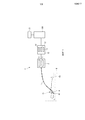
фиг. 1 - схематичное примерное представление варианта осуществления ультразвукового считывающего устройства для считывания объекта;FIG. 1 is a schematic illustration of an embodiment of an ultrasonic reader for reading an object;
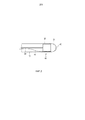
фиг. 2 - схематичное примерное представление наконечника катетера ультразвукового считывающего устройства;FIG. 2 is a schematic illustration of a catheter tip of an ultrasound reader;
фиг. 3 - схематичное примерное представление зависимости ультразвуковой энергии от глубины ткани и соответствующего ультразвукового сигнала;FIG. 3 is a schematic example representation of the dependence of ultrasonic energy on tissue depth and the corresponding ultrasonic signal;
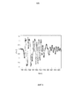
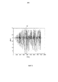
фиг. 4 - схематичное примерное представление нефильтрованной А-линии;FIG. 4 is a schematic illustration of an unfiltered A line;
фиг. 5 - иллюстрация влияния повышающей дискретизации и фильтрации;FIG. 5 is an illustration of the effect of upsampling and filtering;
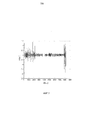
фиг. 6 - схематичное примерное представление корректирующего сигнала;FIG. 6 is a schematic representation of a correction signal;
фиг. 7 - схематичное примерное представление скорректированной А-линии;FIG. 7 is a schematic illustration of a corrected A-line;
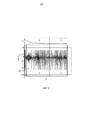
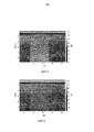
фиг. 8 - ультразвуковое изображение в М-режиме, содержащее нескорректированные А-линии;FIG. 8 is an ultrasound image in M-mode containing unadjusted A-lines;
фиг. 9 - ультразвуковое М-изображение, содержащее скорректированные А-линии;FIG. 9 is an ultrasound M image containing corrected A-lines;
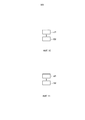
фиг. 10 - блок-схема примерной последовательности операций, представляющая вариант осуществления способа фильтрации для фильтрации ультразвукового сигнала;FIG. 10 is a flowchart of an exemplary flowchart representing an embodiment of a filtering method for filtering an ultrasonic signal;
фиг. 11 - блок-схема примерной последовательности операций, представляющая вариант осуществления способа ультразвукового считывания для считывания объекта.FIG. 11 is a flowchart of an exemplary flowchart representing an embodiment of an ultrasonic reading method for reading an object.
ОСУЩЕСТВЛЕНИЕ ИЗОБРЕТЕНИЯDETAILED DESCRIPTION OF THE INVENTION
На фиг. 1 схематично показано примерное ультразвуковое считывающее устройство 1 для считывания объекта 4. В этом варианте осуществления объект 4 является сердцем человека 13, расположенного на столе 60. В частности, объектом является сердечная ткань стенки сердца 4. Ультразвуковое считывающее устройство 1 содержит катетер 12 с наконечником 40 катетера, который схематически и примерно показан более подробно на фиг. 2.In FIG. 1 schematically shows an exemplary
Наконечник 40 катетера содержит ультразвуковой модуль 32 для генерации ультразвукового сигнала, зависящего от ультразвуковых волн, принятых от объекта 4. Наконечник 40 катетера также содержит дополнительный модуль 31, являющийся электрическим модулем. Электрический модуль 31 выполнен с возможностью подачи электрической энергии на сердечную ткань.The
Ультразвуковой модуль 32 управляется ультразвуковым модулем 5 управления, причем ультразвуковой модуль 32 и ультразвуковой модуль 5 управления выполнены с возможностью посылки ультразвуковых импульсов в сердечную ткань, чтобы принимать серию динамических эхо-сигналов после отражения ультразвуковых импульсов сердечной тканью, и генерировать ультразвуковой сигнал, зависящий от принятой серии динамических эхо-сигналов. Ультразвуковой модуль 32 подсоединяется к ультразвуковому устройству 5 управления через электрическое соединение 23.The
Подающий электрическую энергию модуль 31 является абляционным электродом для приложения РЧ энергии к сердечной ткани, причем абляционный электрод 31 подсоединен к вспомогательному устройству 6 управления через электрическое соединение 41, являющееся, например, кабелем для управления абляционным электродом 31. Абляционный электрод 31 является колпачковым электродом, расположенным на наконечнике 40 катетера 12 и содержит переднее центральное отверстие 42, позволяющее ультразвуковому элементу 32 осуществлять считывание сердечной ткани через отверстие 42.The electric
Вспомогательный модуль 6 управления и ультразвуковой модуль 5 управления интегрированы в устройство 7 управления. В других вариантах осуществления эти модули управления могут быть отдельными модулями управления. Кроме того, вспомогательный модуль 6 управления предпочтительно выполняется дополнительно с возможностью управления наведением наконечника 40 и/или промыванием. В этом случае катетер дополнительно содержит наводящий модуль и/или промывающий модуль, соответственно, которые не показаны на фиг. 1 и фиг. 2. Разные функции управления могут выполняться любым числом модулей управления, например, одним модулем управления или же двумя или более чем двумя модулями управления.The auxiliary control module 6 and the
Модуль 7 управления выполнен с возможностью управления ультразвуковым модулем 32 и электрическим модулем 31 одновременно, при этом генерируемый ультразвуковой сигнал испытывает воздействие, оказываемое электрическим модулем 31, то есть в этом варианте осуществления, оказываемое прилагаемой РЧ энергией. Генерируемый ультразвуковой сигнал 19 схематически и примерно показан на фиг. 3.The control module 7 is configured to control the
В верхней части фиг. 3 схематично и в качестве примера показан график зависимости ультразвуковой энергии Е от глубины d ткани. В нижней части фиг. 3 показан генерируемый ультразвуковой сигнал 19. В частности, ультразвуковой сигнал 19, показанный в нижней части фиг. 3, является А-линией, в которой амплитуда показана зависящей от глубины d ткани. Ультразвуковая энергия Е уменьшается с увеличением глубины ткани вследствие поглощения и рассеяния ее сердечной тканью. Первая часть А ультразвукового сигнала 19 соответствует ультразвуковой энергии Е, которая больше 0. Поэтому, первая часть А содержит информацию о сердечной ткани, от которой был принят ультразвуковой сигнал 19. Вторая часть В ультразвукового сигнала 19 соответствует ультразвуковой энергии Е, по существу равной 0. Поэтому вторая часть В ультразвукового сигнала 19 не содержит информации об объекте. В этом примере первая часть А содержит информацию о ткани, которая затенена радиочастотными (РЧ) помехами, а вторая часть В не содержит информации о ткани вследствие поглощения и рассеяния ультразвуковой энергии, и во второй части В видимы только РЧ помехи. К обеим частям ультразвукового сигнала было применено зависящее от времени усиление (TGC). Первая часть 43 ультразвукового сигнала 19 обусловливается прямым вызовом преобразователя.At the top of FIG. 3 schematically and as an example, a graph of ultrasonic energy E versus tissue depth d is shown. At the bottom of FIG. 3 shows the generated ultrasonic signal 19. In particular, the ultrasonic signal 19 shown at the bottom of FIG. 3 is an A-line in which the amplitude is shown depending on the depth d of the tissue. Ultrasonic energy E decreases with increasing tissue depth due to absorption and scattering by its cardiac tissue. The first part A of the ultrasonic signal 19 corresponds to ultrasonic energy E, which is greater than 0. Therefore, the first part A contains information about the heart tissue from which the ultrasonic signal 19 was received. The second part B of the ultrasonic signal 19 corresponds to ultrasonic energy E, essentially equal to 0. Therefore, the second part B of the ultrasonic signal 19 does not contain information about the object. In this example, the first part A contains information about tissue that is obscured by radio frequency (RF) interference, and the second part B does not contain information about tissue due to absorption and scattering of ultrasonic energy, and only RF interference is visible in the second part B. A time-dependent gain (TGC) was applied to both parts of the ultrasound signal. The
Ультразвуковое считывающее устройство 1 дополнительно содержит фильтрующее устройство 15 для фильтрации генерируемого ультразвукового сигнала 19. Фильтрующее устройство 15 содержит модуль 16 обеспечения основной частоты для обеспечения основной частоты (частоты основной гармоники) воздействия, оказываемого РЧ абляционным электродом 31. В этом варианте осуществления модуль 16 обеспечения основной частоты выполнен с возможностью определения основной частоты посредством кросс-корреляции двух последовательных подчастей второй части В ультразвукового сигнала 19. Предпочтительно, модуль 16 обеспечения основной частоты выполнен с возможностью аппроксимации результата кросс-корреляции параболической функцией и определения основной частоты в зависимости от максимума параболической функции аппроксимации. Это будет более подробно описано ниже.The
Полагается, что ультразвуковой сигнал содержит несколько выборок Sk, при этом первая подчасть Х может быть определена следующим уравнением:It is believed that the ultrasonic signal contains several samples S k , while the first sub-part X can be determined by the following equation:
X=[Si…j] (1)X = [S i ... j ] (1)
где i означает первую выборку из второй части B ультразвукового сигнала, которая в этом примере может быть равна 3000 (i=3000), и гдеwhere i means the first sample from the second part B of the ultrasonic signal, which in this example may be 3000 (i = 3000), and where
j=i+N (2)j = i + N (2)
Переменная N выбирается так, чтобы она содержала по меньшей мере один полный РЧ цикл, который определяется вспомогательным модулем 6 управления, в частности, РЧ генератором вспомогательного модуля 5 управления, и в этом варианте осуществления составляет 460 кГц±20 кГц. Кроме того, в этом варианте осуществления ультразвуковой сигнал принимается на частоте 200 МГц. Таким образом, N=454 (200 МГц разделенные 440 кГц) выборки составляют один РЧ цикл. Поэтому, переменные могут быть определены как i=3000 и j=3454. Конечно, если в другом примере РЧ, определяемая РЧ генератором, будет другой, число выборок, составляющих полный РЧ цикл, должно быть соответственно изменено.The variable N is selected so that it contains at least one complete RF cycle, which is determined by the auxiliary control module 6, in particular, the RF generator of the
Вторая последующая подчасть второй части В ультразвукового сигнала может быть определена следующим уравнением:The second subsequent sub-part of the second part In the ultrasonic signal can be determined by the following equation:
Y=[Sk…l], (3)Y = [S k ... l ], (3)
где k=j+l и (4)where k = j + l and (4)
l=k+N (5)l = k + N (5)
Следующие друг за другом подчасти Х и Y подвергаются кросс-корреляции, аппроксимирующее параболическое уравнение подбирается к результату кросс-корреляции, и максимум параболического уравнения аппроксимации определяет основную частоту.Subsequent X and Y subparts are cross-correlated, the approximating parabolic equation is matched to the cross-correlation result, and the maximum of the parabolic approximation equation determines the fundamental frequency.
Другими словами, для каждой А-линии может быть извлечена основная РЧ частота посредством кросс-корреляции двух последовательных частей X=[St-2W-l…t-W-l] и Y=[St-W…t], при этом размер W окна оптимизируется, чтобы содержать по меньшей мере один полный период РЧ помех. Предварительное знание частоты и РЧ полосы частот, которое может быть получено из спецификации РЧ генератора, может повысить скорость вычисления кросс-корреляции, поскольку может быть определен адекватный размер окна, как описано выше. Переменная t предпочтительно выбирается так, что t-2W определяет выборку, представляющую только РЧ помехи, и не содержащую отражений от ткани.In other words, for each A-line, the main RF frequency can be extracted by cross-correlation of two consecutive parts X = [S t-2W-l ... tWl ] and Y = [S tW ... t ], while the window size W is optimized, to contain at least one complete period of RF interference. A preliminary knowledge of the frequency and the RF frequency band, which can be obtained from the specification of the RF generator, can increase the cross-correlation calculation speed, since an adequate window size can be determined, as described above. The variable t is preferably selected such that t-2W defines a sample representing only RF interference and not containing tissue reflections.
В другом варианте осуществления подчасти, определенные уравнениями (1) и (3), могут быть повышающим образом дискретизированы, и дискретизированные с повышением подчасти могут быть подвергнуты кросс-корреляции. В этом случае основная РЧ частота предпочтительно определяется непосредственно из результата кросс-корреляции, без выполнения параболической аппроксимации.In another embodiment, the sub-parts defined by equations (1) and (3) can be up-sampled, and the up-sampled parts can be cross-correlated. In this case, the primary RF frequency is preferably determined directly from the cross-correlation result, without performing a parabolic approximation.
Фильтрующее устройство 15 дополнительно содержит модуль 17 определения корректирующего сигнала для определения корректирующего сигнала, указывающего влияние электрического модуля 31 на ультразвуковой сигнал 19, исходя из второй части В ультразвукового сигнала 19. В частности, модуль 17 определения корректирующего сигнала выполнен с возможностью определения подчасти второй части ультразвукового сигнала, которая соответствует по меньшей мере одному циклу влияния, оказываемого электрическим модулем 31, в зависимости от обеспеченной основной частоты, и определения последовательности определенных подчастей второй части ультразвукового сигнала в качестве корректирующего сигнала. Подчасть второй части может рассматриваться как шаблонная РЧ структура из А-линии. Эта шаблонная РЧ структура выбирается таким образом, чтобы она обязательно находилась в зоне А-линии, в которой присутствуют только РЧ помехи и нет отражений от ткани. Например, при центральной частоте ультразвука в 20 МГц шаблонная РЧ структура может быть выбрана на относительно большой глубине ткани, превышающей, например, 15 мм.The
Модуль 16 определения корректирующего сигнала предпочтительно выполняется с дополнительной возможностью повышающей дискретизации шаблонной РЧ структуры с коэффициентом 2, и применения двунаправленного взаимного БИХ-фильтра, который является интерполяционным фильтром, к дискретизированной с повышением шаблонной РЧ структуре. Такие повышающая дискретизация и фильтрация двунаправленным взаимным БИХ-фильтром предпочтительно выполняются несколько раз, в частности, пять раз. Повышающая дискретизация предпочтительно выполняется путем вставления 0 между каждой парой выборок шаблонной РЧ структуры, то есть шаблонной РЧ структуры. Двунаправленная взаимная БИХ-фильтрация, также известная как рекурсивная фильтрация в половинной полосе частот или рекурсивная фильтрация в М-полосе частот, описана, например, в работе “Эффективность многоскоростной и комплексной цифровой обработки сигналов”, A.W.M. van den Enden, ISBN 90-6674-650-5, глава 7.1, которая включена сюда посредством ссылки.The correction
Двунаправленный взаимный БИХ-фильтр выполнен таким образом, что не наблюдается искажение информации и не оказывается влияние на шаблонную РЧ структуру. Повышающая дискретизация с коэффициентом 2 на одном этапе повышающей дискретизации, после которого выполняется фильтрация, является предпочтительной, потому что ее легче реализовать на цифровых сигнальных процессорах (ЦСП), что может быть очень полезным при интеграции в микросхему. В другом варианте осуществления повышающая дискретизация может также выполняться с другим коэффициентом умножения и/или может использоваться другой интерполяционный фильтр.The bidirectional mutual IIR filter is designed in such a way that there is no information distortion and no effect on the template RF structure. Upsampling with a coefficient of 2 at one stage of upsampling, after which filtering is performed, is preferable because it is easier to implement on digital signal processors (DSPs), which can be very useful when integrated into a microcircuit. In another embodiment, upsampling may also be performed with a different multiplication factor and / or a different interpolation filter may be used.
В описанном выше примере с дискретизацией на частоте 200 МГц полный РЧ цикл имеет 454 выборок, если полагается, что РЧ частота равна 460 кГц+/-20 кГц. Однако РЧ частота и ее гармоники могут изменяться во время абляции. Такое изменение не обязательно будет представлено целым числом выборок, то есть, например, РЧ частота может изменяться от 460000,000 Гц до 460000,005 Гц в пределах двух последовательных РЧ циклов внутри одной А-линии. Поэтому шаблон может не точно согласовываться с соответствующей подчастью части А, если корректирующий сигнал используется для коррекции первой части А. Поэтому для того чтобы улучшить точность согласования, может быть обеспечен небольшой сдвиг в выборках. Однако, если повышающая дискретизация выполняется с коэффициентом повышения, равным, например, 16, как описано выше, разрешающая способность увеличивается до 0,0625 выборок, то есть, если до повышающей дискретизации расстояние между последовательными выборками было равно единице, то теперь это расстояние равно 0,0625. Было обнаружено, что такое разрешение достаточно для компенсации изменения РЧ частоты внутри одной А-линии.In the example described above with sampling at a frequency of 200 MHz, the full RF cycle has 454 samples if it is assumed that the RF frequency is 460 kHz +/- 20 kHz. However, the RF frequency and its harmonics may change during ablation. Such a change will not necessarily be represented by an integer number of samples, that is, for example, the RF frequency can vary from 460,000,000 Hz to 460,000.005 Hz within two consecutive RF cycles within the same A-line. Therefore, the pattern may not exactly match the corresponding subpart of part A if the correction signal is used to correct the first part A. Therefore, in order to improve the accuracy of matching, a small shift in the samples can be provided. However, if upsampling is performed with an upscaling factor equal to, for example, 16, as described above, the resolution is increased to 0.0625 samples, that is, if the distance between successive samples was equal to one before upsampling, now this distance is 0 , 0625. It was found that such a resolution is sufficient to compensate for changes in the RF frequency within one A-line.
Модуль 17 определения корректирующего сигнала может быть дополнительно выполнен с возможностью пересчета РЧ основной частоты в дробную частоту в выборках. Например, если положение максимума полиномиально интерполированной корреляции известно из описанной выше аппроксимирующей процедуры, основная РЧ частота для соответствующей А-линии известна. Вычисление может выполняться таким образом, чтобы определенная РЧ основная частота укладывалась в повышающую дискретизацию с предпочтительным коэффициентом 16, которая достигалась, как описано выше, выполнением повышающей дискретизации с коэффициентом два четыре раза. РЧ основная частота может быть пересчитана в ближайшую выборку, то есть РЧ основная частота может быть округлена до ближайшей выборки. Например, если определенная РЧ основная частота составляет 454,05 выборок, то она может быть пересчитана в 454,0625 выборок.The correction signal determination module 17 may be further configured to convert the RF fundamental frequency to a fractional frequency in the samples. For example, if the position of the maximum of the polynomially interpolated correlation is known from the approximating procedure described above, the main RF frequency for the corresponding A-line is known. The calculation can be performed in such a way that a certain RF fundamental frequency fits into the upsampling with a preferred coefficient of 16, which is achieved, as described above, by performing upsampling with a factor of two four times. The RF base frequency can be recalculated to the nearest sample, that is, the RF main frequency can be rounded to the nearest sample. For example, if a specific RF base frequency is 454.05 samples, then it can be recalculated into 454.0625 samples.
Модуль 5 управления ультразвуковым модулем предпочтительно выполняется с возможностью приложения зависящего от времени усиления к ультразвуковому сигналу. Модуль 17 определения корректирующего сигнала, поэтому, предпочтительно выполняется с возможностью приложения того же самого зависящего от времени усиления к корректирующему сигналу. Поэтому, модуль 17 определения корректирующего сигнала предпочтительно выполняется с возможностью компенсации корректирующего сигнала, то есть дискретизированных с повышением и отфильтрованных шаблонных РЧ структур, для коррекции амплитуды.The ultrasound
Фильтрующее устройство 15 дополнительно содержит модуль 17 коррекции для коррекции первой части А ультразвукового сигнала 19 на основе определенного корректирующего сигнала, чтобы отфильтровать влияние электрического модуля 31 из ультразвукового сигнала 19. В частности, модуль 17 коррекции выполнен с возможностью вычитания определенного корректирующего сигнала из первой части А ультразвукового сигнала 19.The
Вычитание корректирующего сигнала, то есть последовательности дискретизированных с повышением РЧ структур, из первой части А ультразвукового сигнала может быть описано следующим уравнением:Subtraction of the correction signal, that is, the sequence of the structures sampled with increasing RF, from the first part A of the ultrasonic signal can be described by the following equation:
![]()
![]()
гдеWhere
![]()
![]()
В уравнении (6) ![]()
![]()
![]()
![]()
delay,delay+U,delay+2U, …, UR+delay,delay, delay + U, delay + 2U, ..., UR + delay,
где U означает общий коэффициент повышающей дискретизации, который в приведенном выше примере с четырехкратным осуществлением повышающей дискретизации с коэффициентом 2 равен 16. Таким образом, из шаблонной РЧ структуры берется только каждая U-я выборка, в соответствии с общим коэффициентом U повышающей дискретизации.where U means the total upsampling coefficient, which in the above example with four times upsampling with a factor of 2 is 16. Thus, only every Uth sample is taken from the template RF structure, in accordance with the general upsampling coefficient U.
При этом корректирующий сигнал вычитается из исходных данных А-линии, содержащих как отраженные от ткани ультразвуковые данные, так и РЧ помехи.In this case, the correction signal is subtracted from the initial A-line data containing both ultrasound data reflected from the tissue and RF interference.
На фиг. 4 схематично и в качестве примера показана одна А-линия с РЧ помехами. На фиг. 5 схематично и в качестве примера показана подчасть второй части В для иллюстрации повышающей дискретизации и фильтрации. Исходные выборки обозначены кружками, а выборки с повышающей дискретизацией обозначены крестиками. Подчасть, показанная на фиг. 4, содержит около 2000/16 выборок по отношению к исходной дискретизации, если общий коэффициент повышающей дискретизации равен 16, то есть, около четверти шаблона, имеющего 454 выборки, по отношению к исходной дискретизации в описанном выше варианте осуществления. На фиг. 5 высокая амплитуда между метками 2000 и 3000 представляет собой половину действительного цикла РЧ помех. Поскольку РЧ помехи возникают при пересечениях нуля, и РЧ цикл является синусоидой, существуют две почти одинаковые, но не полностью идентичные РЧ помехи на РЧ цикл.In FIG. 4 schematically and as an example, one A-line with RF interference is shown. In FIG. 5 schematically and as an example, a sub-part of the second part B is shown to illustrate upsampling and filtering. The original samples are indicated by circles, and the samples with upsampling are indicated by crosses. The subpart shown in FIG. 4 contains about 2000/16 samples with respect to the original sampling if the total upsampling ratio is 16, that is, about a quarter of the pattern having 454 samples with respect to the original sampling in the above embodiment. In FIG. 5, the high amplitude between the 2000 and 3000 marks represents half the actual RF interference cycle. Because RF interference occurs at zero crossings, and the RF cycle is a sinusoid, there are two almost identical but not completely identical RF interference to the RF cycle.
На фиг. 6 схематично и в качестве примера показана восстановленная структура РЧ помех, то есть последовательность РЧ шаблонов, соответствующих А-линии, которая может быть вычтена из А-линии. Формирование последовательности РЧ шаблонов и вычитание предпочтительно выполняется только для первой части А ультразвукового сигнала. Одна шаблонная РЧ структура обведена рамкой 45. Последовательные структуры, образующие корректирующий сигнал, показанный на фиг. 6, изменяются, поскольку разные выборки дискретизированных с повышением шаблонных РЧ структур используются для вычитания в соответствии с уравнением (6).In FIG. 6 schematically and by way of example shows the reconstructed structure of the RF interference, that is, a sequence of RF patterns corresponding to the A-line, which can be subtracted from the A-line. The formation of the sequence of RF patterns and subtraction is preferably performed only for the first part And the ultrasonic signal. One template RF structure is circled by
Корректирующий сигнал вычитается в каждый момент времени в А-линии, по меньшей мере в первой части А в А-линии, где возникает РЧ помеха. Результирующие А-линии могут сцепляться друг с другом, образуя ультразвуковое изображение в М-режиме. На фиг. 8 показано такое ультразвуковое изображение в М-режиме без выполнения описанной выше коррекции, а на фиг. 9 показано ультразвуковое изображение в М-режиме после выполнения коррекции. Как можно ясно увидеть, в ультразвуковом изображении М-режима, показанном на фиг. 9, РЧ помехи уменьшены.A correction signal is subtracted at each time point in the A-line, at least in the first part A in the A-line, where RF interference occurs. The resulting A-lines can interlock with each other, forming an ultrasound image in the M-mode. In FIG. 8 shows such an ultrasound image in M-mode without performing the correction described above, and FIG. 9 shows an ultrasound image in M-mode after performing the correction. As can be clearly seen, in the ultrasound image of the M-mode shown in FIG. 9, RF interference is reduced.
Согласно фиг. 1, ультразвуковое считывающее устройство 1 дополнительно содержит модуль 103 определения воздействия на объект для определения воздействия приложенной к объекту 4 энергии в зависимости от ультразвукового считывания объекта 4. В частности, модуль 31 приложения энергии выполнен с возможностью абляции объекта 4, при этом модуль 103 определения воздействия на объект выполнен с возможностью определения глубины абляции, которая может также рассматриваться как граница разрушения, в зависимости от ультразвукового считывания объекта 4. Поэтому модуль 103 определения воздействия на объект выполнен с возможностью приема ультразвукового сигнала от ультразвукового модуля 5 и определения глубины абляции в зависимости от принятого ультразвукового сигнала. Определение глубины абляции, а также толщины стенки сердца, основанное на ультразвуковом изображении в М-режиме, описано, например, в публикации WO 2010/082146 A1, включенной сюда посредством ссылки. Например, модуль 103 определения воздействия на объект может быть выполнен с возможностью определения положения передней поверхности и задней поверхности стенки сердца по ультразвуковому сигналу, и определения толщины стенки сердца в зависимости от этих положений, то есть, соответствующие положения по глубине могут быть вычтены друг из друга, чтобы определить толщину стенки сердца.According to FIG. 1, the
Вспомогательный модуль 6 управления предпочтительно выполняется с возможностью управления абляционным электродом 31 в зависимости от глубины абляции, определенной модулем 103 определения воздействия на объект. Например, величина и/или продолжительность приложения абляционной энергии к объекту 4 контролируется в зависимости от определенной глубины абляции. В частности, модуль 103 определения воздействия на объект может быть выполнен с возможностью определения толщины стенки сердца, и затем вспомогательный модуль 6 управления может быть выполнен с возможностью управления абляционным электродом 31 в зависимости от этой определенной толщины и определенной глубины абляции. Предпочтительно вспомогательный модуль 6 абляции выполняется с возможностью абляции ткани стенки сердца вплоть до достижения желаемой степени трансмуральности (пронизания) стенки сердца, в частности до тех пор, пока результирующее разрушение не станет трансмуральным.The auxiliary control unit 6 is preferably configured to control the
Предпочтительно, ультразвуковое считывающее устройство 1 выполняется с возможностью определения толщины стенки сердца и глубины абляции неоднократно, при этом модуль 103 определения глубины абляции выполняется с возможностью повторного определения степени трансмуральности абляции по определенной толщине и определенной глубине абляции. В частности, ультразвуковое считывающее устройство 1 выполняется с возможностью прекращения процедуры абляции, если была достигнута заданная степень трансмуральности абляции.Preferably, the
Ультразвуковое считывающее устройство 1 дополнительно содержит модуль 20 визуализации для визуального наблюдения глубины абляции. В частности, модуль 20 визуализации выполнен с возможностью визуального наблюдения за продвижением к границе разрушения. Визуализация предпочтительно осуществляется в реальном времени. Модуль 20 визуализации предпочтительно выполняется с возможностью показа ультразвукового сигнала, продвижения абляции, то есть границы разрушения, и положений передней и задней поверхностей.The
Ультразвуковое считывающее устройство 1 предпочтительно используется в сочетании с системой для определения положения и/или ориентации катетера 12, в частности, внутри объекта 4, преимущественно внутри сердца человека или животного. В этом варианте осуществления система формирования изображений, подобная магнитно-резонансной системе, используется для определения положения и/или ориентации катетера. Такая система формирования изображений обведена пунктирной линией 8 на фиг. 1. Катетер 12, в частности, наконечник катетера, может содержать элементы для облегчения определения ориентации и/или положения катетера посредством использования системы 8 формирования изображений. Например, наконечник катетера может содержать следящую катушку, если наконечник катетера используется в составе магнитно-резонансной системы формирования изображений, или элементы, которые могут быть идентифицированы на рентгеновском изображении и которые имеют такую форму, что становится возможным определение положения и/или ориентации катетера при использовании рентгеноскопической системы. Наконечник катетера может также содержать датчик положения для определения положения и/или ориентации катетера 12, в частности, наконечника катетера внутри объекта 4.The
Система позиционирования позволяет пользователю располагать катетер 12 внутри сердца или, более в частности, в левом предсердии пациента. Пользователь может располагать катетер 12 в точном положении относительно стенки сердца, чтобы измерить толщину стенки, используя ультразвуковой сигнал, генерируемый ультразвуковым модулем 11, и модуль 103 определения воздействия на объект. Используя определенное положение катетера, можно отображать на дисплее толщину стенки сердца в изображении сердца. После сбора результатов достаточного числа измерений, то есть после определения толщины сердца в разных местоположениях на стенке сердца, пользователь может установить стратегию абляции, включающую в себя требуемую мощность и продолжительность в зависимости от определенной толщины стенки сердца. Можно также использовать наконечник катетера для отслеживания ранее выполненных абляционных разрушений в целях верификации. Могут быть определены целостность и глубина разрушений, которые были созданы.The positioning system allows the user to position the
Далее будет описан примерный вариант осуществления способа фильтрации для фильтрации ультразвукового сигнала со ссылками на блок-схему последовательности операций, изображенную на фиг. 10.Next, an exemplary embodiment of a filtering method for filtering an ultrasonic signal will be described with reference to the flowchart shown in FIG. 10.
Ультразвуковой сигнал может подвергаться воздействию электрического модуля и содержать первую часть, содержащую информацию об объекте, от которого был принят ультразвуковой сигнал, и вторую часть, не содержащую принятой информации об объекте. На этапе 201 корректирующий сигнал, указывающий влияние электрического модуля на ультразвуковой сигнал, определяется из второй части ультразвукового сигнала, модулем определения корректирующего сигнала. На этапе 202 первая часть ультразвукового сигнала корректируется корректирующим модулем на основе определенного корректирующего сигнала, чтобы отфильтровать влияние электрического модуля из ультразвукового сигнала.The ultrasonic signal may be exposed to an electrical module and contain a first part containing information about the object from which the ultrasonic signal was received, and a second part not containing received information about the object. In
На фиг. 11 показана блок-схема последовательности операций, иллюстрирующая примерный вариант осуществления способа ультразвукового считывания для считывания объекта.In FIG. 11 is a flowchart illustrating an example embodiment of an ultrasonic reading method for reading an object.
На этапе 301 генерируется ультразвуковой сигнал в зависимости от ультразвуковых волн, принятых от объекта ультразвуковым модулем, причем ультразвуковой модуль и дополнительный модуль, являющийся электрическим модулем, включены в состав катетера, причем ультразвуковой модуль и электрический модуль работают одновременно, и при этом ультразвуковой сигнал подвергается воздействию электрического модуля и включает в себя первую часть, содержащую информацию об объекте, от которого был принят ультразвуковой сигнал, и вторую часть, не содержащую информацию об объекте. На этапе 302 выполняются операции фильтрации способа фильтрации, описанные выше со ссылкой на фиг. 10, при этом модуль определения корректирующего сигнала определяет корректирующий сигнал, указывающий влияние электрического модуля на генерируемый ультразвуковой сигнал, из второй части ультразвукового сигнала, и при этом корректирующий модуль корректирует первую часть ультразвукового сигнала, основываясь на определенном корректирующем сигнале, чтобы отфильтровать влияние электрического модуля из первой части ультразвукового сигнала.At
Фильтрующее устройство предпочтительно обеспечивает цифровой фильтр, основанный на преобразовании частоты выборок, для фильтрации РЧ без влияния на ультразвуковой сигнал. Этот цифровой фильтр может применяться в реальном времени, обеспечивая тем самым визуализацию невозмущенных ультразвуковых сигналов, которые могут обрабатываться и/или наблюдаться во время, например, медицинской процедуры.The filter device preferably provides a digital filter based on the conversion of the sampling frequency to filter the RF without affecting the ultrasonic signal. This digital filter can be applied in real time, thereby providing visualization of unperturbed ultrasonic signals that can be processed and / or observed during, for example, a medical procedure.
При объединении абляции с ультразвуковым мониторингом катетера выполняется как ультразвуковое считывание, так и абляция. Хотя разные соединительные провода используются для обоих сигналов, РЧ сигналы, имеющие очень высокую мощность, могут оказывать непрямое воздействие через связь на провода с ультразвуковыми сигналами. Такое воздействие может возникать внутри катетера через емкостную связь из-за неэффективного экранирования или внутри сердца вследствие кондуктивной связи, например, через кровь и/или соляную промывающую текучую среду. Обычно РЧ частоты в диапазоне около от 450 до 500 кГц лежат за пределами полосы частот, представляющей интерес при формировании ультразвуковых изображений, которая в общем случае находится между около 1 и 50 МГц. Однако есть гармоники и помехи, которые могут привести к интерференционным картинам с постоянными интервалами в ультразвуковом сигнале, когда синусоидальная кривая пересекает уровень постоянного тока (DC). Поэтому ультразвуковой сигнал с малой амплитудой может быть замаскирован РЧ помехами.When combining ablation with ultrasound monitoring of the catheter, both ultrasound reading and ablation are performed. Although different connecting wires are used for both signals, RF signals having very high power can have an indirect effect through communication on the wires with ultrasonic signals. Such an effect can occur inside the catheter via capacitive coupling due to inefficient shielding or inside the heart due to conductive coupling, for example, through blood and / or saline flushing fluid. Typically, the RF frequencies in the range of about 450 to 500 kHz lie outside the frequency band of interest in the formation of ultrasound images, which generally lies between about 1 and 50 MHz. However, there are harmonics and interferences that can lead to interference patterns at constant intervals in the ultrasonic signal when the sine curve crosses the direct current (DC) level. Therefore, an ultrasonic signal with a small amplitude can be masked by RF interference.
При медицинском формировании изображений ультразвуковые преобразователи разных частот используются вплоть до частоты 50 МГц. Для отслеживания разрушений при интеграции РЧ абляции и ультразвукового отслеживания предпочтительно используются ультразвуковые преобразователи с центральной частотой в диапазоне около от 20 до 30 МГц. Для того чтобы получить высокое разрешение, ультразвуковые сигналы принимаются на высокой частоте, равной, например, 200 МГц на А-линию. Выборки из А-линии обычно производятся при частоте 20-100 Гц, чтобы получить изображение в М-режиме, однако возможна также и более высокая частота выборок, например до 1 кГц. Несколько разных способов фильтрации могут использоваться для фильтрации РЧ, но они должны работать в реальном времени, то есть должна быть возможной обработка многих выборок за секунду. Описанное выше фильтрующее устройство может быть выполнено с возможностью удаления РЧ помех из ультразвукового сигнала в реальном времени, не влияя на качество ультразвукового сигнала. Кроме того, соответствующий алгоритм предпочтительно оптимизирован для запуска на конкретных аппаратных микросхемах (чипах), в частности, на процессорах цифровой обработки сигналов (DSP).In medical imaging, ultrasound transducers of different frequencies are used up to a frequency of 50 MHz. Ultrasound transducers with a center frequency in the range of about 20 to 30 MHz are preferably used to track damage when integrating RF ablation and ultrasound tracking. In order to obtain high resolution, ultrasonic signals are received at a high frequency equal to, for example, 200 MHz per A-line. Samples from the A-line are usually made at a frequency of 20-100 Hz to obtain an image in the M-mode, however, a higher sampling frequency is also possible, for example, up to 1 kHz. Several different filtering methods can be used to filter RF, but they should work in real time, that is, it should be possible to process many samples per second. The filtering device described above can be configured to remove RF interference from an ultrasonic signal in real time without affecting the quality of the ultrasonic signal. In addition, the corresponding algorithm is preferably optimized to run on specific hardware circuits (chips), in particular, on digital signal processing (DSP) processors.
Хотя в описанных выше вариантах осуществления корректирующий сигнал используется для коррекции первой части А ультразвукового сигнала, корректирующий сигнал может быть также использован для коррекции полного ультразвукового сигнала, включающего в себя первую часть А и вторую часть В.Although in the above-described embodiments, the correction signal is used to correct the first part A of the ultrasonic signal, the correction signal can also be used to correct the complete ultrasonic signal including the first part A and the second part B.
Хотя в описанных выше вариантах осуществления были описаны конкретные этапы обработки для обработки РЧ шаблонных структур, в других вариантах осуществления могут также выполняться другие этапы обработки. Например, вместо интерполяционного БИХ-фильтра в качестве фильтра с частичной задержкой может использоваться фильтр с конечной импульсной характеристикой (КИХ-фильтр). Кроме того, может быть также использован стандартный интерполяционный БИХ-фильтр, который не является двунаправленным взаимным фильтром.Although specific processing steps for processing RF template structures have been described in the above embodiments, other processing steps may also be performed in other embodiments. For example, instead of an interpolation IIR filter, a filter with a finite impulse response (FIR filter) can be used as a filter with partial delay. In addition, a standard IIR interpolation filter, which is not a bidirectional reciprocal filter, can also be used.
Хотя в описанных выше вариантах осуществления электрический модуль, который оказывает влияние на ультразвуковой сигнал, является абляционным электродом, в других вариантах осуществления электрический модуль может быть и другим модулем, таким как модуль формирования рентгеновских изображений или электрический нож, который может вызывать помехи и/или шумы.Although in the above-described embodiments, the electrical module that affects the ultrasound signal is an ablation electrode, in other embodiments, the electrical module may be another module, such as an X-ray imaging module or an electric knife, which may cause interference and / or noise .
Ультразвуковое считывающее устройство и фильтрующее устройство предпочтительно выполняются с возможностью использования визуализации ткани во время лечения, например, аритмии сердца или абляции опухоли, причем РЧ абляция и ультразвуковая визуализация объединяются в одном катетере или в одной игле. Алгоритм, реализуемый в фильтрующем устройстве, может быть полезным для удаления также других помех с другими характеристиками, таких как РЧ помехи, из представляющих интерес сигналов.The ultrasound reader and filter device are preferably configured to use tissue imaging during treatment, for example, cardiac arrhythmias or tumor ablation, wherein RF ablation and ultrasound imaging are combined in one catheter or in one needle. The algorithm implemented in the filtering device may be useful for removing also other interference with other characteristics, such as RF interference, from the signals of interest.
Хотя ультразвуковое считывающее устройство предпочтительно выполняется как катетер для отслеживания сердечной абляции, который может быть использован в сочетании с генератором РЧ сигналов, ультразвуковое считывающее устройство может быть также выполнено с возможностью считывания других объектов, подобных другим частям человека или животного, таким как другой орган или сосуды, или технического объекта, такого как трубопровод. Кроме того, вместо подачи РЧ энергии электрический модуль может быть также выполнен с возможностью подачи другой электрической энергии на объект.Although the ultrasound reader is preferably configured as a cardiac ablation catheter that can be used in combination with an RF signal generator, the ultrasound reader can also be configured to read other objects, like other parts of a person or animal, such as another organ or vessels , or a technical facility, such as a pipeline. In addition, instead of supplying RF energy, the electrical module can also be configured to supply other electrical energy to the object.
Хотя в варианте осуществления, описанном выше со ссылкой на фиг. 2, катетер содержит только электрический модуль, являющийся абляционным электродом, и ультразвуковой модуль, катетер может содержать дополнительные элементы, такие как дополнительные считывающие элементы и/или дополнительные элементы подачи энергии, элементы промывания и т.п.Although in the embodiment described above with reference to FIG. 2, the catheter contains only an electric module, which is an ablating electrode, and an ultrasonic module, the catheter may contain additional elements, such as additional sensing elements and / or additional energy supply elements, washing elements, etc.
Другие разновидности описанных вариантов осуществления могут быть поняты и осуществлены специалистами в данной области техники при практическом применении заявляемого изобретения, на основе изучения чертежей, описания и прилагаемых пунктов формулы изобретения.Other varieties of the described embodiments may be understood and practiced by those skilled in the art in the practice of the claimed invention, based on a study of the drawings, description and appended claims.
В пунктах формулы изобретения слово “содержащий” не исключает других элементов или этапов, а единственное число не исключает множественности.In the claims, the word “comprising” does not exclude other elements or steps, and the singular does not exclude plurality.
Один модуль или устройство может выполнять функции нескольких элементов, перечисленных в формуле изобретения. Простой факт того, что определенные показатели повторены во взаимно отличающихся зависимых пунктах формулы изобретения, не указывает на то, что сочетание двух этих показателей не может быть использовано, чтобы достичь преимуществ изобретения.One module or device can perform the functions of several elements listed in the claims. The simple fact that certain indicators are repeated in mutually different dependent dependent claims does not indicate that a combination of these two indicators cannot be used to achieve the advantages of the invention.
Вычисления, подобные вычислению основной РЧ частоты, определение корректирующего сигнала, коррекция первой части ультразвукового сигнала в зависимости от корректирующего сигнала и т.п., выполняемые одним или несколькими модулями или устройствами, могут выполняться любым другим числом модулей или устройств. Например, определение основной РЧ частоты, определение корректирующего сигнала, коррекция ультразвукового сигнала в зависимости от определенного корректирующего сигнала, определение, например, глубины абляции в зависимости от скорректированного абляционного сигнала и т.п., могут выполняться одним модулем или любым другим числом разных модулей. Вычисления и/или управление фильтрующим устройством в соответствии со способом фильтрации или управление ультразвуковым считывающим устройством в соответствии со способом ультразвукового считывания могут быть реализованы в виде средств программного кода компьютерной программы и/или как выделенных аппаратных средств.Calculations similar to calculating the primary RF frequency, determining the correction signal, correcting the first part of the ultrasonic signal depending on the correction signal, etc., performed by one or more modules or devices, can be performed by any other number of modules or devices. For example, determining the primary RF frequency, determining the correction signal, correcting the ultrasonic signal depending on the specific correction signal, determining, for example, the ablation depth depending on the corrected ablation signal, etc., can be performed by one module or any other number of different modules. Calculations and / or control of the filter device in accordance with the filtering method or control of the ultrasonic reader in accordance with the method of ultrasonic reading can be implemented in the form of software code of a computer program and / or as dedicated hardware.
Компьютерная программа может храниться/распространяться на подходящем носителе, таком как оптический носитель информации или твердотельный носитель, который поставляется вместе или как часть другого аппаратного обеспечения, но может также распространяться другим образом, например, через Интернет (Internet) или другие проводные или беспроводные телекоммуникационные системы.The computer program may be stored / distributed on a suitable medium, such as an optical storage medium or a solid state medium that is supplied together or as part of other hardware, but can also be distributed in other ways, for example, via the Internet or other wired or wireless telecommunication systems .
Любые ссылочные позиции в формуле изобретения не следует рассматривать как ограничивающие ее объем.Any reference position in the claims should not be construed as limiting its scope.
Изобретение относится к фильтрующему устройству для фильтрации ультразвукового сигнала, который подвергается воздействию электрического модуля и содержит первую часть, включающую в себя информацию об объекте, от которого был принят ультразвуковой сигнал, и вторую часть, не содержащую информацию об объекте. Модуль определения корректирующего сигнала определяет корректирующий сигнал, указывающий влияние электрического модуля на ультразвуковой сигнал, из второй части ультразвукового сигнала, а корректирующий модуль корректирует первую часть ультразвукового сигнала на основе определенного корректирующего сигнала, чтобы отфильтровать влияние электрического модуля из ультразвукового сигнала. Поскольку корректирующий сигнал указывает влияние электрического модуля, то когда этот корректирующий сигнал используется для коррекции ультразвукового сигнала, нежелательные помехи, видимые в нефильтрованном ультразвуковом сигнале, могут быть отфильтрованы.The invention relates to a filtering device for filtering an ultrasonic signal, which is exposed to an electrical module and contains a first part that includes information about the object from which the ultrasonic signal was received, and a second part that does not contain information about the object. The correction signal determination module determines a correction signal indicating the effect of the electric module on the ultrasonic signal from the second part of the ultrasonic signal, and the correction module corrects the first part of the ultrasonic signal based on the determined correction signal in order to filter out the effect of the electric module from the ultrasonic signal. Since the correction signal indicates the effect of the electrical module, when this correction signal is used to correct the ultrasonic signal, unwanted noise visible in the unfiltered ultrasonic signal can be filtered out.
Claims (15)
модуль (17) определения корректирующего сигнала, выполненный с возможностью определения корректирующего сигнала, указывающего влияние электрического модуля на ультразвуковой сигнал (19), из второй части (В) ультразвукового сигнала;
корректирующий модуль (18), выполненный с возможностью коррекции первой части (А) ультразвукового сигнала (19) на основе определенного корректирующего сигнала, чтобы отфильтровать влияние электрического модуля (31) из ультразвукового сигнала (19).1. A filtering device for filtering an ultrasonic signal, the ultrasonic signal (19) being exposed to an electric module and containing a first part (A) containing information about an object (4) from which an ultrasonic signal (19) was received, and a second part (B ), not containing information about the object (4), while the filtering device (15) contains:
a correction signal determining module (17), configured to determine a correction signal indicating the effect of the electrical module on the ultrasonic signal (19) from the second part (B) of the ultrasonic signal;
a correction module (18) configured to correct the first part (A) of the ultrasonic signal (19) based on the determined correction signal in order to filter out the effect of the electric module (31) from the ultrasonic signal (19).
фильтрующее устройство (15) содержит модуль (16) обеспечения основной частоты для обеспечения основной частоты воздействия, оказываемого электрическим модулем;
модуль (17) определения корректирующего сигнала выполнен с возможностью определения подчасти второй части ультразвукового сигнала, которая соответствует по меньшей мере одному циклу воздействия, оказываемого электрическим модулем, в зависимости от обеспеченной основной частоты, и определения корректирующего сигнала в зависимости от определенной подчасти второй части (В) ультразвукового сигнала.3. The filtering device according to claim 2, wherein
the filtering device (15) comprises a module (16) for providing a fundamental frequency to provide a fundamental frequency for the exposure exerted by the electrical module;
the correction signal determination module (17) is configured to determine a sub-part of the second part of the ultrasonic signal, which corresponds to at least one exposure cycle provided by the electrical module, depending on the provided fundamental frequency, and determine the correction signal depending on the determined sub-part of the second part (B ) ultrasonic signal.
повышающей дискретизации подчасти второй части (В) с коэффициентом 2;
применения БИХ-фильтра к дискретизированной с повышением подчасти второй части (В).8. The filtering device according to claim 5, in which the module (17) for determining the correction signal is configured to repeatedly perform the following steps:
upsampling sub-part of the second part (B) with a coefficient of 2;
applying the IIR filter to the second part (B) discretized with increasing part.
катетер (12), включающий в себя ультразвуковой модуль (32) для генерации ультразвукового сигнала (19), зависящего от ультразвуковых волн, принятых от объекта (4), и дополнительный модуль (31), являющийся электрическим модулем, причем ультразвуковой модуль (32) и электрический модуль (31) выполнены с возможностью одновременной работы, при этом генерируемый ультразвуковой сигнал (19) подвергается воздействию электрического модуля (31) и включает в себя первую часть (А), содержащую информацию об объекте (4), от которого был принят ультразвуковой сигнал (19), и вторую часть (В), не содержащую информацию об объекте (4);
фильтрующее устройство (15) по п. 1, в котором модуль (17) определения корректирующего сигнала выполнен с возможностью определения корректирующего сигнала, указывающего воздействие электрического модуля (31) на генерируемый ультразвуковой сигнал (19), из второй части (В) ультразвукового сигнала, и в котором корректирующий модуль (18) выполнен с возможностью коррекции первой части (А) ультразвукового сигнала (19) на основе определенного корректирующего сигнала, чтобы отфильтровать влияние электрического модуля (31) из первой части (А) ультразвукового сигнала (19).10. An ultrasonic reader for reading an object, the ultrasonic reader (1) comprising:
a catheter (12) including an ultrasound module (32) for generating an ultrasonic signal (19) depending on the ultrasonic waves received from the object (4), and an additional module (31), which is an electrical module, the ultrasonic module (32) and the electrical module (31) are configured to operate simultaneously, while the generated ultrasonic signal (19) is exposed to the electrical module (31) and includes a first part (A) containing information about the object (4) from which the ultrasound was received signal (19), a second portion (B) not having information of the object (4);
a filtering device (15) according to claim 1, wherein the correction signal determination module (17) is configured to determine a correction signal indicating the effect of the electrical module (31) on the generated ultrasonic signal (19) from the second part (B) of the ultrasonic signal, and in which the correction module (18) is configured to correct the first part (A) of the ultrasonic signal (19) based on the determined correction signal in order to filter out the effect of the electric module (31) from the first part (A) ultrasound of the signal (19).
определяют корректирующий сигнал, указывающий влияние электрического модуля на ультразвуковой сигнал (19), из второй части (В) ультразвукового сигнала (19), посредством модуля (17) определения корректирующего сигнала;
корректируют первую часть (А) ультразвукового сигнала (19) на основе определенного корректирующего сигнала, чтобы отфильтровать влияние электрического модуля (31) из ультразвукового сигнала (19) посредством корректирующего модуля (18).12. A filtering method for filtering an ultrasonic signal, wherein the ultrasonic signal (19) is exposed to an electrical module and comprises a first part (A) containing information about an object (4) from which an ultrasonic signal (19) was received, and a second part (B ) that does not contain information about the object, and the filtering method contains the steps in which:
determining a correction signal indicating the effect of the electrical module on the ultrasonic signal (19) from the second part (B) of the ultrasonic signal (19), by means of the correction signal determination module (17);
correcting the first part (A) of the ultrasonic signal (19) based on the determined correction signal in order to filter out the influence of the electric module (31) from the ultrasonic signal (19) by means of the correction module (18).
этапы фильтрации способа фильтрации по п. 12, на которых модуль (17) определения корректирующего сигнала определяет корректирующий сигнал, указывающий влияние электрического модуля (31) на генерируемый ультразвуковой сигнал (19), из второй части (В) ультразвукового сигнала (19), и на которых корректирующий модуль (18) корректирует первую часть (А) ультразвукового сигнала (19) на основе определенного корректирующего сигнала, чтобы отфильтровать влияние электрического модуля (31) из первой части (А) ультразвукового сигнала.13. An ultrasonic reading method for reading an object, the ultrasonic reading method comprising the steps of: generating an ultrasonic signal (19) depending on ultrasonic waves received from the object (4) by means of an ultrasonic module (32), the ultrasonic module (32) and an additional the module (31), which is the electric module (31), is included in the catheter (12), while the ultrasonic module (32) and the electric module (31) operate simultaneously, and the generated ultrasonic signal (19) is exposed The electrical module (31) and includes a first portion (A) containing information about the object (4) from which an ultrasonic signal has been received (19) and a second portion (B) not having information of the object (4);
the filtering stages of the filtering method according to claim 12, wherein the correction signal determining module (17) determines a correction signal indicating the effect of the electrical module (31) on the generated ultrasonic signal (19) from the second part (B) of the ultrasonic signal (19), and in which the correction module (18) corrects the first part (A) of the ultrasonic signal (19) based on the determined correction signal in order to filter out the effect of the electric module (31) from the first part (A) of the ultrasonic signal.
Applications Claiming Priority (5)
| Application Number | Priority Date | Filing Date | Title |
|---|---|---|---|
| EP10191687.2 | 2010-11-18 | ||
| EP10191687 | 2010-11-18 | ||
| EP11163905.0 | 2011-04-27 | ||
| EP11163905 | 2011-04-27 | ||
| PCT/IB2011/055066 WO2012066462A1 (en) | 2010-11-18 | 2011-11-14 | Filtering apparatus for filtering an ultrasound signal |
Publications (2)
| Publication Number | Publication Date |
|---|---|
| RU2013127507A RU2013127507A (en) | 2014-12-27 |
| RU2597133C2 true RU2597133C2 (en) | 2016-09-10 |
Family
ID=45372281
Family Applications (1)
| Application Number | Title | Priority Date | Filing Date |
|---|---|---|---|
| RU2013127507/14A RU2597133C2 (en) | 2010-11-18 | 2011-11-14 | Filtering device for ultrasonic signal filtration |
Country Status (7)
| Country | Link |
|---|---|
| US (1) | US10226226B2 (en) |
| EP (1) | EP2640273B1 (en) |
| JP (1) | JP6085251B2 (en) |
| CN (1) | CN103209646B (en) |
| BR (1) | BR112013012334A2 (en) |
| RU (1) | RU2597133C2 (en) |
| WO (1) | WO2012066462A1 (en) |
Families Citing this family (3)
| Publication number | Priority date | Publication date | Assignee | Title |
|---|---|---|---|---|
| KR20160035418A (en) * | 2014-09-23 | 2016-03-31 | 삼성전자주식회사 | Ultrasound probe, ultrasound imaging device, controlling method of ultrasound imaging device |
| EP3285078A1 (en) * | 2016-08-17 | 2018-02-21 | General Electric Technology GmbH | Improvements in or relating to locating faults in power transmission conduits |
| WO2018112188A1 (en) | 2016-12-14 | 2018-06-21 | Waveguide Corporation | Variable gain amplification for linearization of nmr signals |
Citations (4)
| Publication number | Priority date | Publication date | Assignee | Title |
|---|---|---|---|---|
| US20050124898A1 (en) * | 2002-01-16 | 2005-06-09 | Ep Medsystems, Inc. | Method and apparatus for isolating a catheter interface |
| RU2333011C1 (en) * | 2006-10-26 | 2008-09-10 | Государственное образовательное учреждение высшего профессионального образования "Северный государственный медицинский университет" (г. Архангельск) Федерального агентства по здравоохранению и социальному развитию" (ГОУ ВПО СГМУ Росздрава) | Device for crushing and aspirating clots from cavity |
| AU2009251074A1 (en) * | 1998-11-04 | 2010-01-21 | The Johns Hopkins University | System and method for magnetic-resonance-guided electrophysiologic and ablation procedures |
| WO2010082146A1 (en) * | 2009-01-14 | 2010-07-22 | Koninklijke Philips Electronics N.V. | Monitoring apparatus for monitoring an ablation procedure |
Family Cites Families (17)
| Publication number | Priority date | Publication date | Assignee | Title |
|---|---|---|---|---|
| DE69431741T2 (en) | 1993-03-12 | 2003-09-11 | Toshiba Kawasaki Kk | Device for medical treatment with ultrasound |
| JP3373602B2 (en) * | 1993-08-05 | 2003-02-04 | 株式会社東芝 | Ultrasound therapy equipment |
| US5409000A (en) | 1993-09-14 | 1995-04-25 | Cardiac Pathways Corporation | Endocardial mapping and ablation system utilizing separately controlled steerable ablation catheter with ultrasonic imaging capabilities and method |
| WO1995017131A1 (en) * | 1993-12-22 | 1995-06-29 | Monamed Medizintechnik Gmbh | Ultrasonic marked cardiac ablation catheter |
| US5497777A (en) | 1994-09-23 | 1996-03-12 | General Electric Company | Speckle noise filtering in ultrasound imaging |
| US8709007B2 (en) * | 1997-10-15 | 2014-04-29 | St. Jude Medical, Atrial Fibrillation Division, Inc. | Devices and methods for ablating cardiac tissue |
| US6701176B1 (en) * | 1998-11-04 | 2004-03-02 | Johns Hopkins University School Of Medicine | Magnetic-resonance-guided imaging, electrophysiology, and ablation |
| US6709432B2 (en) | 2002-04-26 | 2004-03-23 | Medtronic, Inc. | Ablation methods and medical apparatus using same |
| JP3744901B2 (en) | 2003-01-07 | 2006-02-15 | 株式会社日立製作所 | Inspection device |
| US20050261571A1 (en) | 2004-05-21 | 2005-11-24 | Willis Nathaniel P | 3-D ultrasound navigation during radio-frequency ablation |
| AU2005284746B9 (en) | 2004-09-16 | 2011-10-27 | University Of Washington | Interference-free ultrasound imaging during HIFU therapy, using software tools |
| WO2009022251A1 (en) * | 2007-08-15 | 2009-02-19 | Koninklijke Philips Electronics N.V. | Method and device for producing images of heating tines near a tissue part. |
| JP2009090104A (en) | 2007-09-18 | 2009-04-30 | Fujifilm Corp | Ultrasonic diagnostic method and apparatus |
| US20100312117A1 (en) | 2007-11-28 | 2010-12-09 | Koninklijke Philips Electronics N.V. | Ultrasonic visualization of percutaneous needles, intravascular catheters and other invasive devices |
| JP5459975B2 (en) * | 2008-04-22 | 2014-04-02 | 日立アロカメディカル株式会社 | Ultrasonic diagnostic equipment |
| JP2010240131A (en) | 2009-04-06 | 2010-10-28 | Toshiba Corp | Ultrasonograph and method for controlling the ultrasonograph |
| WO2012066472A1 (en) * | 2010-11-18 | 2012-05-24 | Koninklijke Philips Electronics N.V. | Interference reduction and signal to noise ratio improvement for ultrasound cardiac ablation monitoring |
-
2011
- 2011-11-14 JP JP2013539376A patent/JP6085251B2/en active Active
- 2011-11-14 RU RU2013127507/14A patent/RU2597133C2/en active
- 2011-11-14 WO PCT/IB2011/055066 patent/WO2012066462A1/en active Application Filing
- 2011-11-14 US US13/885,403 patent/US10226226B2/en active Active
- 2011-11-14 BR BR112013012334A patent/BR112013012334A2/en not_active IP Right Cessation
- 2011-11-14 EP EP11799134.9A patent/EP2640273B1/en active Active
- 2011-11-14 CN CN201180054984.6A patent/CN103209646B/en active Active
Patent Citations (4)
| Publication number | Priority date | Publication date | Assignee | Title |
|---|---|---|---|---|
| AU2009251074A1 (en) * | 1998-11-04 | 2010-01-21 | The Johns Hopkins University | System and method for magnetic-resonance-guided electrophysiologic and ablation procedures |
| US20050124898A1 (en) * | 2002-01-16 | 2005-06-09 | Ep Medsystems, Inc. | Method and apparatus for isolating a catheter interface |
| RU2333011C1 (en) * | 2006-10-26 | 2008-09-10 | Государственное образовательное учреждение высшего профессионального образования "Северный государственный медицинский университет" (г. Архангельск) Федерального агентства по здравоохранению и социальному развитию" (ГОУ ВПО СГМУ Росздрава) | Device for crushing and aspirating clots from cavity |
| WO2010082146A1 (en) * | 2009-01-14 | 2010-07-22 | Koninklijke Philips Electronics N.V. | Monitoring apparatus for monitoring an ablation procedure |
Non-Patent Citations (2)
| Title |
|---|
| 2009251074 A1, 21.01.2010; M.M.Nillesen et al. 3D cardiac segmentation using temporal correlation of radio frequency ultrasound data, MICCAI 2009, Part II, LNCS 5762, pp.927-928. * |
| M.M.Nillesen et al. 3D cardiac segmentation using temporal correlation of radio frequency ultrasound data, MICCAI 2009, Part II, LNCS 5762, pp.927-928. * |
Also Published As
| Publication number | Publication date |
|---|---|
| BR112013012334A2 (en) | 2019-09-24 |
| EP2640273A1 (en) | 2013-09-25 |
| US10226226B2 (en) | 2019-03-12 |
| JP2014505498A (en) | 2014-03-06 |
| CN103209646B (en) | 2015-09-09 |
| RU2013127507A (en) | 2014-12-27 |
| WO2012066462A1 (en) | 2012-05-24 |
| CN103209646A (en) | 2013-07-17 |
| JP6085251B2 (en) | 2017-02-22 |
| EP2640273B1 (en) | 2019-05-22 |
| US20130245440A1 (en) | 2013-09-19 |
Similar Documents
| Publication | Publication Date | Title |
|---|---|---|
| US7736314B2 (en) | Ultrasonic technique for assessing wall vibrations in stenosed blood vessels | |
| JP2765738B2 (en) | Acoustic imaging system and method | |
| US9066679B2 (en) | Ultrasonic technique for assessing wall vibrations in stenosed blood vessels | |
| JP5680654B2 (en) | Ultrasonic diagnostic apparatus and ultrasonic image display method | |
| US10542954B2 (en) | Devices, systems, and methods for improved accuracy model of vessel anatomy | |
| JP5645628B2 (en) | Ultrasonic diagnostic equipment | |
| JP5479173B2 (en) | Information processing apparatus and information processing method | |
| KR100932472B1 (en) | Ultrasound Diagnostic System for Detecting Lesions | |
| JP6176839B2 (en) | Ultrasonic diagnostic equipment | |
| US10959784B2 (en) | Determining balloon catheter contact with anatomy using ultrasound | |
| US20050283074A1 (en) | Ultrasound feedback for tissue ablation procedures | |
| JP2007512111A (en) | Method of monitoring medical treatment using pulse echo ultrasound | |
| JP5603572B2 (en) | Ultrasonic therapy device | |
| CN106232019B (en) | Contact determining device | |
| WO2005037060A2 (en) | Transcutaneous localization of arterial bleeding by ultrasonic imaging | |
| RU2597133C2 (en) | Filtering device for ultrasonic signal filtration | |
| WO2013140353A2 (en) | Imaging system for imaging a periodically moving object | |
| JP2011530343A (en) | HIFU output deposition optimization and feedback control by analysis of inspection signal characteristics | |
| CN112135567A (en) | Shear wave amplitude reconstruction for tissue elasticity monitoring and display | |
| JP2019530511A (en) | Multi-frequency harmonic acousticography for target identification and boundary detection | |
| JP7295534B2 (en) | Ultrasound image construction method, device and program, and signal processing method | |
| JP2006122380A (en) | Ultrasonic diagnostic apparatus | |
| EP3308714B1 (en) | Ultrasonic imaging apparatus and method for measuring hardness | |
| JP2012135516A (en) | Ultrasonograph, medical image processing method, and medical image processing program |