RU2596047C2 - Self-cooling container - Google Patents
Self-cooling container Download PDFInfo
- Publication number
- RU2596047C2 RU2596047C2 RU2012146427/12A RU2012146427A RU2596047C2 RU 2596047 C2 RU2596047 C2 RU 2596047C2 RU 2012146427/12 A RU2012146427/12 A RU 2012146427/12A RU 2012146427 A RU2012146427 A RU 2012146427A RU 2596047 C2 RU2596047 C2 RU 2596047C2
- Authority
- RU
- Russia
- Prior art keywords
- valve
- container
- valve stem
- compressed medium
- heat exchange
- Prior art date
Links
Images
Classifications
-
- F—MECHANICAL ENGINEERING; LIGHTING; HEATING; WEAPONS; BLASTING
- F16—ENGINEERING ELEMENTS AND UNITS; GENERAL MEASURES FOR PRODUCING AND MAINTAINING EFFECTIVE FUNCTIONING OF MACHINES OR INSTALLATIONS; THERMAL INSULATION IN GENERAL
- F16K—VALVES; TAPS; COCKS; ACTUATING-FLOATS; DEVICES FOR VENTING OR AERATING
- F16K17/00—Safety valves; Equalising valves, e.g. pressure relief valves
- F16K17/02—Safety valves; Equalising valves, e.g. pressure relief valves opening on surplus pressure on one side; closing on insufficient pressure on one side
-
- B—PERFORMING OPERATIONS; TRANSPORTING
- B65—CONVEYING; PACKING; STORING; HANDLING THIN OR FILAMENTARY MATERIAL
- B65D—CONTAINERS FOR STORAGE OR TRANSPORT OF ARTICLES OR MATERIALS, e.g. BAGS, BARRELS, BOTTLES, BOXES, CANS, CARTONS, CRATES, DRUMS, JARS, TANKS, HOPPERS, FORWARDING CONTAINERS; ACCESSORIES, CLOSURES, OR FITTINGS THEREFOR; PACKAGING ELEMENTS; PACKAGES
- B65D83/00—Containers or packages with special means for dispensing contents
- B65D83/14—Containers or packages with special means for dispensing contents for delivery of liquid or semi-liquid contents by internal gaseous pressure, i.e. aerosol containers comprising propellant for a product delivered by a propellant
- B65D83/70—Pressure relief devices
-
- Y—GENERAL TAGGING OF NEW TECHNOLOGICAL DEVELOPMENTS; GENERAL TAGGING OF CROSS-SECTIONAL TECHNOLOGIES SPANNING OVER SEVERAL SECTIONS OF THE IPC; TECHNICAL SUBJECTS COVERED BY FORMER USPC CROSS-REFERENCE ART COLLECTIONS [XRACs] AND DIGESTS
- Y10—TECHNICAL SUBJECTS COVERED BY FORMER USPC
- Y10T—TECHNICAL SUBJECTS COVERED BY FORMER US CLASSIFICATION
- Y10T137/00—Fluid handling
- Y10T137/7722—Line condition change responsive valves
- Y10T137/7837—Direct response valves [i.e., check valve type]
- Y10T137/7904—Reciprocating valves
Landscapes
- Engineering & Computer Science (AREA)
- Mechanical Engineering (AREA)
- General Engineering & Computer Science (AREA)
- Chemical & Material Sciences (AREA)
- Dispersion Chemistry (AREA)
- Safety Valves (AREA)
- Containers And Packaging Bodies Having A Special Means To Remove Contents (AREA)
- Filling Or Discharging Of Gas Storage Vessels (AREA)
- Details Of Rigid Or Semi-Rigid Containers (AREA)
- Nozzles (AREA)
- Devices For Dispensing Beverages (AREA)
Abstract
Description
Область техникиTechnical field
[0001] Настоящее изобретение, в общем, относится к контейнерам, вмещающим сжатую среду, и охватывает самоохлаждающиеся или самонагревающиеся контейнеры для пищевых продуктов или напитков, аэрозольные контейнеры и т.п. Более конкретно, настоящее изобретение относится к клапану, встроенному в такие контейнеры, который автоматически стравливает давление, возрастающее в контейнере, при достижении таким давлением заранее определенного уровня, и в то же время может функционировать для обеспечения нормальной желаемой работы контейнера.[0001] The present invention generally relates to containers containing a compressed medium, and encompasses self-cooling or self-heating containers for food or beverages, aerosol containers, and the like. More specifically, the present invention relates to a valve integrated in such containers, which automatically relieves the pressure increasing in the container when the pressure reaches a predetermined level, and at the same time can function to ensure the normal operation of the container.
Уровень техникиState of the art
[0002] Известный уровень техники, относящийся к клапанам аэрозольной упаковки и самоохлаждающимся и самонагревающимся контейнерам для продуктов питания и напитков, довольно обширен. Основная проблема относительно контейнеров, в частности в данной области техники, которые вмещают сжатую среду, используемую при раздаче содержимого контейнера или для нагрева, или охлаждения содержимого контейнера, состоит в том, что давление среды, при определенных обстоятельствах и отсутствии контроля, может достигнуть уровня, который приведет к разрыву контейнера и возможно даже к взрыву, тем самым причинив повреждение пользователям. В таких контейнерах известного уровня техники были предприняты различные попытки сброса давления до серьезного разрыва контейнера или взрыва контейнера. Один механизм сброса избыточного давления, используемый, в частности, в аэрозольных баллонах, охватывает наличие загнутой внутрь части баллона, растянутой для увеличения объема. Данная особенность также будет вызывать перемещение чашки клапана, которая удерживает раздаточный клапан. При значительном усилении состояния избыточного давления в контейнере оно вызывает перемещение чашки клапана на величину, достаточную для отрыва периферии чашки от края контейнера, тем самым, обеспечивая возможность ослабления состояния избыточного давления, а в некоторых случаях клапан будет вылетать из контейнера и сможет потенциально причинить кому-нибудь травму.[0002] The prior art relating to aerosol packaging valves and self-cooling and self-heating containers for food and beverages is quite extensive. The main problem with containers, in particular in the art, which contain the compressed medium used to dispense the contents of the container or to heat or cool the contents of the container, is that the pressure of the medium, under certain circumstances and lack of control, can reach a level which will cause the container to rupture and possibly even explode, thereby causing damage to users. In such prior art containers, various attempts have been made to relieve pressure until the container breaks seriously or the container explodes. One overpressure relief mechanism used, in particular in aerosol cans, comprises the presence of an inwardly curved portion of the canister that is stretched to increase volume. This feature will also cause the valve cup to move, which holds the dispense valve. With a significant increase in the state of excess pressure in the container, it causes the valve cup to move by an amount sufficient to tear off the periphery of the cup from the edge of the container, thereby providing the possibility of weakening the state of excess pressure, and in some cases the valve will fly out of the container and could potentially cause some injury.
[0003] Другая особенность, которая была реализована в таких контейнерах, заключается в чеканке части дна контейнера для ослабления ее секции таким образом, чтобы при достижении давлением внутри контейнера заранее определенного уровня, материал, формирующий контейнер вокруг чеканенной области, разжимался, и содержимое сжатой среды выходило из контейнера, тем самым, снимая состояние избыточного давления.[0003] Another feature that has been implemented in such containers is the embossing of a portion of the bottom of the container to weaken its section so that when the pressure inside the container reaches a predetermined level, the material forming the container around the embossed area is expanded and the contents of the compressed medium exited the container, thereby relieving the state of overpressure.
[0004] Другая особенность, которая была использована при определенных обстоятельствах, заключается в обеспечении вогнутому дну возможности расширения наружу, таким образом, увеличивая объем в баллоне.[0004] Another feature that has been used in certain circumstances is to allow the concave bottom to expand outward, thereby increasing the volume of the cylinder.
[0005] Дополнительный механизм избыточного давления, который был реализован в контейнерах, в частности в контейнерах, относящихся к самоохлаждающимся или самонагревающимся контейнерам для продуктов питания и напитков, представлен в патенте США №6732886, который включен в настоящее описание. Данный патент раскрывает механизм выпуска избыточного давления, который содержит клапанный элемент, имеющий шток клапана, для выпуска сжатой среды после активации. Клапанный элемент поддерживается опорой, которая подвижна относительно контейнера при достижении давлением в контейнере заранее определенного уровня. Перегородка расположена прилегающей к штоку клапана и жестко крепится к контейнеру. При перемещении опоры на заранее определенную величину в ответ на давление, достигающее заранее определенного уровня, шток клапана взаимодействует с перегородкой, активизируя клапан и ослабляя состояние избыточного давления. Было подтверждено, что данное устройство эффективно для назначенной цели.[0005] An additional overpressure mechanism that has been implemented in containers, in particular containers related to self-cooling or self-heating containers for food and beverages, is presented in US Pat. No. 6,732,886, which is incorporated herein. This patent discloses an overpressure release mechanism that includes a valve member having a valve stem for releasing a compressed medium after activation. The valve element is supported by a support that is movable relative to the container when the pressure in the container reaches a predetermined level. The partition is located adjacent to the valve stem and is rigidly attached to the container. When the support moves by a predetermined amount in response to pressure reaching a predetermined level, the valve stem interacts with the baffle, activating the valve and weakening the state of overpressure. It has been confirmed that this device is effective for the intended purpose.
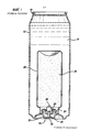
[0006] На фиг.1 изображен механизм снятия избыточного давления по патенту №6732886. Согласно фиг.1 контейнер 12, вмещающий напиток 14, имеет верхнюю часть 16, сформированную обычным способом, и может содержать отрывной язычок (не показан), известный в уровне техники. Теплообменный блок 20, имеющий клапан 18, закрепленный на опоре 22, прикреплен к верхней части 24 теплообменного блока (HEU) 20 посредством запрессовки, как известно в уровне техники. Клапан 18 содержит шток 26. При активации штока 26 клапана, сжатый газ, такой как углекислый газ, может быть направлен внутрь теплообменного блока 20 через отверстие 28 в клапане и который должен быть адсорбирован углеродистой вставкой 38, содержащей сжатый активированный угль и т.п. и может содержать связующее вещество и другие материалы. Чашка 30 расположена по штоку 26 клапана для защиты его от непреднамеренной активации. Внутри чашки 30 обеспечена перегородка 32, расположенная рядом с верхней частью штока 26 клапана. При возрастании давления внутри теплообменного блока 20 свыше заранее определенного значения опора 22 перемещается ко дну контейнера 12 и при таком перемещении шток 26 клапана входит в контакт с перегородкой 32 и вызывает активацию штока, тем самым, сбрасывая давление, возросшее внутри теплообменного блока.[0006] Figure 1 shows the mechanism for relieving excess pressure according to patent No. 6732886. 1, a
[0007] Не смотря на то, что такое устройство, показанное на фиг.1, функционирует достаточно хорошо для достижения назначенной цели, тем не менее, существует потребность в механизме сброса избыточного давления, размещенного внутри клапана и выполненного таким образом, что клапан будет нормально функционировать, но в то же время будет активирован при состоянии избыточного давления для сброса избыточного давления внутри теплообменного блока, не вызывая расширения или перемещения опоры теплообменного блока, присущих известному уровню техники.[0007] Despite the fact that such a device, shown in figure 1, is functioning well enough to achieve the intended purpose, however, there is a need for a pressure relief mechanism placed inside the valve and designed so that the valve will be normal function, but at the same time it will be activated in a state of overpressure to relieve excess pressure inside the heat exchange unit without causing expansion or displacement of the support of the heat exchange unit inherent in the prior art.
Раскрытие изобретенияDisclosure of invention
[0008] Настоящее изобретение содержит клапанный механизм для использования с контейнером, вмещающим сжатое средство, причем указанный клапанный механизм имеет полый корпус клапана с полым штоком клапана, расположенным с возможностью перемещения в указанном корпусе, и имеет приводной стержень, выходящий из первого конца корпуса и выступающий из клапана. Основание корпуса закрывает противоположный конец полого корпуса клапана. Уплотнительная пробка снятия давления расположена в полом штоке клапана. Средство для непрерывного поджатия уплотнительной пробки к основанию штока клапана для формирования между ними уплотнения для обеспечения нормально закрытого клапана, причем уплотнительная пробка подвержена воздействию содержимого контейнера для непрерывного принятия давления среды, содержавшейся в контейнере. При достижении давлением в контейнере заранее определенного значения уплотнительная пробка перемещается вверх против средства, поджимающего ее вниз, тем самым, разрывая уплотнение, установленное между уплотнительной пробкой и основанием штока, и обеспечивая возможность сброса давления, содержащегося в контейнере, путем выхода из штока клапана. Пружинящее средство расположено в указанном корпусе клапана между указанным основанием корпуса и указанным штоком клапана, уплотнением клапана, причем указанное пружинящее средство поджимает указанный шток клапана для взаимодействия с указанным уплотнением, причем указанный шток клапана подвижен между закрытым и открытым положением для ввода сжатой среды в контейнер и выпуска сжатой среды из контейнера.[0008] The present invention comprises a valve mechanism for use with a container containing compressed means, said valve mechanism having a hollow valve body with a hollow valve stem arranged to move in said body, and having a drive rod extending from the first end of the body and protruding out of the valve. The base of the body covers the opposite end of the hollow valve body. The pressure relief seal is located in the hollow valve stem. Means for continuously pressing the sealing plug against the base of the valve stem to form a seal therebetween to provide a normally closed valve, the sealing plug being exposed to the contents of the container to continuously accept the pressure of the medium contained in the container. When the pressure in the container reaches a predetermined value, the sealing plug moves up against the means pressing it down, thereby breaking the seal installed between the sealing plug and the stem base, and allowing the pressure contained in the container to be released by exiting the valve stem. Spring means are located in said valve body between said body base and said valve stem, valve seal, said spring means pressing said valve stem to interact with said seal, said valve stem being moved between a closed and an open position for introducing a compressed medium into the container and release of compressed medium from the container.
Краткое описание чертежейBrief Description of the Drawings
[0009] На фиг.1 изображен прототип.[0009] Figure 1 shows a prototype.
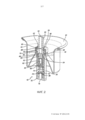
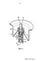
[00010] На фиг.2 изображен вид в перспективе, демонстрирующий в поперечном сечении конструкцию клапана по настоящему изобретению.[00010] Fig. 2 is a perspective view showing in cross section a valve structure of the present invention.
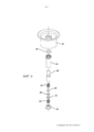
[00011] На фиг.3 изображен покомпонентный вид в перспективе, показывающей различные части клапана, представленного на фиг.2.[00011] FIG. 3 is an exploded perspective view showing various parts of the valve of FIG. 2.
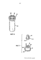
[00012] На фиг.4 изображен вид в перспективе в поперечном сечении, демонстрирующий нормальное функционирование клапана, представленного на фиг.2.[00012] FIG. 4 is a cross-sectional perspective view showing the normal functioning of the valve of FIG. 2.
[00013] На фиг.5 изображен вид в перспективе в поперечном сечении, показывающем работу клапана по сбросу давления.[00013] FIG. 5 is a cross-sectional perspective view showing a pressure relief valve.
[00014] На фиг.6 изображен вид в перспективе, демонстрирующий более подробно корпус клапана.[00014] FIG. 6 is a perspective view showing in more detail a valve body.
[00015] На фиг.7 представляет собой фигуру, подобную фиг.6, но более подробно демонстрирующую основание корпуса и пробку снятия давления.[00015] Fig. 7 is a figure similar to Fig. 6, but showing in more detail the housing base and pressure relief plug.
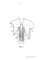
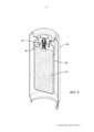
[00016] На фиг.8 изображен вид в перспективе в поперечном сечении, показывающий собранный клапан в теплообменном блоке, прикрепленный к контейнеру для напитка.[00016] FIG. 8 is a cross-sectional perspective view showing an assembled valve in a heat exchange unit attached to a beverage container.
Подробное описание чертежейDetailed Description of Drawings
[00017] На чертежах, в частности на фиг.2 и 3, изображен вид в перспективе конструкции клапана по настоящему изобретению, включая различные его части, показанные на фиг.3 в покомпонентном представлении.[00017] In the drawings, in particular in FIGS. 2 and 3, is a perspective view of a valve structure of the present invention, including various parts thereof, shown in FIG. 3 in an exploded view.
[00018] Конструкция клапана по настоящему изобретению содержит два отличных действующих клапана, помещенных в единственном теле или корпусе клапана. Первый из этих двух клапанов действует для обеспечения возможности впрыскивания среды под давлением в контейнер и последующего выпуска данной среды в атмосферу для реализации назначения конкретного контейнера. Среда может представлять собой любую без исключения парообразную фазу жидкого и газообразного газа-вытеснителя. В качестве одного примера, углекислый газ под давлением может быть введен в теплообменный блок, содержащий вставку из сжатого активированного угля, поглощающую углекислый газ. Позднее клапан может быть приведен в действие для выпуска углекислого газа в атмосферу с целью охлаждения продуктов питания или напитков, окружающих теплообменный блок. Второй из этих двух клапанов подвержен непрерывному воздействию среды под давлением, такой как углекислый газ. При превышении средой под давлением заранее определенного давления, данный клапан выводится из уплотнения избыточным давлением для обеспечения возможности сброса избыточного давления.[00018] The valve design of the present invention comprises two distinct acting valves located in a single valve body or body. The first of these two valves acts to enable the injection of pressure medium into the container and the subsequent release of this medium into the atmosphere to realize the purpose of a particular container. The medium can be any vapor phase of a liquid and gaseous propellant, without exception. As one example, pressurized carbon dioxide may be introduced into a heat exchange unit comprising a compressed activated carbon insert absorbing carbon dioxide. Later, the valve may be actuated to release carbon dioxide into the atmosphere to cool food or beverages surrounding the heat exchange unit. The second of these two valves is subject to continuous exposure to pressurized media such as carbon dioxide. If the medium under pressure exceeds a predetermined pressure, this valve is removed from the seal by overpressure to allow overpressure to be released.
[00019] Согласно представленным изображениям конструкция клапана по настоящему изобретению содержит чашку 40 клапана, в которой расположен клапан 42. Чашка 40 клапана может представлять собой глубокую вытянутую чашку, которая изображена на фиг.2-5, или, в качестве альтернативы, может представлять собой стандартную чашку клапана, показанную в прототипе на фиг.1, в которой глубокая вытяжка была бы исключена и чашка клапана проходила бы наружу к выступу 44, как изображено дополнительными пунктирными линиями 46. Клапан 42 прикреплен к опоре 48 чашки 40 клапана.[00019] According to the images shown, the valve structure of the present invention comprises a
[00020] Клапан 42 содержит полый корпус 50, нижний конец которого закрыт основанием 52 корпуса, а верхний конец содержит направленный внутрь выступ 54, в котором выполнен упор 56. Полый шток 58 клапана расположен внутри корпуса 50 клапана и содержит приводной стержень 60, проходящий вверх сквозь верхнюю часть корпуса 50 клапана и через отверстие 62 в опоре 48. В приводном стержне 60 выполнено продолговатое отверстие 64, через которое происходит взаимодействие с полой внутренней частью 66 штока 58 клапана. Шток 58 клапана содержит увеличенную верхнюю область 68, в которой выполнено заплечико 70, взаимодействующее с упором 56 на корпусе 50 клапана. Нижняя часть штока 58 клапана закрыта основанием 72 штока, в котором выполнено отверстие 74, обеспечивающее связь посредством отверстия 76 в основании корпуса с внутренним пространством контейнера или теплообменного блока. Специалисты в данной области техники поймут, что давление от сжатой среды внутри контейнера или теплообменного блока постоянно приложено посредством отверстий 76 и 74 к нижней поверхности уплотнительной пробки 80 снятия давления, размещенной внутри полой увеличенной части 68 штока 58 клапана. Пружина 82 снятия давления установлена вокруг уплотнительной пробки 80 снятия давления и упирается в верхнюю часть 84 увеличенной секции 68 штока 58 клапана. Пружина снятия давления непрерывно поджимает вниз уплотнительную пробку снятия давления, как изображено на фиг.2, для взаимодействия пробки с уплотнением 86 сброса давления, исключающим выход давления в сжатой среде, находящейся внутри контейнера или теплообменного блока, из контейнера или теплообменного блока в течение нормального функционирования клапана.[00020] The
[00021] Верхняя часть 54 корпуса 50 клапана взаимодействует с обычным клапанным уплотнением 88, таким как типичная прокладка и т.п. Клапанное уплотнение 88 закрывает отверстия 90, выполненные в приводном стержне 60.[00021] The
[00022] Нормально работающая пружина 89 удерживается между основанием 52 корпуса и основанием 72 штока и поджимает шток 58 клапана вверх, как изображено на фиг.2, так что заплечико 70 на штоке клапана взаимодействует с упором 56 на корпусе 50 клапан. В таком положении обычное клапанное уплотнение 88 закрывает отверстия 90, сформированные в приводном стержне 60. Специалисты в данной области техники поймут, что клапан, показанный на фиг.2, будет прикреплен к контейнеру или теплообменному блоку путем запрессовки выступа 44 в верхнюю часть теплообменного блока такого, как изображенного на фиг.1 и 8.[00022] A normally working
[00023] В течение нормального функционирования, при необходимости введения сжатой среды внутрь контейнера или теплообменного блока таким образом, чтобы происходило поглощение сжатыми углеродистыми частицами, содержащимися в контейнере или теплообменном блока, шток 58 клапана поджимается вниз согласно фиг.2. Такое нисходящее движение сдвигает заплечико 70 от упора 56 и перемещает отверстия 90 от уплотнения 88 для обеспечения связи между отверстием 64 в штоке 58 клапана и зазором или проходом 92 между наружной поверхностью штока 58 клапана и внутренней поверхностью корпуса 50 клапана. Сжатая среда, такая как углекислый газ, вводится через продолговатое отверстие 64 и может проходить через отверстия, например, указанные под номером 90 и расположенные в приводном стержне штока 58 клапана, и проходить через зазор или проход 92 и протекать вниз и через отверстие 76 внутрь теплообменного блока. Затем углекислый газ под давлением поглощается частицами углерода, содержащимися в теплообменном блоке и указанными под номером 124 на фиг.8. При адсорбции необходимого количества углекислого газа штоку 58 клапана обеспечивается возможность возвращения в положение, показанное на фиг.2, в момент которого отверстия 90 герметично закрыты обычным клапанным уплотнением 88, тем самым, предотвращая выпуск из теплообменного блока углекислого газа под давлением.[00023] During normal operation, when it is necessary to introduce the compressed medium inside the container or heat exchange unit so that absorption by compressed carbon particles contained in the container or heat exchange unit occurs, the
[00024] Согласно изображению, представленному на фиг.4, при необходимости активации теплообменного блока для охлаждения содержимого контейнера, окружающего теплообменный блок, нужно выпустить из теплообменного блока сжатую среду, адсорбированную частицами углерода, содержащимися в теплообменном блоке, и таким способом вытянуть тепло из материала, такого как напиток, окружающего теплообменный блок, вызывая охлаждение материала. Такое действие происходит путем отжимания штока 58 клапана вниз в противоположность силе пружины 89 согласно фиг.4. При возникновении данного действия отверстия 90 перемещаются вниз от обычного клапанного уплотнения 88. Когда происходит такое перемещение, сжатая среда, содержащаяся в теплообменном блоке, проходит через отверстие 76 в основании 52 корпуса, как показано стрелкой 94, и затем будет проходить вверх через проход 92 между наружной поверхностью штока клапана и внешней поверхностью корпуса клапана и выходить через отверстия 90 в продолговатое отверстие 64 и наружу в атмосферу через продолговатое отверстие 64 в штоке 58 клапана. Пока шток клапана поддерживается в таком нажатом состоянии, показанном на фиг.4, сжатой среде обеспечивается возможность выхода из теплообменного блока и, таким образом, отводить тепло от напитка или продуктов питания, окружающих теплообменный блок. Конструкция клапана может быть такой, что при подобном нажатии клапан блокируется в нажатом положении, тем самым, обеспечивая сжатой среде возможность выхода, как указано под номером 94, до тех пор, пока вся среда не будет рассеяна. Альтернативно, конструкция может быть такова, что шток клапана может быть нажат и впоследствии отпущен для возврата в герметичное положение, таким образом, останавливая выход сжатой среды, обеспечивая впоследствии возможность повторного нажатия штока клапана при возникновении такой необходимости. В уровне техники известно, что такое действие открытия и закрытия будет применимо при выталкивании аэрозольным газом-вытеснителем содержимого контейнера. В приведенном ниже описании будет отмечено, что уплотнительная пробка 80 снятия давления или пружина 82 сброса давления не поджимаются или не приводятся в действие каким-либо образом в течение нормального функционирования клапана, как показано на фиг.4. А именно, клапанная система снятия давления остается статичной относительно штока 58 клапана и перемещается со штоком 58 клапана в течение такого функционирования. И только пружина 89 сжимается нисходящим движением штока 58 клапана, тем самым, обеспечивая возможность выхода сжатой среды из теплообменного блока.[00024] According to the image shown in FIG. 4, if it is necessary to activate the heat exchange unit to cool the contents of the container surrounding the heat exchange unit, it is necessary to release the compressed medium adsorbed from the carbon particles contained in the heat exchange unit from the heat exchange unit, and thereby draw heat from the material such as a beverage surrounding the heat exchange unit, causing the material to cool. This action occurs by pushing the
[00025] На рассматриваемой фиг.5 изображена работа клапана по сбросу давления. Специалисты в данной области техники поймут, что нижняя поверхность 78 уплотнительной пробки 80 постоянно подвержена давлению сжатой среды. В течение работы по сбросу давления давление от сжатой среды проникает в корпус клапана через отверстие 76, выполненное в основании 52 корпуса. Эта сжатая среда также проходит через отверстие 74 в основании 72 штока. Когда давление сжатой среды превышает заранее определенное значение, которое определено жесткостью пружины 82 снятия давления, уплотнительная пробка 80 снятия давления перемещается вверх против усилия или поджатия пружины 82, как изображено на фиг.5. При этом пробка сброса давления отходит от уплотнения 86 снятия давления, тем самым обеспечивая сжатой среде возможность прохождения через отверстие 74 и вокруг внешней кромки пробки снятия давления и прохождения через продолговатое отверстие 64 в штоке 58 клапана и выхода в атмосферу. Крайняя кромка пробки снятия давления обладает размерами для обеспечения зазора между кромкой и внутренней поверхностью полого штока клапана для обеспечения пути потока для сжатой среды. При возникновении такого пути потока избыточное давление, присутствующее в теплообменном блоке, может быть распределено. Затем при понижении давления ниже заранее определенного значения пружина 82 снятия давления возвращает уплотнительную пробку 80 снятия давления во взаимодействие с уплотнением 86, которое вновь герметично закрывает теплообменный блок и предотвращает последующий выход сжатой среды из теплообменного блока в атмосферу. Спускная пробка 80 будет оставаться в герметичном положении, пока давление вновь не возрастет и не превысит заранее определенного давления. Шток 58 клапана остается статическим относительно корпуса 50 клапана в течение функционирования клапана снятия давления.[00025] Referring to FIG. 5, a pressure relief valve is shown. Specialists in the art will understand that the
[00026] Специалисты в данной области техники поймут, что система сдвоенного клапана по настоящему изобретению обеспечивает различные пути потока для сжатой среды, содержащейся в теплообменном блоке. Первый из таких путей представляет собой продолговатое отверстие 64, отверстия 90, проход 92 и отверстие 76 с поглощением сжатой среды при прохождении ее вниз или выделением сжатой среды при прохождении ее вверх. Второй из указанных путей представляет собой прохождение вверх через отверстие 76, отверстие 74, вокруг уплотнительной пробки снятия давления, через полый корпус 50 и наружу через продолговатое отверстие 64.[00026] Those skilled in the art will recognize that the dual valve system of the present invention provides various flow paths for the compressed medium contained in the heat exchange unit. The first of these paths is an
[00027] На рассматриваемой сейчас фиг.6 изображена альтернативная конструкция корпуса 50 клапана. Согласно представлению фиг.6 верхняя часть 96 корпуса клапана выполнена зубчатой, как указано под номерами 98 и 100. Такое зубчатое исполнение способствует увеличению скорости потока газа, сжатой среды, которая должна быть введена в контейнер или теплообменный блок, при заполнении контейнера. Сжатая среда проходит вокруг штока клапана, по уплотнению 88, через зубцы и в контейнер или теплообменный блок.[00027] FIG. 6 is now an alternative construction of a
[00028] На рассматриваемой сейчас фиг.7 более детально изображены основание 52 корпуса и уплотнительная пробка 80. Согласно фиг.7 основание корпуса содержит проходящий наружу выступ 102, в котором выполнено заплечико 104, взаимодействующее с нижней частью полого корпуса 50 клапана. Отверстие 76, выполненное в основании 52, выполнено направленным вверх трубчатым элементом 106, который с основанием 52 образует паз 108. Нормально работающая пружина 89 устанавливается в паз 108 и задерживается между основанием 52 корпуса и основанием 72 штока. В основании 52 корпуса выполнено заплечико 104, взаимодействующее с основанием полого корпуса 50 клапана.[00028] Fig. 7, now being considered, shows in more detail the
[00029] Уплотнительная пробка 80 снятия давления содержит направленный наружу выступ 110 и образует нижнюю поверхность 112, к которой постоянно приложено усилие сжатой среды. Согласно приведенному выше описанию и как будет понятно специалистам в данной области техники, в течение нормального функционирования контейнера, имеющего сжатую среду внутри теплообменного блока, пробка 80 снятия давления останется герметично прижатой к уплотнению снятия давления 86, а пружина 82 непрерывно удерживает пробку в герметичном положении. И лишь в случае превышения давлением сжатой среды, содержащейся в теплообменном блоке, заранее определенного уровня, уплотнительная пробка снятия давления перемещается для обеспечения возможности рассеяния избыточного давления.[00029] The
[00030] На рассматриваемой сейчас фиг.8 изображен контейнер 120, в котором расположен теплообменный блок 122. Теплообменный блок удерживается на месте за счет запрессовки выступа чашки 40 клапана по периферии отверстия теплообменного блока. Клапан 42 закреплен в чашке 40 клапана согласно приведенному выше описанию. Вставка 124 из сжатых углеродистых частиц удерживается в теплообменном блоке 122 для адсорбции и десорбции сжатого углекислого газа согласно приведенному выше описанию. Отверстие в нижней части (как изображено на фиг.8) контейнера закрыто элементом (не показан), содержащим отрывной язычок, подобный описанному и показанному на фиг.1, и напиток, как правило, содержится в контейнере 120 и окружает теплообменный блок 122.[00030] FIG. 8 is now depicted showing a
[00031] Раскрытый в настоящем описании выпускной клапан избыточного давления, размещенный в контейнере для сжатой среды, будет нормально функционировать для ввода среды в контейнер и выпуска ее из контейнера для желаемого применения, но в то же время будет автоматически приведен в действие при превышении давлением среды заранее определенного уровня для сброса избыточного давления без повреждения контейнера.[00031] The overpressure exhaust valve disclosed herein, housed in a container for compressed medium, will function normally to enter the medium into and out of the container for the desired application, but at the same time it will automatically be actuated when the pressure is exceeded a predetermined level to relieve excess pressure without damaging the container.
Claims (10)
закрывающийся контейнер, имеющий закрывающееся отверстие,
теплообменный блок, имеющий отверстие, причем теплообменный блок расположен в закрывающемся контейнере,
клапанный механизм, выполненный с возможностью обеспечения связи теплообменного блока с атмосферой,
причем клапанный механизм содержит чашку клапана, прикрепленную к закрывающемуся контейнеру и имеющую опору и выступ, и клапанный механизм прикреплен к опоре чашки клапана, и
теплообменный блок удерживается на месте за счет запрессовки выступа чашки клапана по периферии отверстия в теплообменном блоке,
при этом клапанный механизм дополнительно содержит
полый корпус,
первый клапан, расположенный в указанном корпусе и выполненный с возможностью ввода сжатой среды в контейнер и ее выпуска из контейнера, и
второй нормально закрытый клапан, расположенный в указанном корпусе и выполненный с возможностью открытия пути потока в ответ на давление сжатой среды, достигающее заранее определенного уровня, для выпуска в атмосферу для понижения избыточного давления.1. Self-cooling container containing a compressed medium containing:
a lockable container having a lockable opening,
a heat exchange unit having an opening, wherein the heat exchange unit is located in a resealable container,
a valve mechanism configured to provide communication of the heat exchange unit with the atmosphere,
moreover, the valve mechanism comprises a valve cup attached to the container and having a support and a protrusion, and the valve mechanism is attached to the valve cup support, and
the heat exchange unit is held in place by pressing in the protrusion of the valve cup around the periphery of the hole in the heat exchange unit,
wherein the valve mechanism further comprises
hollow body
the first valve located in the specified housing and configured to enter the compressed medium into the container and its release from the container, and
the second normally closed valve located in the specified housing and configured to open the flow path in response to the pressure of the compressed medium reaching a predetermined level for release into the atmosphere to reduce the overpressure.
приводной стержень, в котором выполнено продолговатое отверстие, сообщающееся с атмосферой, через которое проходит сжатая среда, и
основание штока клапана, в котором выполнено сквозное отверстие, причем второй клапан расположен в указанном полом штоке клапана.2. The container according to claim 1, in which the first valve comprises a hollow valve stem having
a drive rod in which an elongated hole is made communicating with the atmosphere through which the compressed medium passes, and
a valve stem base in which a through hole is provided, the second valve being located in said hollow valve stem.
уплотнительную пробку, установленную поверх отверстия в основании штока клапана,
вторую пружину, установленную между уплотнительной пробкой и поверхностью полой внутренней стороны штока клапана, и поджимающую указанную уплотнительную пробку к указанному отверстию в основании штока клапана для закрытия второго клапана,
причем отверстие в основании штока клапана постоянно открыто воздействию сжатой среды, находящейся в контейнере.4. The container according to claim 3, in which the second valve contains
a sealing plug installed over the hole in the base of the valve stem,
a second spring installed between the sealing plug and the surface of the hollow inner side of the valve stem, and pressing said sealing plug to the specified hole in the base of the valve stem to close the second valve,
moreover, the hole in the base of the valve stem is constantly open to the action of a compressed medium in the container.
Applications Claiming Priority (3)
| Application Number | Priority Date | Filing Date | Title |
|---|---|---|---|
| US33155610P | 2010-05-05 | 2010-05-05 | |
| US61/331,556 | 2010-05-05 | ||
| PCT/US2011/035386 WO2011140361A1 (en) | 2010-05-05 | 2011-05-05 | Over pressure release valve |
Publications (2)
| Publication Number | Publication Date |
|---|---|
| RU2012146427A RU2012146427A (en) | 2014-06-10 |
| RU2596047C2 true RU2596047C2 (en) | 2016-08-27 |
Family
ID=44904083
Family Applications (1)
| Application Number | Title | Priority Date | Filing Date |
|---|---|---|---|
| RU2012146427/12A RU2596047C2 (en) | 2010-05-05 | 2011-05-05 | Self-cooling container |
Country Status (12)
| Country | Link |
|---|---|
| US (1) | US8919618B2 (en) |
| EP (1) | EP2566782A4 (en) |
| JP (1) | JP6042804B2 (en) |
| CN (1) | CN103003171B (en) |
| AU (1) | AU2011248012B2 (en) |
| BR (1) | BR112012028024A2 (en) |
| HK (1) | HK1177613A1 (en) |
| MY (1) | MY161797A (en) |
| NZ (1) | NZ603160A (en) |
| RU (1) | RU2596047C2 (en) |
| SG (1) | SG185112A1 (en) |
| WO (1) | WO2011140361A1 (en) |
Families Citing this family (11)
| Publication number | Priority date | Publication date | Assignee | Title |
|---|---|---|---|---|
| EA201491336A1 (en) * | 2010-06-17 | 2015-03-31 | Карлсберг Брюириз А/С | COVER FOR SEALING CONTAINER COUPLING, COLLECTIVE CONTAINER, METHOD OF BOTTOMING THE DRINK FROM COLLECTIVE CONTAINER AND METHOD OF COLLECTING THE COLLECTIVE CONTAINER |
| SG2014010722A (en) * | 2011-07-11 | 2014-06-27 | Intelligent Energy Inc | Gas generator with combined gas flow valve and pressure relief vent |
| AU2014212612B2 (en) * | 2013-01-29 | 2017-11-23 | Joseph Company International, Inc. | Carbon dioxide charging apparatus and method for heat exchange unit |
| CN105377717A (en) * | 2013-03-04 | 2016-03-02 | 维佳创新有限公司 | Liquid spray dispenser system |
| US20180273369A1 (en) * | 2015-09-03 | 2018-09-27 | Joseph Company International, Inc. | Beverage filling machine for filling cans having a heat exchange unit secured internally thereof with a liquid beverage |
| CN108781370B (en) * | 2016-03-11 | 2023-06-09 | 索尼公司 | Server apparatus, information processing apparatus, and method |
| KR102122031B1 (en) * | 2018-01-16 | 2020-06-15 | 퍼스텍(주) | A Fire Extinguishing Apparatus for Aircraft Having two Engine and A Controlling Method Using Thereof |
| CN110143370A (en) * | 2019-05-07 | 2019-08-20 | 中国农业科学院农产品加工研究所 | A kind of self-heating food device |
| CN112573020A (en) * | 2020-12-24 | 2021-03-30 | 中山市美捷时包装制品有限公司 | Explosion-proof type aerial fog valve |
| MX2023012402A (en) * | 2021-04-28 | 2023-10-30 | Thermos Llc | Stopper for food jar. |
| FR3122412B1 (en) * | 2021-04-29 | 2023-10-27 | Lindal France | Sampling valve valve with overpressure protection |
Citations (4)
| Publication number | Priority date | Publication date | Assignee | Title |
|---|---|---|---|---|
| US3081919A (en) * | 1959-04-03 | 1963-03-19 | Gulf Research Development Co | Combination dispensing and excess pressure relief valve |
| US3838799A (en) * | 1972-02-09 | 1974-10-01 | Precision Valve Corp | Rapid charging valve housing |
| US5348199A (en) * | 1993-09-13 | 1994-09-20 | Summit Packaging Systems, Inc. | Aerosol valve having means to shut off flow if valve is tipped beyond a certain inclination from vertical |
| US6732889B2 (en) * | 2002-02-06 | 2004-05-11 | Ishai Oren | Pouring spout for liquid containers, and liquid containers constructed therewith |
Family Cites Families (18)
| Publication number | Priority date | Publication date | Assignee | Title |
|---|---|---|---|---|
| US3005577A (en) * | 1959-10-28 | 1961-10-24 | Otto Bernz Co Inc | Combination dispensing and excess pressure relief valve |
| BE751383R (en) * | 1969-08-12 | 1970-12-03 | Oreal | PERFECTIONED VALVE FOR PRESSURIZED CONTAINER DISPENSER OF SEVERAL PRODUCTS |
| US3666148A (en) * | 1969-10-13 | 1972-05-30 | Gillette Co | Aerosol valve with safety relief device |
| US3870203A (en) * | 1974-05-17 | 1975-03-11 | Continental Can Co | Aerosol dispensing valve |
| NZ243264A (en) * | 1991-07-02 | 1995-10-26 | Abplanalp Robert H | Aerosol valve unit for vertical or tilt action with movable valve body and valve stem being frictionally engaged and having slots and orifices facilitating moulding |
| BE1009381A3 (en) * | 1995-05-09 | 1997-03-04 | Ecopack Naamloze Vennootschap | Distributor for a product under pressure and suitable valve. |
| BR9711083A (en) * | 1996-04-04 | 1999-08-17 | Joseph Co | Self-cooling container and combined container device |
| JPH11267558A (en) * | 1998-03-20 | 1999-10-05 | Unisia Jecs Corp | Gas jetting valve |
| JP2001050497A (en) * | 1999-08-02 | 2001-02-23 | Asahi Gijutsu Kaihatsu Kk | Safety valve device for small-sized pressure container |
| US6253440B1 (en) * | 1999-01-13 | 2001-07-03 | Chill-Can International, Inc. | Method of manufacturing self cooling beverage container |
| US6105384A (en) * | 1999-01-19 | 2000-08-22 | Chill-Can International, Inc. | Self-cooling or self-heating food or beverage container having heat exchange unit with external protective coating |
| US6125649A (en) * | 1999-02-10 | 2000-10-03 | Chill-Can International, Inc. | Heat exchanger unit with conductive discs |
| BR0110239A (en) * | 2000-04-22 | 2003-06-24 | Jung Min Lee | Liquid self-cooling container |
| US6732886B2 (en) * | 2001-10-25 | 2004-05-11 | David J. Cull | Over pressure automatic release mechanism for a container housing a pressurized medium |
| US7124788B2 (en) * | 2003-07-10 | 2006-10-24 | Precision Valve Corporation | Means and method for filling bag-on-valve aerosol barrier packs |
| US20060162344A1 (en) * | 2004-03-15 | 2006-07-27 | Ontech Delaware Inc. | Container with module for heating or cooling the contents |
| FR2901255B1 (en) * | 2006-05-16 | 2010-12-10 | Lindal France | VALVE HAS TWO WAYS |
| DE102008026322A1 (en) * | 2008-05-30 | 2009-12-10 | Lindal Dispenser Gmbh | Valve for a pressurized gas container |
-
2011
- 2011-05-05 SG SG2012080461A patent/SG185112A1/en unknown
- 2011-05-05 EP EP11778362.1A patent/EP2566782A4/en not_active Withdrawn
- 2011-05-05 WO PCT/US2011/035386 patent/WO2011140361A1/en active Application Filing
- 2011-05-05 AU AU2011248012A patent/AU2011248012B2/en not_active Ceased
- 2011-05-05 CN CN201180033336.2A patent/CN103003171B/en not_active Expired - Fee Related
- 2011-05-05 NZ NZ60316011A patent/NZ603160A/en not_active IP Right Cessation
- 2011-05-05 US US13/695,281 patent/US8919618B2/en not_active Expired - Fee Related
- 2011-05-05 MY MYPI2012004744A patent/MY161797A/en unknown
- 2011-05-05 BR BR112012028024A patent/BR112012028024A2/en not_active Application Discontinuation
- 2011-05-05 RU RU2012146427/12A patent/RU2596047C2/en not_active IP Right Cessation
- 2011-05-05 JP JP2013509271A patent/JP6042804B2/en not_active Expired - Fee Related
-
2013
- 2013-05-07 HK HK13105451.6A patent/HK1177613A1/en not_active IP Right Cessation
Patent Citations (4)
| Publication number | Priority date | Publication date | Assignee | Title |
|---|---|---|---|---|
| US3081919A (en) * | 1959-04-03 | 1963-03-19 | Gulf Research Development Co | Combination dispensing and excess pressure relief valve |
| US3838799A (en) * | 1972-02-09 | 1974-10-01 | Precision Valve Corp | Rapid charging valve housing |
| US5348199A (en) * | 1993-09-13 | 1994-09-20 | Summit Packaging Systems, Inc. | Aerosol valve having means to shut off flow if valve is tipped beyond a certain inclination from vertical |
| US6732889B2 (en) * | 2002-02-06 | 2004-05-11 | Ishai Oren | Pouring spout for liquid containers, and liquid containers constructed therewith |
Also Published As
| Publication number | Publication date |
|---|---|
| CN103003171A (en) | 2013-03-27 |
| CN103003171B (en) | 2015-08-26 |
| MY161797A (en) | 2017-05-15 |
| JP2013534492A (en) | 2013-09-05 |
| AU2011248012B2 (en) | 2015-01-15 |
| WO2011140361A9 (en) | 2013-02-14 |
| US20130133761A1 (en) | 2013-05-30 |
| WO2011140361A1 (en) | 2011-11-10 |
| BR112012028024A2 (en) | 2016-09-13 |
| US8919618B2 (en) | 2014-12-30 |
| NZ603160A (en) | 2014-01-31 |
| EP2566782A1 (en) | 2013-03-13 |
| JP6042804B2 (en) | 2016-12-14 |
| SG185112A1 (en) | 2012-12-28 |
| EP2566782A4 (en) | 2014-09-24 |
| RU2012146427A (en) | 2014-06-10 |
| HK1177613A1 (en) | 2013-08-23 |
| AU2011248012A1 (en) | 2012-11-22 |
Similar Documents
| Publication | Publication Date | Title |
|---|---|---|
| RU2596047C2 (en) | Self-cooling container | |
| NL2016779B1 (en) | A capsule and a system for preparing a potable beverage from such a capsule | |
| JP7221878B2 (en) | Beverage container with pressure relief device and method of making beverage container with pressure relief device | |
| EP2419368A2 (en) | A method and a system for pressurising and dispensing fluid products stored in a bottle, can, container or similar device | |
| KR101895583B1 (en) | Aerosol can having overpressure protector and valve assembly thereof | |
| KR100978850B1 (en) | Aerosol can having overpressure protector and valve assembly thereof | |
| CN1332159C (en) | Self-refrigerating packaging and associated actuation device | |
| US11447327B2 (en) | Injection container capable of relieving overpressure and valve assembly thereof | |
| JP5339511B2 (en) | Powder cosmetic container | |
| US3519172A (en) | Fluid dispenser | |
| KR101574225B1 (en) | Cap for Receptacle for Beverage | |
| US6732886B2 (en) | Over pressure automatic release mechanism for a container housing a pressurized medium | |
| KR102112137B1 (en) | Control Valve Caps for Coffee Bean Packaging | |
| KR101186931B1 (en) | Aerosol can enable to expel high pressured gas therefrom and valve assembly thereof | |
| AU2008339098A1 (en) | A top cover for sealing an open end of a cylindrical beverage container, a container, a method for providing a top cover an a method for producing a container | |
| KR100936182B1 (en) | Nozzle assembly and can having the same | |
| JP6101050B2 (en) | Aerosol container | |
| JP3208723B2 (en) | Pressurized filling valve also serving as safety valve, safe use method and pressurized filling method | |
| KR19980701335A (en) | MULTIPURPOSE TWO-WAY SAFETY VALVE | |
| WO2011073702A1 (en) | Dispensing unit for liquid containers | |
| KR102037003B1 (en) | Aerosol can having overpressure protector and valve assembly thereof | |
| KR101897738B1 (en) | Aerosol can and valve assembly thereof | |
| KR101991708B1 (en) | Rupture pin clamp support assemblym using in the safety valve of tank for carrying oil or chemical substance | |
| KR101897739B1 (en) | Aerosol can and valve assembly thereof | |
| JP5265015B2 (en) | Gas can safety cap |
Legal Events
| Date | Code | Title | Description |
|---|---|---|---|
| MM4A | The patent is invalid due to non-payment of fees |
Effective date: 20180506 |