RU2593683C2 - Electronic device - Google Patents
Electronic device Download PDFInfo
- Publication number
- RU2593683C2 RU2593683C2 RU2014145521/28A RU2014145521A RU2593683C2 RU 2593683 C2 RU2593683 C2 RU 2593683C2 RU 2014145521/28 A RU2014145521/28 A RU 2014145521/28A RU 2014145521 A RU2014145521 A RU 2014145521A RU 2593683 C2 RU2593683 C2 RU 2593683C2
- Authority
- RU
- Russia
- Prior art keywords
- panel
- electronic device
- movable cover
- edge
- inner portion
- Prior art date
Links
Images
Classifications
-
- G—PHYSICS
- G11—INFORMATION STORAGE
- G11B—INFORMATION STORAGE BASED ON RELATIVE MOVEMENT BETWEEN RECORD CARRIER AND TRANSDUCER
- G11B17/00—Guiding record carriers not specifically of filamentary or web form, or of supports therefor
- G11B17/02—Details
- G11B17/04—Feeding or guiding single record carrier to or from transducer unit
- G11B17/0401—Details
- G11B17/0405—Closing mechanism, e.g. door
-
- G—PHYSICS
- G11—INFORMATION STORAGE
- G11B—INFORMATION STORAGE BASED ON RELATIVE MOVEMENT BETWEEN RECORD CARRIER AND TRANSDUCER
- G11B33/00—Constructional parts, details or accessories not provided for in the other groups of this subclass
- G11B33/02—Cabinets; Cases; Stands; Disposition of apparatus therein or thereon
- G11B33/022—Cases
-
- G—PHYSICS
- G11—INFORMATION STORAGE
- G11B—INFORMATION STORAGE BASED ON RELATIVE MOVEMENT BETWEEN RECORD CARRIER AND TRANSDUCER
- G11B33/00—Constructional parts, details or accessories not provided for in the other groups of this subclass
- G11B33/02—Cabinets; Cases; Stands; Disposition of apparatus therein or thereon
- G11B33/027—Covers
-
- G—PHYSICS
- G11—INFORMATION STORAGE
- G11B—INFORMATION STORAGE BASED ON RELATIVE MOVEMENT BETWEEN RECORD CARRIER AND TRANSDUCER
- G11B33/00—Constructional parts, details or accessories not provided for in the other groups of this subclass
- G11B33/14—Reducing influence of physical parameters, e.g. temperature change, moisture, dust
- G11B33/1406—Reducing the influence of the temperature
- G11B33/1413—Reducing the influence of the temperature by fluid cooling
- G11B33/142—Reducing the influence of the temperature by fluid cooling by air cooling
Abstract
Description
Область техники, к которой относится изобретениеFIELD OF THE INVENTION
Объектом изобретения является электронное устройство, в котором можно использовать оптический диск.An object of the invention is an electronic device in which an optical disc can be used.
Уровень техникиState of the art
На практике применяется электронное устройство, предназначенное для воспроизведения данных, записанных на оптическом диске, или для выполнения программы, сохраненной на оптическом диске (например, электронное устройство, описанное в документе US 7687711). В электронном устройстве согласно указанному документу предусмотрен паз для вставки оптического диска.In practice, an electronic device is used for reproducing data recorded on an optical disk or for executing a program stored on an optical disk (for example, an electronic device described in US 7687711). In the electronic device according to the specified document provides a groove for inserting an optical disk.
Раскрытие изобретенияDisclosure of invention
Необходимо, чтобы внутри электронного устройства с пазом имелся загрузочный механизм для транспортировки вставленного в паз оптического диска внутрь электронного устройства. Такой механизм, аналогичный описанному, содержит сравнительно дорогую деталь, которая увеличивает стоимость электронного устройства.It is necessary that there is a loading mechanism inside the grooved electronic device for transporting the optical disk inserted into the groove inside the electronic device. Such a mechanism, similar to that described, contains a relatively expensive part that increases the cost of an electronic device.
Согласно варианту исполнения настоящего изобретения, предлагаемое электронное устройство содержит верхнюю поверхность, изогнутую от своей передней кромки до своей задней кромки таким образом, что ее центральная часть в направлении вперед-назад может быть расположена выше передней и задней кромок. Кроме того, устройство содержит подвижную крышку, которая образует часть верхней поверхности. Подвижная крышка имеет изогнутую форму, соответствующую форме верхней поверхности, так что ее центральная часть в направлении вперед-назад может быть расположена выше передней и задней кромок. Подвижная крышка может скользить, перемещаясь из открытого положения в закрытое и наоборот. Предлагаемое устройство содержит также отделение для размещения диска, закрываемое подвижной крышкой в закрытом положении, устроенное таким образом, что диск находится внутри данного отделения. Предлагаемое устройство также содержит механизм привода диска, устанавливаемый в отделении для размещения диска и вставляемый в центральное отверстие оптического диска с целью его вращения.According to an embodiment of the present invention, the electronic device according to the invention comprises an upper surface curved from its leading edge to its trailing edge so that its central part in the front-back direction can be located above the leading and trailing edges. In addition, the device includes a movable cover, which forms part of the upper surface. The movable cover has a curved shape corresponding to the shape of the upper surface, so that its central part in the front-back direction can be located above the front and rear edges. The movable cover can slide, moving from open to closed and vice versa. The proposed device also contains a compartment for placing the disk, closed by a movable cover in the closed position, arranged so that the disk is inside this compartment. The proposed device also includes a disk drive mechanism that is installed in the compartment to accommodate the disk and inserted into the Central hole of the optical disk for rotation.
При использовании описанного выше электронного устройства, поскольку для него не требуется загрузочный механизм, возможно снижение стоимости данного устройства. Кроме того, благодаря изогнутой форме отделения для размещения диска, возможно увеличение высоты приводного вращающего устройства. В результате это обеспечивает возможность выполнения непосредственно пользователем операции вставки оптического диска.When using the electronic device described above, since it does not require a loading mechanism, the cost of this device may be reduced. In addition, due to the curved shape of the disk compartment, an increase in the height of the drive rotary device is possible. As a result, this enables the user to directly perform the insertion of the optical disc.
Краткое описание чертежейBrief Description of the Drawings
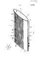
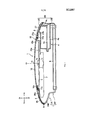
На фиг. 1 представлено перспективное изображение электронного устройства согласно настоящему изобретению в одном из возможных вариантов его исполнения. На данной фигуре подвижная крышка показана в закрытом положении.In FIG. 1 is a perspective view of an electronic device according to the present invention in one possible embodiment. In this figure, the movable cover is shown in the closed position.
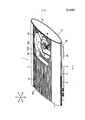
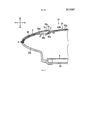
На фиг. 2 представлено перспективное изображение предлагаемого электронного устройства согласно настоящему изобретению в одном из возможных вариантов его исполнения. На данной фигуре подвижная крышка показана в открытом положении.In FIG. 2 shows a perspective image of the proposed electronic device according to the present invention in one of its possible versions. In this figure, the movable cover is shown in the open position.
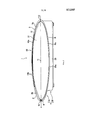
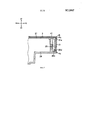
На фиг. 3 показан вид сбоку электронного устройства.In FIG. 3 shows a side view of an electronic device.
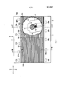
На фиг. 4 показан вид сверху электронного устройства.In FIG. 4 shows a top view of an electronic device.
На фиг. 5 представлен вид электронного устройства в разрезе по линии V-V на фиг. 4, иллюстрирующий состояние, при котором подвижная крышка находится в закрытом положении.In FIG. 5 is a sectional view of the electronic device along line V-V in FIG. 4 illustrating a state in which the movable cover is in the closed position.
На фиг.6 представлен вид электронного устройства в разрезе по линии VI-VI на фиг. 4, иллюстрирующий состояние, при котором подвижная крышка находится в закрытом положении.FIG. 6 is a sectional view of the electronic device along line VI-VI in FIG. 4 illustrating a state in which the movable cover is in the closed position.
На фиг. 7 представлен вид электронного устройства в разрезе по линии VII-VII на фиг. 4, иллюстрирующий состояние, при котором подвижная крышка находится в закрытом положении.In FIG. 7 is a sectional view of an electronic device along line VII-VII of FIG. 4 illustrating a state in which the movable cover is in the closed position.
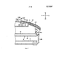
На фиг. 8 приведено перспективное изображение, показывающее рассматриваемое электронное устройство с удаленной боковой панелью с правой стороны.In FIG. 8 is a perspective view showing the electronic device in question with the side panel removed on the right side.
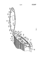
На фиг. 9 показан вид электронного устройства в разрезе по линии IX-IX на фиг. 4.In FIG. 9 is a cross-sectional view of an electronic device along line IX-IX of FIG. four.
Осуществление изобретенияThe implementation of the invention
Ниже приводится описание одного из возможных вариантов осуществления настоящего изобретения. На фиг. 1 и 2 представлены перспективные изображения электронного устройства 1 согласно настоящему изобретению в рассматриваемом варианте исполнения. Электронное устройство 1 содержит подвижную крышку 10. На фиг. 1 подвижная крышка 10 изображена в закрытом положении, а на фиг. 2 подвижная крышка 10 изображена в открытом положении. На фиг. 3 показан вид сбоку электронного устройства 1. На фиг. 4 показан вид сверху электронного устройства 1. На фиг. 4 подвижная крышка 10 показана в открытом положении. На фиг. 5 представлен вид электронного устройства в разрезе по линии V-V на фиг. 4, иллюстрирующий состояние, при котором подвижная крышка 10 находится в закрытом положении. На фиг. 6 представлен вид электронного устройства в разрезе по линии VI-VI на фиг. 4, иллюстрирующий состояние, при котором подвижная крышка 10 находится в закрытом положении. На фиг. 7 представлен вид электронного устройства в разрезе по линии VII-VII на фиг. 4, иллюстрирующий состояние, при котором подвижная крышка 10 находится в закрытом положении. В приведенном ниже описании направления X1 и Х2 на фигурах считаются направлениями влево и вправо, соответственно; направления Y1 и Y2 считаются направлениями вперед и назад, соответственно; и направления Z1 и Z2 считаются направлениями вверх и вниз, соответственно.The following is a description of one possible embodiment of the present invention. In FIG. 1 and 2 are perspective views of an electronic device 1 according to the present invention in this embodiment. The electronic device 1 comprises a
Как показано на фиг. 1, электронное устройство 1 содержит подвижную крышку 10, установленную на его верхней поверхности, верхнюю панельную секцию 22, переднюю панель 2, заднюю панель 3 и корпус 20. Как показано на фиг. 3, верхняя поверхность электронного устройства 1 имеет изогнутую форму, так что ее центральная часть в направлении вперед-назад может быть расположена выше передней кромки 1b и задней кромки 1c. Верхняя поверхность электронного устройства 1 изогнута в области от передней кромки 1b до задней кромки 1c. Иными словами, верхняя поверхность электронного устройства 1 изогнута во всей области от передней кромки 1b до задней кромки 1c. Электронное устройство 1 в рассматриваемом варианте исполнения имеет верхнюю часть в целом эллиптической формы с осевой линией С1 (см. фиг. 1) в направлении влево-вправо. Боковые поверхности верхней части 1А электронного устройства 1 имеют форму эллипса с главной осью А. В рассматриваемом варианте исполнения плоскость, в которой проходят главная ось А и осевая линия С1, расположена горизонтально. Иными словами, плоскость, в которой лежат главная ось А и осевая линия С1, проходит параллельно нижней поверхности электронного устройства 1 (точнее, нижней поверхности нижней части 1В, рассматриваемой ниже). Верхняя поверхность электронного устройства 1 представляет собой часть внешней периферической поверхности эллиптического цилиндра, расположенную выше плоскости, в которой лежат главная ось А и осевая линия С1.As shown in FIG. 1, the electronic device 1 comprises a
Электронное устройство 1 в рассматриваемом варианте исполнения имеет нижнюю часть 1В в форме коробки. Как показано на фиг. 3, передняя часть верхней части 1А выступает вперед за переднюю поверхность нижней части 1В. Кроме того, нижняя часть 1В смещена в одну сторону, вправо или влево, относительно верхней части 1А. В рассматриваемом варианте исполнения нижняя часть 1В смещена влево относительно верхней части 1А. Положение левой стороны нижней части 1В в направлении влево-вправо совпадает с положением левой стороны верхней части 1А. Кроме того, предлагаемое электронное устройство 1 может использоваться в вертикально поднятом положении, при котором левые стороны верхней части 1А и нижней части 1В расположены внизу. Правая сторона верхней части 1А выступает вправо относительно правой стороны нижней части 1В.The electronic device 1 in this embodiment has a box-shaped
В состав электронного устройства 1 входит корпус 20, предназначенный для размещения элементов и компонентов электронного устройства 1. На фиг. 5 показаны печатная плата 6 и блок питания 4 в качестве примера таких устройств и компонентов. Блок питания 4 в рассматриваемом примере содержит печатную плату 4а и корпус 4b, в котором установлена данная печатная плата 4а. В корпусе 4b предусмотрено выпускное отверстие 4c. Выпускное отверстие 4c выполнено в задней стенке корпуса 20.The electronic device 1 includes a
Корпус 20 содержит верхнюю часть 21 и нижнюю часть 29, соединенные друг с другом в вертикальном направлении. Электронное устройство 1 представляет собой развлекательное устройство, предназначенное для выполнения программы, записанной на оптическом диске D, или воспроизведения подвижных изображений или звука, сохраненных на оптическом диске D. Отделение 22а для размещения диска в виде утопленной части предусмотрено в верхней части 21 корпуса. Механизм 7 привода диска расположен в нижней области отделения 22а для размещения диска. Механизм 7 привода диска содержит приводной вращающий элемент 7а, вставляемый в центральное отверстие оптического диска D с целью его вращения. Приводной вращающий элемент 7а вращается электромотором, установленным в механизме 7 привода диска. На приводном вращающем элементе 7а предусмотрено зажимное устройство (не показано) с запорным механизмом, служащим для захвата внутренней периферийной поверхности центрального отверстия оптического диска D с целью фиксации оптического диска D на приводном вращающем элементе 7а. Кроме того, механизм 7 привода диска содержит считывающее устройство 7b, которое излучает световой луч на оптический диск D для считывания записанных на нем данных (см. фиг. 2).The
Подвижная крышка 10 может скользить, смещаясь влево-вправо между закрытым положением (фиг. 1), в котором она закрывает отделение 22а для размещения диска, и открытым положением (фиг. 2), в котором отделение 22а для размещения диска является открытым. Подвижная крышка 10 имеет изогнутую форму, соответствующую форме верхней поверхности описанного выше электронного устройства 1. Иными словами, подвижная крышка 10 изогнута таким образом, что ее центральная часть в направлении вперед-назад расположена выше передней и задней кромок. Описанная выше конфигурация подвижной крышки 10 обеспечивает расстояние между дном отделения 22а для размещения диска и подвижной крышкой 10, по сравнению с альтернативной конфигурацией подвижной крышки 10, когда она выполнена плоской. В результате это дает возможность увеличить высоту h (см. фиг. 5) приводного вращающего элемента 7а, что облегчает установку пользователем оптического диска D на приводной вращающий элемент 7а или удаление оптического диска D с приводного вращающего элемента 7а.The
Как показано на фиг. 5, приводной вращающий элемент 7а размещен под точкой Р1, которая является самой верхней точкой подвижной крышки 10. В рассматриваемом примере верхняя точка Р1 подвижной крышки 10 совпадает с верхней точкой верхней поверхности электронного устройства 1. Приводной вращающий элемент 7а расположен под верхней точкой Р1. Иными словами, ось С2 приводного вращающего элемента 7а проходит через верхнюю точку Р1. Таким образом, это облегчает увеличение высоты приводного вращающего элемента 7а. Кроме того, степень свободы конструкции зажимного устройства приводного вращающего элемента 7а может быть увеличена.As shown in FIG. 5, the driving
Вершина верхней поверхности электронного устройства 1 располагается в центральной части верхней поверхности в направлении вперед-назад. Таким образом, в рассматриваемом способе исполнения, например, приводной вращающий элемент 7а расположен в центральной области электронного устройства 1 в направлении вперед-назад. Как показано на фиг. 4, механизм 7 привода диска установлен под наклоном относительно направлений вперед и назад. В частности, продольное направление D1 механизма 7 привода диска наклонено относительно направления вперед-назад электронного устройства 1. Вышеуказанное расположение механизма 7 привода диска обеспечивает возможность уменьшения ширины электронного устройства 1 в направлении вперед-назад при размещении приводного вращающего элемента 7а в центральной части электронного устройства 1 в направлении вперед-назад.The top of the upper surface of the electronic device 1 is located in the Central part of the upper surface in the forward-backward direction. Thus, in the considered embodiment, for example, the driving
Как уже было указано выше, верхняя поверхность электронного устройства 1 образована панелью 2 (здесь называемая передней панелью), расположенной с одной стороны (в данном варианте исполнения - с передней стороны) подвижной крышки 10, и панелью 3 (далее называемой задней панелью), расположенной на противоположной стороне (в данном случае, с задней стороны) подвижной крышки 10. Подвижная крышка 10 может скользить, перемещаясь при этом между передней панелью 2 и задней панелью 3. Как показано на фиг. 3, передняя панель 2 образует переднюю часть верхней поверхности электронного устройства 1, а задняя панель 3 образует заднюю часть верхней поверхности электронного устройства 1. Панели 2 и 3 изогнуты таким образом, что верхняя поверхность электронного устройства 1 может образовывать внешнюю периферийную поверхность вышеупомянутого эллиптического цилиндра. Ширина двух панелей 2 и 3 в направлении влево-вправо равна ширине электронного устройства 1.As already mentioned above, the upper surface of the electronic device 1 is formed by a panel 2 (here called the front panel) located on one side (in this embodiment, the front side) of the
Как показано на фиг. 5, передняя часть 29b нижнего корпуса 29 выступает вперед дальше, чем нижняя часть 1В электронного устройства 1, и образует нижнюю поверхность верхней части 1А электронного устройства 1. Передняя часть нижнего корпуса 29 изогнута таким образом, что она образует переднюю часть внешней периферийной поверхности верхней части 1А эллиптической цилиндрической формы. Иными словами, передняя часть 29b нижнего корпуса 29 изогнута таким образом, что она направлена вперед и вверх. В рассматриваемом варианте исполнения две передних планки 8 и 9 размещены рядом друг с другом с левой и правой стороны между передней кромкой нижнего корпуса 29 и передней кромкой передней панели 2 (см. фиг. 1).As shown in FIG. 5, the
Как показано на фиг. 1 и 2, подвижная крышка 10 расположена между передней панелью 2 и задней панелью 3, и может скользить, перемещаясь в направлении влево-вправо между передней панелью 2 и задней панелью 3. В рассматриваемом варианте исполнения подвижная крышка 10 перемещается вручную пользователем. В частности, пользователь может толкнуть подвижную крышку 10 в сторону открытого или закрытого положения, чтобы открыть или закрыть подвижную крышку 10. В рассматриваемом варианте исполнения, при котором передняя панель 2 и задняя панель 3 расположены на передней и задней сторонах подвижной крышки 10, соответственно, когда пользователь открывает или закрывает подвижную крышку 10, предотвращается возможность толкания пользователем передней или задней частей верхней поверхности электронного устройства 1. Таким образом, изменение положения электронного устройства 1 может быть предотвращено моментом, создаваемым на электронном устройстве 1 при открытии или закрытии подвижной крышки 10. Следует отметить, что в данном варианте исполнения на самой передней части электронного устройства 1 предусмотрена кнопка для открывания подвижной крышки 10. В рассматриваемом примере функцию такой кнопки выполняет конечная часть 9а передней планки 9. Пользователь может открывать подвижную крышку 10 также с помощью данной кнопки.As shown in FIG. 1 and 2, the
В закрытом положении подвижная крышка 10 может быть расположена на левой или на правой стороне верхней поверхности электронного устройства 1. Как показано на фиг. 1, в рассматриваемом варианте исполнения подвижная крышка 10 в закрытом положении расположена на правой стороне верхней поверхности электронного устройства 1. Когда подвижная крышка 10 находится в закрытом положении, правая кромка 10 с подвижной крышки 10 расположена на правой конечной части электронного устройства 1. Таким образом, пользователь может зацепить своим пальцем правую кромку 10c подвижной крышки 10, чтобы сдвинуть подвижную крышку 10 в открытое положение. Как показано на фиг. 3, электронное устройство 1 в рассматриваемом варианте исполнения содержит боковую панель 31, которая далее будет рассмотрена более подробно. Правая кромка 10c подвижной крышки 10 расположена на верхней стороне внешней периферийной кромки боковой панели 31; она изогнута в соответствии с формой внешней периферийной кромки боковой панели 31.In the closed position, the
В открытом положении подвижная крышка 10 расположена на другой стороне верхней поверхности электронного устройства 1. Как показано на фиг. 4, в рассматриваемом варианте исполнения подвижная крышка 10 в открытом положении расположена на левой стороне верхней поверхности электронного устройства 1. Когда подвижная крышка 10 находится в открытом положении, левая кромка 10d подвижной крышки 10 расположена справа от левой конечной части электронного устройства 1. Как уже указывалось выше, электронное устройство 1 может быть использовано в вертикальном положении, при котором левая сторона верхней поверхности устройства находится внизу. Когда подвижная крышка 10 находится в открытом положении, левая кромка 10d подвижной крышки 10 расположена справа от левой конечной части электронного устройства 1. Таким образом, при использовании электронного устройства 1 в вертикальном положении, когда подвижная крышка 10 открыта, левая кромка 10d подвижной крышки 10 не ударяется об опору, на которой установлено электронное устройство 1.In the open position, the
Как показано на фиг. 1 и 2, верхняя часть 21 корпуса включает в себя верхнюю панельную секцию 22. Верхняя панельная секция 22 расположена между передней панелью 2 и задней панелью 3. Подвижная крышка 10 может перемещаться в направлении влево-вправо по верхней стороне верхней панельной секции 22. На левой или на правой стороне верхней панельной секции расположен первый боковой участок 22А, в котором сформировано вышеупомянутое отделение 22а для размещения диска (см. фиг. 2). Когда подвижная крышка 10 находится в закрытом положении, она закрывает первый боковой участок 22А. На противоположной стороне верхней панельной секции 22 находится второй боковой участок 22 В (см. фиг. 1). В рассматриваемом варианте исполнения первый боковой участок 22А верхней панельной секции 22 расположен на ее правой стороне, а второй боковой участок 22В расположен на ее левой стороне. Второй боковой участок 22В выполнен в виде пластины, которая составляет часть верхней поверхности электронного устройства 1 вместе с подвижной крышкой 10. Когда подвижная крышка 10 находится в открытом положении, она закрывает второй боковой участок 22В.As shown in FIG. 1 and 2, the
Как показано на фиг. 5, подвижная крышка 10 установлена заподлицо с передней панелью 2. В частности, передняя часть 10а подвижной крышки 10 и задняя кромка передней панели 2 располагаются в одной плоскости и прилегают друг к другу практически без зазора. Аналогичным образом, подвижная крышка 10 расположена заподлицо и с задней панелью 3. В частности, задняя часть 10b подвижной крышки 10 и передняя кромка задней панели 3 располагаются в одной плоскости и прилегают друг к другу практически без зазора.As shown in FIG. 5, the
Как показано на фиг. 6 и 7, передняя кромка 22 с верхней панельной секции 22 верхней части 21 корпуса расположена ниже задней кромки передней панели 2. Аналогично, задняя кромка 22d верхней панельной секции 22 верхней части 21 корпуса расположена ниже передней кромки задней панели 3. Таким образом, независимо от того, в каком положении находится подвижная крышка 10, в закрытом или в открытом, подвижная крышка 10 и панели 2 и 3 располагаются заподлицо друг с другом. Между передней кромкой 22 с верхней панельной секции 22 и задней кромкой передней панели 2 имеется зазор; зазор имеется также между задней кромкой 22d верхней панельной секции 22 и передней кромкой задней панели 3. Данные зазоры обеспечивают возможность вхождения передней части подвижной крышки 10 (в частности части, на которой выполнен передний направляемый участок 11а) и задней части подвижной крышки 10 (в частности части, на которой выполнен задний направляемый участок 11b).As shown in FIG. 6 and 7, the leading
Вышеупомянутый второй боковой участок 22В верхней панельной секции 22 изогнут таким образом, что верхняя поверхность электронного устройства 1 образует внешнюю периферийную поверхность вышеуказанного эллиптического цилиндра. В частности, второй боковой участок 22В изогнут в соответствии с формой подвижной крышки 10, таким образом, что его центральная часть в направлении вперед-назад располагается выше его передней и задней кромок. Такая выгнутая вверх форма второго бокового участка 22В обеспечивает увеличение внутреннего объема корпуса 20. Кроме того, поскольку второй боковой участок 22В изогнут таким образом, что его форма повторяет форму подвижной крышки 10, предотвращается возможность надавливания друг на друга передней кромки второго бокового участка 22В (а именно, передней кромки 22c верхней панельной секции 22) и задней кромки второго бокового участка 22В (а именно, задней кромки 22d верхней панельной секции 22), благодаря тому что передняя кромка второго бокового участка 22В и задняя кромка второго бокового участка 22В расположены ниже кромок панелей 2 и 3. Это обеспечивает однородную, ровную верхнюю поверхность электронного устройства 1.The aforementioned
Как показано на фиг. 6, на задней кромке передней панели 2 выполнена фаска 2а, скошенная назад и вниз. Иными словами, торцевая поверхность передней панели 2 на верхней панельной секции 22 скошена под углом назад и вниз. В результате, когда пользователь смотрит на электронное устройство 1, торцевая поверхность передней панели 2 не столь выделяется. Таким образом, становится не так заметно, что передняя кромка второго бокового участка 22В расположена ниже задней кромки передней панели 2.As shown in FIG. 6, a
Как показано на фиг. 7, на передней кромке задней панели 3 выполнена фаска 3а, скошенная вперед и вниз. Иными словами, торцевая поверхность задней панели 3 на верхней панельной секции 22 скошена под углом вперед и вниз. В результате, когда пользователь смотрит на электронное устройство 1, торцевая поверхность задней панели 3 не столь выделяется. Таким образом, становится не так заметно, что задняя кромка второго бокового участка 22В расположена ниже передней кромки задней панели 3.As shown in FIG. 7, a
Как показано на фиг. 5 и 6, в передней части верхнего корпуса 21 от верхней панельной секции 22 в направлении вперед отходит передний внутренний участок 26. Передняя панель 2 прикреплена к верхней поверхности переднего внутреннего участка 26. Передний внутренний участок 26 изогнут в соответствии с формой передней панели 2, а передняя часть электронного устройства 1 имеет двойную структуру, включающую в себя переднюю панель 2 и передний внутренний участок 26. Таким образом, обеспечивается увеличение прочности передней части электронного устройства 1 против воздействия внешнего усилия со стороны наклонной верхней стороны.As shown in FIG. 5 and 6, in front of the
Как показано на фиг. 7, в своей задней части верхний корпус 21 имеет задний внутренний участок 27, отходящий назад от верхней панельной секции 22. Задняя панель 3 прикреплена к верхней поверхности заднего внутреннего участка 27. Задний внутренний участок 27 изогнут в соответствии с формой задней панели 3, а задняя часть электронного устройства 1 имеет двойную структуру, включающую в себя заднюю панель 3 и задний внутренний участок 27. Таким образом, обеспечивается увеличение прочности задней части электронного устройства 1 против воздействия внешнего усилия со стороны наклонной верхней стороны.As shown in FIG. 7, in its rear, the
Как уже указывалось выше, передняя панель 2 и задняя панель 3 изогнуты таким образом, что верхняя поверхность электронного устройства 1 образует внешнюю периферийную поверхность вышеупомянутого эллиптического цилиндра. Кроме того, передний внутренний участок 26 и задний внутренний участок 27 изогнуты в соответствии с формой передней панели 2 и задней панели 3, соответственно. Таким образом, это предотвращает уменьшение внутреннего объема корпуса 20. Что касается формы верхней поверхности электронного устройства 1, она может быть изогнута в виде арки с вершиной в верхней точке Р1, а передняя кромка 1b верхней поверхности и задняя кромка 1с верхней поверхности также могут иметь, например, альтернативную форму, показанную пунктирной линией L3 на фиг. 3. Там, где верхняя поверхность электронного устройства 1 (в частности, передняя панель 2 и задняя панель 3) изогнута с целью образования внешней периферийной поверхности эллиптического цилиндра, передняя и задняя части верхней поверхности электронного устройства 1 выдаются наружу от пунктирной линии L3, изображающей альтернативную форму верхней поверхности (см. фиг. 3). Этим устраняется вероятность уменьшения внутреннего объема передней и задней частей корпуса 20.As already mentioned above, the
Передний внутренний участок 26 имеет часть, которая взаимодействует с передней панелью 2 с целью формирования зазора между ними. В рассматриваемом варианте исполнения передний внутренний участок 26 имеет плоский задний участок 26а, и между плоским задним участком 26а и передней панелью 2 имеется зазор, как это показано на фиг. 6. В заднем плоском участке 26а выполнено вентиляционное отверстие 26b, сообщенное с внутренней частью корпуса 20. В рассматриваемом варианте исполнения предусмотрено несколько таких вентиляционных отверстий 26b, размещенных рядом друг с другом в направлении влево-вправо в задней части 26а (см. фиг. 4). Как указано выше, между задней кромкой передней панели 2 и верхней панельной секцией 22 имеется зазор. На внутренней стороне корпуса 2 смонтирован охлаждающий вентилятор (не показан), служащий для охлаждения электронных элементов, размещенных на печатной плате 6. Когда охлаждающий вентилятор работает, он формирует поток воздуха F1, проходящий через зазор между задней кромкой передней панели 2 и верхней панельной секцией 22, и через вентиляционное отверстие 26b. В рассматриваемом варианте исполнения поток охлаждающего воздуха F1 проходит через зазор между задней кромкой передней панели 2 и через вентиляционные отверстия 26b внутрь корпуса 20. Как было указано выше, передняя панель 2 имеет скошенную фаску 2а на своей задней кромке. Данная фаска способствует сглаживанию охлаждающего потока воздуха F1. Следует отметить, что вентиляционные отверстия 26b служат также для крепления передней панели 2. В частности, на нижней поверхности передней панели 2 предусмотрены захватывающие элементы 2c, которые входят в зацепление с кромками вентиляционных отверстий 26b.The front
Задний внутренний участок 27 имеет часть, которая взаимодействует с задней панелью 3 с целью формирования зазора между ними. В рассматриваемом варианте исполнения задний внутренний участок 27 имеет плоский передний участок 27а, и между плоским передним участком 27а и задней панелью 3 имеется зазор, как это показано на фиг. 7. В переднем плоском участке 27а выполнено вентиляционное отверстие 27b, сообщенное с внутренней частью корпуса 20. В рассматриваемом варианте исполнения предусмотрено несколько таких вентиляционных отверстий 27b, размещенных рядом друг с другом в направлении влево-вправо в передней части 27а (см. фиг. 4). Как указано выше, между передней кромкой задней панели 3 и верхней панельной секцией 22 имеется зазор. Когда вышеупомянутый охлаждающий вентилятор работает, он формирует поток воздуха F2, проходящий через зазор между передней кромкой задней панели 2 и верхней панельной секцией 22, и через вентиляционное отверстие 27b. В частности, в рассматриваемом варианте исполнения поток охлаждающего воздуха F2 проходит через зазор между передней кромкой задней панели 3 и верхней панельной секцией 22, и через вентиляционные отверстия 27b внутрь корпуса 20. Как было указано выше, задняя панель 3 имеет скошенную фаску 3а на своей передней кромке. Данная фаска способствует сглаживанию охлаждающего потока воздуха F2. Следует отметить, что вентиляционные отверстия 27b служат также для крепления задней панели 3, аналогично тому, как используются вентиляционные отверстия 26b. В частности, на нижней поверхности задней панели 3 предусмотрены захватывающие элементы 3c, которые входят в зацепление с кромками вентиляционных отверстий 27b.The rear
Как было указано выше, подвижная крышка 10 может перемещаться в направлении влево-вправо по верхней стороне верхней панельной секции 22. Кроме того, подвижная крышка 10 изогнута таким образом, что ее центральная часть в направлении вперед-назад расположена выше передней и задней кромок. Таким образом, при прикреплении подвижной крышки 10 к верхней панельной секции 22 оператор может увеличить расстояние между передней и задней кромками подвижной крышки 10 путем изгибания крышки в противоположном направлении. Самый передний участок (вышеупомянутый передний направляемый участок 11a) и самый задний участок (вышеупомянутый задний направляемый участок 11b) подвижной крышки 10 изогнуты в направлении к центральной части подвижной крышки 10 в направлении вперед-назад, таким образом, что они захватывают и фиксируют переднюю и заднюю кромки верхней панельной секции 22 (см. фиг. 5). При такой конструкции подвижной крышки 10 оператор, выполняющий операцию соединения, может прикрепить подвижную крышку 10 к верхней панельной секции 22 посредством изгибания подвижной крышки 10, таким образом, чтобы увеличить расстояние между передней и задней кромками подвижной крышки 10.As indicated above, the
На верхней поверхности электронного устройства 1 сформирована передняя направляющая 22е, выполненная в направлении вдоль передней панели 2 и служащая для направления подвижной крышки 10. В рассматриваемом варианте исполнения передняя направляющая 22е выполнена на передней кромке верхней панельной секции 22, как показано на фиг. 6, и служит в качестве направляющей для подвижной крышки 10 при ее перемещении влево-вправо. Кроме того, на верхней поверхности электронного устройства 1 сформирована задняя направляющая 22f, выполненная в направлении вдоль задней панели 3 и служащая для направления подвижной крышки 10. В рассматриваемом варианте исполнения задняя направляющая 22f выполнена на задней кромке верхней панельной секции 22, как показано на фиг. 7, и служит в качестве направляющей для подвижной крышки 10 при ее перемещении влево-вправо. На своей передней кромке подвижная крышка 10 имеет передний направляемый участок 11а, входящий в зацепление с передней направляющей 22е, как показано на фиг. 5. На своей задней кромке подвижная крышка 10 имеет задний направляемый участок 11b, входящий в зацепление с задней направляющей 22f. Передний направляемый участок 11a и задний направляемый участок 11b выступают к центральной части подвижной крышки 10 в направлении вперед-назад. Передняя направляющая 22е верхней панельной секции 22 представляет собой канавку, в которую входит передний направляемый участок 11а, а задняя направляющая 22f представляет собой канавку, в которую вставлен задний направляемый участок 11b. Подвижная крышка 10 удерживается на верхней панельной секции 22 с помощью своего переднего направляемого участка 11а и заднего направляемого участка 11b.On the upper surface of the electronic device 1, a
Как показано на фиг. 6, между задней кромкой передней панели 2 и передней кромкой 22c верхней панельной секции 22 имеется зазор. Передняя часть подвижной крышки 10 заходит под заднюю часть передней панели 2 по данному зазору (см. фиг. 5). Иными словами, передняя панель 2 закрывает переднюю часть подвижной крышки 10. Вышеупомянутый направляемый участок 11a подвижной крышки 10 расположен на части крышки, находящейся под передней панелью 2. Соответственно, направляющий механизм подвижной крышки 10 (а именно, вышеуказанные направляемый участок 11a и направляющая 22c) защищены передней панелью 2, чем обеспечивается плавное скользящее движение подвижной крышки 10. Кроме того, предотвращается раскрытие направляющего механизма. В частности, в рассматриваемом примере передняя панель 2 имеет скошенную фаску 2a на своей задней кромке. Таким образом, если обеспечивается зазор между передней панелью 2 и передней кромкой 22c верхней панельной секции 22, область взаимного перекрытия передней панели и подвижной крышки 10 (то есть диапазон, в котором подвижная крышка 10 защищена передней панелью 2) может быть увеличена.As shown in FIG. 6, there is a gap between the trailing edge of the
Как показано на фиг. 7, между передней кромкой задней панели 3 и задней кромкой 22d верхней панельной секции 22 имеется зазор. Задняя часть подвижной крышки 10 заходит под переднюю часть задней панели 3 через данный зазор (см. фиг. 5). Иными словами, задняя панель 3 закрывает заднюю часть подвижной крышки 10. Вышеупомянутый направляемый участок 11b подвижной крышки 10 расположен на части крышки, находящейся под задней панелью 3. Соответственно, направляющий механизм подвижной крышки 10 (а именно, вышеуказанные направляемый участок 11b и направляющая 22f) защищены задней панелью 2, чем обеспечивается плавное скользящее движение подвижной крышки 10. Кроме того, предотвращается раскрытие направляющего механизма. В частности, в рассматриваемом примере задняя панель 3 имеет скошенную фаску 3а на своей передней кромке. Таким образом, если обеспечивается зазор между задней панелью 3 и задней кромкой 22d верхней панельной секции 22, область, взаимного перекрытия задней панели и подвижной крышки 10 (то есть диапазон, в котором подвижная крышка 10 защищена задней панелью 2) может быть увеличена.As shown in FIG. 7, there is a gap between the leading edge of the
Как показано на фиг. 1 и 3, на подвижной крышке 10 выполнено множество канавок 10e. Таким образом, это повышает прочность подвижной крышки 10 и ее сопротивляемость воздействию внешнего усилия, прилагаемого к подвижной крышке 10 при ее сдвигании. В настоящем варианте исполнения канавки 10e ориентированы в направлении влево-вправо и расположены на одинаковых расстояниях друг от друга в направлении вперед-назад. В частности, в рассматриваемом примере канавки 10e выполнены на верхней поверхности подвижной крышки 10 в области от передней кромки до задней кромки подвижной крышки 10.As shown in FIG. 1 and 3, a plurality of
Как указывалось выше, верхняя панельная секция 22 имеет второй боковой участок 22В. Как показано на фиг. 1, множество канавок 22g выполнено также на втором боковом участке 22В. За счет этого может быть достигнуто повышение прочности верхней поверхности электронного устройства 1. В рассматриваемом варианте исполнения канавки 22g также ориентированы в направлении влево-вправо, аналогично канавкам 10e подвижной крышки 10, и выполнены на верхней поверхности второго бокового участка 22В. В результате при сдвигании подвижной крышки 10 в направлении влево-вправо нижняя поверхность подвижной крышки 10 контактирует с участками между расположенными рядом двумя соседними канавками 22g. Таким образом, даже при образовании следа от перемещений подвижной крышки 10 на верхней поверхности второго бокового участка 22В, этот след не будет выделяться. В рассматриваемом варианте исполнения канавки 22g выполнены в области от передней кромки до задней кромки второго бокового участка 22В. В результате независимо от того, на какую часть верхней поверхности подвижной крышки 10 будет нажимать пользователь при смещении подвижной крышки 10, след от ее сдвигания на верхней поверхности второго бокового участка не будет выделяться. Следует отметить, что в данном варианте исполнения множество канавок 22h, проходящих в направлении влево-вправо, выполнено также и на первом боковом участке 22А, как показано на фиг. 4.As indicated above, the
Как было указано выше, электронное устройство 1 содержит боковую панель 31, с помощью которой образованы левая и правая стороны электронного устройства 1 (см. фиг. 3). На фиг. 8 приведено перспективное изображение, показывающее рассматриваемое электронное устройство с удаленной боковой панелью 31 с правой стороны. На фиг. 9 показан вид электронного устройства в разрезе по линии IX-IX на фиг. 4.As indicated above, the electronic device 1 comprises a
Как показано на фиг. 8 и 9, корпус 20 содержит внутреннюю боковую панель 25. В рассматриваемом варианте исполнения внутренняя боковая панель 25 сформирована на верхнем корпусе 21. Внутренняя боковая панель 25 образует верхнюю часть 1А электронного устройства 1, которая имеет фактически эллиптическую форму при виде сбоку. Боковая панель 31 прикреплена к внутренней боковой панели 25, и боковая часть электронного устройства 1 имеет двойную конструкцию, состоящую из внутренней боковой панели 25 и внешней боковой панели 31. Таким образом, это может обеспечить повышение прочности корпуса 20. Кроме того, в рассматриваемом варианте исполнения отверстие, в которое вставляется накопитель на жестком диске 13, выполнено в показанной на фиг. 8 внутренней боковой панели 25 на правой стороне верхнего корпуса 21, и боковая панель 31 служит также для закрывания накопителя на жестком диске 13. Следует отметить, что в электронном устройстве 1 согласно рассматриваемому варианту исполнения верхний корпус 21 и нижний корпус 29 прикреплены друг к другу винтом 41, как показано на фиг. 9.As shown in FIG. 8 and 9, the
Как показано на фиг. 8, в верхней части 1А электронного устройства 1 с правой стороны имеется фланец R, проходящий по периферии боковой панели 31. В данном варианте исполнения фланец R образован правой кромкой 2b передней панели 2, правой кромкой 10с подвижной крышки 10, правой кромкой 3b задней панели 3 и правой кромкой 29а нижнего корпуса 29, которые окружают внешнюю периферийную кромку боковой панели 31 (см. фиг. 3). Боковая панель 31 образует верхнюю часть 1А электронного устройства 1 и имеет эллиптическую форму. Фланец R имеет эллиптическую кольцевую форму. Фланец R имеет скошенную фаску Ra. Скошенная фаска Ra выполнена с наклоном, таким образом, что она направлена внутрь от фланца R (в направлении к осевой линии С1) и наружу от электронного устройства в направлениях влево и вправо. Далее, скошенная фаска Ra выполнена по всей периферии фланца R. Как показано на фиг. 9, между фланцем R и внешней периферийной кромкой боковой панели 31 имеется зазор. Иными словами, размер боковой панели 31 немного меньше размера фланца R. Скошенная фаска Ra ориентирована таким образом, что она закрывает внешнюю периферийную кромку боковой панели 31 при виде сбоку. Таким образом, даже при смещении боковой панели 31 и ее отходе от фланца R, через образовавшийся зазор невозможно будет увидеть внутреннюю боковую панель 25. Таким образом, предотвращается возможное выделение подобных образующихся зазоров.As shown in FIG. 8, in the
Как показано на фиг. 9, в корпусе 20 предусмотрено вентиляционное отверстие 29c. Вентиляционное отверстие 29c выполнено в таком месте, что оно скрывается внешней периферийной частью боковой панели 31. Таким образом, несмотря на предотвращение возможного ухудшения внешнего вида электронного устройства 1 вследствие наличия вентиляционного отверстия 29c, тем не менее, обеспечивается образование охлаждающего воздушного потока F3, который проходит по зазору между фланцем R и внешней периферийной кромкой боковой панели 31 и через вентиляционное отверстие 29c. В рассматриваемом варианте исполнения воздушный поток F3, образующийся в результате работы вышеупомянутого охлаждающего вентилятора, проходит по зазору между фланцем R и внешней периферийной кромкой боковой панели 31 и через вентиляционное отверстие 29c наружу корпуса 20.As shown in FIG. 9, a
В рассматриваемом варианте исполнения на верхней поверхности нижнего корпуса 29 выполнено ребро 29d, как показано на фиг. 9. Ребро 29 в данном варианте исполнения проходит от передней кромки до задней кромки нижнего корпуса 29 (см. фиг. 8). В данном ребре 29 выполнено множество вентиляционных отверстий 29c, размещенных рядом друг с другом. Следует отметить, что ребро 29 в рассматриваемом примере расположено внутри (ближе к центру устройства) относительно внутренней боковой панели 25 верхнего корпуса 21.In this embodiment, a
Как показано на фиг. 8, на внешней периферийной кромке боковой панели 31 выполнена скошенная фаска 31а. Как показано на фиг. 9, скошенная фаска 31а расположена напротив скошенной фаски Ra фланца R. В частности, скошенная фаска 31a расположена таким образом, что она направлена к корпусу 20 и наружу от внешней периферийной кромки боковой панели 31. Между скошенной фаской 31а боковой панели 31 и скошенной фаской Ra фланца R проходит поток охлаждающего воздуха по практически прямолинейной траектории к вентиляционному отверстию 29c. Таким образом, данная фаска способствует выравниванию охлаждающего потока воздуха F3.As shown in FIG. 8, a
Следует отметить, что, несмотря на то, что в данном случае описывается правая часть электронного устройства 1, изображенная на фиг. 8 и 9, внутренняя боковая панель 25 верхнего корпуса 21 и вентиляционное отверстие 29 с нижнего корпуса 29 выполнены также и на левой стороне электронного устройства 1.It should be noted that, although the right-hand side of the electronic device 1 shown in FIG. 8 and 9, the
Как показано на фиг. 8, на боковой панели 31 имеется множество (в рассматриваемом варианте исполнения - семь) элементов крепления 31d, расположенных на внутренней поверхности панели напротив внутренней боковой панели 25. С другой стороны, на внутренней боковой панели 25 предусмотрены охватывающие элементы крепления 25a, в которые вставляются элементы крепления 31d. В рассматриваемом варианте исполнения конечные части вставных элементов крепления 31d отогнуты в одном и том же направлении (в рассматриваемом варианте исполнения - в направлении вперед). Таким образом, при креплении боковой панели 31, боковую панель 31 располагают параллельно внутренней боковой панели 25, а затем перемещают вперед; при этом вставные элементы крепления 31d боковой панели 31 входят в зацепление с охватывающими элементами крепления 25a внутренней боковой панели 25. Далее, на боковой панели 31 имеется выступ 31e. Кроме того, на внутренней боковой панели 25 предусмотрено ребро 25b. Во время прикрепления боковой панели 31, при перемещении боковой панели 31 вперед, выступ 31e продвигается вперед за ребро 25b. Это обеспечивает невозможность случайного удаления боковой панели 31 без намерения пользователя. Следует отметить, что для того, чтобы упростить перемещение выступа 31e за ребро 25b, на выступе 31e имеется скошенная фаска (на внешней стороне выступа, т.е. на стороне, входящей в контакт с ребром 25b).As shown in FIG. 8, on the
Как уже было указано выше, подвижная крышка 10 изогнута таким образом, что ее центральная часть в направлении вперед-назад расположена выше передней и задней кромок. Отделение 22a для размещения диска, в которое вставляют оптический диск, закрывается подвижной крышкой 10 при ее установке в закрытое положение. В отделении 22a для размещения диска расположен приводной вращающий элемент 7a, вставляемый в центральное отверстие оптического диска D для его вращения. В рассматриваемой конфигурации, поскольку для описанного выше электронного устройства не требуется механизм загрузки диска, возможно снижение стоимости устройства. Кроме того, благодаря возможности увеличения высоты приводного вращающего элемента 7a возможно упрощение операции установки оптического диска в отделение 22a для размещения диска.As already mentioned above, the
Помимо этого, подвижная крышка 10 может перемещаться между панелью 2 с одной стороны (в рассматриваемом примере - спереди) подвижной крышки 10 и панелью 3 с противоположной стороны (в рассматриваемом примере - сзади) подвижной крышки 10. Далее, на верхней поверхности электронного устройства 1 вдоль передней панели 2 выполнена направляющая 22e для направления подвижной крышки 10, а вдоль задней панели 3 выполнена направляющая 22f, также служащая для направления подвижной крышки 10. В рассматриваемом варианте исполнения, когда пользователь смотрит на электронное устройство 1, направляющие 22e и 22f скрыты и не видны.In addition, the
Кроме того, электронное устройство 1 содержит переднюю панель 2, являющуюся передней частью верхней поверхности устройства, и заднюю панель 3, которая является задней частью верхней поверхности электронного устройства, а подвижная крышка 10 может перемещаться посредством сдвигания влево и вправо между передней панелью 2 и задней панелью 3. Рассматриваемый вариант исполнения электронного устройства обеспечивает неизменность положения электронного устройства при сдвигании подвижной крышки 10.In addition, the electronic device 1 includes a
Передняя панель 2 и подвижная крышка 10 расположены заподлицо друг с другом, а на задней кромке передней панели 2 выполнена скошенная фаска 2a, ориентированная под наклоном в направлении назад и вниз. В рассматриваемом варианте исполнения зазор между задней кромкой передней панели 2 и верхним корпусом 21 является незаметным.The
Передняя панель 3 и подвижная крышка 10 расположены заподлицо друг с другом, а на передней кромке задней панели 3 выполнена скошенная фаска 3а, ориентированная под наклоном в направлении вперед и вниз. В рассматриваемом варианте исполнения зазор между передней кромкой задней панели 3 и верхним корпусом 21 является незаметным.The
Верхняя поверхность электронного устройства 1 имеет изогнутую форму, так что ее центральная часть в направлении вперед-назад расположена выше передней кромки 1b и задней кромки 1c. Кроме того, электронное устройство 1 содержит переднюю панель, расположенную перед подвижной крышкой 10 и представляющую собой часть изогнутой верхней поверхности электронного устройства 1 совместно с подвижной крышкой 10, и корпус 20, содержащий передний внутренний участок 26, к верхней поверхности которого прикреплена передняя панель 2. Кроме того, передний внутренний участок 26 является изогнутым в соответствии с формой передней панели 2. В рассматриваемой конфигурации передняя часть электронного устройства 1 имеет двойную конструкцию, что обеспечивает возможности повышения прочности передней части.The upper surface of the electronic device 1 has a curved shape, so that its central part in the front-back direction is located above the
Корпус 20 содержит верхнюю панельную секцию 22, на верхней стороне которой расположена подвижная крышка 10. От верхней панельной секции 22 вперед отходит передний внутренний участок 26. Между передней кромкой верхней панельной секции 22 и задней кромкой передней панели 2 имеется зазор, а передний внутренний участок 26 включает в себя часть (заднюю часть 26а), которая образует зазор с передней панелью 2. В задней части 26а переднего внутреннего участка 26 выполнены вентиляционные отверстия 26b, соединяющиеся с внутренней областью корпуса 20. При такой конфигурации, поскольку вентиляционные отверстия 26b закрыты передней панелью 2 и внешний вид электронного устройства 1 не ухудшается наличием вентиляционных отверстий 26b, зазор между передней кромкой верхней панельной секции 22 и задней кромкой передней панели 2 может выполнять функцию канала для прохождения потока охлаждающего воздуха.The
Электронное устройство 1 содержит корпус 20 с задним внутренним участком 27, к верхней поверхности которого крепится задняя панель 3. Задний внутренний участок 27 является изогнутым в соответствии с формой задней панели 3. В рассматриваемой конфигурации задняя часть электронного устройства 1 имеет двойную конструкцию, что обеспечивает возможности повышения прочности задней части.The electronic device 1 includes a
Корпус 20 содержит верхнюю панельную секцию 22, на верхней стороне которой расположена подвижная крышка 10, и от верхней панельной секции 22 назад отходит задний внутренний участок 27. Между задней кромкой верхней панельной секции 22 и передней кромкой задней панели 3 имеется зазор, а задний внутренний участок 27 включает в себя часть (переднюю часть 27a), которая образует зазор с задней панелью 3. В передней части 27a заднего внутреннего участка 27 выполнены вентиляционные отверстия 27b, соединяющиеся с внутренней областью корпуса 20. В рассмотренном варианте исполнения внешний вид электронного устройства 1 не ухудшается в результате наличия вентиляционных отверстий 27b.The
Предусмотрена верхняя панельная секция 22, расположенная между передней панелью 2 и задней панелью 3. Верхняя панельная секция 22 имеет второй боковой участок 22В в форме пластины, которая закрывается подвижной крышкой 10, когда подвижная крышка 10 находится в открытом положении, и изогнута в соответствии с формой подвижной крышки 10. На верхней поверхности второго бокового участка 22В выполнено множество канавок 22g, проходящих в направлении влево-вправо. При такой конструкции, даже при образовании следа от перемещений подвижной крышки 10 на верхней поверхности второго бокового участка 22В, этот след не будет заметен.An
Следует отметить, что настоящее изобретение не ограничивается вышеописанным вариантом исполнения электронного устройства 1 и может быть различными способами модифицировано.It should be noted that the present invention is not limited to the above-described embodiment of the electronic device 1 and can be modified in various ways.
Например, канавки 10e на подвижной крышке 10 и канавки 22g на верхней панельной секции 22 не являются обязательными.For example, the
Кроме того, боковую панель 31 устанавливать также не обязательно. В таком случае элемент, образующий боковую поверхность электронного устройства 1, может быть выполнен на верхнем корпусе 21 или на нижнем корпусе 29.In addition, the
В электронном устройстве 1 направляемые элементы 11a и 11b подвижной крышки 10 выполнены так, чтобы входить в зацепление с передней кромкой и задней кромкой, соответственно, верхней панельной секции 22. Однако конструкция крепления подвижной крышки 10 вовсе не ограничивается данным вариантом. Например, направляемые элементы 11a и 11b подвижной крышки 10 могут выступать вперед и назад, соответственно. Далее, направляемые элементы 11a и 11b могут входить в зацепление с передней панелью 2 и задней панелью 3 соответственно, чтобы обеспечивать крепление подвижной крышки 10 к электронному устройству 1.In the electronic device 1, the guided
Кроме того, верхняя поверхность электронного устройства 1 может быть выполнена изогнутой, но образующей не внешнюю периферийную поверхность эллиптического цилиндра, а образующей внешнюю периферийную поверхность обыкновенного цилиндра.In addition, the upper surface of the electronic device 1 can be made curved, but forming not the outer peripheral surface of the elliptical cylinder, but forming the outer peripheral surface of an ordinary cylinder.
Перемещение подвижной крышки 10 может производиться в положение дальше конечного положения рассмотренного варианта (т.е. дальше левого крайнего положения) электронного устройства 1.The movement of the
Помимо этого, наличие как передней панели 2, так и задней панели 3 не является обязательным. В таком случае верхний корпус 21 в передней части (на переднем внутреннем участке 27) или в задней части (на заднем внутреннем участке 27) может представлять собой верхнюю поверхность электронного устройства 1.In addition, the presence of both the
Кроме того, передние планки 8 и 9, размещенные в передней части электронного устройства 1, также не являются обязательными.In addition, the
Claims (10)
верхнюю поверхность, изогнутую от своей передней кромки до своей задней кромки таким образом, что центральная часть верхней поверхности в направлении вперед-назад расположена выше передней и задней кромок;
подвижную крышку, образующую частью верхней поверхности и изогнутую в соответствии с формой верхней поверхности таким образом, что центральная часть крышки в направлении вперед-назад расположена выше передней и задней кромок крышки, причем подвижная крышка имеет возможность перемещения путем скольжения между открытым и закрытым положениями;
отделение для размещения диска, закрываемое подвижной крышкой в закрытом положении и выполненное таким образом, что диск находится внутри данного отделения; и
приводной вращающий элемент, расположенный в отделении для размещения диска и вставляемый в центральное отверстие оптического диска с целью его вращения.1. An electronic device containing:
an upper surface curved from its leading edge to its trailing edge so that the central portion of the upper surface in the forward and backward direction is located above the leading and trailing edges;
a movable lid forming a part of the upper surface and curved in accordance with the shape of the upper surface so that the central part of the lid in the front-back direction is located above the front and rear edges of the lid, and the movable lid can be moved by sliding between the open and closed positions;
a compartment for accommodating the disc, closed by a movable cover in the closed position and made so that the disc is inside the compartment; and
a drive rotary element located in the disk compartment and inserted into the center hole of the optical disk for rotation.
переднюю панель, образующую переднюю часть верхней поверхности электронного устройства; и
заднюю панель, образующую заднюю часть верхней поверхности электронного устройства;
при этом подвижная крышка имеет возможность перемещения путем скольжения в направлении влево и вправо между передней панелью и задней панелью.3. The electronic device according to claim 1, which further comprises:
the front panel forming the front of the upper surface of the electronic device; and
a rear panel forming the rear of the upper surface of the electronic device;
while the movable cover has the ability to move by sliding in the left and right directions between the front panel and the rear panel.
переднюю панель, расположенную перед подвижной крышкой и образующую изогнутую верхнюю поверхность электронного устройства вместе с подвижной крышкой; и
корпус с передним внутренним участком, к верхней поверхности которого прикреплена передняя панель; причем передний внутренний участок изогнут в соответствии с формой передней панели.6. The electronic device according to claim 1, which further comprises:
a front panel located in front of the movable cover and forming a curved upper surface of the electronic device together with the movable cover; and
a housing with a front inner portion, to the upper surface of which a front panel is attached; moreover, the front inner portion is curved in accordance with the shape of the front panel.
причем передний внутренний участок отходит вперед от верхней панельной секции,
при этом между передней кромкой верхней панельной секции и задней кромкой передней панели имеется зазор,
при этом передний внутренний участок содержит часть, расположенную с зазором от передней панели, и
в части переднего внутреннего участка выполнено вентиляционное отверстие, соединенное с внутренней частью корпуса.7. The electronic device according to claim 6, in which the housing contains an upper panel section, on the upper side of which is a movable cover,
wherein the front inner portion extends forward from the upper panel section,
there is a gap between the leading edge of the upper panel section and the trailing edge of the front panel,
wherein the front inner portion comprises a portion located with a gap from the front panel, and
in the front inner portion, a ventilation hole is made, connected to the inner part of the housing.
заднюю панель, расположенную сзади подвижной крышки и образующую изогнутую верхнюю поверхность электронного устройства вместе с подвижной крышкой; и
корпус с задним внутренним участком, к верхней поверхности которого прикреплена задняя панель;
причем задний внутренний участок изогнут в соответствии с формой задней панели.8. The electronic device according to claim 1, which further comprises:
a rear panel located behind the movable cover and forming a curved upper surface of the electronic device along with the movable cover; and
a housing with a rear inner portion, to the upper surface of which a rear panel is attached;
moreover, the rear inner portion is curved in accordance with the shape of the rear panel.
причем задний внутренний участок отходит назад от верхней панельной секции,
при этом между задней кромкой верхней панельной секции и передней кромкой задней панели имеется зазор,
при этом задний внутренний участок содержит часть, расположенную с зазором от задней панели, и
в части заднего внутреннего участка выполнено вентиляционное отверстие, соединенное с внутренней частью корпуса.9. The electronic device according to claim 8, in which the housing further comprises an upper panel section, on the upper side of which is located a movable cover,
and the rear inner portion extends back from the upper panel section,
there is a gap between the rear edge of the upper panel section and the front edge of the rear panel,
wherein the rear inner portion comprises a portion located with a gap from the rear panel, and
in the rear inner portion, a ventilation hole is made, connected to the inner part of the housing.
при этом электронное устройство дополнительно содержит верхнюю панельную секцию, расположенную между передней панелью и задней панелью,
верхняя панельная секция имеет боковой участок в форме пластины, которая закрыта подвижной крышкой, когда подвижная крышка находится в открытом положении, и изогнута в соответствии с формой подвижной крышки,
причем на верхней поверхности бокового участка выполнено множество канавок, проходящих в направлении влево-вправо. 10. The electronic device according to claim 3, in which the movable cover has the ability to move by sliding left or right,
wherein the electronic device further comprises an upper panel section located between the front panel and the rear panel,
the upper panel section has a side portion in the form of a plate, which is closed by the movable cover when the movable cover is in the open position, and is curved in accordance with the shape of the movable cover,
moreover, on the upper surface of the lateral section there are many grooves extending in the left-right direction.
Applications Claiming Priority (3)
| Application Number | Priority Date | Filing Date | Title |
|---|---|---|---|
| JP2012-092502 | 2012-04-13 | ||
| JP2012092502 | 2012-04-13 | ||
| PCT/JP2013/060445 WO2013154041A1 (en) | 2012-04-13 | 2013-04-05 | Electronic device |
Publications (2)
| Publication Number | Publication Date |
|---|---|
| RU2014145521A RU2014145521A (en) | 2016-06-10 |
| RU2593683C2 true RU2593683C2 (en) | 2016-08-10 |
Family
ID=49327609
Family Applications (1)
| Application Number | Title | Priority Date | Filing Date |
|---|---|---|---|
| RU2014145521/28A RU2593683C2 (en) | 2012-04-13 | 2013-04-05 | Electronic device |
Country Status (7)
| Country | Link |
|---|---|
| US (1) | US9105296B2 (en) |
| EP (1) | EP2838088B1 (en) |
| JP (1) | JP5818976B2 (en) |
| CN (1) | CN104205223B (en) |
| IN (1) | IN2014KN02293A (en) |
| RU (1) | RU2593683C2 (en) |
| WO (1) | WO2013154041A1 (en) |
Families Citing this family (3)
| Publication number | Priority date | Publication date | Assignee | Title |
|---|---|---|---|---|
| JP1586534S (en) * | 2016-09-23 | 2017-09-25 | ||
| CN113542476B (en) * | 2020-04-16 | 2023-09-08 | 深圳富泰宏精密工业有限公司 | Back cover ejection mechanism and electronic device |
| CN115316049A (en) | 2020-05-15 | 2022-11-08 | 索尼互动娱乐股份有限公司 | Support for electronic equipment and electronic equipment assembly |
Citations (2)
| Publication number | Priority date | Publication date | Assignee | Title |
|---|---|---|---|---|
| JPH087428A (en) * | 1994-06-27 | 1996-01-12 | Matsushita Electric Ind Co Ltd | Disk reproducing device |
| US7687711B2 (en) * | 2005-05-15 | 2010-03-30 | Sony Computer Entertainment Inc. | Electronic device |
Family Cites Families (12)
| Publication number | Priority date | Publication date | Assignee | Title |
|---|---|---|---|---|
| JP2000123561A (en) * | 1998-10-09 | 2000-04-28 | Sony Corp | Recording and/or reproducing device |
| DE20006442U1 (en) * | 2000-04-07 | 2000-08-24 | Enlight Corp | Push button on the front panel of a computer |
| US20040047617A1 (en) * | 2002-08-21 | 2004-03-11 | Matos Jose R. | Disc player system |
| TW568323U (en) * | 2002-09-27 | 2003-12-21 | Lite On It Corp | Cap opening and closing device for cap-lifting CD-ROM drive |
| JP4306228B2 (en) * | 2002-11-13 | 2009-07-29 | ソニー株式会社 | Recording medium cartridge |
| JP4196277B2 (en) | 2003-09-01 | 2008-12-17 | ソニー株式会社 | Electronics |
| JP2006134404A (en) * | 2004-11-04 | 2006-05-25 | Sanyo Electric Co Ltd | Player door opening and closing device |
| US7398535B2 (en) * | 2004-12-10 | 2008-07-08 | Coby Electronics Corporation | Portable media player |
| JP2007095174A (en) | 2005-09-29 | 2007-04-12 | Hitachi Ltd | Information reproducing device |
| CN101587738A (en) * | 2008-05-23 | 2009-11-25 | 鸿富锦精密工业(深圳)有限公司 | CD player |
| CN201820451U (en) * | 2009-09-10 | 2011-05-04 | 珠海市雅力实业有限公司 | Portable sliding closure visual optical disk player |
| CN201491429U (en) * | 2009-09-10 | 2010-05-26 | 珠海市雅力实业有限公司 | Sliding cover mechanism for portable multimedia device |
-
2013
- 2013-04-05 US US14/391,699 patent/US9105296B2/en active Active
- 2013-04-05 JP JP2014510146A patent/JP5818976B2/en active Active
- 2013-04-05 IN IN2293KON2014 patent/IN2014KN02293A/en unknown
- 2013-04-05 RU RU2014145521/28A patent/RU2593683C2/en active
- 2013-04-05 CN CN201380017420.4A patent/CN104205223B/en active Active
- 2013-04-05 WO PCT/JP2013/060445 patent/WO2013154041A1/en active Application Filing
- 2013-04-05 EP EP13775852.0A patent/EP2838088B1/en active Active
Patent Citations (2)
| Publication number | Priority date | Publication date | Assignee | Title |
|---|---|---|---|---|
| JPH087428A (en) * | 1994-06-27 | 1996-01-12 | Matsushita Electric Ind Co Ltd | Disk reproducing device |
| US7687711B2 (en) * | 2005-05-15 | 2010-03-30 | Sony Computer Entertainment Inc. | Electronic device |
Also Published As
| Publication number | Publication date |
|---|---|
| JP5818976B2 (en) | 2015-11-18 |
| EP2838088A4 (en) | 2015-12-16 |
| CN104205223B (en) | 2017-05-31 |
| RU2014145521A (en) | 2016-06-10 |
| EP2838088A1 (en) | 2015-02-18 |
| EP2838088B1 (en) | 2018-12-12 |
| IN2014KN02293A (en) | 2015-05-01 |
| WO2013154041A9 (en) | 2014-08-07 |
| CN104205223A (en) | 2014-12-10 |
| JPWO2013154041A1 (en) | 2015-12-17 |
| US9105296B2 (en) | 2015-08-11 |
| WO2013154041A1 (en) | 2013-10-17 |
| US20150082327A1 (en) | 2015-03-19 |
Similar Documents
| Publication | Publication Date | Title |
|---|---|---|
| US20010015885A1 (en) | Electric apparatus with cover for opening/closing receptacle containing module | |
| RU2593683C2 (en) | Electronic device | |
| US7675741B2 (en) | Electronic component mounting part and electronic apparatus | |
| US7205475B2 (en) | Cover assembly | |
| US9084374B2 (en) | Electronic device and electronic instrument | |
| US9298232B2 (en) | Electronic device | |
| JP2007012103A (en) | Disk device | |
| JP5882818B2 (en) | Electronics | |
| JP2007188599A (en) | Electronic device | |
| CN1180898A (en) | Cartridge disk | |
| WO2017169902A1 (en) | Electronic device | |
| JP2008103671A (en) | Case for electronic equipment, and electronic equipment | |
| KR100728917B1 (en) | A load/unloading apparatus for recording medium and image photographing/reproducing apparatus having the same | |
| US9747954B2 (en) | Video recorder | |
| JP4811299B2 (en) | Disk unit | |
| JP6293091B2 (en) | Disk unit | |
| US7489506B2 (en) | Computer enclosure with drive bracket | |
| JP4756420B2 (en) | Board case | |
| JP5065443B2 (en) | Game machine | |
| JP2006018903A (en) | Electronic equipment | |
| JP2010205310A (en) | Chassis structure and electronic equipment | |
| JP2003248996A (en) | Disk device | |
| WO2003005364A1 (en) | Disk cartridge | |
| JP2008079900A (en) | Tamperproof mechanism of board case | |
| JP2006040439A (en) | Flexible disk drive |