RU2590840C9 - Clamping device with alignment of wheel hub - Google Patents
Clamping device with alignment of wheel hub Download PDFInfo
- Publication number
- RU2590840C9 RU2590840C9 RU2015108159/11A RU2015108159A RU2590840C9 RU 2590840 C9 RU2590840 C9 RU 2590840C9 RU 2015108159/11 A RU2015108159/11 A RU 2015108159/11A RU 2015108159 A RU2015108159 A RU 2015108159A RU 2590840 C9 RU2590840 C9 RU 2590840C9
- Authority
- RU
- Russia
- Prior art keywords
- centering
- clamping
- clamping sleeve
- support flange
- clamping device
- Prior art date
Links
Images

Classifications
-
- G—PHYSICS
- G01—MEASURING; TESTING
- G01M—TESTING STATIC OR DYNAMIC BALANCE OF MACHINES OR STRUCTURES; TESTING OF STRUCTURES OR APPARATUS, NOT OTHERWISE PROVIDED FOR
- G01M1/00—Testing static or dynamic balance of machines or structures
- G01M1/02—Details of balancing machines or devices
- G01M1/04—Adaptation of bearing support assemblies for receiving the body to be tested
- G01M1/045—Adaptation of bearing support assemblies for receiving the body to be tested the body being a vehicle wheel
-
- B—PERFORMING OPERATIONS; TRANSPORTING
- B23—MACHINE TOOLS; METAL-WORKING NOT OTHERWISE PROVIDED FOR
- B23B—TURNING; BORING
- B23B31/00—Chucks; Expansion mandrels; Adaptations thereof for remote control
- B23B31/02—Chucks
- B23B31/10—Chucks characterised by the retaining or gripping devices or their immediate operating means
- B23B31/12—Chucks with simultaneously-acting jaws, whether or not also individually adjustable
- B23B31/16—Chucks with simultaneously-acting jaws, whether or not also individually adjustable moving radially
- B23B31/16195—Jaws movement actuated by levers moved by a coaxial control rod
-
- Y—GENERAL TAGGING OF NEW TECHNOLOGICAL DEVELOPMENTS; GENERAL TAGGING OF CROSS-SECTIONAL TECHNOLOGIES SPANNING OVER SEVERAL SECTIONS OF THE IPC; TECHNICAL SUBJECTS COVERED BY FORMER USPC CROSS-REFERENCE ART COLLECTIONS [XRACs] AND DIGESTS
- Y10—TECHNICAL SUBJECTS COVERED BY FORMER USPC
- Y10T—TECHNICAL SUBJECTS COVERED BY FORMER US CLASSIFICATION
- Y10T279/00—Chucks or sockets
- Y10T279/26—Chucks or sockets with centering means
Abstract
Description
Изобретение касается зажимного устройства для закрепления автомобильного колеса на валу балансировочного станка, с опорным фланцем для установки колесного диска, с несколькими центрирующими элементами, радиально подвижных по опорному фланцу, в основном смещаемых, для центрирующего зацепления в среднее центрирующее отверстие диска и с управляемой зажимной втулкой, подвижной в осевом направлении к опорному фланцу, предпочтительно смещаемой, причем зажимная втулка и центрирующие элементы кинематически связаны или функционально соединены таким образом, что осевое движение, в частности смещение зажимной втулки, вызывает взаимодействующее радиальное движение, в частности смещение, всех центрирующих элементов.The invention relates to a clamping device for securing a car wheel on a balancing machine shaft, with a support flange for mounting a wheel disk, with several centering elements radially movable along the support flange, generally biased, for centering engagement in the middle centering hole of the disk and with a controlled clamping sleeve, movable in the axial direction to the support flange, preferably biased, and the clamping sleeve and centering elements are kinematically connected or functionally connected enes such that axial movement, in particular the displacement of the clamping sleeve, causing radial movement interacts, in particular offset, all the centering members.
По патенту DE 102004044287 В3 нам известно быстрозажимное устройство с центрированием по ступице для закрепления автомобильного колеса на валу балансировочного станка. На упомянутом быстрозажимном устройстве имеются жестко закрепленный на валу фланец для фрикционной установки колесного диска и зажимной механизм для фиксации диска к фланцу. Зажимные механизмы могут быть образованы зажимной гайкой, в частности быстрозажимной гайкой. Кроме того, предусмотрен конусный узел, имеющий внутреннее отверстие для надевания на вал балансировочного станка и внешнюю центрирующую поверхность для зацепления в центрирующее отверстие диска. В конусном узле имеется конус с тянущимся от его вершины трубчатым элементом, который своей внутренней стенкой перемещается по валу или его удлиняющей части и на чью внешнюю стенку опираются зажимные механизмы для затягивания диска к фланцу. Кроме того, в конусном узле имеется внешняя центрирующая деталь с цилиндрической внешней поверхностью для зацепления в среднее центрирующее отверстие диска и с конусной внутренней поверхностью, в которую зацепляется конус из конусного узла своей конусной внешней поверхностью, причем центрирующая деталь образована отделенными друг от друга, радиально подвижными центрирующими элементами. Центрирующие элементы состоят из радиально расположенных направляющих деталей, которые радиально перемещаются внутри радиально расположенных направляющих внутри фланца. Направляющие детали имеют форму радиальных частей фланца, которые ведутся в радиальных пазах во фланце. При этом центрирующие элементы предварительно напряжены внутрь при помощи пружинного элемента в радиальном направлении. В качестве пружинного элемента может быть предусмотрено эластичное кольцо.According to patent DE 102004044287 B3, we know a quick-clamping device with centering on the hub for fixing the automobile wheel on the shaft of the balancing machine. The said quick-clamping device has a flange rigidly fixed to the shaft for friction installation of the wheel disk and a clamping mechanism for fixing the disk to the flange. The clamping mechanisms may be constituted by a clamping nut, in particular a quick-clamping nut. In addition, a cone assembly is provided having an internal hole for putting on the balancing machine shaft and an external centering surface for engagement in the centering hole of the disk. In the cone assembly there is a cone with a tubular element stretching from its top, which moves with its inner wall along the shaft or its extension part and on whose outer wall the clamping mechanisms are used to tighten the disk to the flange. In addition, in the cone assembly there is an external centering part with a cylindrical outer surface for engagement in the middle centering hole of the disk and with a conical inner surface, into which the cone from the cone assembly engages with its conical outer surface, the centering part being formed separated from each other, radially movable centering elements. The centering elements consist of radially spaced guide parts that radially move within the radially spaced guides within the flange. The guiding parts are in the form of radial parts of the flange, which are guided in radial grooves in the flange. In this case, the centering elements are prestressed inward by means of a spring element in the radial direction. An elastic ring may be provided as the spring element.
При закреплении диска сначала насаживается внутренняя поверхность центрирующего отверстия диска на цилиндрическую внешнюю поверхность центрирующих элементов, причем диаметр цилиндрической внешней поверхности еще меньше, чем внутренняя поверхность центрирующего отверстия, из-за силы пружинного элемента. После этого навинчивается зажимная гайка до тех пор, пока диск не будет зафиксирован к фланцу. Усилия сжатия приводят к тому, что трубный элемент конусного узла и тем самым и конус тянутся в направлении диска, так что конусная внешняя поверхность конуса выжимает радиально подвижные центрирующие элементы конусного узла наружу до тех пор, пока цилиндрическая внешняя поверхность центрирующих элементов не будет центрирующе прилегать к внутренней поверхности диска в области центрирующего отверстия. В результате прилагаемая при закреплении диска к фланцу сила одновременно используется для центровки колеса, в то время как интегрированная центровка по ступице известного зажимного устройства раздвигается.When fixing the disk, the inner surface of the centering hole of the disk is first mounted on the cylindrical outer surface of the centering elements, the diameter of the cylindrical outer surface being even smaller than the inner surface of the centering hole, due to the force of the spring element. After that, the clamping nut is screwed until the disc is locked to the flange. The compression forces cause the tube element of the cone assembly and thereby the cone to be pulled towards the disk, so that the conical outer surface of the cone squeezes the radially movable centering elements of the cone assembly outward until the cylindrical outer surface of the centering elements is centered against the inner surface of the disk in the area of the centering hole. As a result, the force applied when fixing the disk to the flange is simultaneously used to center the wheel, while the integrated centering on the hub of the known clamping device extends.
Задачей данного изобретения является совершенствование известного по патенту DE 102004044287 В3 зажимного устройства и создание такого зажимного устройства, которое облегчило бы центрирование и фиксацию диска к фланцу, в частности обеспечило бы более простую передачу высокой центрирующей силы.The objective of the invention is to improve the clamping device known in
Вышеуказанная задача в зажимном устройстве вначале упомянутого типа решена таким образом, что для кинематического соединения зажимной втулки и центрирующего элемента предусмотрен, по крайней мере, один зажимной рычаг на шарнирном креплении с зажимной втулкой и центрирующим элементом. Сконструировано рычажное соединение между зажимной втулкой и центрирующим элементом сквозь отверстие в опорном фланце, так что зажимной рычаг протягивается на отдаленную от диска сторону опорного фланца. Благодаря этому достигается очень компактная конструкция предложенного зажимного устройства. Одновременно обеспечивается надежное управление центрирующего элемента на опорном фланце. Кроме того, сквозь отверстие в опорном фланце можно закрепить одну концевую часть зажимного рычага на радиально внешне расположенной концевой части центрирующего элемента.The aforementioned task in the clamping device of the aforementioned type is solved in such a way that at least one clamping lever on a hinge with a clamping sleeve and a centering element is provided for the kinematic connection of the clamping sleeve and the centering element. A lever connection between the clamping sleeve and the centering element is designed through the hole in the support flange, so that the clamping lever extends to the side of the support flange remote from the disk. Due to this, a very compact design of the proposed clamping device is achieved. At the same time, reliable control of the centering element on the support flange is ensured. In addition, through the hole in the support flange, you can fix one end part of the clamping lever on the radially externally located end part of the centering element.
В соответствии с изобретением зацепление между зажимной втулкой и центрирующими элементами происходит не через конусный узел так, как это описано в патенте DE 102004044287 В3, а, как минимум, через зажимной рычаг, который соединен с центрирующим элементом по принципу коленчатого рычага с одной стороны и с зажимной втулкой с другой стороны. Предусмотренное изобретением соединение (по принципу коленчатого рычага) зажимной втулки и центрирующего элемента позволяет передачу больших центрирующих усилий при затягивании диска к опорному фланцу, причем притягивание диска к фланцу возможно также и при меньших усилиях.In accordance with the invention, the engagement between the clamping sleeve and the centering elements does not occur through the cone assembly as described in DE 102004044287 B3, but at least through the clamping lever, which is connected to the centering element on the principle of a cranked lever on one side and with clamping sleeve on the other hand. The connection provided by the invention (by the principle of a cranked lever) of the clamping sleeve and the centering element allows the transmission of large centering forces while tightening the disk to the support flange, and attracting the disk to the flange is also possible with less effort.
В заявленном зажимном устройстве имеется, прежде всего, жестко соединяемый с валом балансировочного станка первый трубчатый элемент, при этом опорный фланец соединен с трубчатым элементом неподвижно, в частности, в осевом направлении, а зажимная втулка передвигается, например, как минимум по сегменту скольжения в осевом направлении или смещается по трубному элементу. Передвижение зажимной гильзы в осевом направлении к неподвижно закрепленному на трубчатом элементе опорному фланцу вызывает принудительное приведение в действие центрирующего элемента благодаря рычажному соединению между центрирующим элементом и зажимной втулкой, причем центрирующий элемент смещается в радиальном направлении.In the claimed clamping device there is, first of all, a first tubular element rigidly connected to the balancing machine shaft, while the support flange is fixed to the tubular element, in particular in the axial direction, and the clamping sleeve moves, for example, at least along the sliding segment in the axial direction or moves along the tube element. The axial movement of the clamping sleeve to the support flange fixed on the tubular element causes the centering element to be actuated due to the lever connection between the centering element and the clamping sleeve, the centering element being shifted in the radial direction.
В целом, предусмотрено от четырех до восьми, в основном шесть, центрирующих элементом для равномерной передачи необходимого центрирующего усилия для центровки диска. Центрирующие элементы заявленного зажимного устройства можно переставлять передвижением зажимной втулки одновременно и связанно в радиальном направлении на одинаковую величину.In general, four to eight, mainly six, centering elements are provided for uniformly transmitting the necessary centering force to center the disk. The centering elements of the claimed clamping device can be rearranged by moving the clamping sleeve at the same time and connected in the radial direction by the same amount.
В предпочтительном варианте исполнения предусмотрено также, что каждый центрирующий элемент соединен с зажимной втулкой при помощи, по меньшей мере, одного, желательно, единственного, зажимного рычага. Кинематическое соединение зажимной втулки с каждым центрирующим элементом при помощи, по меньшей мере, одного зажимного рычага для каждого соответственно способствует высокой устойчивости заявленного зажимного устройства и уменьшает механическую нагрузку на соединения зажимных рычагов. Как вариант, несколько центрирующих элементов могут быть кинематически связаны между собой при помощи сцепки, например, резинового кольца, причем принципиально достаточно уже и одного зажимного рычага для возможности соединенного перемещения всех центрирующих элементов.In a preferred embodiment, it is also provided that each centering element is connected to the clamping sleeve using at least one, preferably a single, clamping lever. The kinematic connection of the clamping sleeve with each centering element with at least one clamping lever for each respectively contributes to the high stability of the claimed clamping device and reduces the mechanical load on the clamping lever joints. Alternatively, several centering elements can be kinematically connected to each other by means of a coupling, for example, a rubber ring, and even a clamping lever is basically enough for the joint movement of all centering elements.
Для ведения всех центрирующих элементов на опорном фланце на стороне диска могут быть выполнены радиальные пазы, проходящие в радиальном направлении по всему опорному фланцу, либо пазообразные углубления. Радиальные пазы проходят в радиальном направлении от внутреннего края опорного фланца, ограничивающем сквозное отверстие для зажимной втулки, наружу до внешнего края опорного фланца и открываются наружу, в то время как центрирующие элементы с увеличивающимся смещением зажимной втулки по направлению к диску, т.е. от опорного фланца, смещаются наружу в радиальном направлении и, главным образом, при достижении максимального центрирующего положения, выступают наружу радиально внешними концами над бортиком опорного фланца. В таком случае в максимальном центрирующем положении достигается максимальное расстояние между центрирующими элементами и зажимной втулкой.To guide all centering elements on the support flange on the disk side, radial grooves can be made extending radially along the entire support flange, or grooved grooves. The radial grooves extend radially from the inner edge of the support flange defining the through hole for the clamping sleeve outward to the outer edge of the support flange and open outward, while the centering elements with increasing displacement of the clamping sleeve toward the disk, i.e. from the support flange, they are shifted outward in the radial direction and, mainly when reaching the maximum centering position, protrude outward with radially external ends above the side of the support flange. In this case, in the maximum centering position, the maximum distance between the centering elements and the clamping sleeve is achieved.
Радиальные пазы могут быть выполнены Т-образными для обеспечения точного ведения соответственно дополнительно сконструированных центрирующих элементов. Центрирующие элементы, таким образом, удерживаются на опорном фланце и не выпадают.Radial grooves can be made T-shaped to ensure accurate guidance of respectively additionally designed centering elements. The centering elements are thus held onto the support flange and do not fall out.
Угол зажима между зажимным рычагом и центрирующим элементом при расположении центрирующего элемента в максимальном центрирующем положении, т.е. при достижении максимально возможного радиального смещения центрирующего элемента наружу, может находиться в диапазоне от 10° до 20°, преимущественно 15°. При расположении центрирующего элемента в минимальном центрирующем положении, т.е. при достижении минимально возможного радиального смещения, в котором расстояние между центрирующим элементом и зажимной втулкой получает минимальное значение, напротив, может составлять от 30° до 60°, в основном около 45°. Угол зажима, соответственно, соотносится с продольной осью зажимного рычага и продольной осью соединенного с соответствующим зажимным рычагом центрирующего элемента и/или с радиальной поверхностью, в которой лежит опорная поверхность опорного фланца. Благодаря установлению максимального и/или минимального угла зажима в соответствии с ранее указанными диапазонами достигается не только передача достаточно высокого центрирующего усилия через зажимной рычаг на центрирующие элементы, но и достаточно высокая устойчивость коленно-рычажной системы при одновременно незначительной затрате усилий для притягивания диска к опорному фланцу.The clamping angle between the clamping lever and the centering element when the centering element is in the maximum centering position, i.e. upon reaching the maximum possible radial displacement of the centering element outward, it can be in the range from 10 ° to 20 °, mainly 15 °. When the centering element is in the minimum centering position, i.e. upon reaching the minimum possible radial displacement, in which the distance between the centering element and the clamping sleeve receives a minimum value, on the contrary, can be from 30 ° to 60 °, mainly about 45 °. The clamping angle, respectively, corresponds with the longitudinal axis of the clamping lever and the longitudinal axis of the centering element connected to the corresponding clamping lever and / or with the radial surface in which the supporting surface of the supporting flange lies. By setting the maximum and / or minimum clamping angle in accordance with the previously indicated ranges, not only is the transmission of a sufficiently high centering force through the clamping lever to the centering elements achieved, but also a sufficiently high stability of the knee-lever system while at the same time a small expenditure of effort to attract the disk to the support flange .
Предлагаемое зажимное устройство позволяет, главным образом, плавное центрирование различных дисков с осевым диаметром от 30 до 120 мм, предпочтительно от 50 до 100 мм, в частности от 54 до 115 мм, и покрывает, таким образом, весь диапазон ходовых типов дисков, в частности, для легковых автомобилей.The clamping device according to the invention allows mainly smooth centering of various disks with an axial diameter of from 30 to 120 mm, preferably from 50 to 100 mm, in particular from 54 to 115 mm, and thus covers the entire range of running types of disks, in particular , for cars.
Кроме того, предусмотрено, что каждый центрирующий элемент имеет направляющий сегмент в радиальных пазах опорного фланца и расположенный внутри напротив направляющего сегмента центрирующий сегмент, отогнутый в осевом направлении к диску, для центрирующего зацепления в среднее центрирующее отверстие диска, причем внешняя поверхность направляющего сегмента и поверхность прилегания опорного фланца могут быть соосными или поверхность прилегания опорного фланца может выступать над внешней поверхностью направляющего сегмента. В вышеназванном конструктивном исполнении внешние поверхности ведущих сегментов и поверхность прилегания опорного фланца в затянутом центрирующем положении диска двигаются по направлению к диску совместно до упора. Если опорная поверхность опорного фланца выступает над внешними поверхностями ведущих сегментов, то ведущие сегменты центрирующих элементов при радиальном смещении центрирующих элементов с диском не соприкасаются, так что для затягивания и центрирования диска необходимы небольшие усилия.In addition, it is envisaged that each centering element has a guide segment in the radial grooves of the support flange and a centering segment located inside opposite to the guide segment, bent axially towards the disk, for centering engagement in the middle centering hole of the disk, the outer surface of the guide segment and the contact surface the support flange may be coaxial or the contact surface of the support flange may protrude above the outer surface of the guide segment. In the aforementioned design, the outer surfaces of the leading segments and the abutment surface of the support flange in the tightened centering position of the disk move together towards the disk to the stop. If the supporting surface of the supporting flange protrudes above the outer surfaces of the leading segments, then the leading segments of the centering elements do not come into contact with the disk when the centering elements are radially displaced, so small efforts are required to tighten and center the disk.
Если радиальные пазы имеют особый, в частности Т-образный, профиль сечения, то центрирующий элемент может иметь ответную геометрию сечения в области своего продольного направляющего сегмента. Благодаря этому достигается стабильное и точное ведение центрирующих элементов на опорном фланце.If the radial grooves have a special, in particular T-shaped, sectional profile, then the centering element may have a reciprocal sectional geometry in the region of its longitudinal guide segment. Thanks to this, stable and precise guidance of the centering elements on the support flange is achieved.
В особенно предпочтительном варианте выполнения зажимной рычаг одним концом шарнирно соединен с радиально внешней концевой частью центрирующего элемента или с радиально внешне лежащей концевой частью его направляющего сегмента, а другим концом с зажимной втулкой. На радиально внешнем конце центрирующий элемент либо направляющий сегмент может иметь фаску на отдаленной от диска стороне, причем зажимной рычаг в максимальном центрирующем положении центрирующего элемента прилегает к фаске и опирается на центрирующий элемент. Дальнейшее радиальное разжимание центрирующих элементов, таким образом, больше не возможно, что способствует высокой устойчивости предлагаемой коленно-рычажной системы. В остальном, зажимной рычаг может быть протянут через продолговатое отверстие в опорном фланце на отдаленную от диска обратную сторону опорного фланца. Благодаря этому достигается компактная конструкция предлагаемого зажимного устройства.In a particularly preferred embodiment, the clamping lever is pivotally connected at one end to the radially external end part of the centering element or to the radially outward end part of its guide segment and the other end to the clamping sleeve. At the radially external end, the centering element or the guide segment may have a chamfer on the side remote from the disk, and the clamping lever in the maximum centering position of the centering element abuts the chamfer and rests on the centering element. Further radial expansion of the centering elements is thus no longer possible, which contributes to the high stability of the proposed knee-lever system. Otherwise, the clamping lever can be pulled through an elongated hole in the support flange to the back side of the support flange remote from the disk. Due to this, a compact design of the proposed clamping device is achieved.
Разумеется, что вышеописанные характеристики, касающиеся зажимного рычага и центрирующего элемента, а также их расположение в основном равномерно реализованы во всех узлах «зажимной рычаг - центрирующий элемент».Of course, the above-described characteristics regarding the clamping lever and the centering element, as well as their arrangement, are generally uniformly implemented in all nodes of the “clamping lever - centering element”.
Как уже было описано ранее, может иметься жестко соединяемый с валом балансировочного станка первый трубчатый элемент, причем опорный фланец жестко соединен с первым трубчатым элементом, а зажимная втулка перемещается в осевом направлении по первому трубчатому элементу, по меньшей мере, одному, желательно по нескольким, сегментам скольжения. Для предварительной установки центрирующего положения центрирующих элементов может быть предусмотрен внутри зажимной втулки опираемый на первый трубчатый элемент регулировочный механизм, подвижный в осевом направлении относительно зажимной втулки, причем желательно, чтобы в качестве регулировочного механизма выступал второй трубчатый элемент, ввинчиваемый в зажимную втулку. Намного проще с регулировочным механизмом настроить центрирующие элементы, точнее сказать центрирующие сегменты, путем радиального смещения центрирующих элементов на диаметр, который незначительно меньше, чем центрирующий диаметр центрирующего отверстия соответствующего диска. Таким образом, сокращаются затраты по центрированию и закреплению диска на опорном фланце.As already described above, there may be a first tubular element rigidly connected to the balancing machine shaft, the support flange being rigidly connected to the first tubular element, and the clamping sleeve moving axially along the first tubular element, at least one, preferably several, slip segments. To pre-set the centering position of the centering elements, an adjustment mechanism supported on the first tubular element can be provided inside the clamping sleeve and movable in the axial direction relative to the clamping sleeve, and it is desirable that the second tubular element screwed into the clamping sleeve acts as an adjustment mechanism. It is much easier to adjust the centering elements with the adjusting mechanism, or rather centering segments, by radially displacing the centering elements by a diameter that is slightly smaller than the centering diameter of the centering hole of the corresponding disk. Thus, the costs of centering and securing the disk to the support flange are reduced.
В целом, согласно современному уровню техники, для соединения зажимного устройства с валом балансировочного станка может быть предусмотрен винт, проходящий сквозь первый трубчатый элемент. Кроме того, согласно изобретению желательно, чтобы наружная резьба винта и наружная резьба второго трубчатого элемента имели одинаковый шаг, так чтобы винт и второй трубчатый элемент можно было вместе перемещать в осевом направлении. Тогда по длине всего второго трубчатого элемента для шестигранного ключа может быть доступен сегмент профиля для захвата на головке винта, например, шестигранный, причем на втором трубчатом элементе на внутренней торцевой стороне может иметься отверстие для шестигранного ключа. Профиль данного отверстия соответствует захватному профилю на головке винта. В результате крепежные винты и второй трубчатый элемент, в случае необходимости, могут вкручиваться и выкручиваться одним ключом одновременно, что значительно облегчает монтаж.In general, according to the state of the art, a screw passing through the first tubular member may be provided for connecting the clamping device to the shaft of the balancing machine. In addition, according to the invention, it is desirable that the external thread of the screw and the external thread of the second tubular element have the same pitch, so that the screw and the second tubular element can be moved together in the axial direction. Then, along the length of the entire second tubular element for the Allen key, a profile segment can be accessible for gripping on the screw head, for example, an Allen key, and a hole for the Allen key can be provided on the second tubular element on the inner end side. The profile of this hole corresponds to the gripping profile on the screw head. As a result, the mounting screws and the second tubular element, if necessary, can be screwed in and out with one key at the same time, which greatly simplifies installation.
Далее, в предпочтительном варианте предлагаемого зажимного устройства предусматривается, что на зажимной втулке имеется участок наружной резьбы для навинчивания зажимного винта, причем расстояние между участком наружной резьбы и осевыми торцевыми поверхностями на центрирующих сегментах центрирующих элементов при установлении центрирующих элементов в максимальное центрирующее положение в осевом направлении составляет менее 40 мм, предпочтительно между 25 и 35 мм. Таким образом, при помощи предлагаемого зажимного устройства диски с большим осевым диаметром также можно центровать и зажимать намного проще.Further, in a preferred embodiment of the clamping device according to the invention, it is provided that there is an external thread section on the clamping sleeve for screwing the clamp screw, and the distance between the external thread section and the axial end surfaces on the centering segments of the centering elements when the centering elements are set to the maximum centering position in the axial direction is less than 40 mm, preferably between 25 and 35 mm. Thus, with the proposed clamping device, disks with a large axial diameter can also be centered and clamped much easier.
Вышеупомянутые аспекты и характеристики настоящего изобретения, а также описанные ниже аспекты и характеристики настоящего изобретения могут быть реализованы независимо друг от друга или в любой комбинации. Дальнейшие преимущества, характеристики, свойства и аспекты настоящего изобретения явствуют из следующего описания предпочтительных вариантов исполнения при помощи чертежей.The above aspects and characteristics of the present invention, as well as the aspects and characteristics of the present invention described below, may be implemented independently of each other or in any combination. Further advantages, characteristics, properties and aspects of the present invention will be apparent from the following description of preferred embodiments using the drawings.
На чертежах представлены:The drawings show:
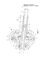
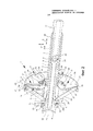
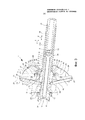
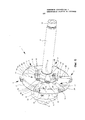
Фиг. 1-3 схематические изображения в разрезе предлагаемого зажимного устройства при установлении центрирующих элементов зажимного устройства в минимальное центрирующее положение (Фиг. 1), в среднее центрирующее положение (Фиг. 2) и в максимальное центрирующее положение (Фиг. 3), иFIG. 1-3 schematic cross-sectional views of the proposed clamping device when setting the centering elements of the clamping device in the minimum centering position (Fig. 1), in the middle centering position (Fig. 2) and in the maximum centering position (Fig. 3), and
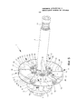
Фиг. 4-6 перспективные изображения представленного на Фиг. 1-3 зажимного устройства при установлении центрирующих элементов в минимальное центрирующее положение (Фиг. 4), в среднее центрирующее положение (Фиг. 5) и в максимальное центрирующее положение (Фиг. 6).FIG. 4-6 are perspective views of FIG. 1-3 clamping device when setting the centering elements in the minimum centering position (Fig. 4), in the middle centering position (Fig. 5) and in the maximum centering position (Fig. 6).
На Фиг. 1-6 представлено зажимное устройство 1 с центровкой по ступице для закрепления диска не изображенного колеса на также не изображенном валу балансировочного станка. Зажимное устройство 1 имеет опорный фланец 2 для упора колесного диска и несколько центрирующих элементов 3, подвижно ведомых по опорному фланцу 2 в радиальном направлении Y для центрирующего зацепления в среднее центрирующее отверстие диска. В остальном предусмотрена зажимная втулка 4, подвижно ведомая в осевом направлении X относительно опорного фланца 2, причем зажимная втулка 4 и центрирующие элементы 3 кинематически соединены таким образом, что осевое движение зажимной втулки 4 вызывает одновременное совместное движение всех центрирующих элементов 3 в радиальном направлении Y.In FIG. Figures 1-6 show a clamping device 1 centered on a hub for securing a disk of a wheel, not shown, on a balancing machine shaft, also not shown. The clamping device 1 has a
Кроме того, зажимное устройство 1 имеет жестко соединяемый с валом балансировочного станка первый трубчатый элемент с внутренним конусом 6, который сконструирован дополнительно к конусу вала балансировочного станка. Трубчатый элемент 5 соединяется с конусом вала балансировочного станка при помощи винта 7, который находится в трубчатом элементе 5 и упирается своей головкой 8 в осевую торцевую поверхность 9 трубчатого элемента 5. При помощи тут не изображенного ключа винт 7 ввинчивается своей тыльной резьбовой концевой частью во внутреннюю резьбу конуса вала, так что трубчатый элемент 5 жестко сидит на валу.In addition, the clamping device 1 has a first tubular element rigidly connected to the balancing machine shaft with an
Опорный фланец 2 привинчен при помощи дистанционных вставок 11 и винтов 12 к кольцеобразной детали 13, которая, в свою очередь, закреплена винтами 14 на трубчатом элементе 5, а именно на обращенном к валу балансировочного станка конце трубчатого элемента 5 в средней области внутреннего конуса 6. Таким образом, опорный фланец 2 неподвижно закреплен на трубчатом элементе 5 в осевом направлении X и радиальном направлении Y.The supporting
На зажимной втулке имеются два участка подшипника скольжения 15, так что зажимная втулка 4 подвижно ведома в осевом направлении X на внешней поверхности трубчатого элемента 5. Как видно из Фиг. 1-6, для кинематического соединения зажимной втулки 4 с центрирующими элементами 3 предусмотрены зажимные рычаги 16, причем каждый центрирующий элемент 3 имеет шарнирное соединение с зажимной втулкой при помощи зажимного рычага 16. Зажимные рычаги 16 и центрирующие элементы 3 образуют коленно-рычажную систему, причем движение зажимной втулки 4 в осевом направлении X относительно опорного фланца 2 вызывает соединенное совместное смещение всех центрирующих элементов в радиальном направлении Y. Это становится ясно при сравнении Фиг. 1-3 и 4-6. Изображенное зажимное устройство благодаря коленно-рычажной системе обеспечивает передачу высокого центрирующего усилия, причем прилагаемое при затягивании диска к опорному фланцу 2 усилие одновременно используется для центрирования диска. При притягивании диска к опорному фланцу 2 зажимная втулка 4 при помощи непредставленной зажимной гайки подтягивается в направлении к диску, так что центрирующие элементы 3 смещаются наружу, вследствие чего, в конце концов, диск центрируется и закрепляется. При этом возможно плавное центрирование различных дисков с различными осевыми диаметрами.There are two sections of sliding
В представленной модели зажимного устройства 1 имеется шесть центрирующих элементов 3. Каждый центрирующий элемент 3 образован направляющим сегментом 17 и центрирующим сегментом 18, изогнутым от направляющего сегмента 17 в осевом направлении к диску. Направляющие сегменты 17 передвигаются в Т-образных радиальных пазах 19 опорного фланца 2 и имеют соответственную геометрию сечения, так что центрирующие элементы 3 смещаются в радиальном направлении Y на опорном фланце 2 и удерживаются в осевом направлении X на опорном фланце 2. При этом центрирующие элементы 3 при помощи осевого смещения зажимной втулки 4 передвигаются из минимального центрирующего положения, изображенного на Фиг. 1 и 4, в максимальное центрирующее положение, изображенное на Фиг. 3 и 6. В максимальном центрирующем положении концы 20 центрирующих элементов 17 выступают наружу над бортиком опорного фланца 2 в радиальном направлении. В остальном центрирующие сегменты 18 при достижении максимального центрирующего положения максимально удалены от зажимной втулки 4 и настроены на максимально возможный осевой диаметр. Каждый зажимной рычаг 16 шарнирно соединен своей внешней концевой частью 22 с концевой частью 20 центрирующего элемента 3. Внутренняя концевая часть 23 каждого зажимного рычага 16 шарнирно соединена с задней концевой частью зажимной втулки 4 и упирается при этом в минимальном центрирующем положении центрирующих элементов 3 в наклонную поверхность 24а утолщения 24 зажимной втулки 4, что изображено на Фиг. 1. Тем самым достигается простая настройка и высокая передача усилия в коленно-рычажной системе, которую образуют зажимные рычаги 16 и центрирующие элементы 3.In the presented model of the clamping device 1 there are six centering
Как видно из Фиг. 1, угол зажима α между каждым зажимным рычагом 16 и соответственно соединенным центрирующим элементом 3 при расположении центрирующих элементов 3 в минимальном центрирующем положении, т.е. в минимально радиально смещенном наружу положении, составляет преимущественно приблизительно 45°. Из Фиг. 3 видно, что угол зажима α при расположении центрирующего элемента 3 в максимальном центрирующем положении, т.е. в максимально радиально смещенном наружу положении, составляет в основном приблизительно 15°. Любой угол зажима α плавно настраивается между вышеупомянутыми диапазонами угла при максимальном и минимальном положениях центрирующих элементов. Угол зажима α в рамках настоящего раскрытия (изобретения) соответственно соотносится к продольной оси Z1 центрирующего элемента 3 и к продольной оси Z2 зажимного рычага 16.As can be seen from FIG. 1, the clamping angle α between each clamping
Как далее видно из Фиг. 1-6, ровные внешние поверхности 26 направляющих сегментов 17 и поверхность прилегания 25 опорного фланца 2 могут быть соосными. Поверхность прилегания 25 и внешние поверхности 26 центрирующих элементов 3 упираются в таком случае вместе в диск в центрированном зафиксированном положении диска.As can further be seen from FIG. 1-6, the smooth
Как далее видно из Фиг. 1-3, на центрирующем элементе 3 может иметься фаска 27 на обращенной от диска стороне, в которую упирается прикрепленный зажимной рычаг 16 в максимальном центрирующем положении центрирующего элемента 3, что представлено на Фиг. 3. При этом зажимной рычаг 16 проходит через продолговатое отверстие 28 на опорном фланце 2 и своей концевой частью 23 соединяется с зажимной втулкой 4.As can further be seen from FIG. 1-3, the centering
Центрирующие сегменты 18 центрирующих элементов 3 вместе образуют цилиндрическую внешнюю поверхность для центрирующего зацепления в среднее центрирующее отверстие диска. В центрированном и зафиксированном на опорном фланце 2 состоянии диск упирается фронтально в опорную поверхность 25 опорного фланца 2, в то время как центрирующие сегменты 18, образующие круговые сегменты, с дугообразными радиальными внешними поверхностями 29 упираются во внутреннюю поверхность центрирующего отверстия.The centering
Для фиксации диска на сегмент наружной резьбы 30 зажимной втулки 4 навинчивается зажимная гайка, причем усилия сжатия приводят к тому, что зажимная втулка 4 протягивается относительно опорного фланца 2 в направлении диска либо по чертежу направо, так что зажимные рычаги 16 давят на центрирующие элементы в радиальном направлении наружу, пока внешние поверхности 29 центрирующих сегментов 18 не будут прилегать центрирующе к внутренней поверхности центрирующего отверстия.To fix the disk, the clamping nut is screwed onto the
Внутри зажимной втулки 4 предусмотрен подвижный в осевом направлении X относительно зажимной втулки 4 и опирающийся на первый трубчатый элемент 5 второй трубчатый элемент 31, причем второй трубчатый элемент 31 имеет сегмент наружной резьбы 31а, а зажимная втулка - соответствующий сегмент внутренней резьбы, и второй трубчатый элемент 31 ввинчивается в зажимную втулку 4. Второй трубчатый элемент 31 можно вручную вкрутить в зажимную втулку 4, чтобы тем самым обеспечить быстрое перемещение центрирующих элементов 3 для предварительной настройки на определенный осевой диаметр диска. Кроме того, на втором трубчатом элементе 31 имеется отверстие для ключа 33 на торцевом внутреннем конце, так что снаружи можно вставить ключ сквозь второй трубчатый элемент 31 и отверстие для ключа 33 в шестигранный сегмент винта 7. Отверстие для ключа 33 также имеет шестигранный контур. Поскольку наружная резьба 32 винта 7 и сегмент наружной резьбы 31а на втором трубчатом элементе 31 имеют одинаковый шаг, то винт 7 и второй трубчатый элемент 31 могут вместе регулироваться при помощи ключа в осевом направлении X.Inside the clamping
Для получения возможности фиксировать на опорном фланце 2 и центрировать диски с большим осевым диаметром, при установлении центрирующих элементов 3 в максимальное центрирующее положение расстояние а между сегментом наружной резьбы 31 зажимной втулки 4, который, преимущественно, тянется до области утолщения 24, и осевыми торцевыми поверхностями 36 на центрирующих сегментах 18 центрирующих элементов 3 в осевом направлении X составляет, преимущественно, меньше 30 мм, что изображено на Фиг. 3.In order to be able to fix disks with a large axial diameter on the
Claims (10)
Applications Claiming Priority (3)
| Application Number | Priority Date | Filing Date | Title |
|---|---|---|---|
| DE102012017789.5A DE102012017789B4 (en) | 2012-09-10 | 2012-09-10 | Clamping device with centering |
| DE102012017789.5 | 2012-09-10 | ||
| PCT/EP2013/002288 WO2014037074A2 (en) | 2012-09-10 | 2013-08-01 | Clamping device having hub centring |
Publications (2)
| Publication Number | Publication Date |
|---|---|
| RU2590840C1 RU2590840C1 (en) | 2016-07-10 |
| RU2590840C9 true RU2590840C9 (en) | 2016-12-20 |
Family
ID=49111097
Family Applications (1)
| Application Number | Title | Priority Date | Filing Date |
|---|---|---|---|
| RU2015108159/11A RU2590840C9 (en) | 2012-09-10 | 2013-08-01 | Clamping device with alignment of wheel hub |
Country Status (10)
| Country | Link |
|---|---|
| US (1) | US10132708B2 (en) |
| EP (1) | EP2893313B1 (en) |
| AU (1) | AU2013312019B2 (en) |
| CA (1) | CA2889096C (en) |
| DE (1) | DE102012017789B4 (en) |
| ES (1) | ES2608862T3 (en) |
| PL (1) | PL2893313T3 (en) |
| RU (1) | RU2590840C9 (en) |
| WO (1) | WO2014037074A2 (en) |
| ZA (1) | ZA201501695B (en) |
Families Citing this family (5)
| Publication number | Priority date | Publication date | Assignee | Title |
|---|---|---|---|---|
| DE202013006029U1 (en) | 2013-07-05 | 2014-10-15 | Haweka Ag | Electromagnetic direct drive for a tire balancing machine |
| US11333569B2 (en) * | 2018-09-14 | 2022-05-17 | Akron Special Machinery, Inc. | Dynamic balancer with a frameless motor drive |
| CN112207307B (en) * | 2020-09-27 | 2023-04-28 | 东风汽车零部件(集团)有限公司活塞轴瓦分公司 | Clamping device for turning and milling combined machining of gear box gear shifting hub and combined machine tool |
| RU2766067C1 (en) * | 2021-03-16 | 2022-02-07 | ООО Научно-производственное объединение "Компания Сивик" | Device for quick fastening of a wheel on a balancing machine |
| CN114559280A (en) * | 2021-12-08 | 2022-05-31 | 中国航空工业集团公司北京航空精密机械研究所 | Clamping tool for preventing deformation in machining of tiny slender shaft parts |
Citations (3)
| Publication number | Priority date | Publication date | Assignee | Title |
|---|---|---|---|---|
| US5292139A (en) * | 1991-12-10 | 1994-03-08 | Gamet Precision, S.A. | Clamping chuck for a machine tool, especially an automatic machine tool, and a method for preparing it |
| DE19724523C1 (en) * | 1997-06-11 | 1998-06-04 | Haweka Gmbh | Quick clamping nut for securing vehicle rim to balancing machine |
| DE102004044287B3 (en) * | 2004-09-10 | 2005-08-25 | Warkotsch, Horst | Quick release fastener e.g. for attachment to vehicle wheel on balancing machine, has flange for connecting to rim of vehicle wheel and clamp for tightening rim against flange with cone has internal drill for pushing onto balancing machine |
Family Cites Families (12)
| Publication number | Priority date | Publication date | Assignee | Title |
|---|---|---|---|---|
| US1181355A (en) * | 1915-06-18 | 1916-05-02 | Firestone Tire & Rubber Co | Universal chuck. |
| US1548227A (en) * | 1921-10-17 | 1925-08-04 | Warner Swasey Co | Chuck |
| US1839401A (en) * | 1929-09-12 | 1932-01-05 | Baird Machine Co | Outward gripping chuck |
| US1959081A (en) * | 1932-03-21 | 1934-05-15 | Kelsey Hayes Wheel Corp | Chuck |
| US2277128A (en) * | 1938-09-16 | 1942-03-24 | President And Directors Of The | Machine for making paper containers |
| US2784002A (en) * | 1954-05-10 | 1957-03-05 | Walter L Stace | Fluid-actuated chuck |
| US3131946A (en) * | 1962-01-02 | 1964-05-05 | Budd Co | Draw-bar actuated centering device |
| US3380747A (en) * | 1965-05-13 | 1968-04-30 | Woodworth Co N A | Adjustable compensating and centralizing chuck |
| US3919889A (en) * | 1975-01-22 | 1975-11-18 | Ammco Tools Inc | Rotor balancing apparatus |
| US5562007A (en) * | 1994-12-16 | 1996-10-08 | Hayes Wheels International, Inc. | Wheel mounting fixture for double bead seat machining |
| US6481281B1 (en) * | 2000-07-07 | 2002-11-19 | Hunter Engineering Company | Wheel mount chuck and wheel mount method for vehicle wheel balancers |
| US20060266105A1 (en) * | 2005-05-16 | 2006-11-30 | Hunter Engineering Company | Wheel balancer system with automatic wheel clamping and wheel centering |
-
2012
- 2012-09-10 DE DE102012017789.5A patent/DE102012017789B4/en active Active
-
2013
- 2013-08-01 US US14/427,094 patent/US10132708B2/en active Active
- 2013-08-01 CA CA2889096A patent/CA2889096C/en not_active Expired - Fee Related
- 2013-08-01 EP EP13756308.6A patent/EP2893313B1/en not_active Not-in-force
- 2013-08-01 WO PCT/EP2013/002288 patent/WO2014037074A2/en active Application Filing
- 2013-08-01 PL PL13756308T patent/PL2893313T3/en unknown
- 2013-08-01 RU RU2015108159/11A patent/RU2590840C9/en not_active IP Right Cessation
- 2013-08-01 ES ES13756308.6T patent/ES2608862T3/en active Active
- 2013-08-01 AU AU2013312019A patent/AU2013312019B2/en not_active Ceased
-
2015
- 2015-03-12 ZA ZA2015/01695A patent/ZA201501695B/en unknown
Patent Citations (3)
| Publication number | Priority date | Publication date | Assignee | Title |
|---|---|---|---|---|
| US5292139A (en) * | 1991-12-10 | 1994-03-08 | Gamet Precision, S.A. | Clamping chuck for a machine tool, especially an automatic machine tool, and a method for preparing it |
| DE19724523C1 (en) * | 1997-06-11 | 1998-06-04 | Haweka Gmbh | Quick clamping nut for securing vehicle rim to balancing machine |
| DE102004044287B3 (en) * | 2004-09-10 | 2005-08-25 | Warkotsch, Horst | Quick release fastener e.g. for attachment to vehicle wheel on balancing machine, has flange for connecting to rim of vehicle wheel and clamp for tightening rim against flange with cone has internal drill for pushing onto balancing machine |
Also Published As
| Publication number | Publication date |
|---|---|
| WO2014037074A3 (en) | 2014-04-24 |
| CA2889096C (en) | 2017-02-14 |
| WO2014037074A2 (en) | 2014-03-13 |
| ZA201501695B (en) | 2016-01-27 |
| DE102012017789B4 (en) | 2017-03-23 |
| AU2013312019B2 (en) | 2016-04-14 |
| EP2893313A2 (en) | 2015-07-15 |
| CA2889096A1 (en) | 2014-03-13 |
| US10132708B2 (en) | 2018-11-20 |
| US20150241294A1 (en) | 2015-08-27 |
| DE102012017789A1 (en) | 2014-03-13 |
| RU2590840C1 (en) | 2016-07-10 |
| PL2893313T3 (en) | 2017-04-28 |
| ES2608862T3 (en) | 2017-04-17 |
| EP2893313B1 (en) | 2016-10-05 |
| AU2013312019A1 (en) | 2015-04-30 |
Similar Documents
| Publication | Publication Date | Title |
|---|---|---|
| RU2590840C1 (en) | Clamping device with alignment of wheel hub | |
| RU2564460C2 (en) | Actuator with pressure bar for compact modules with disc brake support with threaded part resting directly on actuator body | |
| US8931973B2 (en) | Arrangement and method for connecting an accessory part to an operating table | |
| SE512225C2 (en) | Fixture | |
| RU2013138312A (en) | FOLDING STICK, IN PARTICULAR, FOR SCANDINAVIAN WALKING | |
| JP6216075B2 (en) | Sensor device and disc brake equipped with sensor device | |
| RU2410576C2 (en) | Device and procedure for assembly of objects on walls of vehicle | |
| US20130081915A1 (en) | Pressure Plate Assembly And Method For Power Transmission | |
| RU2377471C1 (en) | Heater installation device | |
| US9568037B2 (en) | Machine element mounting assembly | |
| JP7170719B2 (en) | emergency wheel | |
| CA2767677A1 (en) | Fastening device for attachment to a mounting rail | |
| US11473617B2 (en) | Sliding bearing for a steering spindle and steering column for a motor vehicle | |
| US10449990B2 (en) | Clamp mechanism | |
| US6854944B2 (en) | Quick mounting nut | |
| KR920019487A (en) | Coupling force adjusting device for clamp device | |
| US10648593B2 (en) | Pipe clamp | |
| GB2473876A (en) | Barrier clamp | |
| US20170106770A1 (en) | Connecting arrangement for a linkage of a vehicle seat, and vehicle seat | |
| CN109746870B (en) | Double-end stud screwing device | |
| RU2191310C2 (en) | Valve, thermostatic valve in particular for heating appliances | |
| JP2518156Y2 (en) | Strut rod | |
| US20230134740A1 (en) | Nut for securing a component to a support | |
| US20230383773A1 (en) | Device for compensating for tolerances between two components to be connected to one another | |
| RU2020102484A (en) | FASTENER FOR MOUNTING ON MOUNTING PROFILE |
Legal Events
| Date | Code | Title | Description |
|---|---|---|---|
| TH4A | Reissue of patent specification | ||
| TK4A | Correction to the publication in the bulletin (patent) |
Free format text: AMENDMENT TO CHAPTER -FG4A- IN JOURNAL: 19-2016 FOR TAG: (73) |
|
| MM4A | The patent is invalid due to non-payment of fees |
Effective date: 20200802 |