RU2583452C2 - Directed detection of resistive ground fault and rupture of conductor of medium voltage - Google Patents
Directed detection of resistive ground fault and rupture of conductor of medium voltage Download PDFInfo
- Publication number
- RU2583452C2 RU2583452C2 RU2012123514/07A RU2012123514A RU2583452C2 RU 2583452 C2 RU2583452 C2 RU 2583452C2 RU 2012123514/07 A RU2012123514/07 A RU 2012123514/07A RU 2012123514 A RU2012123514 A RU 2012123514A RU 2583452 C2 RU2583452 C2 RU 2583452C2
- Authority
- RU
- Russia
- Prior art keywords
- voltage
- phase
- detection
- medium voltage
- low voltage
- Prior art date
Links
Images


Classifications
-
- H—ELECTRICITY
- H02—GENERATION; CONVERSION OR DISTRIBUTION OF ELECTRIC POWER
- H02H—EMERGENCY PROTECTIVE CIRCUIT ARRANGEMENTS
- H02H5/00—Emergency protective circuit arrangements for automatic disconnection directly responsive to an undesired change from normal non-electric working conditions with or without subsequent reconnection
- H02H5/10—Emergency protective circuit arrangements for automatic disconnection directly responsive to an undesired change from normal non-electric working conditions with or without subsequent reconnection responsive to mechanical injury, e.g. rupture of line, breakage of earth connection
-
- G—PHYSICS
- G01—MEASURING; TESTING
- G01R—MEASURING ELECTRIC VARIABLES; MEASURING MAGNETIC VARIABLES
- G01R31/00—Arrangements for testing electric properties; Arrangements for locating electric faults; Arrangements for electrical testing characterised by what is being tested not provided for elsewhere
- G01R31/50—Testing of electric apparatus, lines, cables or components for short-circuits, continuity, leakage current or incorrect line connections
- G01R31/52—Testing for short-circuits, leakage current or ground faults
-
- H—ELECTRICITY
- H02—GENERATION; CONVERSION OR DISTRIBUTION OF ELECTRIC POWER
- H02H—EMERGENCY PROTECTIVE CIRCUIT ARRANGEMENTS
- H02H1/00—Details of emergency protective circuit arrangements
- H02H1/0061—Details of emergency protective circuit arrangements concerning transmission of signals
Abstract
Description
ОБЛАСТЬ ТЕХНИКИFIELD OF TECHNOLOGY
Изобретение относится к детектированию замыканий в распределительных электрических сетях, в частности в сетях среднего напряжения. В частности, изобретение предлагает принцип детектирования резистивных замыканий между электрическим проводником среднего напряжения и землей, замыкания, вызванного, например, разрывом проводников, а также соответствующее устройство.The invention relates to the detection of short circuits in distribution electric networks, in particular in medium voltage networks. In particular, the invention proposes the principle of detecting resistive short circuits between an electric medium-voltage conductor and ground, a short circuit caused, for example, by rupture of conductors, as well as a corresponding device.
ПРЕДШЕСТВУЮЩИЙ УРОВЕНЬ ТЕХНИКИBACKGROUND OF THE INVENTION
Как показано на фиг.1, электрические распределительные сети 1 могут быть разбиты на несколько уровней, с сетями 2 передачи и распределения сверхвысокого и высокого напряжения СВН/ВН на первом уровне (от 35 до более 200 кВ), используемыми для передачи или распределения электроэнергии от электростанций на большие расстояния. Распределительная сеть 5 среднего напряжения СН, обычно в диапазоне от 1 до 35 кВ, более точно с напряжением 11 кВ между фазой и нейтралью во Франции, берет на себя передачу меньшей мощности потребителям промышленного типа и подстанциям 10, 20, 30, преобразующим высокое напряжение в низкое напряжение НН (в частности, 0,4 кВ во Франции). Низкое напряжение 15, 25, 35 поставляется клиентам с низкой потребностью в электроэнергии с помощью трехфазных проводов 15А, 15B, 15C и нейтрального провода 15N.As shown in figure 1, the
Электрическая сеть 5 СН может быть образована воздушными линиями и/или подземными кабелями. Независимо от структуры, сеть 5 подвержена различным замыканиям, которые важно детектировать и локализовать, чтобы уменьшить возникающие из-за них проблемы: отключение электроэнергии, нарушение прочности изоляционных материалов или безопасность людей. Среди этих замыканий 7 наиболее частыми являются однофазные замыкания, происходящие за пределами первичной подстанции, при которых фаза находится в контакте с землей или происходит разрыв воздушного кабеля, в частности из-за неблагоприятных погодных условий.The
Эти замыкания 7, как и многофазные замыкания, которые затрагивают несколько фаз, относятся к типу короткого замыкания и в начале имеют высокие токи, которые могут достигать нескольких тысяч или десятков тысяч ампер, в то время как провода и/или оборудование, как правило, предназначены для того, чтобы выдерживать несколько сотен ампер в номинальном режиме. Например, когда нейтраль N трансформатора непосредственно заземлена, ток замыкания соответствует напряжению сети 5, поделенному на сумму сопротивлений цепи, которая является очень низкой.These
Один из вариантов детектирования такого рода замыкания заключается в измерении протекающего тока или относящихся к нему параметров. Тем не менее, эти измерения должны быть выполнены с помощью измерений трехфазных напряжений, если задано соответствующее направление (со стороны линии или со стороны нагрузки) по отношению к оборудованию детектирования замыкания. Тем не менее, напряжение сети 5 СН приводит к усложнению доступа к точкам измерения и проблемам изоляции электронного оборудования: такой тип детектирования направления трудно реализовать.One of the options for detecting this kind of circuit is to measure the flowing current or related parameters. However, these measurements should be performed using three-phase voltage measurements if the appropriate direction (line side or load side) is specified with respect to the circuit detection equipment. However, the voltage of the 5 CH network leads to a complication of access to measurement points and problems of isolation of electronic equipment: this type of direction detection is difficult to implement.
Кроме того, детектирование тока короткого замыкания само по себе может стать сложным. В частности, заземление сети СН, как правило, выполняется с помощью импеданса: ограничительный элемент типа сопротивления или катушки компенсации вставляется между нейтральной точкой N вторичной обмотки трансформатора 3 и землей в целях повышения общего импеданса на пути тока замыкания, чтобы таким образом уменьшить ток. Это снижает нагрузку на компоненты сети 5, а также обеспечивает защиту людей. В этом случае должны быть сделаны более тонкие измерения тока (чувствительные к замыканию на землю).In addition, detecting a short circuit current in itself can be difficult. In particular, the grounding of the CH network is usually carried out by means of an impedance: a limiting element such as a resistance or compensation coil is inserted between the neutral point N of the secondary winding of the
Кроме того, другие элементы являются ответственными за ограничение значения тока замыкания и усложняют детектирование: сопротивление земли является одним из факторов, который следует принять во внимание, поскольку свойственно природе замыкания 7. Однако, хотя параметры заземления могут быть учтены путем регулировки настроек оборудования защиты и детектирования во время выполнения установки, то же самое нельзя сказать о характеристиках замыкания, которые являются непредсказуемыми. Среди замыканий, которые наиболее сложно детектировать, в особенности имеет место разрыв проводника СН, который может произойти с контактом или без контакта с землей.In addition, other elements are responsible for limiting the value of the fault current and complicate the detection: earth resistance is one of the factors that should be taken into account, as it is characteristic of the nature of
Для таких замыканий с высоким сопротивлением, таким образом, реализовано детектирование через напряжение. Например, документ ЕР 1603211 относится к коммуникационному оборудованию, установленному на концах линии. Детектирование обрыва проводника осуществляется простым детектированием потери напряжения линии. Теоретические исследования указывают на возможность использования обратного напряжения и/или напряжения нулевой последовательности в сети 5 СН. Тем не менее, проблемы, связанные с измерением напряжения на ранее упомянутых средневольтных фазных проводниках, остаются полностью нерешенными.For such high-resistance circuits, voltage detection is thus implemented. For example, EP 1603211 relates to communication equipment installed at the ends of a line. A wire break detection is carried out by simple detection of line voltage loss. Theoretical studies indicate the possibility of using reverse voltage and / or zero sequence voltage in a 5 SN network. However, the problems associated with measuring voltage on the previously mentioned medium-voltage phase conductors remain completely unsolved.
Таким образом, очевидно, что детектирование и локализация резистивных замыканий в сети среднего напряжения, в частности в случае обрыва проводника, практически не развивались в связи с использованием сложно реализуемых измерений, в частности переключатели напряжений в проводниках среднего напряжения и точные измерения токов короткого замыкания, протекающих в последних.Thus, it is obvious that the detection and localization of resistive faults in the medium voltage network, in particular in the case of a wire break, practically did not develop due to the use of difficult to implement measurements, in particular, voltage switches in medium voltage conductors and accurate measurements of short-circuit currents flowing in the latter.
КРАТКОЕ ИЗЛОЖЕНИЕ СУЩЕСТВА ИЗОБРЕТЕНИЯSUMMARY OF THE INVENTION
Среди других преимуществ задачей изобретения является смягчить некоторые недостатки существующих систем детектирования и предложить преимущественно детектирование направления резистивных замыканий на землю в сетях среднего напряжения, особо сосредоточившись на разрыве проводников. В частности, изобретение предполагает использование измерений в низковольтной системе распределения электроэнергии, на стороне нагрузки от СН/ВН подстанции для детектирования и идентификации замыкания со стороны среднего напряжения.Among other advantages, the object of the invention is to mitigate some of the shortcomings of existing detection systems and to offer mainly detection of the direction of resistive earth faults in medium voltage networks, focusing especially on the gap of conductors. In particular, the invention involves the use of measurements in a low-voltage power distribution system, on the load side of the substation MV / HV, for detecting and identifying short circuits on the medium voltage side.
Согласно одному аспекту, изобретение относится к способу детектирования резистивных замыканий на землю, в частности замыканий из-за разрыва проводника, в электрических распределительных сетях среднего напряжения, снабжающих множество линий передач низкого напряжения. Способ содержит определение обратных напряжений для каждой линии передачи, соответствующих симметричной составляющей фазных напряжений, сравнение амплитуды этих обратных напряжений с пороговым значением, которое преимущественно является регулируемым, и указание на возникновение замыкания, когда превышение порогового значения происходит, по меньшей мере, один раз.According to one aspect, the invention relates to a method for detecting resistive earth faults, in particular faults due to a wire break, in medium voltage electrical distribution networks supplying a plurality of low voltage transmission lines. The method includes determining reverse voltages for each transmission line corresponding to a symmetrical component of phase voltages, comparing the amplitude of these reverse voltages with a threshold value that is predominantly adjustable, and indicating the occurrence of a short circuit when the threshold value is exceeded at least once.
Согласно другому аспекту, способ детектирования связан с относительным расположением детектируемого замыкания. Для этого фазовые напряжения обрабатываются, и результат обработки позволяет определить, находится ли детектируемое замыкание со стороны линии или со стороны нагрузки от точки измерения. В частности, определяются стандарт или амплитуда фазных напряжений каждой линии передачи, также как и их среднее значение и их минимальное значение для каждой линии передачи. Среднее значение сравнивается с амплитудами, а минимальное значение сравнивается с пороговым значением.According to another aspect, the detection method is related to the relative location of the detected circuit. To do this, the phase voltages are processed, and the processing result allows you to determine whether the detected circuit is on the line side or on the load side from the measurement point. In particular, the standard or amplitude of the phase voltages of each transmission line is determined, as well as their average value and their minimum value for each transmission line. The average value is compared with the amplitudes, and the minimum value is compared with the threshold value.
Согласно еще одному аспекту, изобретение относится к устройству, соответствующему способу детектирования и предпочтительно для вышеуказанного способа направленного детектирования, подходящего для электрических сетей среднего напряжения, которые содержат, по меньшей мере, одну трансформаторную подстанцию среднего напряжения/низкого напряжения, определяющую линию передачи, обеспечивающую множество фазных проводов низкого напряжения.According to another aspect, the invention relates to a device corresponding to a detection method, and preferably for the above directional detection method, suitable for medium voltage electrical networks, which contain at least one medium voltage / low voltage transformer substation defining a transmission line providing a plurality of phase wires of low voltage.
Согласно одному аспекту изобретения вышеупомянутое устройство объединяется в систему для возможности контроля в электрических сетях среднего напряжения. Для этого устройство принимает образцы сигналов напряжений каждого проводника каждой линии передачи с возможностью их обработки, или множество устройств встраивается на уровне каждой линии передачи, или возможно любое другое сочетание, например, с устройством, выполненным с возможностью приема информации относительно ветви электрической сети. Система дополнительно содержит средство, указывающее на появление замыкания, и предпочтительно относительное расположение последнего на стороне линии или на стороне нагрузки по отношению к точкам поступления сигналов, принятых системой.According to one aspect of the invention, the aforementioned device is integrated into a system for monitoring in medium voltage electrical networks. For this, the device receives samples of voltage signals of each conductor of each transmission line with the possibility of their processing, or many devices are integrated at the level of each transmission line, or any other combination is possible, for example, with a device configured to receive information on the branch of the electric network. The system further comprises means indicative of the occurrence of a fault, and preferably the relative position of the latter on the line side or on the load side with respect to the points of arrival of the signals received by the system.
В частности, устройство для детектирования резистивного замыкания на землю содержит средство для приема образцов сигналов напряжения каждого проводника линии передачи низкого напряжения, средство для получения образцов сигналов фазных напряжений из принятых сигналов напряжения, средство для определения симметричной составляющей обратного напряжения линии передачи, средство для сравнения обратного напряжения с порогом срабатывания, и, предпочтительно, средство для настройки порога срабатывания. Устройством детектирования предпочтительно оборудована каждая из снабжаемых линий передачи низкого напряжения, в частности оно располагается в трансформаторной подстанции, и система, образованная таким образом, содержит средство для индикации возникновения замыкания в электрических сетях среднего напряжения, когда средство сравнения одного из устройств детектирования выдает результат, в котором модуль обратного напряжения превышает порог срабатывания.In particular, a device for detecting a resistive earth fault contains a means for receiving samples of voltage signals of each conductor of the low voltage transmission line, means for receiving samples of phase voltage signals from the received voltage signals, means for determining a symmetrical component of the reverse voltage of the transmission line, means for comparing the reverse voltage with a threshold, and, preferably, means for setting a threshold. Preferably, each of the supplied low voltage transmission lines is equipped with a detection device, in particular it is located in a transformer substation, and the system thus formed contains means for indicating the occurrence of short circuits in medium voltage electrical networks when the means for comparing one of the detection devices outputs a result, which the reverse voltage module exceeds the threshold.
Альтернативно, система для детектирования резистивного замыкания в электрических сетях среднего напряжения в соответствии с изобретением содержит, по меньшей мере, одно устройство детектирования, имеющее средства, которые способны принимать образец сигнала напряжения каждого проводника каждой линии передачи низкого напряжения, получать образцы сигналов фазных напряжений каждой линии передачи, определять симметричную составляющую обратного напряжения последних и сравнивать модуль каждого обратного напряжения с порогом переключения, а также средство для указания возникновения замыкания в электрических сетях среднего напряжения, когда средство сравнения дает результат, в котором обратное напряжение превышает порог переключения.Alternatively, a system for detecting a resistive circuit in medium voltage electrical networks in accordance with the invention comprises at least one detection device having means that are capable of receiving a voltage signal sample of each conductor of each low voltage transmission line, and receiving phase voltage signal samples of each line transmission, determine the symmetrical component of the reverse voltage of the latter and compare the module of each reverse voltage with the threshold switched Iya, as well as means for indicating the occurrence of short circuits in medium voltage electrical networks when the means of comparison gives a result in which the reverse voltage exceeds the switching threshold.
В случае, когда нейтраль трансформаторных подстанций среднего напряжения/низкого напряжения является заземленной, система согласно изобретению дополнительно содержит датчики напряжения на каждом фазном проводе и на нейтральном проводе.In the case where the neutral of the medium / low voltage transformer substations is grounded, the system according to the invention further comprises voltage sensors on each phase wire and on the neutral wire.
Устройство согласно изобретению преимущественно выполнено с возможностью направленного детектирования резистивного замыкания, дополнительно содержит средство обработки образцов сигналов фазных напряжений и средство для интерпретации результатов обработки сигналов для определения того, что замыкание произошло со стороны линии или со стороны нагрузки от точки измерения сигналов, принятых упомянутым устройством. В частности, средство обработки содержит средство для вычисления нормы фазных напряжений, средство для вычисления средней нормы, средство для определения минимальной нормы, первое средство для сравнения норм фазных напряжений со своим средним значением и второе средство для сравнения минимальной нормы с пороговым значением.The device according to the invention is preferably configured to directionally detect a resistive fault, further comprises means for processing samples of phase voltage signals and means for interpreting the results of the signal processing to determine that the fault has occurred on the line side or on the load side from the measuring point of the signals received by the said device. In particular, the processing means comprises means for calculating the norm of phase voltages, means for calculating the average norm, means for determining the minimum norm, first means for comparing the norms of phase voltages with its average value, and second means for comparing the minimum norm with the threshold value.
КРАТКОЕ ОПИСАНИЕ ЧЕРТЕЖЕЙBRIEF DESCRIPTION OF THE DRAWINGS
В дальнейшем изобретение поясняется описанием предпочтительных вариантов воплощения изобретения со ссылками на сопроводительные чертежи, на которых:The invention is further explained in the description of the preferred embodiments of the invention with reference to the accompanying drawings, in which:
Фиг.1 изображает электрическую сеть, на которой используется детектирование согласно изобретению;Figure 1 depicts an electrical network that uses detection according to the invention;
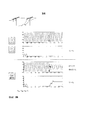
Фиг.2А, 2В и 2С изображают проявления различных замыканий напряжений линий НН;Figa, 2B and 2C depict the manifestations of various voltage short circuits of LV lines;
Фиг.3 изображает схематически этапы способа согласно варианту осуществления изобретения;Figure 3 depicts schematically the steps of a method according to an embodiment of the invention;
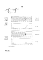
Фиг.4 изображает устройство детектирования направления согласно предпочтительному варианту осуществления изобретения.4 depicts a direction detecting device according to a preferred embodiment of the invention.
ОПИСАНИЕ ПРЕДПОЧТИТЕЛЬНЫХ ВАРИАНТОВ ОСУЩЕСТВЛЕНИЯ ИЗОБРЕТЕНИЯDESCRIPTION OF THE PREFERRED EMBODIMENTS OF THE INVENTION
Когда происходит резистивное замыкание на землю 7 в электрической сети 5 СН, напряжение, протекающее в последней, искажается, по меньшей мере, в рассматриваемой фазе, и эти нарушения могут быть определены на уровне электрических сетей 15, 25, 35 НН, распределяемых электрической сетью 5 СН. В многофазных энергосистемах 1, описанных ранее на фиг.1, детектирование замыкания согласно изобретению осуществляется посредством устройств 100, 200, 300 направленного детектирования на уровне каждой линии передачи НН.When there is a
В иллюстрированном предпочтительном варианте осуществления и предпочтительном варианте использования изобретения, устройство 100 связано с каждым трансформатором 10, который содержит три фазных провода 15A, 15B, 15C и нейтральный провод 15N. Однако от этой идеальной ситуации можно отойти, и энергосистема может содержать другое число фаз, в частности нейтраль может быть компенсированной.In the illustrated preferred embodiment and preferred embodiment of the invention, the
В случае резистивного замыкания 7 в электрической сети 5 СН, представляются три варианта - устройства 100 детектирования направления связаны с неповрежденными линиями передачи 15, устройства 200 расположены на стороне линии от замыкания 7 и устройства 300 находятся на стороне нагрузки от замыкания 7. Замыкание 7 создает очевидное искажение напряжения V фаз, что имеет влияние со стороны нагрузки относительно упомянутого замыкания. Тем не менее, в некоторых случаях могут быть повреждены другие фазы на стороне линии энергосистем НН или даже исправные линии передачи 15.In the case of
В частности, на фиг.2 показаны замыкания в случае воздушных трехфазных энергосистем, графическое представление было сохранено, замыкание на стороне линии расположено на чертеже слева. Могут быть идентифицированы шесть видов замыканий (отбрасываем случай трех оборванных проводников, поскольку тогда отсутствует информация электрической природы, и рассматриваются только одновременные замыкания):In particular, figure 2 shows the faults in the case of air three-phase power systems, a graphical representation has been saved, the fault on the line side is located in the drawing on the left. Six types of faults can be identified (we discard the case of three dangling conductors, because then there is no information of an electrical nature, and only simultaneous faults are considered):
i) разрыв на уровне перемычки, элемента, который дает возможность обойти изоляторы на каждой стороне столба, поддерживающего линии (т.е. замыкание 7 бесконечного сопротивления без заземляющего проводника);i) a gap at the level of the jumper, an element that makes it possible to bypass the insulators on each side of the column supporting the line (i.e.,
ii) разрыв одного проводника с заземлением со стороны линии;ii) rupture of one conductor with grounding on the line side;
iii) разрыв одного проводника с заземлением со стороны нагрузки;iii) rupture of one conductor with grounding on the load side;
iv) разрыв двух проводников, один из которых заземлен на стороне линии, а другой на стороне нагрузки;iv) rupture of two conductors, one of which is earthed on the line side and the other on the load side;
v) разрыв двух проводников с заземлением на стороне нагрузки;v) rupture of two conductors with grounding on the load side;
vi) разрыв двух проводников с заземлением на стороне линии.vi) rupture of two conductors with grounding on the line side.
В других случаях, например при заземленном проводнике и разорванной перемычке, фактически, одно из двух событий предшествует другому и будет детектировано заранее.In other cases, for example, with a grounded conductor and a broken jumper, in fact, one of the two events precedes the other and will be detected in advance.
В первых четырех случаях i), ii), iii) и iv), как показано на фиг.2A, подвергается влиянию только напряжение V на стороне нагрузки от замыкания 7. Одна из фаз остается неизменной, а амплитуда напряжений двух других фаз снижается. В случае v) при разрыве двух проводов с заземлением на стороне нагрузки (фиг.2B) влияние оказывается только на напряжение на стороне нагрузки, с уменьшением напряжения каждой фазы, одна из них даже исключается. С другой стороны, в случае vi) разрыва двух проводников с заземлением на стороне линии, также присутствуют изменения напряжения на стороне линии 25 и даже на исправной линии 15 передачи с полным исключением на стороне нагрузки 35.In the first four cases i), ii), iii) and iv), as shown in FIG. 2A, only the voltage V on the load side from
Для каждой точки измерений возможно вычислить симметричные составляющие напряжения (Vd прямое напряжение, Vi обратное напряжение и V0 напряжение нулевой последовательности для фазных напряжений VAN, VBN, VCN) с помощью матрицы Фортескью:For each measurement point, it is possible to calculate the symmetrical voltage components (V d forward voltage, V i reverse voltage and V 0 zero sequence voltage for phase voltages V AN , V BN , V CN ) using the Fortescue matrix:

Можно отметить, что во всех вышеупомянутых случаях замыканий, что модуль обратного напряжения Vi превышает пороговое значение Sd, которое может быть установлено между 4 и 20% от номинального тока, желательно на уровне 12%, по меньшей мере, в одной из точек 100, 200, 300 измерений. Таким образом, наличие замыкания можно детектировать, вычисляя эту симметричную составляющую. В случае с энергосистемой с n фазами, приведенные выше формулы, в частности в матрице Фортескью, должны быть корректированы путем замены цифры 3 на n.It can be noted that in all the aforementioned cases of short circuits, the reverse voltage module V i exceeds a threshold value S d that can be set between 4 and 20% of the rated current, preferably at 12%, at least at one of the
Детектированное замыкание находится на стороне нагрузки от точки измерения, за исключением ситуации vi), когда только линии 25 передачи со стороны линии и неповрежденные линии 15 передачи указывают на его присутствие. Чтобы локализовать замыкание 7 по отношению к точке 100, 200, 300 измерения, важно установить последний случай vi), в котором Vi300 <Sd. Может быть установлено, что только в первых четырех случаях i), ii), iii), iv) и не в проблемном случае vi), для точки измерения при замыкании со стороны нагрузки, среднее значение µ между амплитудами фазных напряжений больше двух номинальных значений ||Vxn||. Кроме того, чтобы различать два оставшихся случая v) и vi), для которых среднее между амплитудами фазных напряжений ниже двух номинальных значений, будь то замыкание 7 на стороне линии или на стороне нагрузки, может быть установлено, что точка измерения на стороне нагрузки от замыкания указывает, что, по меньшей мере, одно из фазных напряжений исключается, то есть минимальная Vmin из амплитуд фазных напряжений ||Vxn|| ниже порогового значения Sv. Таким образом, можно, зная только фазные напряжения, определить, находится ли детектированное замыкание со стороны линии или со стороны нагрузки от измерения.The detected fault is on the load side of the measuring point, except in situation vi), when only
Таким образом, принцип детектирования и расположения согласно изобретению основаны на измерении фазных напряжений в распределенных энергосистемах 15, 25, 35 НН исключительно для детектирования резистивного замыкания типа разрыва проводников с помощью обратного напряжения, затем относительной локализации замыкания с помощью амплитуд. На первом этапе, как показано на Фиг.3, измеряются напряжения каждой фазы VA, VB, Vc в энергосистемах 15, 25, 35 НН, как и напряжение нейтрали VN. Обратная симметричная составляющая Vi определяется с помощью подходящей формулы. Если обратное напряжение Vi не превышает порог переключения Sd, тогда в энергосистеме, напрямую снабжающей линию передачи, замыкание не детектировано, и измерение возобновляется через определенные промежутки времени для непрерывного контроля.Thus, the principle of detection and location according to the invention is based on the measurement of phase voltages in distributed
Когда обратное напряжение Vi превышает порог переключения Sd, идентифицируется резистивное замыкание и может быть реализован второй этап метода, т.е. определение направления местоположения. Простое детектирование возникновения замыкания может быть доведено до сведения пользователей с помощью зажигания диода или с помощью другой системы оповещения.When the reverse voltage V i exceeds the switching threshold S d , a resistive circuit is identified and the second step of the method can be implemented, i.e. determination of the direction of location. Simple detection of a fault can be brought to the attention of users using the ignition diode or using another warning system.
Чтобы найти замыкание 7 на стороне линии или на стороне нагрузки от точки измерения напряжений Vxn, для каждой фазы X определяются амплитуды ||Vxn|| напряжений, например среднее квадратичное или другие, и вычисляется их среднее арифметическое µ. Если, по крайней мере, две нормы ||Vxn|| превышают среднее μ, то замыкание 7 имеет место на стороне линии от точки 300 измерения. В противном случае, вычисляются минимальные значения Vmin фазных напряжений амплитудой ||Vxn||, и если это минимальное значение Vmin превышает пороговое значение Sv, установленное, например, на уровне 5% от номинального значения энергосистемы, то замыкание 7 имеет место на стороне линии от точки 300 измерения, в противном случае - на стороне нагрузки.To find the
Расположение замыкания 7 на стороне нагрузки от точки измерения в действительности относится как к исправной линии 15 передачи, так и трансформатору 20, расположенному на поврежденной линии. Однако затем легко идентифицировать ветвь электрической сети 5 СН, где произошло замыкание, учитывая, что это единственная линия передачи для которой, по меньшей мере, один из установленных датчиков 300 не указывает на замыкание. Замыкание на самом деле произошло в L между двумя точками измерений, одной - соответствующей всем вышеперечисленным критериям, и другой - не соответствующей последнему.The location of the
В результате D, L могут быть указаны непосредственно на уровне трансформаторных подстанций путем зажигания диодов, в частности, разного цвета, или с помощью централизованной системы удаленного типа на функциональной схеме электрической сети 1, например, для дистанционной индикации в центр управления.As a result, D, L can be indicated directly at the level of transformer substations by ignition of diodes, in particular of different colors, or by using a centralized system of a remote type on the functional diagram of
В заключение, с помощью этого принципа индикации можно найти замыкание 7, которое во всех случаях и в любой ситуации находится между "горящим" детектором и "негорящим" детектором. Детектирование резистивного замыкания на землю, разрыва проводника СН выполняется без датчиков тока (и, следовательно, без низкого предела детектирования) с помощью измерителей напряжения, установленных в сети НН, которые, в дополнение к простоте установки, обеспечивают лучшую точность измерения.In conclusion, using this principle of indication, you can find
Средство 50 детектирования в виде датчика напряжения устанавливается таким образом на каждой линии передачи НН, в частности на уровне трансформаторов 10, 20, 30 НН, питаемых электрической сетью 5 СН. Они связаны с системой контроля в электрической сети СН, содержащей устройства 100, 200, 300 детектирования направления, обеспечивая обработку информации от каждой линии передачи, причем упомянутые устройства 100, 200, 300 имеют возможность быть встроенными в каждый трансформатор 10, 20, 30 или образуют часть центральной системы, в которую передается информация от каждого датчика 50. Данные от этих устройств 100, 200, 300 направленного детектирования дают возможность выявления относительного расположения замыкания между двумя устройствами. На фиг.4 проиллюстрирован предпочтительный вариант осуществления устройства, подходящего для реализации способа согласно изобретению.The detection means 50 in the form of a voltage sensor is installed in this way on each LV transmission line, in particular at the level of
Устройство 100 направленного детектирования согласно изобретению содержит средство 110 для получения образцов сигналов фазных напряжений VA, VB, VC, VN, предоставляемых датчиками 50 и принятых соответствующим средством устройства 100. В предпочтительном варианте осуществления сигналы, предварительно отфильтрованные соответствующим средством 112, таким как аналоговый фильтр, Vaf, VBf, Vcf, Vnf обрабатываются дополнительно и средство 110 для получения образцов сигналов содержит модуль 114 дискретизации, работающий, в частности, с частотой более 1 кГц, тем самым выдавая фильтрованные сигналы дискретизации Vaf*, Vвf*, Vcf* на средство 116 вычисления комплексных векторов, позволяя получить фазные напряжения VAN, VBN, VCN. Следует отметить, что если нейтраль энергосистемы НН не распределяется, то использование измерения напряжений между фазами UAB, UBC, UCA позволяет восстановить искусственную нейтраль с помощью преобразования "треугольник-звезда".The
Сигналы Vxn, приходящие из средства 110 получения, передаются в блок 120 детектирования замыкания 7, который, в частности, содержит средство 122 для определения, по меньшей мере, одного из Vi симметричных составляющих напряжения, в частности, с помощью матрицы Фортескью. Модуль обратного напряжения |Vi|, определяется соответствующим средством 124. Блок 120 детектирования содержит средство 126 для сравнения модуля обратного напряжения с порогом детектирования Sd, если пороговое значение будет превышено, то детектировано замыкание D и активируется блок 130 обработки. Главным образом, средство 128 предназначено для регулировки порога переключения Sd, в частности, во Франции между 4 и 20% от номинального значения.The signals V xn coming from the receiving means 110 are transmitted to the
Блок 130 обработки принимает сигналы VaN, Vbn, Vcn от средства 110 получения. Он содержит средство 132 для вычисления их нормы (или амплитуды, среднеквадратичного значения или другого) ||VAN||, ||VBN||, ||VCN||. Полученное значение передается на первое средство 134 для сравнения минимума нормы Vmin с пороговым значением Sv. Параллельным образом, полученные нормы ||VAN||, ||VBN||, ||VCN|| последовательно передаются в средство 136 вычисления среднего арифметического µ трех входных данных и на второе средство 138 сравнения, которое содержит четвертый вход, соответствующий вычисленному среднему µ. Средства 132, 138 сравнения подключены к средству 140 интерпретации, на выходе которого появляется сигнал L направленного детектирования замыкания на землю на стороне нагрузки или на стороне линии от датчиков 50 согласно результатам интерпретации.The
Второе средство 138 сравнения сравнивает каждую норму ||Vxп|| со своим средним µ и предпочтительно выдает двоичный сигнал согласно направлению сравнения на средство 140 интерпретации. В предпочтительном варианте осуществления, средство 140 интерпретации или второе средство 138 сравнения содержит средство суммирования двоичных результатов сравнения.A
Элементы 110, 120, 130 устройства направленного детектирования могут быть сгруппированы вместе в устройстве, которое может быть, например, объединено с четырьмя датчиками 50 и находиться в трансформаторной подстанции СН/НН. Они также могут быть разделены при помощи, например, средства 110 получения, связанного с датчиками 50 в трансформаторной подстанции, и блоками детектирования и обработки, интегрированными в центр управления, при этом фазные напряжения автоматически или не автоматически передаются в эти блоки. В частности, каждый из блоков 110, 120, 130 может обрабатывать множество линий передач, одновременно либо последовательно и содержать подходящие запоминающие устройства.The
Таким образом, согласно изобретению средство для измерения напряжения каждого проводника устанавливается на линиях передачи НН предпочтительно на уровне каждого трансформатора, питаемого от электрической сети СН, которую необходимо контролировать. Средство измерения выполнено с возможностью измерения напряжения каждой фазы и напряжения нейтрали. Полученные сигналы передаются на одно или несколько устройств детектирования, которые выполнены с возможностью определения результирующего обратного напряжения и амплитуды. Решение согласно изобретению представляет преимущество рассмотрения проблемы обрыва проводников СН, позиционируя себя с точки зрения напряжений в энергосистеме НН, где измерительные приборы проще, и рассматривая исчерпывающим образом весь диапазон возможных ситуаций для одного или нескольких поврежденных проводников (для трехфазной энергосистемы).Thus, according to the invention, a means for measuring the voltage of each conductor is installed on the LV transmission lines, preferably at the level of each transformer, powered from the mains MV, which must be controlled. The measuring means is configured to measure the voltage of each phase and the voltage of the neutral. The received signals are transmitted to one or more detection devices, which are configured to determine the resulting reverse voltage and amplitude. The solution according to the invention represents the advantage of considering the problem of open circuit breakers of the MV, positioning itself in terms of voltages in the LV power system, where measuring devices are simpler, and considering in an exhaustive way the entire range of possible situations for one or more damaged conductors (for a three-phase power system).
Система или способ согласно изобретению могут быть связаны с защитными устройствами электрической сети 5, например защитным реле, которое расцепляет и изолирует замкнутые ветви энергосистемы, в случае детектирования замыкания в упомянутой ветви.The system or method according to the invention can be connected to the protective devices of the
Согласно другому варианту, может быть предусмотрена отложенная индикация, например, при помощи журнала событий. Любой вид прямой, локальной или удаленной, немедленной или отложенной индикации или любой более радикальный тип действия может быть связан с детектированием согласно изобретению.According to another embodiment, a delayed indication may be provided, for example, using an event log. Any kind of direct, local or remote, immediate or delayed indication or any more radical type of action may be associated with the detection according to the invention.
Хотя изобретение было описано со ссылкой на воздушные электрические сети, оно никоим образом не ограничивается ими. Изобретение находит такое же применение и те же варианты осуществления в частично или полностью подземных электрических сетях, где обрыв кабеля может произойти после повреждения или износа изоляторов или повреждения других компонентов, которые могут быть затронуты изобретением. Кроме того, элементы, представленные для выполнения вышеупомянутых функций, могут быть заменены эквивалентами. В частности, напряжение может быть измерено любым типом датчика (резистивный, емкостной, электрическое поле,...), и средства обработки сигналов могут принимать соответствующие формы, в частности, для вычисления обратного напряжения.Although the invention has been described with reference to overhead electrical networks, it is by no means limited to them. The invention finds the same application and the same embodiments in partially or completely underground electrical networks, where cable breakage can occur after damage or deterioration of insulators or damage to other components that may be affected by the invention. In addition, elements presented to perform the aforementioned functions may be replaced by equivalents. In particular, the voltage can be measured by any type of sensor (resistive, capacitive, electric field, ...), and the signal processing means can take appropriate forms, in particular, for calculating the reverse voltage.
Claims (16)
- средство для приема образцов сигналов напряжений каждого проводника линии передачи (15) низкого напряжения;
- средство (110) для получения образцов сигналов фазных напряжений (VAN, BBN, VCN) из принятых сигналов напряжения;
- средство (122) для определения симметричной составляющей обратного напряжения (Vi) линии передачи;
- средство (126) для сравнения обратного напряжения (Vi) с порогом (SD) срабатывания.1. A device (100) for detecting a resistive circuit (7) to earth in a medium voltage electrical network 5, which contains at least one medium voltage / low voltage transformer substation (10) defining a transmission line (15) comprising a plurality phase wires (15A, 15V, 15C) of low voltage, containing:
- means for receiving samples of voltage signals of each conductor of the transmission line (15) low voltage;
- means (110) for obtaining samples of phase voltage signals (V AN , B BN , V CN ) from the received voltage signals;
- means (122) for determining the symmetrical component of the reverse voltage (V i ) of the transmission line;
- means (126) for comparing the reverse voltage (V i ) with a threshold (S D ) of operation.
- по меньшей мере, одно устройство (100) детектирования по п.1 или 2, средства (110, 122, 126) упомянутого устройства (100) детектирования, выполненные с возможностью приема образцов сигналов напряжений каждого проводника каждой линии (15, 25, 35) передачи низкого напряжения, получения образцов сигналов фазных напряжений каждой линии (15, 25, 35) передачи, определения симметричной составляющей обратного напряжения (Vi) и сравнения модуля каждого обратного напряжения (Vi) с порогом (SD) срабатывания, и
- средство для индикации (D) возникновения замыкания (7) в электрической сети (5) среднего напряжения, когда средство сравнения (126) дает результат, в котором обратное напряжение (Vi) превышает порог (SD) срабатывания.3. A system for detecting a resistive circuit (7) in a medium voltage electric network (5), which contains a plurality of transformer substations (10, 20, 30) medium voltage / low voltage, each of which defines a transmission line (15, 25, 35) providing for many phase wires (15A, 15V, 15C) low voltage, the specified system contains:
at least one detection device (100) according to claim 1 or 2, means (110, 122, 126) of said detection device (100), configured to receive voltage signal samples of each conductor of each line (15, 25, 35 ) transmitting low voltage, obtaining samples of phase voltage signals of each transmission line (15, 25, 35), determining the symmetrical component of the reverse voltage (V i ) and comparing the module of each reverse voltage (V i ) with a threshold (S D ) of operation, and
- means for indicating (D) the occurrence of a short circuit (7) in the medium voltage electric network (5) when the means of comparison (126) gives a result in which the reverse voltage (V i ) exceeds the threshold (S D ) of operation.
- средство (132) для вычисления норм фазных напряжений (||VAN||, ||VBN||, ||VCN||);
- средство (136) для вычисления среднего (µ) норм (||VAN||, ||VBN||, ||VCN||);
- средство для определения минимума норм (Vmin);
- первое средство (138) для выполнения сравнения нормы фазных напряжений с их средним (µ);
- второе средство (134) для выполнения сравнения минимума норм с пороговым значением (Sv).9. The directional detection device according to claim 8, in which the processing means (130) comprises:
- means (132) for calculating phase voltage norms (|| V AN ||, || V BN ||, || V CN ||);
- means (136) for calculating the average (μ) norms (|| V AN ||, || V BN ||, || V CN ||);
- a tool for determining the minimum standards (V min );
- the first means (138) for comparing the norms of phase voltages with their average (µ);
- second means (134) for comparing the minimum of norms with a threshold value (S v ).
получают напряжения от каждой фазы линий (15, 25, 35) передачи низкого напряжения, питаемых электрической сетью (5) среднего напряжения;
определяют обратные напряжения (Vi) линий передачи низкого напряжения;
сравнивают модули обратных напряжений (Vi) с пороговым значением (Sd); и
указывают возникновение замыкания (7), когда, по меньшей мере, одно сравнение показывает, что пороговое значение (SD) было превышено.13. A method for detecting a resistive circuit (7) to earth in a medium voltage electrical network (5), comprising the steps of:
receiving voltages from each phase of the low voltage transmission lines (15, 25, 35) fed by the medium voltage electric network (5);
determining reverse voltages (V i ) of the low voltage transmission lines;
comparing the modules of the reverse voltages (V i ) with a threshold value (S d ); and
indicate the occurrence of a fault (7) when at least one comparison indicates that the threshold value (S D ) has been exceeded.
Applications Claiming Priority (2)
| Application Number | Priority Date | Filing Date | Title |
|---|---|---|---|
| FR1101730A FR2976363B1 (en) | 2011-06-07 | 2011-06-07 | DIRECTIONAL DETECTION OF RESISTANT LAND FAULT AND MEDIUM VOLTAGE CONDUCTOR BREAK |
| FR1101730 | 2011-06-07 |
Publications (2)
| Publication Number | Publication Date |
|---|---|
| RU2012123514A RU2012123514A (en) | 2013-12-20 |
| RU2583452C2 true RU2583452C2 (en) | 2016-05-10 |
Family
ID=46027881
Family Applications (1)
| Application Number | Title | Priority Date | Filing Date |
|---|---|---|---|
| RU2012123514/07A RU2583452C2 (en) | 2011-06-07 | 2012-06-06 | Directed detection of resistive ground fault and rupture of conductor of medium voltage |
Country Status (7)
| Country | Link |
|---|---|
| EP (1) | EP2533060B1 (en) |
| CN (1) | CN102818969B (en) |
| AU (1) | AU2012203278B2 (en) |
| ES (1) | ES2511644T3 (en) |
| FR (1) | FR2976363B1 (en) |
| PL (1) | PL2533060T3 (en) |
| RU (1) | RU2583452C2 (en) |
Families Citing this family (12)
| Publication number | Priority date | Publication date | Assignee | Title |
|---|---|---|---|---|
| FR2993670B1 (en) | 2012-07-20 | 2014-07-11 | Schneider Electric Ind Sas | DIRECTIONAL DETECTION OF SENSITIVE LAND DEFECT MEDIUM VOLTAGE BY LINEAR CORRELATION |
| CN103698647B (en) * | 2013-12-23 | 2016-06-22 | 广东电网公司茂名供电局 | A kind of automatic testing method of Single-phase Earth Fault of Power System |
| FR3023429A1 (en) | 2014-07-02 | 2016-01-08 | Schneider Electric Ind Sas | MODULAR TELE-CONDUCT EQUIPMENT |
| FR3023444B1 (en) | 2014-07-02 | 2018-02-16 | Schneider Electric Industries Sas | POWER MODULE FOR MODULAR TELE-DRIVING EQUIPMENT AND EQUIPMENT COMPRISING IT |
| FR3026492B1 (en) * | 2014-09-29 | 2016-10-28 | Schneider Electric Ind Sas | DIRECTIONAL DETECTION OF EARTH FAULT IN AN ELECTRICAL DISTRIBUTION NETWORK |
| CN105589008B (en) * | 2014-11-18 | 2019-02-19 | 德信东源电力技术服务(北京)有限公司 | Open phase fault detection method and device |
| CN105738767B (en) * | 2016-02-26 | 2018-03-27 | 李景禄 | A kind of single-phase transition resistance earth fault phase selection method of partition type power distribution network |
| TWI641854B (en) * | 2017-06-23 | 2018-11-21 | 宏碁股份有限公司 | Fault warning circuit |
| CN108051696A (en) * | 2017-12-11 | 2018-05-18 | 李玉诚 | A kind of detection method for detection device connection status |
| CN108717151A (en) * | 2018-05-31 | 2018-10-30 | 佛山市梅雨科技有限公司 | A kind of power grid fault detection system |
| FR3083322B1 (en) | 2018-06-28 | 2021-06-25 | Electricite De France | SYSTEM AND METHOD FOR LOCATING FAULT ON A POLIPHASE ELECTRICAL NETWORK USING DIRECT AND REVERSE VOLTAGE EVOLUTION |
| CN115792600A (en) * | 2022-09-29 | 2023-03-14 | 华能国际电力股份有限公司上海石洞口第二电厂 | Automatic alarm method and device for three-phase current measurement errors of motor |
Citations (4)
| Publication number | Priority date | Publication date | Assignee | Title |
|---|---|---|---|---|
| RU2263925C2 (en) * | 2000-11-08 | 2005-11-10 | Дженерал Электрик Компани | Method and device for detecting short-circuit ground and calculating its resistance |
| EP1603211A1 (en) * | 2004-06-01 | 2005-12-07 | Marjan Bezjak | Detection and disconnection device for broken covered conductor in medium voltage electrical network |
| EP1894283A1 (en) * | 2005-06-22 | 2008-03-05 | Siemens Aktiengesellschaft | Fault current analyser for detecting a fault current and a fault current detection device |
| RU2374733C1 (en) * | 2008-11-27 | 2009-11-27 | Владимир Григорьевич Наровлянский | Method for determining short circuit in electric power system |
Family Cites Families (6)
| Publication number | Priority date | Publication date | Assignee | Title |
|---|---|---|---|---|
| US5343155A (en) * | 1991-12-20 | 1994-08-30 | The Research And Development Institute, Inc. At Montana State University | Fault detection and location system for power transmission and distribution lines |
| US7099130B2 (en) * | 2003-01-17 | 2006-08-29 | Ericson Manufacturing Company | Voltage monitor for ground fault circuit interrupter |
| CN101023366B (en) * | 2004-06-04 | 2011-01-19 | Fmc技术有限公司 | A method of monitoring line faults in a medium voltage network |
| CN101452039A (en) * | 2007-11-29 | 2009-06-10 | 上海蓝瑞电气有限公司 | Earth fault synthesis diagnostic equipment for medium pressure electrical power distribution network |
| CN101858948B (en) * | 2009-04-10 | 2015-01-28 | 阿海珐输配电英国有限公司 | Method and system for carrying out transient and intermittent earth fault detection and direction determination in three-phase medium-voltage distribution system |
| CN101871989A (en) * | 2009-04-23 | 2010-10-27 | 上海市南供电设计有限公司 | Voltage and current regulating device for use in grounding fault diagnosis of medium-voltage distribution network |
-
2011
- 2011-06-07 FR FR1101730A patent/FR2976363B1/en not_active Expired - Fee Related
-
2012
- 2012-04-27 EP EP12354028.8A patent/EP2533060B1/en active Active
- 2012-04-27 PL PL12354028T patent/PL2533060T3/en unknown
- 2012-04-27 ES ES12354028.8T patent/ES2511644T3/en active Active
- 2012-06-04 AU AU2012203278A patent/AU2012203278B2/en active Active
- 2012-06-06 RU RU2012123514/07A patent/RU2583452C2/en active
- 2012-06-07 CN CN201210186466.6A patent/CN102818969B/en active Active
Patent Citations (4)
| Publication number | Priority date | Publication date | Assignee | Title |
|---|---|---|---|---|
| RU2263925C2 (en) * | 2000-11-08 | 2005-11-10 | Дженерал Электрик Компани | Method and device for detecting short-circuit ground and calculating its resistance |
| EP1603211A1 (en) * | 2004-06-01 | 2005-12-07 | Marjan Bezjak | Detection and disconnection device for broken covered conductor in medium voltage electrical network |
| EP1894283A1 (en) * | 2005-06-22 | 2008-03-05 | Siemens Aktiengesellschaft | Fault current analyser for detecting a fault current and a fault current detection device |
| RU2374733C1 (en) * | 2008-11-27 | 2009-11-27 | Владимир Григорьевич Наровлянский | Method for determining short circuit in electric power system |
Also Published As
| Publication number | Publication date |
|---|---|
| CN102818969A (en) | 2012-12-12 |
| ES2511644T3 (en) | 2014-10-23 |
| FR2976363A1 (en) | 2012-12-14 |
| PL2533060T3 (en) | 2014-11-28 |
| AU2012203278B2 (en) | 2014-07-10 |
| EP2533060A1 (en) | 2012-12-12 |
| FR2976363B1 (en) | 2013-05-24 |
| EP2533060B1 (en) | 2014-07-30 |
| RU2012123514A (en) | 2013-12-20 |
| CN102818969B (en) | 2017-06-09 |
| AU2012203278A1 (en) | 2013-01-10 |
Similar Documents
| Publication | Publication Date | Title |
|---|---|---|
| RU2583452C2 (en) | Directed detection of resistive ground fault and rupture of conductor of medium voltage | |
| US8861155B2 (en) | High-impedance fault detection and isolation system | |
| US8884467B2 (en) | System and method for protecting an electrical power grid | |
| EP2335082B1 (en) | Method and apparatus for dynamic signal switching of a merging unit in an electrical power system | |
| RU2631025C2 (en) | Detection of direction of weakly resistant short circuit to earth of average voltage with help of linear correlation | |
| EP2206208B1 (en) | Differential protection method, system and device | |
| US10802054B2 (en) | High-fidelity voltage measurement using a capacitance-coupled voltage transformer | |
| EP3465860A1 (en) | Method and apparatus for detecting faults in a three-phase electrical distribution network | |
| CN111226363B (en) | Method and device for identifying fault sections in a multi-terminal hybrid line | |
| CN108614180B (en) | Single-phase earth fault line searching method | |
| US10345363B2 (en) | High-fidelity voltage measurement using resistive divider in a capacitance-coupled voltage transformer | |
| Hong et al. | Detection of open conductor fault using multiple measurement factors of feeder RTUs in power distribution networks with DGs | |
| Velayudham et al. | Locating ground fault in distribution systems using smart meter | |
| US20100097736A1 (en) | Method and an apparatus for protecting a bus in a three-phase electrical power system | |
| Venkata et al. | Advanced and adaptive protection for active distribution grid | |
| Kokor et al. | Effects of neutral point grounding methods on single-phase short circuit fault characteristics | |
| Menezes et al. | Dual-Layer Based Microgrid Protection Using Voltage Synchrophasors | |
| Kotulla et al. | Measuring of fault distance using the fault locator function of protection relay | |
| González de Miguel et al. | Enhancing reliability in medium voltage distribution networks with directional fault passage indicators without voltage sensors | |
| Łowczowskia et al. | Utilization of Cable Screen Earthing Current for Detection and Location of Earth Faults in Medium Voltage Networks | |
| Pocthier et al. | Improve your SAIDI with Advanced Fault Passage Indication | |
| RU2312442C2 (en) | Method for protecting multiple-cable line of alternating-voltage network against single-phase ground fault | |
| Bo et al. | Integrated protection of distribution lines using transient comparison technique | |
| NETWORK | DEPARTMENT OF ELECTRICAL ENGINEERING CERTIFICATE | |
| SPEED | Balamourougan Vinayagam |