RU2582002C1 - Holder for attachment of control device to container - Google Patents
Holder for attachment of control device to container Download PDFInfo
- Publication number
- RU2582002C1 RU2582002C1 RU2014149118/12A RU2014149118A RU2582002C1 RU 2582002 C1 RU2582002 C1 RU 2582002C1 RU 2014149118/12 A RU2014149118/12 A RU 2014149118/12A RU 2014149118 A RU2014149118 A RU 2014149118A RU 2582002 C1 RU2582002 C1 RU 2582002C1
- Authority
- RU
- Russia
- Prior art keywords
- holder
- control device
- cable
- cavity
- parts
- Prior art date
Links
- 239000004033 plastic Substances 0.000 claims description 6
- HQQADJVZYDDRJT-UHFFFAOYSA-N ethene;prop-1-ene Chemical group C=C.CC=C HQQADJVZYDDRJT-UHFFFAOYSA-N 0.000 claims description 3
- 238000009434 installation Methods 0.000 abstract description 8
- 230000000694 effects Effects 0.000 abstract 1
- 239000000126 substance Substances 0.000 abstract 1
- 238000004519 manufacturing process Methods 0.000 description 7
- 239000002184 metal Substances 0.000 description 3
- 238000010276 construction Methods 0.000 description 2
- 238000003780 insertion Methods 0.000 description 2
- 230000037431 insertion Effects 0.000 description 2
- 239000000463 material Substances 0.000 description 2
- 229910000831 Steel Inorganic materials 0.000 description 1
- 238000005452 bending Methods 0.000 description 1
- 239000000470 constituent Substances 0.000 description 1
- 238000010586 diagram Methods 0.000 description 1
- 238000005516 engineering process Methods 0.000 description 1
- 239000007788 liquid Substances 0.000 description 1
- 230000035939 shock Effects 0.000 description 1
- 239000010959 steel Substances 0.000 description 1
Images
Classifications
-
- F—MECHANICAL ENGINEERING; LIGHTING; HEATING; WEAPONS; BLASTING
- F16—ENGINEERING ELEMENTS AND UNITS; GENERAL MEASURES FOR PRODUCING AND MAINTAINING EFFECTIVE FUNCTIONING OF MACHINES OR INSTALLATIONS; THERMAL INSULATION IN GENERAL
- F16B—DEVICES FOR FASTENING OR SECURING CONSTRUCTIONAL ELEMENTS OR MACHINE PARTS TOGETHER, e.g. NAILS, BOLTS, CIRCLIPS, CLAMPS, CLIPS OR WEDGES; JOINTS OR JOINTING
- F16B2/00—Friction-grip releasable fastenings
- F16B2/20—Clips, i.e. with gripping action effected solely by the inherent resistance to deformation of the material of the fastening
- F16B2/22—Clips, i.e. with gripping action effected solely by the inherent resistance to deformation of the material of the fastening of resilient material, e.g. rubbery material
-
- B—PERFORMING OPERATIONS; TRANSPORTING
- B65—CONVEYING; PACKING; STORING; HANDLING THIN OR FILAMENTARY MATERIAL
- B65D—CONTAINERS FOR STORAGE OR TRANSPORT OF ARTICLES OR MATERIALS, e.g. BAGS, BARRELS, BOTTLES, BOXES, CANS, CARTONS, CRATES, DRUMS, JARS, TANKS, HOPPERS, FORWARDING CONTAINERS; ACCESSORIES, CLOSURES, OR FITTINGS THEREFOR; PACKAGING ELEMENTS; PACKAGES
- B65D25/00—Details of other kinds or types of rigid or semi-rigid containers
- B65D25/38—Devices for discharging contents
-
- F—MECHANICAL ENGINEERING; LIGHTING; HEATING; WEAPONS; BLASTING
- F16—ENGINEERING ELEMENTS AND UNITS; GENERAL MEASURES FOR PRODUCING AND MAINTAINING EFFECTIVE FUNCTIONING OF MACHINES OR INSTALLATIONS; THERMAL INSULATION IN GENERAL
- F16B—DEVICES FOR FASTENING OR SECURING CONSTRUCTIONAL ELEMENTS OR MACHINE PARTS TOGETHER, e.g. NAILS, BOLTS, CIRCLIPS, CLAMPS, CLIPS OR WEDGES; JOINTS OR JOINTING
- F16B2/00—Friction-grip releasable fastenings
- F16B2/02—Clamps, i.e. with gripping action effected by positive means other than the inherent resistance to deformation of the material of the fastening
- F16B2/06—Clamps, i.e. with gripping action effected by positive means other than the inherent resistance to deformation of the material of the fastening external, i.e. with contracting action
- F16B2/08—Clamps, i.e. with gripping action effected by positive means other than the inherent resistance to deformation of the material of the fastening external, i.e. with contracting action using bands
-
- F—MECHANICAL ENGINEERING; LIGHTING; HEATING; WEAPONS; BLASTING
- F16—ENGINEERING ELEMENTS AND UNITS; GENERAL MEASURES FOR PRODUCING AND MAINTAINING EFFECTIVE FUNCTIONING OF MACHINES OR INSTALLATIONS; THERMAL INSULATION IN GENERAL
- F16B—DEVICES FOR FASTENING OR SECURING CONSTRUCTIONAL ELEMENTS OR MACHINE PARTS TOGETHER, e.g. NAILS, BOLTS, CIRCLIPS, CLAMPS, CLIPS OR WEDGES; JOINTS OR JOINTING
- F16B5/00—Joining sheets or plates, e.g. panels, to one another or to strips or bars parallel to them
- F16B5/06—Joining sheets or plates, e.g. panels, to one another or to strips or bars parallel to them by means of clamps or clips
-
- F—MECHANICAL ENGINEERING; LIGHTING; HEATING; WEAPONS; BLASTING
- F16—ENGINEERING ELEMENTS AND UNITS; GENERAL MEASURES FOR PRODUCING AND MAINTAINING EFFECTIVE FUNCTIONING OF MACHINES OR INSTALLATIONS; THERMAL INSULATION IN GENERAL
- F16M—FRAMES, CASINGS OR BEDS OF ENGINES, MACHINES OR APPARATUS, NOT SPECIFIC TO ENGINES, MACHINES OR APPARATUS PROVIDED FOR ELSEWHERE; STANDS; SUPPORTS
- F16M13/00—Other supports for positioning apparatus or articles; Means for steadying hand-held apparatus or articles
- F16M13/02—Other supports for positioning apparatus or articles; Means for steadying hand-held apparatus or articles for supporting on, or attaching to, an object, e.g. tree, gate, window-frame, cycle
-
- F—MECHANICAL ENGINEERING; LIGHTING; HEATING; WEAPONS; BLASTING
- F17—STORING OR DISTRIBUTING GASES OR LIQUIDS
- F17C—VESSELS FOR CONTAINING OR STORING COMPRESSED, LIQUEFIED OR SOLIDIFIED GASES; FIXED-CAPACITY GAS-HOLDERS; FILLING VESSELS WITH, OR DISCHARGING FROM VESSELS, COMPRESSED, LIQUEFIED, OR SOLIDIFIED GASES
- F17C13/00—Details of vessels or of the filling or discharging of vessels
Landscapes
- Engineering & Computer Science (AREA)
- General Engineering & Computer Science (AREA)
- Mechanical Engineering (AREA)
- Clamps And Clips (AREA)
- Transmission Of Braking Force In Braking Systems (AREA)
- Valves And Accessory Devices For Braking Systems (AREA)
Abstract
Description
ОБЛАСТЬ ТЕХНИКИFIELD OF TECHNOLOGY
Настоящее изобретение относится к держателю для крепления устройства управления к резервуару под давлением или аналогичному контейнеру. Изобретение главным образом предназначено для использования на тяжелых коммерческих транспортных средствах, например грузовиках и автобусах, но, конечно, оно также может использоваться на других типах транспортных средств, например строительной технике, судах и т.д., снабженных средством управления, которое предпочтительно связано с некоторым видом контейнера и должно управляться посредством троса или аналогичного вытянутого объекта. Изобретение также относится к транспортным средствам, снабженным держателем согласно изобретению.The present invention relates to a holder for attaching a control device to a pressure vessel or similar container. The invention is mainly intended for use on heavy commercial vehicles, such as trucks and buses, but, of course, it can also be used on other types of vehicles, such as construction equipment, ships, etc., equipped with a control means, which is preferably associated with some kind of container and should be controlled by a cable or similar elongated object. The invention also relates to vehicles equipped with a holder according to the invention.
УРОВЕНЬ ТЕХНИКИBACKGROUND
Тяжелые коммерческие транспортные средства в настоящее время обычно снабжаются одним или более резервуарами под давлением для хранения сжатого воздуха, который используется, например, для тормозной системы транспортного средства. Из этих резервуаров под давлением периодически должна отводиться жидкость, которая собирается в них, например, в виде конденсата, используя для этой цели по меньшей мере один дренажный клапан, расположенный на участке резервуара под давлением, который в его установленном на транспортное средство положении направлен вниз, по направлению к земле. Дренажный клапан обычно открывается вручную при помощи троса, который имеет на его внешнем конце петлю, чтобы облегчить пользователю его использование, и его другой внутренний конец закреплен в средстве приведения в действие дренажного клапана.Heavy commercial vehicles are currently usually equipped with one or more pressure tanks for storing compressed air, which is used, for example, for a vehicle braking system. From these pressure tanks, liquid must periodically be drained, which collects in them, for example, in the form of condensate, using for this purpose at least one drain valve located in the pressure tank section, which is directed downward in its installed position on the vehicle, towards the ground. The drain valve is usually opened manually with a cable that has a loop at its outer end to facilitate its use by the user, and its other inner end is fixed to the drain valve actuation means.
Во время производства/сборки транспортного средства важно, чтобы перемещение входящих в состав деталей было легким и, следовательно, экономически эффективным, а также, чтобы сами детали являлись недорогими в изготовлении и при хранении на складе, но также хорошо и надежно выполняли их предусмотренные функции, в том числе в течение долгого времени.During the production / assembly of the vehicle, it is important that the movement of the constituent parts is easy and therefore cost-effective, and that the parts themselves are inexpensive to manufacture and store in the warehouse, but also perform their intended functions well and reliably, including over time.
Резервуар или резервуары под давлением должны быть установлены так, чтобы оставаться надежно закрепленными на раме транспортного средства в их предусмотренных положениях даже в течение временных сложных условий, например, когда транспортное средство перемещается по очень неровной поверхности или попадает в аварию.The pressure tank or tanks must be installed so that they remain firmly fixed to the vehicle frame in their intended positions even during temporary difficult conditions, for example when the vehicle moves on a very uneven surface or has an accident.
Кроме того, дренажный клапан должен всегда легко открываться, и до его управляющего троса должно быть легко достать и также его установить. Резервуары под давлением в настоящее время устанавливаются на транспортные средства посредством, например, некоторого вида хомута или троса, который имеет петлю на его внешнем конце и вставляется, вместе с резиновой втулкой, через полость в кронштейне, предназначенную для этой цели. После этого внутренний конец троса должен быть зацеплен или надежно установлен в дренажный клапан, который, после установки резервуара под давлением в его предусмотренное положение в транспортном средстве, будет находиться в положении, которое закрыто и труднодоступно. После того как трос был прикреплен к дренажному клапану, резиновая втулка должна быть надежно вставлена в правильное положение в держателе для троса. Поскольку эта операция является сложной и требует точности, она отнимает много времени и, следовательно, является дорогостоящей.In addition, the drain valve should always be easy to open, and it should be easy to get to its control cable and also install it. Pressure tanks are currently installed on vehicles by, for example, some kind of clamp or cable that has a loop at its outer end and is inserted, together with a rubber sleeve, through a cavity in the bracket designed for this purpose. After that, the inner end of the cable should be hooked or securely installed in the drain valve, which, after installing the reservoir under pressure in its intended position in the vehicle, will be in a position that is closed and inaccessible. After the cable has been attached to the drain valve, the rubber sleeve must be firmly inserted into the correct position in the cable holder. Since this operation is complex and requires precision, it is time consuming and therefore expensive.
Существовали безуспешные попытки решить вышеприведенные проблемы и предложить конструкцию, которая смягчает их и ускоряет операцию установки. Недостатками известных решений является то, что они приводят к неэргономичному креплению, которое вызывает напряжение установщика и отнимает большое количество времени. Также впоследствии сложно обслуживать известные конструкции и заменять корродированные, протекающие или поврежденные дренажные клапаны или любые другие входящие в состав детали, такие как тросы и так далее, в случае необходимости. Дополнительным недостатком является то, что известные держатели являются недостаточно амортизирующими, в результате чего функционирование конструкции подвергается риску, или со временем она страдает от нежелательного износа.There have been unsuccessful attempts to solve the above problems and propose a design that softens them and speeds up the installation operation. The disadvantages of the known solutions is that they lead to non-ergonomic fastening, which causes installer stress and takes a lot of time. It is also subsequently difficult to maintain well-known structures and replace corroded, leaking or damaged drainage valves or any other parts included, such as cables and so on, if necessary. An additional disadvantage is that the known holders are not sufficiently shock absorbing, as a result of which the functioning of the structure is at risk, or over time it suffers from unwanted wear.
Предшествующий уровень техники не ссылается на какой-либо держатель для троса, который предвосхищает настоящее изобретение и который легко и экономически эффективно помогает установить, например, управляющее средство для дренажного клапана резервуара под давлением.The prior art does not refer to any cable holder that anticipates the present invention and which easily and cost-effectively helps to install, for example, control means for a pressure drain valve of a reservoir.
СУЩНОСТЬ ИЗОБРЕТЕНИЯSUMMARY OF THE INVENTION
Одна задача изобретения состоит в решении вышеупомянутых проблем и предложении держателя, который, например, предназначен для управляющего средства/устройства управления, например троса или некоторого другого удлиненного объекта, для дренажного клапана, расположенного на резервуаре под давлением, и который позволяет просто и экономически эффективно установить упомянутое управляющее средство/устройство управления.One object of the invention is to solve the aforementioned problems and provide a holder that, for example, is intended for a control means / control device, for example a cable or some other elongated object, for a drain valve located on a pressure vessel, and which allows easy and cost-effective installation said control means / control device.
Дополнительная задача изобретения состоит в том, что должна быть возможна установка устройства управления/троса в резервуар под давлением без необходимости вставки через замкнутую петлю или полость, которая усложняет работу.An additional object of the invention is that it should be possible to install the control device / cable in the tank under pressure without the need for insertion through a closed loop or cavity, which complicates the work.
Дополнительная задача изобретения состоит в том, что должна быть возможна установка устройства управления/троса за одну производственную операцию и чтобы одновременно было простым крепление средства приведения в действие дренажного клапана.An additional objective of the invention is that it should be possible to install the control device / cable in one production operation and at the same time to be easy to attach means to actuate the drain valve.
Дополнительная задача изобретения состоит в том, что устройство управления/трос должен надежно удерживаться в держателе после завершения операции установки, но при этом легко перемещаться в осевом направлении так, чтобы дренажный клапан мог быть легко открыт и закрыт на протяжении срока службы транспортного средства.An additional object of the invention is that the control device / cable must be held securely in the holder after the installation operation is completed, but it is easy to move axially so that the drain valve can be easily opened and closed over the life of the vehicle.
Дополнительная задача изобретения состоит в том, что конструкция держателя должна быть простой и содержать как можно меньше деталей.An additional objective of the invention is that the design of the holder should be simple and contain as few parts as possible.
Дополнительная задача изобретения состоит в том, что входящие в состав детали должны иметь малый вес и быть просты и недороги в изготовлении.An additional objective of the invention is that the parts included must be lightweight and simple and inexpensive to manufacture.
Эти и дополнительные задачи и преимущества достигаются согласно изобретению устройством, определенными признаками, приведенными в отличительной части независимого п.1 формулы.These and additional tasks and advantages are achieved according to the invention by the device, certain features listed in the characterizing part of the
Как упомянуто ранее, изобретение главным образом предназначено для тяжелых коммерческих транспортных средств, например грузовиков, автобусов и подобного, но также, конечно, может быть использовано в других типах транспортных средств, снабженных некоторым видом резервуара или контейнера и снабженных устройством, которое должно приводиться в действие посредством устройства управления, например троса или некоторого другого вытянутого устройства, и должно, во время работы транспортного средства, удерживаться в определенном положении относительно резервуара.As mentioned previously, the invention is mainly intended for heavy commercial vehicles, such as trucks, buses and the like, but also, of course, can be used in other types of vehicles equipped with some kind of tank or container and equipped with a device that must be driven by means of a control device, for example a cable or some other elongated device, and must, during the operation of the vehicle, be held in a certain position from ositelno tank.
Важной задачей изобретения является упрощение установки держателя и устройства управления так, чтобы ускорить изготовление и сделать его более экономически эффективным.An important objective of the invention is to simplify the installation of the holder and the control device so as to speed up production and make it more cost-effective.
Изобретение достигается держателем, выполненным из, например, пластика, такого как EPDM (этилен-пропилен монодиен) или подобного, снабженным открытым углублением так, чтобы были образованы две части, причем углубление предназначено для вставки в боковом направлении в держатель устройства управления в виде вытянутого объекта, такого как трос или подобное. Держатель дополнительно снабжен каналом для предпочтительно хомутообразного элемента, выполненного из пластика или металла, предназначенного для установки и прижатия к смежному компоненту транспортного средства, например резервуару под давлением или подобному. Когда хомутообразный элемент затянут, держатель надежно удерживается в предусмотренном положении, и внешние концы его частей также прижаты друг к другу. Таким образом, предотвращается выскальзывание устройства управления, вставленного в углубление, из держателя, но при этом обеспечивается скольжение устройства управления в осевом направлении. Это, например, облегчает управление, закрытие и открытие дренажного клапана, расположенного на резервуаре под давлением.The invention is achieved by a holder made of, for example, plastic, such as EPDM (ethylene-propylene monodiene) or the like, provided with an open recess so that two parts are formed, the recess being intended to be laterally inserted into the holder of the control device in the form of an elongated object such as a cable or the like. The holder is further provided with a channel for a preferably clamp-like element made of plastic or metal, intended to be mounted and pressed against an adjacent component of the vehicle, for example, a pressure tank or the like. When the clamp-like element is tightened, the holder is held securely in the intended position, and the outer ends of its parts are also pressed against each other. Thus, the control device inserted into the recess is prevented from slipping out of the holder, but the control device is slidable in the axial direction. This, for example, facilitates the control, closing and opening of the drain valve located on the pressure vessel.
Решение согласно изобретению приводит к более простому применению и, следовательно, более экономически эффективной установке. Это также делает решение более легким и менее дорогостоящим в применении не только во время изготовления новых транспортных средств, но также при модификации, обслуживании или замене соответствующего оборудования на существующих транспортных средствах.The solution according to the invention leads to a simpler application and, therefore, a more cost-effective installation. It also makes the solution easier and less expensive to use, not only during the manufacture of new vehicles, but also when modifying, maintaining or replacing the appropriate equipment on existing vehicles.
Дополнительные признаки и преимущества изобретения приведены в его более подробном описании, изложенном ниже, и прилагаемых чертежах, и других пунктах формулы изобретения.Additional features and advantages of the invention are set forth in its more detailed description, set forth below, and the accompanying drawings, and other claims.
КРАТКОЕ ОПИСАНИЕ ЧЕРТЕЖЕЙBRIEF DESCRIPTION OF THE DRAWINGS
Изобретение описано более подробно ниже на некоторых примерах предпочтительных вариантов его выполнения со ссылкой на прилагаемые чертежи, на которых:The invention is described in more detail below with some examples of preferred embodiments with reference to the accompanying drawings, in which:
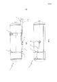
фиг. 1 - вид сбоку традиционного резервуара под давлением для сжатого воздуха, прикрепленного к раме транспортного средства посредством хомута и снабженного тросом, который предназначен для управления дренажным клапаном резервуара и который удерживается на месте посредством держателя согласно изобретению;FIG. 1 is a side view of a conventional pressurized reservoir for compressed air attached to a vehicle frame by means of a collar and equipped with a cable that is designed to control the reservoir drain valve and which is held in place by a holder according to the invention;
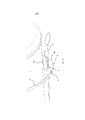
фиг. 2 - вид той же конструкции с фиг. 1, причем резервуар здесь показан снизу и без деталей рамы транспортного средства так, чтобы дренажный клапан и расположение троса были видны более ясно;FIG. 2 is a view of the same structure of FIG. 1, the tank being shown here from below and without the details of the vehicle frame so that the drain valve and the location of the cable are more clearly visible;
фиг. 3 - местный вид снизу резервуара под давлением под углом, показывая более подробно установленное положение держателя и то, как трос расположен и проходит через держатель;FIG. 3 is a partial view from below the tank under pressure at an angle, showing in more detail the position of the holder and how the cable is located and passes through the holder;
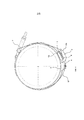
фиг. 4 - вид с конца резервуара под давлением, показывающий держатель, дренажный клапан и детали крепежного или прижимного устройства резервуара;FIG. 4 is a view from the end of the reservoir under pressure, showing the holder, drain valve, and details of the mounting or clamping device of the reservoir;
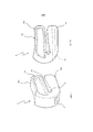
фиг. 5 - вид в перспективе под углом сбоку держателя согласно изобретению;FIG. 5 is a perspective view at an angle from the side of the holder according to the invention;
фиг. 6 - вид сбоку предпочтительного держателя согласно изобретению; иFIG. 6 is a side view of a preferred holder according to the invention; and
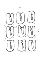
фиг. 7a-i - виды сбоку множества различных вариантов выполнения держателей согласно изобретению.FIG. 7a-i are side views of many different embodiments of holders according to the invention.
ОПИСАНИЕ ПРЕДПОЧТИТЕЛЬНЫХ ВАРИАНТОВ ВЫПОЛНЕНИЯ ИЗОБРЕТЕНИЯDESCRIPTION OF THE PREFERRED EMBODIMENTS OF THE INVENTION
Фиг. 1 изображает вид сбоку традиционного резервуара 1 под давлением для сжатого воздуха, прикрепленного к раме транспортного средства при помощи кронштейна 2 посредством хомута 3 и снабженного, например, тросом 4, который предназначен для управления дренажным клапаном 5 резервуара и удерживается на месте посредством держателя 6 согласно изобретению, который прикреплен к резервуару 1 посредством хомутообразного элемента 7.FIG. 1 is a side view of a conventional
Фиг. 2 изображает ту же конструкцию с фиг. 1, но показывая резервуар 1 снизу и без кронштейна 2 так, чтобы дренажный клапан 5 и расположение троса 4 были видны более ясно. Устройство управления или трос имеет внутренний конец, закрепленный в управляющем средстве дренажного клапана так, чтобы клапан мог быть открыт и закрыт, и внешний конец троса с петлей расположен вблизи внешней стенки резервуара, который обычно установлен сбоку транспортного средства, чтобы облегчить доступ к устройству управления/тросу. Трос проходит через держатель 6 согласно изобретению и, следовательно, легко доступен пользователю, когда необходимо выполнить дренаж.FIG. 2 shows the same construction as in FIG. 1, but showing the
Фиг. 3 изображает местный вид резервуара 1 под давлением под углом снизу, показывая более подробно установленное положение держателя 6 и то, как устройство управления/трос 4 расположен и проходит через держатель.FIG. 3 is a partial view of the
Держатель 6 предпочтительно принимает форму единого, выполненного за одно элемента, предпочтительно выполненного из пластика, например EPDM (этилен-пропилен монодиен). Он снабжен отверстием или полостью 8, которая расположена по существу по центру и предназначена для троса 4 или аналогичного средства. Полость является открытой с одной стороны держателя посредством углубления 9 таким образом, что держатель образует две части 10a, 10b, которые могут пружинить друг относительно друга. Углубление 9 предназначено для вставки вытянутого устройства управления, такого как стальной трос 4, металлический или пластиковый стержень, или аналогичного средства, выполненного из некоторого другого материала, достаточно жесткого для управления, например, дренажным клапаном. Держатель также снабжен каналом 11, который проходит через или снаружи одной из частей 10a держателя и предназначен для пластикового или металлического хомутообразного элемента 12. Хомутообразный элемент облегчает установку и прижатие держателя к или вокруг смежного компонента транспортного средства, например резервуара под давлением или подобного. Когда хомутообразный элемент надлежаще затянут, держатель прочно удерживается в его предусмотренном положении относительно части транспортного средства, в то время как его части 10a, 10b прижаты друг к другу против действия их собственного упругого усилия. Таким образом, предотвращается выскальзывание держателя из положения и предотвращается скольжение устройства управления/троса 4 в боковом направлении из держателя, но при этом обеспечивается скольжение в осевом направлении троса, то есть перпендикулярно через держатель. Таким образом, обеспечивается то, что дренажный клапан 5, расположенный на резервуаре, может быть легко открыт или закрыт.The
Фиг. 4 изображает вид сверху с одного конца резервуара 1 под давлением, показывающий держатель 6, трос 4, дренажный клапан 5 и части крепежных или прижимных устройств 3 резервуара. Она показывает хомутообразный элемент 12, продолжающийся вокруг резервуара и через внешнюю часть 10a держателя. Когда хомутообразный элемент затянут, внешняя часть 10a держателя прижата к центральному участку резервуара и, таким образом, ограничивает пространство в углублении 9 так, чтобы устройство управления/трос 4 не мог скользить в боковом направлении из держателя.FIG. 4 is a top view from one end of the
Фиг. 5 изображает вид в перспективе под углом сбоку держателя 6 согласно изобретению. Центральное отверстие 8 и углубление 9, которое открыто наружу с одной стороны, образуют две части 10a, 10b, чьи концевые участки могут быть прижаты друг к другу и предотвращать, например, выскальзывание троса (не показан) через углубление 9. Канал 11 для хомутообразного элемента (не показан) расположен в одной части 10a. Держатель может быть снабжен другими отверстиями 13, чтобы уменьшить количество материала и вес держателя, требуемого во время изготовления.FIG. 5 is a perspective view at an angle from the side of the
Фиг. 6 изображает вид сбоку держателя 6 согласно изобретению. Показано, как одна часть 10b, которая в установленном положении упирается в резервуар под давлением, имеет изгиб 14, чтобы лучше соответствовать радиусу резервуара. Этот изгиб, конечно, может быть выполнен различными способами, соответствующими компоненту, к которому предполагается крепление держателя. Схема также показывает, как канал 11 для хомутообразного элемента продолжается через внутреннюю часть 10a.FIG. 6 is a side view of the
Фиг. 7a-i показывают различные виды сбоку множества различных вариантов выполнения держателей согласно изобретению. Наиболее важным здесь является то, что упругие части 10a, 10b держателя имеют их внешние концевые области, выполненные по-разному, чтобы облегчить во время установки вставку устройства управления или троса в держатель посредством частей 10a, 10b, которые свободно открыты или, альтернативно, способны немного разжиматься, когда устройство управления/трос 4 вставляется в углубление, но после этого удерживается в центральной полости держателя, особенно после того, как хомутообразный элемент был установлен и прочно прижал держатель к резервуару под давлением и, таким образом, прижал части 10a, 10b друг к другу. Также возможно снабжение внешних концевых областей частей 10a, 10b некоторым видом ограничивающего средства 14 для предотвращения или препятствования выскальзыванию устройства управления/троса 4 из центральной полости 8 или углубления 9, когда он был надлежащим образом вставлен в углубление. Ограничивающее средство 14 на различных схемах на фиг. 7 в большинстве случаев не требует пояснений. Фиг. 7c показывает, например, круглые цилиндрические средства, прижатые друг к другу и выполняющие фиксирующую функцию. Фиг. 7i показывает треугольное средство, прижатое к полукруглому компоненту.FIG. 7a-i show various side views of a plurality of different embodiments of the holders according to the invention. Most important here is that the elastic parts of the
Вышеприведенное описание главным образом предназначено, чтобы способствовать пониманию изобретения, и, конечно, не ограничено приведенными вариантами выполнения, поскольку другие варианты изобретения также возможны и вероятны в пределах объема идеи изобретения и объема защиты пунктов формулы изобретения, изложенных ниже. Таким образом, очевидно, что можно использовать зажимные устройства, отличные от хомутообразных элементов, например элементы с круглым сечением и т.д.The above description is mainly intended to facilitate an understanding of the invention, and, of course, is not limited to the above embodiments, since other variants of the invention are also possible and probable within the scope of the inventive concept and the scope of protection of the claims set forth below. Thus, it is obvious that clamping devices other than clamp elements can be used, for example elements with a circular cross section, etc.
Claims (6)
Applications Claiming Priority (3)
| Application Number | Priority Date | Filing Date | Title |
|---|---|---|---|
| SE1250468-4 | 2012-05-08 | ||
| SE1250468A SE536482C2 (en) | 2012-05-08 | 2012-05-08 | Holder intended for fixing a control to a container |
| PCT/SE2013/050446 WO2013169177A1 (en) | 2012-05-08 | 2013-04-24 | Retainer for fixing a control device to a container |
Publications (1)
| Publication Number | Publication Date |
|---|---|
| RU2582002C1 true RU2582002C1 (en) | 2016-04-20 |
Family
ID=49551059
Family Applications (1)
| Application Number | Title | Priority Date | Filing Date |
|---|---|---|---|
| RU2014149118/12A RU2582002C1 (en) | 2012-05-08 | 2013-04-24 | Holder for attachment of control device to container |
Country Status (6)
| Country | Link |
|---|---|
| EP (1) | EP2847470B1 (en) |
| CN (1) | CN104285068B (en) |
| BR (1) | BR112014026513B1 (en) |
| RU (1) | RU2582002C1 (en) |
| SE (1) | SE536482C2 (en) |
| WO (1) | WO2013169177A1 (en) |
Citations (6)
| Publication number | Priority date | Publication date | Assignee | Title |
|---|---|---|---|---|
| SU390406A1 (en) * | 1971-05-31 | 1973-07-11 | CLAMP FOR FLEXIBLE PIPES | |
| EP0280598A1 (en) * | 1987-02-05 | 1988-08-31 | Etablissements CAILLAU | Hose clamp with an elasticity reserve |
| US4823445A (en) * | 1988-02-23 | 1989-04-25 | Diener Michael P | Storage clip |
| JPH04113007A (en) * | 1990-08-30 | 1992-04-14 | Mitsubishi Electric Home Appliance Co Ltd | Connecting tool |
| US6269985B1 (en) * | 2000-08-25 | 2001-08-07 | Delshar, Inc. | Device for securing a spray can dispensing tube |
| RU90310U1 (en) * | 2009-01-15 | 2010-01-10 | Общество с ограниченной ответственностью "Торговый дом "ИПЛАНА" | HOLDER FOR CURTAIN |
Family Cites Families (6)
| Publication number | Priority date | Publication date | Assignee | Title |
|---|---|---|---|---|
| EP1498651A3 (en) * | 2003-07-17 | 2006-04-12 | Peter Brandes | Fastening device |
| DE10352084B4 (en) * | 2003-07-17 | 2005-07-21 | Peter Brandes | Fastening element and method for fixing cables |
| US7832693B2 (en) * | 2005-12-07 | 2010-11-16 | Illinois Tool Works Inc. | Fastener |
| CN200951716Y (en) * | 2006-07-28 | 2007-09-26 | 黄南贲 | CNG gas cylinder fast fixed apparatus for automobile |
| CN201242036Y (en) * | 2008-08-15 | 2009-05-20 | 云南盛誉科技有限公司 | High pressure gas cylinder inject remote control apparatus |
| JP5290259B2 (en) * | 2010-10-29 | 2013-09-18 | 株式会社日立産機システム | Portable tank equipment |
-
2012
- 2012-05-08 SE SE1250468A patent/SE536482C2/en unknown
-
2013
- 2013-04-24 CN CN201380024118.1A patent/CN104285068B/en active Active
- 2013-04-24 EP EP13788602.4A patent/EP2847470B1/en active Active
- 2013-04-24 BR BR112014026513-5A patent/BR112014026513B1/en active IP Right Grant
- 2013-04-24 WO PCT/SE2013/050446 patent/WO2013169177A1/en active Application Filing
- 2013-04-24 RU RU2014149118/12A patent/RU2582002C1/en active
Patent Citations (6)
| Publication number | Priority date | Publication date | Assignee | Title |
|---|---|---|---|---|
| SU390406A1 (en) * | 1971-05-31 | 1973-07-11 | CLAMP FOR FLEXIBLE PIPES | |
| EP0280598A1 (en) * | 1987-02-05 | 1988-08-31 | Etablissements CAILLAU | Hose clamp with an elasticity reserve |
| US4823445A (en) * | 1988-02-23 | 1989-04-25 | Diener Michael P | Storage clip |
| JPH04113007A (en) * | 1990-08-30 | 1992-04-14 | Mitsubishi Electric Home Appliance Co Ltd | Connecting tool |
| US6269985B1 (en) * | 2000-08-25 | 2001-08-07 | Delshar, Inc. | Device for securing a spray can dispensing tube |
| RU90310U1 (en) * | 2009-01-15 | 2010-01-10 | Общество с ограниченной ответственностью "Торговый дом "ИПЛАНА" | HOLDER FOR CURTAIN |
Also Published As
| Publication number | Publication date |
|---|---|
| BR112014026513A2 (en) | 2017-06-27 |
| CN104285068A (en) | 2015-01-14 |
| EP2847470A1 (en) | 2015-03-18 |
| WO2013169177A1 (en) | 2013-11-14 |
| EP2847470A4 (en) | 2015-12-16 |
| BR112014026513B1 (en) | 2020-09-24 |
| SE1250468A1 (en) | 2013-11-09 |
| CN104285068B (en) | 2016-07-06 |
| EP2847470B1 (en) | 2019-12-04 |
| SE536482C2 (en) | 2013-12-17 |
Similar Documents
| Publication | Publication Date | Title |
|---|---|---|
| US7887012B2 (en) | Insert for tube retaining bracket | |
| US9631657B2 (en) | Fastening element and assembly with such a fastening element and a receiving element | |
| US7546986B2 (en) | Pipe hanger | |
| EP3022475B1 (en) | Pipe clip with locking feature | |
| JP5200079B2 (en) | Clamp member | |
| US20130125331A1 (en) | Windscreen wiper device | |
| KR20150028815A (en) | Fastening device for fixing a cable | |
| EP3303860B1 (en) | Bowden cable used as actuator for a functional unit in a motor vehicle | |
| CN103032500B (en) | Extension spring mounting mechanism | |
| MX2014000709A (en) | Lock for a vehicle door with a spring plate in the inlet region of the locking bolt. | |
| US8387769B2 (en) | Parking apparatus for automatic transmission | |
| US20110037252A1 (en) | Connection device for fluid lines in the region of a wall duct and wall element | |
| US10632809B2 (en) | Leaf spring retaining element for a leaf spring mounting plate | |
| RU2582002C1 (en) | Holder for attachment of control device to container | |
| CN110650855B (en) | Closing device, use thereof, method for blocking a fluid channel and air spring system | |
| KR20160128352A (en) | Accessory and method for installing same | |
| US20180187589A1 (en) | Vehicle exhaust isolator | |
| US11035467B2 (en) | Gasket for a wiper system, a gasket-bracket assembly for a wiper system comprising such a gasket, a wiper system for an automotive vehicle comprising such a gasket and a method for assembling such a gasket in a wiper system | |
| JP2010236559A (en) | Piping installation structure to vehicle body | |
| US9579944B2 (en) | System and method for attaching a control element of an air spring with internal height regulating valve | |
| CN101272939A (en) | Fastening arrangement | |
| US20130313768A1 (en) | Conversion assemblies for shocks and struts | |
| KR20160052285A (en) | Over slam bumper for automobile | |
| US8567812B2 (en) | Configuration for fastening a liquid container | |
| JP2014126194A (en) | Cylinder device |