RU2579344C1 - Air filtration device with controlled air distribution system - Google Patents
Air filtration device with controlled air distribution system Download PDFInfo
- Publication number
- RU2579344C1 RU2579344C1 RU2014121152/12A RU2014121152A RU2579344C1 RU 2579344 C1 RU2579344 C1 RU 2579344C1 RU 2014121152/12 A RU2014121152/12 A RU 2014121152/12A RU 2014121152 A RU2014121152 A RU 2014121152A RU 2579344 C1 RU2579344 C1 RU 2579344C1
- Authority
- RU
- Russia
- Prior art keywords
- air
- subsection
- filter
- subsections
- housing
- Prior art date
Links
- 238000001914 filtration Methods 0.000 title claims abstract description 51
- 238000009826 distribution Methods 0.000 title claims abstract description 35
- 239000012530 fluid Substances 0.000 claims abstract description 22
- 238000004891 communication Methods 0.000 claims abstract description 16
- 239000000126 substance Substances 0.000 claims abstract description 11
- 238000011144 upstream manufacturing Methods 0.000 claims abstract description 9
- 239000002245 particle Substances 0.000 claims description 32
- 239000000356 contaminant Substances 0.000 claims description 6
- 230000000241 respiratory effect Effects 0.000 claims description 6
- 229920001410 Microfiber Polymers 0.000 claims description 5
- 238000004140 cleaning Methods 0.000 claims description 5
- 239000003658 microfiber Substances 0.000 claims description 5
- 238000013461 design Methods 0.000 abstract description 5
- 230000000694 effects Effects 0.000 abstract description 3
- 238000009423 ventilation Methods 0.000 abstract 1
- 239000003570 air Substances 0.000 description 114
- 239000000835 fiber Substances 0.000 description 16
- 239000000463 material Substances 0.000 description 15
- OKTJSMMVPCPJKN-UHFFFAOYSA-N Carbon Chemical compound [C] OKTJSMMVPCPJKN-UHFFFAOYSA-N 0.000 description 10
- 238000010521 absorption reaction Methods 0.000 description 7
- 239000012080 ambient air Substances 0.000 description 5
- 239000002594 sorbent Substances 0.000 description 5
- 239000003344 environmental pollutant Substances 0.000 description 4
- 231100000719 pollutant Toxicity 0.000 description 4
- 230000009471 action Effects 0.000 description 3
- 238000009530 blood pressure measurement Methods 0.000 description 3
- 150000001875 compounds Chemical class 0.000 description 3
- 239000004744 fabric Substances 0.000 description 3
- 239000007789 gas Substances 0.000 description 3
- 239000008187 granular material Substances 0.000 description 3
- 239000011859 microparticle Substances 0.000 description 3
- 230000029058 respiratory gaseous exchange Effects 0.000 description 3
- 239000004743 Polypropylene Substances 0.000 description 2
- VYPSYNLAJGMNEJ-UHFFFAOYSA-N Silicium dioxide Chemical compound O=[Si]=O VYPSYNLAJGMNEJ-UHFFFAOYSA-N 0.000 description 2
- PNEYBMLMFCGWSK-UHFFFAOYSA-N aluminium oxide Inorganic materials [O-2].[O-2].[O-2].[Al+3].[Al+3] PNEYBMLMFCGWSK-UHFFFAOYSA-N 0.000 description 2
- 230000008901 benefit Effects 0.000 description 2
- 230000033228 biological regulation Effects 0.000 description 2
- 229910052799 carbon Inorganic materials 0.000 description 2
- 238000006555 catalytic reaction Methods 0.000 description 2
- 238000006243 chemical reaction Methods 0.000 description 2
- 239000003245 coal Substances 0.000 description 2
- 239000000428 dust Substances 0.000 description 2
- 238000005342 ion exchange Methods 0.000 description 2
- 238000005259 measurement Methods 0.000 description 2
- -1 polypropylene Polymers 0.000 description 2
- 229920001155 polypropylene Polymers 0.000 description 2
- 238000000926 separation method Methods 0.000 description 2
- GCLGEJMYGQKIIW-UHFFFAOYSA-H sodium hexametaphosphate Chemical compound [Na]OP1(=O)OP(=O)(O[Na])OP(=O)(O[Na])OP(=O)(O[Na])OP(=O)(O[Na])OP(=O)(O[Na])O1 GCLGEJMYGQKIIW-UHFFFAOYSA-H 0.000 description 2
- 238000012360 testing method Methods 0.000 description 2
- XLYOFNOQVPJJNP-UHFFFAOYSA-N water Substances O XLYOFNOQVPJJNP-UHFFFAOYSA-N 0.000 description 2
- 239000002023 wood Substances 0.000 description 2
- 239000005995 Aluminium silicate Substances 0.000 description 1
- 239000002253 acid Substances 0.000 description 1
- 239000000654 additive Substances 0.000 description 1
- 239000000853 adhesive Substances 0.000 description 1
- 230000001070 adhesive effect Effects 0.000 description 1
- 239000000443 aerosol Substances 0.000 description 1
- 235000012211 aluminium silicate Nutrition 0.000 description 1
- 239000000440 bentonite Substances 0.000 description 1
- 229910000278 bentonite Inorganic materials 0.000 description 1
- SVPXDRXYRYOSEX-UHFFFAOYSA-N bentoquatam Chemical compound O.O=[Si]=O.O=[Al]O[Al]=O SVPXDRXYRYOSEX-UHFFFAOYSA-N 0.000 description 1
- 238000007664 blowing Methods 0.000 description 1
- 238000005266 casting Methods 0.000 description 1
- 230000003197 catalytic effect Effects 0.000 description 1
- 230000008859 change Effects 0.000 description 1
- 239000002131 composite material Substances 0.000 description 1
- 238000010276 construction Methods 0.000 description 1
- 238000002425 crystallisation Methods 0.000 description 1
- 230000008025 crystallization Effects 0.000 description 1
- 230000007423 decrease Effects 0.000 description 1
- 230000007123 defense Effects 0.000 description 1
- 238000005516 engineering process Methods 0.000 description 1
- 238000001125 extrusion Methods 0.000 description 1
- 125000001153 fluoro group Chemical group F* 0.000 description 1
- 239000003517 fume Substances 0.000 description 1
- 239000003365 glass fiber Substances 0.000 description 1
- 230000009931 harmful effect Effects 0.000 description 1
- 238000001746 injection moulding Methods 0.000 description 1
- 239000003456 ion exchange resin Substances 0.000 description 1
- 229920003303 ion-exchange polymer Polymers 0.000 description 1
- NLYAJNPCOHFWQQ-UHFFFAOYSA-N kaolin Chemical compound O.O.O=[Al]O[Si](=O)O[Si](=O)O[Al]=O NLYAJNPCOHFWQQ-UHFFFAOYSA-N 0.000 description 1
- 210000004072 lung Anatomy 0.000 description 1
- 238000004519 manufacturing process Methods 0.000 description 1
- 239000002184 metal Substances 0.000 description 1
- 229910052751 metal Inorganic materials 0.000 description 1
- 150000002739 metals Chemical class 0.000 description 1
- 238000000034 method Methods 0.000 description 1
- 239000003595 mist Substances 0.000 description 1
- 239000000203 mixture Substances 0.000 description 1
- 238000012986 modification Methods 0.000 description 1
- 230000004048 modification Effects 0.000 description 1
- 238000000465 moulding Methods 0.000 description 1
- 230000000704 physical effect Effects 0.000 description 1
- 239000004033 plastic Substances 0.000 description 1
- 229920003023 plastic Polymers 0.000 description 1
- 229920000306 polymethylpentene Polymers 0.000 description 1
- 239000011116 polymethylpentene Substances 0.000 description 1
- 239000011148 porous material Substances 0.000 description 1
- 239000000843 powder Substances 0.000 description 1
- 230000008569 process Effects 0.000 description 1
- 230000009467 reduction Effects 0.000 description 1
- 239000000741 silica gel Substances 0.000 description 1
- 229910002027 silica gel Inorganic materials 0.000 description 1
- 239000000779 smoke Substances 0.000 description 1
- 239000000243 solution Substances 0.000 description 1
- 238000001179 sorption measurement Methods 0.000 description 1
- 239000000725 suspension Substances 0.000 description 1
- 229920001169 thermoplastic Polymers 0.000 description 1
- 239000004416 thermosoftening plastic Substances 0.000 description 1
- 210000002268 wool Anatomy 0.000 description 1
- 239000010457 zeolite Substances 0.000 description 1
Images

Classifications
-
- A—HUMAN NECESSITIES
- A61—MEDICAL OR VETERINARY SCIENCE; HYGIENE
- A61M—DEVICES FOR INTRODUCING MEDIA INTO, OR ONTO, THE BODY; DEVICES FOR TRANSDUCING BODY MEDIA OR FOR TAKING MEDIA FROM THE BODY; DEVICES FOR PRODUCING OR ENDING SLEEP OR STUPOR
- A61M16/00—Devices for influencing the respiratory system of patients by gas treatment, e.g. mouth-to-mouth respiration; Tracheal tubes
- A61M16/10—Preparation of respiratory gases or vapours
- A61M16/105—Filters
-
- A—HUMAN NECESSITIES
- A61—MEDICAL OR VETERINARY SCIENCE; HYGIENE
- A61M—DEVICES FOR INTRODUCING MEDIA INTO, OR ONTO, THE BODY; DEVICES FOR TRANSDUCING BODY MEDIA OR FOR TAKING MEDIA FROM THE BODY; DEVICES FOR PRODUCING OR ENDING SLEEP OR STUPOR
- A61M16/00—Devices for influencing the respiratory system of patients by gas treatment, e.g. mouth-to-mouth respiration; Tracheal tubes
- A61M16/08—Bellows; Connecting tubes ; Water traps; Patient circuits
- A61M16/0816—Joints or connectors
- A61M16/0841—Joints or connectors for sampling
- A61M16/0858—Pressure sampling ports
-
- A—HUMAN NECESSITIES
- A61—MEDICAL OR VETERINARY SCIENCE; HYGIENE
- A61M—DEVICES FOR INTRODUCING MEDIA INTO, OR ONTO, THE BODY; DEVICES FOR TRANSDUCING BODY MEDIA OR FOR TAKING MEDIA FROM THE BODY; DEVICES FOR PRODUCING OR ENDING SLEEP OR STUPOR
- A61M16/00—Devices for influencing the respiratory system of patients by gas treatment, e.g. mouth-to-mouth respiration; Tracheal tubes
- A61M16/10—Preparation of respiratory gases or vapours
- A61M16/105—Filters
- A61M16/106—Filters in a path
- A61M16/107—Filters in a path in the inspiratory path
-
- A—HUMAN NECESSITIES
- A62—LIFE-SAVING; FIRE-FIGHTING
- A62B—DEVICES, APPARATUS OR METHODS FOR LIFE-SAVING
- A62B18/00—Breathing masks or helmets, e.g. affording protection against chemical agents or for use at high altitudes or incorporating a pump or compressor for reducing the inhalation effort
- A62B18/04—Gas helmets
- A62B18/045—Gas helmets with fans for delivering air for breathing mounted in or on the helmet
-
- A—HUMAN NECESSITIES
- A62—LIFE-SAVING; FIRE-FIGHTING
- A62B—DEVICES, APPARATUS OR METHODS FOR LIFE-SAVING
- A62B7/00—Respiratory apparatus
- A62B7/10—Respiratory apparatus with filter elements
-
- B—PERFORMING OPERATIONS; TRANSPORTING
- B01—PHYSICAL OR CHEMICAL PROCESSES OR APPARATUS IN GENERAL
- B01D—SEPARATION
- B01D29/00—Filters with filtering elements stationary during filtration, e.g. pressure or suction filters, not covered by groups B01D24/00 - B01D27/00; Filtering elements therefor
- B01D29/50—Filters with filtering elements stationary during filtration, e.g. pressure or suction filters, not covered by groups B01D24/00 - B01D27/00; Filtering elements therefor with multiple filtering elements, characterised by their mutual disposition
- B01D29/56—Filters with filtering elements stationary during filtration, e.g. pressure or suction filters, not covered by groups B01D24/00 - B01D27/00; Filtering elements therefor with multiple filtering elements, characterised by their mutual disposition in series connection
- B01D29/58—Filters with filtering elements stationary during filtration, e.g. pressure or suction filters, not covered by groups B01D24/00 - B01D27/00; Filtering elements therefor with multiple filtering elements, characterised by their mutual disposition in series connection arranged concentrically or coaxially
-
- B—PERFORMING OPERATIONS; TRANSPORTING
- B01—PHYSICAL OR CHEMICAL PROCESSES OR APPARATUS IN GENERAL
- B01D—SEPARATION
- B01D46/00—Filters or filtering processes specially modified for separating dispersed particles from gases or vapours
- B01D46/10—Particle separators, e.g. dust precipitators, using filter plates, sheets or pads having plane surfaces
- B01D46/12—Particle separators, e.g. dust precipitators, using filter plates, sheets or pads having plane surfaces in multiple arrangements
Landscapes
- Health & Medical Sciences (AREA)
- General Health & Medical Sciences (AREA)
- Pulmonology (AREA)
- Life Sciences & Earth Sciences (AREA)
- Emergency Medicine (AREA)
- Biomedical Technology (AREA)
- Heart & Thoracic Surgery (AREA)
- Hematology (AREA)
- Engineering & Computer Science (AREA)
- Animal Behavior & Ethology (AREA)
- Anesthesiology (AREA)
- Public Health (AREA)
- Veterinary Medicine (AREA)
- Business, Economics & Management (AREA)
- Emergency Management (AREA)
- Respiratory Apparatuses And Protective Means (AREA)
- Filtering Of Dispersed Particles In Gases (AREA)
- Helmets And Other Head Coverings (AREA)
Abstract
Description
Данное изобретение было создано при поддержке Правительства по контракту №W911SR-09-C-0037 с Министерством обороны. Правительство имеет определенные права на данное изобретение.This invention was created with the support of the Government under contract No. W911SR-09-C-0037 with the Ministry of Defense. The government has certain rights to this invention.
Настоящее изобретение относится к устройству для фильтрации, имеющему корпус, содержащий множество подсекций, при этом каждая подсекция выполнена с возможностью вмещения фильтрующего элемента. Корпус имеет одну или несколько систем распределения воздуха, сконструированных таким образом, чтобы обеспечивать одинаковую скорость воздушного потока, проходящего через каждую подсекцию корпуса.The present invention relates to a filtering device having a housing comprising a plurality of subsections, each subsection being configured to receive a filter element. The housing has one or more air distribution systems designed in such a way as to ensure the same speed of air flow passing through each subsection of the housing.
УРОВЕНЬ ТЕХНИКИBACKGROUND
Респираторы, фильтрующие вдыхаемый воздух, часто используются людьми, работающими в зонах, где присутствует загрязненный воздух. Респираторы могут функционировать при отрицательном давлении, при котором легкие пользователя обеспечивают усилие, втягивающее воздух через фильтр (см., например, патент США RE35,062 (Brostrom et al.)), или они могут функционировать с использованием положительного давления, при котором вентилятор или другое устройство нагнетает воздух из окружающей среды через фильтр (см., например, патент США 7,748,381 (Croll et al.)). Пользователи часто выбирают электроприводной воздухоочистительный респиратор (PAPR) поскольку пользователю не требуется обеспечивать энергию, необходимую для нагнетания воздуха из окружающей среды через воздушный фильтр. Пользователь, соответственно, чувствует больший комфорт и может использовать сохраненную энергию для других целей.Respiratory air filters are often used by people working in areas where contaminated air is present. Respirators can operate at a negative pressure at which the wearer's lungs provide a force to draw air through the filter (see, for example, US Pat. No. RE35,062 (Brostrom et al.)), Or they can operate at a positive pressure at which the fan or another device pumps air from the environment through a filter (see, for example, US Pat. No. 7,748,381 (Croll et al.)). Users often choose an electrically driven air purifying respirator (PAPR) because the user does not need to provide the energy needed to pump air from the environment through an air filter. The user, accordingly, feels greater comfort and can use the stored energy for other purposes.
Респираторы PAPR обычно имеют (i) электромотор и воздуходувное устройство для нагнетания воздуха через фильтр, (ii) маску для подачи чистого воздуха пользователю, и (iii) источник питания, такой как блок батарей, для обеспечения энергии, необходимой для питания устройства. Известные респираторы PAPR имели различные конфигурации сборки, но двумя наиболее распространенными типами являются ременные респираторы PAPR и респираторы PAPR в виде шлема. Ременные респираторы PAPR обычно имеют фильтрующий блок для ношения на талии пользователя, тогда как респираторы PAPR в виде шлема имеют фильтрующий блок, содержащийся внутри шлема. В обеих системах электроприводной вентилятор нагнетает или протягивает воздух через фильтрующие картриджи, через шланги внутрь маски. Поскольку вентилятор выполняет работу, требуемую для движения воздуха через систему респиратора PAPR, пользователь может удобным образом получать подаваемый чистый воздух без особых усилий.PAPR respirators typically have (i) an electric motor and a blower to blow air through the filter, (ii) a mask to supply clean air to the user, and (iii) a power source, such as a battery pack, to provide the energy needed to power the device. Known PAPR respirators had various assembly configurations, but the two most common types are PAPR belt respirators and helmet-shaped PAPR respirators. PAPR belt respirators usually have a filter block to be worn on the user's waist, while PAPR respirators in the form of a helmet have a filter block contained inside the helmet. In both systems, the electric fan blows or draws air through filter cartridges, through hoses inside the mask. Because the fan does the work required to move air through the PAPR respirator system, the user can conveniently receive clean fresh air without much effort.
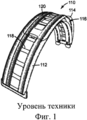
В респираторах PAPR в виде шлема часто используют поддерживаемый фильтрующий пакет для фильтрации воздуха до его поступления во внутреннее газовое пространство для дыхания. Держатели фильтрующего пакета иногда вообще не имеют опоры, или имеют ограниченную опору, проходящую через центр фильтрующего пакета, поскольку самого воздушного потока достаточно для поддержания слоев фильтра разделенными. ФИГ. 1 показывает опору фильтра, используемого в некоторых встраиваемых в шлем респираторах. Держатель ПО фильтрующего пакета выполнен с возможностью поддерживания плоского фильтрующего пакета в дугообразной форме для прилегания внутри куполообразного пространства шлема. Держатель 110 выполнен из двух элементов 112 и 114, где меньший элемент 114 поддерживается в сжатом состоянии для обеспечения отверстия 116 между двумя элементами у одного из его концов. Оба элемента 112 и 114 содержат множество отверстий 118 и 120, соответственно, которые выровнены вдоль длины держателя ПО. Держатель ПО фильтрующего пакета предусмотрен, прежде всего, для поддержания дугообразной формы фильтрующего пакета. Пример встроенной в шлем системы респираторов PAPR раскрыт в патенте США 4,280,491 (Berg et al.).Helmet-shaped PAPR respirators often use a supported filter bag to filter the air before it enters the breathing gas. The filter bag holders sometimes have no support at all, or have a limited support passing through the center of the filter bag, since the air flow itself is sufficient to keep the filter layers separated. FIG. 1 shows the filter support used in some helmet-mounted respirators. The holder of the filter bag software is configured to support the flat filter bag in an arc shape to fit inside the domed space of the helmet. The
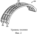
Еще один продукт, поддерживающий дугообразную форму фильтрующего пакета, раскрыт в патенте США 6,279,570 (Mittelstadt et al.). Как показано на ФИГ. 2, эта опора 200 фильтра имеет ребра 210 и 220, которые в целом выровнены с продольной осью устройства. Некоторые из этих опорных ребер 210 смещены в сторону от смежных ребер 220. ФИГ. 3 показывает, как фильтрующий пакет 310 может быть расположен вокруг опоры 200 в шлеме 300.Another product supporting the arcuate shape of the filter bag is disclosed in US Pat. No. 6,279,570 (Mittelstadt et al.). As shown in FIG. 2, this
Еще один респиратор PAPR описан в международной публикации WO 2011/126884 (Ausen). В этом устройстве, воздуходувное устройство помещено внутрь шлема вместе с фильтрующей средой и полостью, которая подает воздух из среды к фильтру. Воздух, который покидает фильтрующую среду, затем проходит в другую полость, где он выталкивается в конструкцию воздуходувного устройства, расположенную по центру внутри шлема. После прохождения через конструкцию воздуходувного устройства, отфильтрованный воздух затем подается пользователю через отверстие для отфильтрованного воздуха и канал для отфильтрованного воздуха.Another PAPR respirator is described in international publication WO 2011/126884 (Ausen). In this device, a blower device is placed inside the helmet along with a filter medium and a cavity that delivers air from the medium to the filter. The air that leaves the filter medium then passes into another cavity, where it is pushed into the structure of the blower device, located centrally inside the helmet. After passing through the design of the blower device, the filtered air is then supplied to the user through the filtered air hole and the filtered air channel.
Несмотря на то, что эти традиционные устройства для фильтрации обеспечивают хорошую опору для фильтрующего материала и проявляют хорошую фильтрацию проходящего через устройство воздуха, эти устройства не позволяют получить регулируемый воздушный поток, проходящий через фильтрующую среду. Без такого регулируемого или контролируемого потока, некоторые участки фильтрующей среды могут расходоваться раньше других, приводя к более быстрому сокращению срока службы.Although these conventional filtration devices provide good support for the filter material and exhibit good filtration of the air passing through the device, these devices do not allow an adjustable air flow passing through the filter medium. Without such a controlled or controlled flow, some sections of the filter medium may be consumed earlier than others, resulting in a faster reduction in service life.
СУЩНОСТЬ ИЗОБРЕТЕНИЯSUMMARY OF THE INVENTION
Настоящее изобретение предоставляет новый фильтрующий картридж, содержащий корпус, впускное отверстие, первую или расположенную выше по потоку систему распределения воздуха, вторую или расположенную ниже по потоку систему распределения воздуха и выпускное отверстие. Корпус содержит множество подсекций, при этом каждая из подсекций предусмотрена или сконструирована для вмещения фильтрующего элемента. Впускное отверстие расположено в первом участке корпуса. Расположенная выше по потоку система распределения воздуха находится в связи по текучей среде с впускным отверстием и с каждой из подсекций. Расположенная ниже по потоку система распределения воздуха находится в связи по текучей среде с каждой из подсекций, и выпускное отверстие находится в связи по текучей среде с нижней системой распределения воздуха. Первая и/или вторая из систем распределения воздуха сконструированы для обеспечения одинаковой скорости воздушного потока, проходящего через каждую подсекцию корпуса.The present invention provides a new filter cartridge comprising a housing, an inlet, a first or upstream air distribution system, a second or upstream air distribution system, and an outlet. The housing contains many subsections, with each of the subsections provided or designed to accommodate the filter element. The inlet is located in the first portion of the housing. The upstream air distribution system is in fluid communication with the inlet and with each of the subsections. The downstream air distribution system is in fluid communication with each of the subsections, and the outlet is in fluid communication with the lower air distribution system. The first and / or second of the air distribution systems are designed to provide the same speed of air flow passing through each subsection of the housing.
Преимущество настоящего изобретения заключается в том, что срок службы фильтра может быть продлен, поскольку каждая подсекция принимает воздушный поток одинаковой скорости. На каждый фильтрующий элемент может приходиться одинаковый объем воздушного потока и загрязняющих веществ, что не допускает окончания срока службы одного фильтрующего элемента значительно раньше других. Общий срок службы продукта может быть продлен. Сопротивление потоку всего фильтра также может быть сведено к минимуму, поскольку воздушный поток может проходить через все фильтрующие материалы одинаково, увеличивая, таким образом, количество задействованной фильтрующей средой по сравнению с фильтром с системами распределения воздушного потока, в которых весь воздух проталкивается через небольшой участок всей фильтрующей среды.An advantage of the present invention is that the filter life can be extended since each subsection receives an air flow of the same speed. Each filter element can have the same volume of air flow and pollutants, which prevents the end of the service life of one filter element much earlier than others. The total product life may be extended. The flow resistance of the entire filter can also be minimized, since the air flow can pass through all the filter materials equally, thus increasing the amount of filter medium used compared to a filter with air distribution systems in which all air is pushed through a small portion of the entire filter medium.
ГлоссарийGlossary
Используемые далее термины имеют следующие значения:The terms used below have the following meanings:
термин "активные микрочастицы" означает частицы или гранулы, специально предназначенные для выполнения некоторого действия или функции, такой как поглощение (адсорбция и/или абсорбция),катализ и ионный обмен;the term "active microparticles" means particles or granules specifically designed to perform some action or function, such as absorption (adsorption and / or absorption), catalysis and ion exchange;
термин "система распределения воздуха" означает деталь или комбинацию деталей, участвующих в регулировании воздушного потока;the term "air distribution system" means a part or a combination of parts involved in the regulation of air flow;
термин "воздушный поток" означает движение воздуха, большее, чем незначительное или неизмеримое;the term "air flow" means the movement of air greater than slight or immeasurable;
термин "скорость воздушного потока" означает давление, оказываемое движущимся воздухом, относительно исходного давления;the term "air flow rate" means the pressure exerted by moving air relative to the initial pressure;
термин "давление отсчета" означает давление, измеренное при давлении окружающей среды, или в месте, где существуют воздушные потоки, направленные в место, где измеряют давление, или из него;the term "reference pressure" means the pressure measured at ambient pressure, or in a place where there are air currents directed to the place where the pressure is measured, or from it;
термин "чистый воздух" означает воздух из окружающей атмосферы, который был отфильтрован для удаления загрязняющих веществ;the term "clean air" means air from the surrounding atmosphere that has been filtered to remove pollutants;
термин "загрязняющие вещества" означает частицы (включая пыль, аэрозоли и дым) и/или другие вещества, которые обычно могут не рассматриваться как частицы (например, органические испарения и т.д.), но которые могут быть взвешены в окружающем воздухе;the term “pollutants” means particles (including dust, aerosols and smoke) and / or other substances that may not normally be considered particles (eg, organic fumes, etc.), but which can be suspended in ambient air;
термин "куполообразное пространство" означает пространство между головой пользователя и внутренней стороной шлема;the term "domed space" means the space between the user's head and the inside of the helmet;
термин "расположенный ниже по потоку" означает «расположенный в более поздней точке во времени в воздушном потоке относительно соответствующей ему исходной точки»;the term “downstream” means “located at a later point in time in the air flow relative to its corresponding starting point”;
термин "выдыхаемый воздух" означает воздух, выдыхаемый человеком;the term "exhaled air" means air exhaled by a person;
термин "устройство для фильтрации" означает устройство, выполненное с возможностью удаления загрязняющих веществ из воздуха;the term "filtering device" means a device configured to remove contaminants from the air;
термин "фильтрующая среда" или "фильтрующий элемент" означает воздухопроницаемый материал, предназначенный для удаления загрязняющих веществ из воздуха, проходящего через него;the term "filter medium" or "filter element" means a breathable material designed to remove contaminants from the air passing through it;
термин "впускное отверстие для текучей среды" означает область, поверхность или объем пространства, через которое может входить воздух;the term "fluid inlet" means an area, surface or volume of space through which air may enter;
термин "фильтрующий слой" означает воздухопроницаемую структуру, содержащую один или несколько слоев и сконструированную для удаления загрязняющих веществ из воздуха, проходящего через нее;the term "filter layer" means an air-permeable structure containing one or more layers and designed to remove contaminants from the air passing through it;
термин "выпускное отверстие для текучей среды" означает область или участок, через который может выходить воздух;the term "fluid outlet" means a region or section through which air may exit;
термин "класс НЕРА" и "класс высокоэффективного воздушного фильтра", определяют эксплуатационные качества фильтрующего материала согласно указанным в разделе 42 Свода Федеральных Правил C.F.R. §84 (1995);the terms "HEPA class" and "high-performance air filter class" determine the performance of the filter material as specified in
термин "шлем" означает устройство, выполненное для ношения на голове человеком в целях защиты головы от вредного воздействия;the term "helmet" means a device made to be worn on the head by a person in order to protect the head from harmful effects;
термин "корпус" означает конструкцию или комбинацию деталей, предназначенную для полного или частичного вмещения или содержания другого объекта;the term "housing" means a structure or combination of parts designed to fully or partially contain or contain another object;
термин "внутреннее газовое пространство" означает пространство перед лицом человека, из которого возможно вдыхать чистый воздух;the term "internal gas space" means a space in front of a person from which it is possible to breathe clean air;
термин "продольная ось" означает ось, проходящую главным образом вдоль длины устройства для фильтрации;the term "longitudinal axis" means an axis extending mainly along the length of the filtering device;
термин "распределительный канал" означает два или более каналов или проходов, распределяющих воздух в направлении полости или из нее;the term "distribution channel" means two or more channels or passages that distribute air in or out of the cavity;
термин "полость" означает общий объем или пространство, в которое попадает воздух из более чем одного места, или из которого воздух попадает в более чем одно место;the term “cavity” means the total volume or space into which air enters from more than one place, or from which air enters more than one place;
термин "электроприводной воздухоочистительный респиратор" или "PAPR" означает устройство, способное подавать чистый воздух пользователю, в котором воздух фильтруется на пользователе посредством использования энергии не пользователя, а другого источника;the term “electric drive air cleaning respirator” or “PAPR” means a device capable of delivering clean air to a user, in which air is filtered on the user by using not a user energy, but a different source;
термин "в значительной степени одинаковый" означает соответствие одного другому с разницей в пределах 10%;the term "substantially the same" means the correspondence of one to the other with a difference of 10%;
термин "поперечная ось" означает ось, проходящую главным образом перпендикулярно продольной оси; иthe term "transverse axis" means an axis extending mainly perpendicular to the longitudinal axis; and
термин "расположенный выше по потоку" означает «расположенный в более ранней точке во времени в воздушном потоке относительно соответствующей ему исходной точки».the term “located upstream” means “located at an earlier point in time in the air flow relative to its corresponding starting point”.
КРАТКОЕ ОПИСАНИЕ ЧЕРТЕЖЕЙBRIEF DESCRIPTION OF THE DRAWINGS
ФИГ. 1 - вид в перспективе опоры ПО фильтра, известного из уровня техники, применяемого во встроенном в шлем респираторе.FIG. 1 is a perspective view of a software filter support known from the prior art used in a respirator integrated in a helmet.
ФИГ. 2 - вид в перспективе известного устройства 200 для поддержания дугообразной формы известного фильтрующего пакета.FIG. 2 is a perspective view of a known
ФИГ. 3 - вид сбоку известного из уровня техники устройства 200 для фильтрации, расположенного в пределах шлема 300.FIG. 3 is a side view of a prior
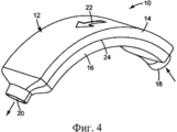
ФИГ. 4 - вид в перспективе устройства 10 для фильтрации согласно настоящему изобретению.FIG. 4 is a perspective view of a
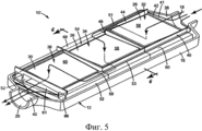
ФИГ. 5 - вид в перспективе устройства 10′ для фильтрации с удаленной верхней половиной 14 корпуса 12.FIG. 5 is a perspective view of a
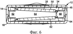
ФИГ. 6 - вид в поперечном сечении устройства 10′ для фильтрации, выполненном вдоль линий 6-6 согласно ФИГ. 5.FIG. 6 is a cross-sectional view of a
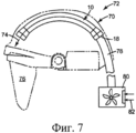
ФИГ. 7 - вид сбоку устройства 10 для фильтрации, расположенного в шлеме 70.FIG. 7 is a side view of the
ФИГ. 8 - вид в перспективе устройства 10′ для фильтрации, имеющего расположенные на нем каналы 90-96 для измерения давления в различных подсекциях устройства 10′ для фильтрации.FIG. 8 is a perspective view of a
ПОДРОБНОЕ ОПИСАНИЕ ИЗОБРЕТЕНИЯDETAILED DESCRIPTION OF THE INVENTION
В практической реализации настоящего изобретения предлагается устройство для фильтрации, содержащее корпус, впускное отверстие, первую систему распределения воздуха, вторую систему распределения воздуха, и выпускное отверстие. Корпус содержит множество подсекций, при этом каждая подсекция предназначена для вмещения по меньшей мере одного фильтрующего элемента. Впускное отверстие расположено в первом участке корпуса. Первая система распределения воздуха находится в связи по текучей среде с впускным отверстием и с каждой из подсекций. Вторая система распределения воздуха находится в связи по текучей среде с каждой из подсекций. Выпускное отверстие находится в связи по текучей среде со второй системой распределения воздуха. Первая и/или вторая система распределения воздуха сконструированы для обеспечения по сути одинаковой скорости воздушного потока, проходящего через каждую подсекцию. Это может быть достигнуто путем предусмотрения одной или нескольких полостей, одного или нескольких распределительных каналов, и/или каналов (ведущих в подсекции или из них), образующих одну или несколько систем распределения воздуха для обеспечения по сути одинаковой скорости воздушного потока. Если перепад давления в подсекции слишком мал, например, каналы или проходы, ведущие в эту подсекцию, могут быть увеличены, с одновременным увеличением поперечного сечения канала, ведущего в подсекцию или из нее. Если перепад давления слишком велик, может быть выполнено обратное действие для снижения перепада давления для достижения по сути одинаковой скорости воздушного потока.In a practical implementation of the present invention, there is provided a filtering device comprising a housing, an inlet, a first air distribution system, a second air distribution system, and an outlet. The housing contains many subsections, with each subsection designed to accommodate at least one filter element. The inlet is located in the first portion of the housing. The first air distribution system is in fluid communication with the inlet and with each of the subsections. A second air distribution system is in fluid communication with each of the subsections. The outlet is in fluid communication with a second air distribution system. The first and / or second air distribution system is designed to provide essentially the same speed of air flow passing through each subsection. This can be achieved by providing one or more cavities, one or more distribution channels, and / or channels (leading to or from the subsection), forming one or more air distribution systems to ensure substantially the same air velocity. If the pressure drop in the subsection is too small, for example, the channels or passages leading to this subsection can be increased, while the cross section of the channel leading to or from the subsection increases. If the pressure drop is too large, the opposite action can be taken to reduce the pressure drop to achieve essentially the same air velocity.
ФИГ. 4 показывает устройство для фильтрации, такое как фильтрующий картридж 10, который может быть использован в персональном устройстве для защиты органов дыхания, обеспечивающем пользователя чистым воздухом для дыхания. Устройство 10 для фильтрации содержит корпус 12, имеющий верхнюю часть или половину 14 и нижнюю часть или половину 16. Фильтруемый воздух входит в корпус 12 через впускное отверстие 18 и выходит из устройства через выпускное отверстие 20. Таким образом, воздух проходит через устройство в направлении стрелки 22. Воздух, входящий в устройство 10 через впускное отверстие 18, является неотфильтрованным, тогда как воздух, выходящий из устройства через выпускное отверстие 20, является отфильтрованным, то есть, он является чистым воздухом, безопасным для пользователя устройства для дыхания. По мере того, как воздух перемещается через внутреннюю часть корпуса, воздух проходит через один или несколько фильтрующих элементов, в которых загрязняющие вещества могут удаляться из воздушного потока. Корпус 12 может быть изогнутым в продольном направлении, как показано, то есть относительно поперечной оси, таким образом, чтобы устройство могло быть использовано в виде картриджа, расположенного в куполообразном пространстве шлема. Корпус 12 также может быть изогнут перпендикулярно продольному направлению или вдоль продольной оси или направления для дальнейшего образования куполообразного пространства в шлеме. Первая и вторая части 14 и 16 корпуса 12 соединены друг с другом по средней линии 24. Устройство может быть разделено вдоль линии 24 для замены фильтрующих элементов при необходимости.FIG. 4 shows a filtering device, such as a
Фиг. 5-6 показывают устройство для фильтрации не в изогнутой, а в плоской конфигурации. На этих фигурах верхняя часть 14 (ФИГ. 4) корпуса 12 удалена, таким образом, чтобы была видна внутренняя часть корпуса, а также фильтрующие элементы 26, 28, и 30, расположенные в подсекциях 32, 34, и 36, соответственно. Подсекции 32, 34, и 36 обеспечивают определенную область для фильтрующих элементов 26, 28, и 30 для их расположения внутри корпуса 12. Подсекции 32, 34, и 36 не находится в связи по текучей среде друг с другом. В дополнение к корпусу 12, устройство 10′ для фильтрации содержит впускное отверстие 18, первую полость 38, вторую полость 40, и выпускное отверстие 20. Первая полость 38 находится в связи по текучей среде с впускным отверстием 18 и с каждой из подсекций 32, 34 и 36. Вторая полость 40 также находится в связи по текучей среде с каждой из подсекций 32, 34 и 36. Выпускное отверстие 20 также находится в связи по текучей среде со второй полостью 40. Первая и вторая полости 38, 40 и связанные с ними воздушные распределительные каналы предусмотрены для обеспечения по сути одинаковой скорости воздушного потока, проходящего через каждую подсекцию 32, 34 и 36. Воздух, входящий в первую полость 38 из впускного отверстия 18, проходит в одном из трех различных направлений к одной из трех подсекций 32, 34 и 36. Воздух может перемещаться в первую подсекцию 32 через отверстие или канал 41 в подсекции 32 на первом конце 42. Отверстие в подсекции 32 ограничено на первом конце 42 боковыми стенками 44 и 46 подсекции и верхней половиной 14 (ФИГ. 4) корпуса 12. Воздух из окружающей среды, проходящий во второй и третий фильтрующие элементы 28 и 30, может проходить в верхние каналы 48 и 50, соответственно, как отмечено линиями 51 и 53 воздушного потока. Воздух, проходящий через отверстие 41 на первом конце 42 первой подсекции 32, проходит через стенку 56 первого фильтрующего элемента 26; воздух, проходящий через отверстие 54 второй подсекции 34, проходит через стенку 58 второго фильтрующего элемента 28; а воздух, проходящий через отверстие 59 третей подсекции 36,проходит через стенку 60 третьего фильтрующего элемента 30. Воздух, выходящий из второй и третей подсекций после фильтрации, проходит через проход 52 и отверстие 61, соответственно, для вхождения в полость 40.FIG. 5-6 show a filtering device not in a curved, but in a flat configuration. In these figures, the upper part 14 (FIG. 4) of the
ФИГ. 6 показывает, в частности, что каждая подсекция может содержать первый и второй фильтрующие элементы. Показанная третья подсекция 34, например, содержит расположенные друг напротив друга фильтрующие элементы 28 и 62. Воздух поступает в фильтрующий элемент 62 через нижний канал 64, таким же образом, как и воздух, поступающий в фильтрующий элемент 28 через верхний канал 48, как описано выше. Каждый фильтрующий элемент 28 и 62 наклонен относительно воздуха, входящего в подсекцию, способствуя лучшему прохождению воздуха через фильтрующие материалы. Воздух, проходящий через фильтрующие элементы 28 и 62, входит в полость 64 для того, чтобы затем выходить в проход 52,откуда он затем направляется через выходной канал 66 (ФИГ. 5) для вхождения в полость 40. Воздух в подсекции 32 (ФИГ. 5) подобным образом проходит через расположенные друг напротив друга фильтрующие элементы для входа в центральную полость, откуда он затем направляется в проход 68. Разделенный воздушный поток может быть получен, как описано в заявке на патент США Split Flow Filtering Device (USSN 13/310, 881) (Billingsley et a)l. Несмотря на то, что устройство для фильтрации согласно настоящему изобретению показано имеющим три подсекции, устройство может быть выполнено имеющим 2, 3, 4, 5 и до 10, 20 или более подсекций. Скорости воздушного потока, проходящего через каждую подсекцию, в значительной степени одинаковы, предпочтительно, отличаются не более, чем на приблизительно 5% относительно любой из них.FIG. 6 shows, in particular, that each subsection may comprise first and second filter elements. The
ФИГ. 7 показывает пример изогнутого устройства 10 для фильтрации согласно настоящему изобретению, используемого в куполообразном пространстве шлема 70 респиратора PAPR 72. Чистый воздух 74, выходящий из устройства 10 для фильтрации, входит во внутреннее газовое пространство 76 шлема 70, где его может вдыхать пользователь. Атмосферный воздух подается во впускное отверстие 18 для текучей среды устройства 10 через канал 78. Воздуходувное устройство 80 нагнетает или втягивает неотфильтрованный воздух 82 через канал 78 в устройство 10 для фильтрации согласно изобретению. Воздуходувное устройство 80 может быть эффективно запитано от подходящего источника питания, такого как батарея, которая может быть пассивированной - см.патент США 7,947,109 (Sayers et al.). Воздуходувное устройство 80 может быть расположено на ремне, надеваемом на пользователя. Оно также может быть изолировано от окружающей среды - см. патент США 6,796,304 (Odell et al.); см. также патент США 6,823,867 (Avery et al.). Воздушный поток также может быть откалиброван в системе респиратора - см. патент США 6,666,209 (Bennett et al.), или обработан иным способом - см. патент США 7,197,774 (Curran et al.). Для предупреждения пользователя о том, что воздушный поток уменьшается ниже преопределенного значения, может быть использован индикатор потока. Поскольку воздух проходит через множество подсекций, для фильтрации доступна большая площадь поверхности, снижая, таким образом, перепад давления в устройстве 10. Более низкий перепад давления означает, что для протягивания окружающего воздуха через фильтрующую среду требуется меньше энергии. Также дополнительная площадь поверхности может продлить срок службы фильтрующей среды, поскольку может потребоваться больше времени для забивания пор в материале различными загрязняющими веществами. Шлем может быть, например, защитным шлемом сварщика - см., например, патенты США 6,934,967 (Miyashita et al.) и 7,637,622 (Magnusson et al.) - с надеваемой на голову системой подвески (патент США 6,367,085 (Berg)). Изобретение также может быть использовано в устройстве со шлемом сварщика в виде колпака - см.патент США 7,104,264 (Lee et al.).FIG. 7 shows an example of a
Полости и распределительные каналы систем распределения воздуха могут определяться формой и конфигурацией корпуса и первой, второй и третьей подсекций.The cavities and distribution channels of the air distribution systems can be determined by the shape and configuration of the housing and the first, second and third subsections.
Полость может содержать физическую конструкцию, способствующую формированию конструкции всего устройства, и распределительные каналы могут содержать физическую конструкцию, используемую для образования каналов и проходов, способствующих разделению потока текучей среды на два или более потока по направлению к двум или более независимо функционирующим подсекциям, содержащим фильтрующую среду.The cavity may contain a physical structure that facilitates the construction of the entire device, and the distribution channels may contain a physical structure used to form channels and passages that facilitate the separation of the fluid stream into two or more streams in the direction of two or more independently functioning subsections containing the filter medium .
Корпус может быть выполнен из множества различных материалов и иметь множество различных форм. Примеры материалов, из которых может быть изготовлен корпус, включают пластмассы, металлы, спрессованные или связанные волокнистые композиционные структуры. В зависимости от используемых материалов и от желаемой конструкции получаемого в результате устройства, корпус может быть изготовлен посредством различных технологий, включая литье под давлением, вакуумное формование, вырубную штамповку, быстрое прототипирование, трехмерное управляемого компьютером изготовление, штамповку, экструзию в заготовку и отливку. Корпус также может быть продуктом на рулонной основе - см., например, заявку на патент США 12/784,182 (Billingsley et al.). Корпус и конструкция подсекций могут определять местоположение фильтрующих слоев относительно друг друга и конструкции в целом.The housing may be made of many different materials and have many different shapes. Examples of materials from which the housing can be made include plastics, metals, pressed or bonded fibrous composite structures. Depending on the materials used and the desired design of the resulting device, the casing can be manufactured using various technologies, including injection molding, vacuum molding, die stamping, rapid prototyping, three-dimensional computer-controlled manufacturing, stamping, extrusion into the workpiece and casting. The housing may also be a roll-based product — see, for example,
Фильтрующие элементы, используемые совместно с настоящим изобретением, могут содержать один или несколько слоев фильтрующих материалов для задержания частиц и/или газообразных веществ. Материалы фильтра для задержания частиц предназначены для удаления частиц, взвешенных в окружающем воздухе, а материалы для задержания газообразных веществ предназначены для удаления взвешенных в нем испарений. Фильтрующие слои могут иметь различную форму и конфигурацию, и для целей респиратора могут иметь толщину от приблизительно 0,2 миллиметров (мм) до двух сантиметров (см), или от 0,5 до 1,5 см, или это может быть в целом плоский фильтр, или он может быть гофрированным для обеспечения увеличенной площади поверхности - см., например, патенты США 5,804,295 и 5,656,368 (Braun et al.). Каждый фильтрующий слой также может содержать множество фильтрующих слоев, соединенных друг с другом посредством адгезива или любых других средств. Фильтрующие слои также могут содержать параллельные каналы, как описано, например, в патентах США 6,752,889 и 6,280,824 (Insley et al.). Фильтрующая среда также могут быть фильтрами класса НЕРА. По сути, любой известный подходящий материал (или разработанный позже) для формирования фильтрующего слоя может быть использован в качестве фильтрующего материала. Полотна из волокон, выполненных по технологии мелтблаун, такие, как описанные в Wente, Van А., Superfine Thermoplastic Fibers, Indus. Engn. Chem., 48, 1342 et seq. (1956), особенно квазипостоянно электрически заряженной (электретной) формы, являются особенно подходящими (см., например, патент США №4,215,682 (Kubik et al.)). Эти волокна, выполненные по технологии мелтблаун, могут быть микроволокнами с эффективным диаметром менее приблизительно 20 микрометров (мкм) (именуемые BMF как сокращение от "blown microfiber"). Эффективный диаметр волокна может быть определен согласно Davies, С.N.,. The Separation Of Airborne Dust Particles, Institution Of Mechanical Engineers, London, Proceedings 1B, 1952. Широко используются полотна BMF, содержащие волокна, образованные из полипропилена, поли(4-метил-1-пентена) и их сочетаний. Электрически заряженные фибриллированные волокна, согласно патенту США RE 31,285 (van Turnhout), также могут быть пригодными, также как и полотна из волокон древесной шерсти и стеклянных волокон или волокон, полученных путем раздува из раствора, или электростатически распыленных волокон, особенно в форме микроволокон. Электрический заряд может быть сообщен волокнам путем контакта волокон с водой, как описано в патентах США 6,824,718 (Eitzman et al.), 6,783,574 (Angadjivand et al.), 6,743,464 (Insley e tel.), 6,454,986 и 6,406,657 (Eitzman et al.), и 6,375,886 и 5,496,507 (Angadjivand et al.)/ Электрический заряд также может быть сообщен волокнам коронным разрядом, как описано в патенте США 4,588,537 (Klasse et а1.),или трибоэлектризацией, как описано в патенте США 4,798,850 (Brown). Также в волокна могут быть включены добавки для усиления эффекта фильтрации полотен, изготовленных в процессе гидрозарядки (см. патент США 5,908, (Rousseau et al.)). В частности, на поверхности волокон в фильтрующем слое для усиления эффекта фильтрации в условиях жиросодержащего тумана могут быть расположены атомы фтора, - см. патенты США 6,398,847 В1, 6,397,458 В1, и 6,409,806 B1 (Jones et al.). Типичный сухой вес для фильтрующих слоев из электрета BMF составляет приблизительно от 10 до 100 грамм на квадратный метр. Набивки фильтра из активных частиц также могут быть использованы, как и проницаемые сформированные структуры из активных частиц, собранных, например, посредством микрочастиц полисиаловой кислоты - см.патент США 6,391,429 (Senkus et a.l).- или связанных частиц сорбирующего вещества, как описано в патенте США 5,033,465 (Braun et al.).The filter elements used in conjunction with the present invention may contain one or more layers of filter materials to trap particles and / or gaseous substances. Filter materials for trapping particles are designed to remove particles suspended in ambient air, and materials for trapping gaseous substances are designed to remove suspended vapors in it. The filter layers can have a different shape and configuration, and for respirator purposes, can have a thickness of from about 0.2 millimeters (mm) to two centimeters (cm), or from 0.5 to 1.5 cm, or it can be generally flat filter, or it may be pleated to provide increased surface area — see, for example, US Pat. Nos. 5,804,295 and 5,656,368 (Braun et al.). Each filter layer may also contain a plurality of filter layers connected to each other by adhesive or any other means. The filter layers may also contain parallel channels, as described, for example, in US patents 6,752,889 and 6,280,824 (Insley et al.). Filter media can also be HEPA filters. In fact, any known suitable material (or developed later) for forming a filter layer can be used as a filter material. Meltblown fiber webs, such as those described in Wente, Van A., Superfine Thermoplastic Fibers, Indus. Engn. Chem., 48, 1342 et seq. (1956), especially quasi-permanently electrically charged (electret) forms, are particularly suitable (see, for example, US patent No. 4,215,682 (Kubik et al.)). These meltblown fibers can be microfibers with an effective diameter of less than about 20 micrometers (microns) (referred to as BMF as short for "blown microfiber"). Effective fiber diameter can be determined according to Davies, C.N.,. The Separation Of Airborne Dust Particles, Institution Of Mechanical Engineers, London, Proceedings 1B, 1952. BMF fabrics are widely used containing fibers formed from polypropylene, poly (4-methyl-1-pentene), and combinations thereof. Electrically charged fibrillated fibers according to US patent RE 31,285 (van Turnhout) may also be suitable, as well as webs of wood wool and glass fibers or fibers obtained by blowing from a solution, or electrostatically sprayed fibers, especially in the form of microfibers. An electric charge can be imparted to the fibers by contacting the fibers with water, as described in US Pat. Nos. 6,824,718 (Eitzman et al.), 6,783,574 (Angadjivand et al.), 6,743,464 (Insley e tel.), 6,454,986 and 6,406,657 (Eitzman et al.) , and 6,375,886 and 5,496,507 (Angadjivand et al.) / The electric charge can also be imparted to the fibers by corona discharge, as described in US Pat. No. 4,588,537 (Klasse et al.), or triboelectrification, as described in US Pat. No. 4,798,850 (Brown). Also, additives can be included in the fibers to enhance the filtering effect of the webs made during the hydrocharging process (see US Pat. No. 5,908, (Rousseau et al.)). In particular, fluorine atoms may be located on the surface of the fibers in the filter layer to enhance the filtering effect under a greasy mist — see U.S. Patents 6,398,847 B1, 6,397,458 B1, and 6,409,806 B1 (Jones et al.). Typical dry weights for BMF electret filter media are approximately 10 to 100 grams per square meter. Filter packs of active particles can also be used, as well as permeable formed structures of active particles collected, for example, by polysialic acid microparticles - see US Patent 6,391,429 (Senkus et al) .- or bound particles of a sorbent substance, as described in the patent U.S. 5,033,465 (Braun et al.).
Пример волокнистой основы, содержащей активные частицы, показан в заявке на патент США №. 2005/0169820А1. Частицы сорбирующего вещества могут быть включены в полотно, обычно так, чтобы в полотно было включено по меньшей мере приблизительно 60 процентов по весу частиц сорбирующего вещества. Волокна, используемые в содержащем частицы полотне, обычно имеют относительно более высокую усадку при кристаллизации, чем у аналогичных волокон. Волокна обычно содержат полипропилен, и частицы сорбирующего вещества обычно равномерно распределены в полотне, таким образом, чтобы полотно имело уровень поглощения А по меньшей мере 1,6×10⁴/миллиметров (мм) воды. Пористым листовым изделиям обычно свойственен низкий перепад давления, долгий срок службы и уровень поглощения А, превышающий уровень поглощения угля в набивке фильтра. Уровень поглощения А может быть вычислен с использованием параметров или измерений подобно тому, как описано в Wood, Journal of the American Industrial Hygiene Association, 55(1), 11-15 (1994). Дополнительную информацию об уровне поглощения А можно найти в заявке на патент США, приведенной выше в данном абзаце. Активные частицы, которые могут быть использованы в фильтрах настоящего изобретения, включают частицы или гранулы, подходящие для выполнения некоторых действий или функций, связанных с определенными характеристиками или свойствами, включает свойства химического превращения, такого как реакция, катализ, ионный обмен, и/или физические свойства, такие как обширная площадь поверхности, пористость, относительно малый размер и форма. Одним примером активных частиц являются частицы, взаимодействующие с компонентами в текучей среде для их удаления или изменения их состава. Компоненты в текучей среде могут поглощаться на поверхности активных частиц или внутрь них, или они могут вступать в реакцию для образования более безвредного соединения. Соответственно, активные частицы могут обладать сорбирующим свойством, катализирующим свойством или могут вступать в реакции для образования более безвредного соединения. Примеры содержащих частицы материалов, которые могут быть использованы совместно с настоящим изобретением, включают гранулы сорбирующих микрочастиц, таких как активированный уголь, активированный уголь с химически обработанной поверхностью, оксид алюминия, силикагель, бентонит, каолиновый диатомит, порошковые цеолиты (как натуральные, так и синтетические), ионообменные смолы и молекулярные фильтры, и частицы, такие как каталитические частицы и частицы, содержащие заключенные в оболочку соединения. Стандартные активные частицы включают частицы активированного угля, химически обработанного угля, и оксида алюминия. Примеры коммерчески доступного активированного угля, который может быть использован в настоящем изобретении, включают Кигагау 12×20 типа GG (от изготовителя Kuraray Chemical Corporation, Осака, Япония) и Calgon 12×30 URC от изготовителя Calgon Carbon Corporation, Питтсбург, Пенсильвания. Патенты, описывающие различные типы активных частиц, которые могут быть использованы в настоящем изобретении, включают патенты США 7,309,513 (Brey et al.), 7,004,990 и 6,391,429 Senkus et al., 6,767,860 (Hern et al), 5,763,078 Braun et al, и 5,496,785 (Abler).An example of a fibrous base containing active particles is shown in US Patent Application No. 2005 / 0169820A1. Particles of the sorbent substance can be included in the canvas, usually so that at least about 60 percent by weight of the particles of the sorbent substance is included in the canvas. The fibers used in the particle-containing web typically have a relatively higher shrinkage during crystallization than similar fibers. The fibers typically contain polypropylene, and the sorbent particles are usually evenly distributed in the fabric, so that the fabric has an absorption level A of at least 1.6 × 10 4 / millimeters (mm) of water. Porous sheet products are typically characterized by a low pressure drop, a long service life and an absorption level A that exceeds the absorption level of coal in the filter pack. Absorption rate A can be calculated using parameters or measurements similar to that described in Wood, Journal of the American Industrial Hygiene Association, 55 (1), 11-15 (1994). Further information on Absorption Rate A can be found in the US patent application cited above in this paragraph. Active particles that can be used in the filters of the present invention include particles or granules suitable for performing certain actions or functions associated with certain characteristics or properties, including chemical conversion properties such as reaction, catalysis, ion exchange, and / or physical properties such as extensive surface area, porosity, relatively small size and shape. One example of active particles are particles that interact with components in a fluid to remove or change their composition. Components in the fluid can be absorbed on the surface of the active particles or inside them, or they can react to form a more harmless compound. Accordingly, the active particles may have a sorbing property, a catalyzing property, or may react to form a more harmless compound. Examples of particle-containing materials that can be used with the present invention include sorbent microparticle granules such as activated carbon, chemically treated activated carbon, alumina, silica gel, bentonite, kaolin diatomite, powder zeolites (both natural and synthetic ), ion exchange resins and molecular filters, and particles, such as catalytic particles and particles containing enclosed compounds. Standard active particles include particles of activated carbon, chemically treated carbon, and alumina. Examples of commercially available activated carbon that can be used in the present invention include Kigagau 12 × 20 type GG (from manufacturer Kuraray Chemical Corporation, Osaka, Japan) and
Несмотря на то, что изобретение было описано и проиллюстрировано для использования совместно с персональными устройствами для защиты органов дыхания, такими как сварные шлемы и респираторы PAPR, изобретение также может быть использовано в системе коллективной защиты и в сооружениях, таких как здания и палатки. В таки случая множество отрегулированных устройств для фильтрации - или штабелей из таких устройств - может быть использовано для фильтрации воздуха перед его поступлением в здания или сооружения; см., например, патент США 7,995,570 (Insley et al.).Although the invention has been described and illustrated for use in conjunction with personal respiratory protection devices such as welded helmets and PAPR respirators, the invention can also be used in a collective protection system and in facilities such as buildings and tents. In this case, however, many adjusted filtration devices — or stacks of such devices — can be used to filter air before it enters buildings or structures; see, for example, US Pat. No. 7,995,570 (Insley et al.).
ПРИМЕРEXAMPLE
Испытание воздушного потокаAirflow test
Для подтверждения того, что скорости воздушного потока, проходящего через подсекции фильтров, в значительной степени одинаковы, измеряют разницу между давлением воздуха в подсекциях фильтров и окружающем воздухе. Если давление окружающего воздуха не используется, за давления или давления, используемого в качестве основы для сравнения, должна приниматься скорость воздуха, проходящего через весь фильтр, а не через ряд подсекций. Измерения давления могут быть выполнены без фильтрующей среды в подсекциях или с фильтрующей средой в подсекциях. Если фильтрующая среда во время измерения находится в подсекциях, используемая фильтрующая среда должна быть по сути одинаковой в каждой из подсекций, присущих изобретению. Каналы для измерения давления в подсекциях, в которых давление не измеряют, должны быть перекрыты. Записывают разницу значений между исходной величиной и величиной в каждой из подсекций.To confirm that the speeds of the air flow passing through the filter subsections are substantially the same, the difference between the air pressure in the filter subsections and the ambient air is measured. If ambient air pressure is not used, the pressure or pressure used as the basis for comparison should be taken as the speed of air passing through the entire filter, and not through a series of subsections. Pressure measurements can be performed without a filter medium in subsections or with a filter medium in subsections. If the filter medium is in subsections during the measurement, the filter medium used should be essentially the same in each of the subsections inherent in the invention. Channels for measuring pressure in subsections in which pressure is not measured should be closed. The difference between the original value and the value in each of the subsections is recorded.
Конструкция воздушного фильтраAir filter design
Был сконструирован и выполнен корпус фильтра, содержащий шесть фильтрующих элементов, расположенных в трех подсекциях, подобным образом, как в устройстве для фильтрации, показанном и описанном со ссылкой на ФИГ. 5-6. Системы распределения воздуха для каждой из трех подсекций были сконструированы таким образом, чтобы в каждой подсекции был одинаковый поток воздуха, направленный в нее и из нее. В каждой из трех подсекций были расположены, соответственно, каналы 90, 92 и 94 для измерения давления, а также был выполнен канал 96, расположенный на выпускном отверстии полости фильтра, как показано на ФИГ. 8. Посредством канала 96 измеряли исходное давление. Используемые в каждой из подсекций фильтрующие элементы содержали фильтрующую среду в виде частиц, и полотно, содержащее уголь для фильтрации газообразных загрязняющих веществ. Была использована фильтрующая среда, как описанные в заявке на патент США 2005/0169820 A1 (Tatarchuk et al.). Эта фильтрующая среда имеет измеряемое сопротивление воздушному потоку и содержит активные частицы, захваченные внутри основы из микроволокон.A filter housing was designed and constructed, comprising six filter elements arranged in three subsections, similarly to the filtering device shown and described with reference to FIG. 5-6. The air distribution systems for each of the three subsections were designed so that each subsection had the same air flow directed into and out of it. In each of the three subsections,
Воздух со скоростью двадцать пять литров в минуту пропускали через корпус 12 фильтра. Ручное устройство Extech 755 было использовано для измерения разницы давления между выпускным отверстием 96 и каждой из подсекций 90-94 согласно Испытанию воздушного потока. Измерения давления для трех подсекций приведены ниже в Таблице 1:Air at a speed of twenty-five liters per minute was passed through the
Данные в Таблице 1 показывают, что измеренное давление в каждой фильтрующей подсекции одинаково с другими подсекциями. Относительная скорость воздушного потока через каждую из трех подсекций в устройстве для фильтрации, таким образом, в значительной степени одинакова. С одинаковыми скоростями воздушного потока ожидается, что преимуществом устройства для фильтрации будет продленный срок службы.The data in Table 1 show that the measured pressure in each filter subsection is the same as the other subsections. The relative speed of the air flow through each of the three subsections in the filtering device is thus substantially the same. With the same air flow rates, it is expected that the advantage of the filtering device is an extended service life.
Данное изобретение допускает различные модификации и изменения, не выходящие за рамки его объема и сути. Следовательно, данное изобретение не ограничивается вышеописанным, и определяется ограничениями, заявленными в пунктах формулы и любыми их эквивалентами.This invention allows various modifications and changes, not going beyond its scope and essence. Therefore, this invention is not limited to the above, and is determined by the limitations claimed in the claims and any equivalents thereof.
Данное изобретение может быть также реализовано на практике при отсутствии любого элемента, отдельным образом не раскрытого в настоящей заявке.This invention can also be practiced in the absence of any element not specifically disclosed in this application.
Все вышеперечисленные патенты или патентные заявки, включая приведенные в разделе «Уровень техники», полностью включены в настоящий документ посредством ссылки. В случае противоречия или разночтения между раскрытием в таком включенном документе и вышеприведенным описанием, вышеприведенное описание должно иметь приоритетное значение.All of the above patents or patent applications, including those listed in the section "prior art", are fully incorporated herein by reference. In the event of a conflict or discrepancy between the disclosure in such an included document and the above description, the above description shall take precedence.
Claims (20)
(a) корпус, содержащий множество подсекций, при этом каждая подсекция выполнена с возможностью вмещения фильтрующего элемента;
(b) впускное отверстие, расположенное в первом участке корпуса;
(c) расположенную выше по потоку систему распределения воздуха, находящуюся в связи по текучей среде с впускным отверстием и с каждой из подсекций;
(d) расположенную ниже по потоку систему распределения воздуха, находящуюся в связи по текучей среде с каждой из подсекций; и
(е) выпускное отверстие, находящееся в связи по текучей среде с расположенной ниже по потоку системой распределения воздуха; при этом указанные расположенная выше или расположенная ниже по потоку системы распределения воздуха выполнены с возможностью обеспечения практически одинаковой скорости воздушного потока, проходящего через каждую подсекцию.1. A personal air filtration device for respiratory protection, comprising:
(a) a housing comprising a plurality of subsections, wherein each subsection is configured to receive a filter element;
(b) an inlet located in a first portion of the housing;
(c) an upstream air distribution system in fluid communication with the inlet and with each of the subsections;
(d) a downstream air distribution system in fluid communication with each of the subsections; and
(e) an outlet in fluid communication with the downstream air distribution system; wherein said upstream or downstream air distribution systems are configured to provide substantially the same speed of air flow passing through each subsection.
Applications Claiming Priority (3)
| Application Number | Priority Date | Filing Date | Title |
|---|---|---|---|
| US13/326,377 | 2011-12-15 | ||
| US13/326,377 US8887719B2 (en) | 2011-12-15 | 2011-12-15 | Air filtration device having tuned air distribution system |
| PCT/US2012/069090 WO2013090330A1 (en) | 2011-12-15 | 2012-12-12 | Air filtration device having tuned air distribution system |
Publications (1)
| Publication Number | Publication Date |
|---|---|
| RU2579344C1 true RU2579344C1 (en) | 2016-04-10 |
Family
ID=48608843
Family Applications (1)
| Application Number | Title | Priority Date | Filing Date |
|---|---|---|---|
| RU2014121152/12A RU2579344C1 (en) | 2011-12-15 | 2012-12-12 | Air filtration device with controlled air distribution system |
Country Status (9)
| Country | Link |
|---|---|
| US (2) | US8887719B2 (en) |
| EP (1) | EP2790793B1 (en) |
| JP (1) | JP6170505B2 (en) |
| KR (1) | KR102028775B1 (en) |
| CN (1) | CN103974747B (en) |
| AU (1) | AU2012352491B2 (en) |
| BR (1) | BR112014014101A2 (en) |
| RU (1) | RU2579344C1 (en) |
| WO (1) | WO2013090330A1 (en) |
Cited By (1)
| Publication number | Priority date | Publication date | Assignee | Title |
|---|---|---|---|---|
| RU2737910C2 (en) * | 2016-05-13 | 2020-12-04 | Дональдсон Компани, Инк. | Filtering materials, elements and methods |
Families Citing this family (32)
| Publication number | Priority date | Publication date | Assignee | Title |
|---|---|---|---|---|
| US8899227B2 (en) | 2011-12-15 | 2014-12-02 | 3M Innovative Properties Company | Air filtration device having subsections lacking fluid communication |
| US8887719B2 (en) | 2011-12-15 | 2014-11-18 | 3M Innovative Properties Company | Air filtration device having tuned air distribution system |
| US20130160195A1 (en) * | 2011-12-22 | 2013-06-27 | James Thomas Clement | Portable fan and battery box for clearing fog/particles in goggles or for cooling masks and helmets |
| WO2014040658A1 (en) | 2012-09-12 | 2014-03-20 | Camfil Ab | Backing net structure |
| WO2014194050A1 (en) * | 2013-05-30 | 2014-12-04 | Scott Technologies, Inc. | Pump panel accountability device and method of use |
| US11033433B2 (en) | 2014-06-16 | 2021-06-15 | Illinois Tool Works Inc | Removable shield for protective headwear |
| US10034510B2 (en) | 2014-06-16 | 2018-07-31 | Illinois Tool Works Inc. | Headgear for protective headwear |
| US9999546B2 (en) | 2014-06-16 | 2018-06-19 | Illinois Tool Works Inc. | Protective headwear with airflow |
| USD769535S1 (en) | 2015-05-12 | 2016-10-18 | Illinois Tool Works Inc. | Protective helmet |
| USD776360S1 (en) | 2015-05-12 | 2017-01-10 | Illinois Tool Works Inc. | Protective helmet |
| USD776359S1 (en) | 2015-05-12 | 2017-01-10 | Illinois Tool Works Inc. | Protective helmet |
| USD777987S1 (en) | 2015-05-12 | 2017-01-31 | Illinois Tool Works Inc. | Protective helmet |
| USD769543S1 (en) | 2015-05-12 | 2016-10-18 | Illinois Tool Works Inc. | Protective helmet |
| USD769542S1 (en) | 2015-05-12 | 2016-10-18 | Illinois Tool Works Inc. | Protective helmet |
| USD770689S1 (en) | 2015-05-12 | 2016-11-01 | Illinois Tool Works Inc. | Protective helmet |
| USD782120S1 (en) | 2015-05-12 | 2017-03-21 | Illinois Tool Works Inc. | Protective helmet |
| CN105435384B (en) * | 2015-12-11 | 2018-10-16 | 东莞市基一核材有限公司 | Stability air supply system |
| CN109068784B (en) * | 2016-01-07 | 2021-08-20 | Thi总医疗创新公司 | Wearable barrier system, apparatus and method with contactless control |
| KR101865203B1 (en) * | 2016-05-09 | 2018-06-07 | 경남엔지니어링(주) | Dust mask |
| USD779128S1 (en) | 2016-05-20 | 2017-02-14 | Illinois Tool Works Inc. | Protective helmet |
| USD781502S1 (en) | 2016-05-20 | 2017-03-14 | Illinois Tool Works Inc. | Protective helmet |
| CN106723586A (en) * | 2017-01-19 | 2017-05-31 | 王春山 | A kind of outdoor protector |
| US11812816B2 (en) * | 2017-05-11 | 2023-11-14 | Illinois Tool Works Inc. | Protective headwear with airflow |
| US11253022B2 (en) | 2017-09-22 | 2022-02-22 | 3M Innovative Properties Company | Protective headgear with adjustable air supply |
| US10653197B2 (en) * | 2018-03-23 | 2020-05-19 | Poma 22, Llc | Hard hat with filtered, battery-operated air flow system and method |
| CN109568821B (en) * | 2018-12-24 | 2021-05-04 | 上海纳米技术及应用国家工程研究中心有限公司 | Wearable air purifier for preventing allergy of dust mites |
| US12017232B2 (en) | 2020-03-13 | 2024-06-25 | Julian HENLEY | Electro-ionic mask devices for improved protection from airborne biopathogens |
| WO2021184012A1 (en) | 2020-03-13 | 2021-09-16 | Henley Julian | Electro-ionic devices for improved protection from airborne biopathogens |
| US11744914B2 (en) * | 2020-07-15 | 2023-09-05 | John R. Wyss | Projection of germicidal ultra-violet light by edgelit substrate |
| NL2026570B1 (en) * | 2020-09-29 | 2022-05-30 | New Nourishment Consultancy | Protective device for protecting a user of the device from inhaling air-borne pathogens from ambient air |
| KR102449970B1 (en) * | 2020-12-17 | 2022-10-05 | 국방과학연구소 | Adsorption filter structure or helmet with Adsorption filter structure |
| USD986510S1 (en) | 2021-05-11 | 2023-05-16 | Barbara D Leschinsky | Wearable air sterilizer with slidable face shield |
Citations (4)
| Publication number | Priority date | Publication date | Assignee | Title |
|---|---|---|---|---|
| US20050223902A1 (en) * | 2004-04-12 | 2005-10-13 | Lovell William S | Self-powered, wearable personal air purifier |
| US20060048782A1 (en) * | 2004-09-03 | 2006-03-09 | Safety Tech International, Inc. | Thin profile air purifying blower unit and filter cartridges, and method of use |
| WO2008153455A1 (en) * | 2007-05-30 | 2008-12-18 | Klas Jakobsson | Air cleaning system for one or several rooms and a filtration unit forming part of the air cleaning system |
| WO2011126884A2 (en) * | 2010-04-06 | 2011-10-13 | 3M Innovative Properties Company | Helmet-mounted respirator apparatus with a dual plenum system |
Family Cites Families (63)
| Publication number | Priority date | Publication date | Assignee | Title |
|---|---|---|---|---|
| US3621841A (en) | 1970-05-14 | 1971-11-23 | Mine Safety Appliances Co | Foldable protective head enclosure |
| IT1070735B (en) | 1976-10-04 | 1985-04-02 | Pirelli | IMPROVEMENTS IN HEAD PROTECTION AND RESPIRATORY TRACTOR DEVICES |
| GB2061696B (en) | 1979-10-30 | 1984-05-16 | Martindale Protection Ltd | Protective respiratory helmet |
| US4280491A (en) * | 1980-03-07 | 1981-07-28 | Minnesota Mining And Manufacturing Company | Powered air respirator |
| US4462399A (en) * | 1981-10-02 | 1984-07-31 | Minnesota Mining And Manufacturing Company | Powered air respirator and cartridge |
| US4501272A (en) | 1981-10-30 | 1985-02-26 | Shigematsu Works Co., Ltd. | Mask |
| USRE33118E (en) * | 1984-08-13 | 1989-11-28 | Arvin Industries, Inc. | Exhaust processor |
| GB2201601B (en) | 1987-03-06 | 1991-09-25 | Coal Ind | Improved helmet |
| US4886058A (en) | 1988-05-17 | 1989-12-12 | Minnesota Mining And Manufacturing Company | Filter element |
| GB8815179D0 (en) * | 1988-06-25 | 1988-08-03 | Racal Safety Ltd | Differential pressure sensor |
| US5283914A (en) * | 1990-12-20 | 1994-02-08 | Coal Industry (Patents) Limited | Protective helmets |
| USH1360H (en) | 1991-04-24 | 1994-10-04 | The United States Of America, As Represented By The Secretary Of The Army | Lightweight protective gas mask and hood |
| US5104430A (en) | 1991-06-11 | 1992-04-14 | Her Mou Lin | Mask with an air filtering device |
| US5533500A (en) | 1992-03-04 | 1996-07-09 | Her-Mou; Lin | Helmet with an air filtering device |
| DE69305173T2 (en) * | 1992-07-31 | 1997-05-22 | Mine Safety Appliances Co | BREATHING DEVICE FOR A HELMET |
| US5660173A (en) | 1993-12-30 | 1997-08-26 | The United States Of America As Represented By The Secretary Of The Army | Frustum layered canister |
| US5964221A (en) * | 1994-11-15 | 1999-10-12 | Gore Enterprise Holdings, Inc. | Rebreather adsorbent system |
| US5732695A (en) | 1997-03-11 | 1998-03-31 | Parmelee Industries | Respirator filtration device |
| US6176239B1 (en) | 1997-08-06 | 2001-01-23 | The United States Of America As Represented By The Secretary Of The Army | Advanced chemical-biological mask |
| US6014971A (en) | 1997-08-15 | 2000-01-18 | 3M Innovative Properties Company | Protective system for face and respiratory protection |
| US5992414A (en) | 1997-08-26 | 1999-11-30 | Mine Safety Appliances Company | Respirator filter |
| US6233748B1 (en) | 1998-07-31 | 2001-05-22 | Integrated Medical Systems, Inc. | Environmental protection system |
| US6345620B2 (en) | 1998-10-23 | 2002-02-12 | Mine Safety Appliances Company | Flexible respirator filter |
| DE19851322C1 (en) | 1998-11-06 | 2000-03-02 | Draeger Sicherheitstech Gmbh | Protective breathing mask has a clamping ring for simple fixing of a mask body onto a projecting housing edge with a range of connection geometries |
| US6367085B1 (en) | 1998-12-21 | 2002-04-09 | 3M Innovative Properties Company | Head suspension for an air supplied hood system |
| US6279570B1 (en) | 1999-03-02 | 2001-08-28 | 3M Innovative Properties Company | Filter support, assembly and system |
| US6467481B1 (en) | 1999-04-29 | 2002-10-22 | Vase Technology | Stackable filter device |
| US6298849B1 (en) | 1999-10-14 | 2001-10-09 | Moldex-Metric, Inc. | Respirator mask with snap in filter cartridge |
| EP1286604B1 (en) | 2000-01-18 | 2008-04-30 | Stryker Corporation | Air filtration system including a helmet assembly with at least two air outlets to distribute air about a head of a user |
| WO2002000300A2 (en) | 2000-06-28 | 2002-01-03 | Vase Technology | Filter cartridge platform and filter cartridge for use on the platform |
| US6934967B2 (en) | 2000-11-09 | 2005-08-30 | 3M Innovative Properties Company | Welding operation liquid crystal protection mask |
| US6666209B2 (en) | 2001-02-20 | 2003-12-23 | 3M Innovative Properties Company | Method and system of calibrating air flow in a respirator system |
| JP3671852B2 (en) | 2001-03-27 | 2005-07-13 | 株式会社豊田自動織機 | Filament winding equipment |
| JP3683507B2 (en) * | 2001-03-28 | 2005-08-17 | アマノ株式会社 | Multistage dust collector |
| US20030089089A1 (en) | 2001-10-31 | 2003-05-15 | Fecteau Keith E. | Respirator filter element |
| US6796304B2 (en) | 2002-04-12 | 2004-09-28 | 3M Innovative Properties Company | Personal containment system with sealed passthrough |
| US6823867B2 (en) | 2002-04-12 | 2004-11-30 | 3M Innovative Properties Company | Pouch for the blower unit of a powered air purifying respirator |
| WO2003090873A1 (en) | 2002-04-26 | 2003-11-06 | Avon Protection Systems, Inc. | Gas mask filter canister |
| US6978782B2 (en) | 2002-08-27 | 2005-12-27 | Amad Tayebi | Full face mask |
| US6826783B1 (en) | 2003-01-30 | 2004-12-07 | The United States Of America As Represented By The Secretary Of The Army | Chemical/biological helmet |
| US7810492B2 (en) * | 2003-03-27 | 2010-10-12 | Helmet Integrated Systems Limited | Respirator |
| GB0307198D0 (en) | 2003-03-28 | 2003-04-30 | 3M Innovative Properties Co | Rigid air ducting for respirator hoods and helmets |
| US6954944B2 (en) * | 2003-06-23 | 2005-10-18 | Steve Feher | Air conditioned helmet apparatus |
| US7501012B2 (en) | 2003-08-26 | 2009-03-10 | Auburn University | Microfibrous entrapment of small reactive particulates and fibers for high contacting efficiency removal of contaminants from gaseous or liquid streams |
| US7523750B2 (en) | 2003-11-12 | 2009-04-28 | Krzysztofik J Mario | Breathing respirator |
| US7197774B2 (en) | 2004-11-12 | 2007-04-03 | 3M Innovative Properties Company | Supplied air helmet having face seal with differentiated permeability |
| US7947109B2 (en) | 2005-10-06 | 2011-05-24 | 3M Innovative Properties Company | Powered air purifying respirator with battery passivation sensing/correction and method therefor |
| US7637622B2 (en) | 2005-10-11 | 2009-12-29 | 3M Innovative Properties Company | Control of an automatic darkening filter |
| US7748381B2 (en) | 2005-12-09 | 2010-07-06 | 3M Innovative Properties Company | Portable blower system |
| US20070283961A1 (en) * | 2006-06-07 | 2007-12-13 | Hsieh Hsin-Mao | Air purifier for a protective garment |
| US7861719B1 (en) | 2006-09-19 | 2011-01-04 | The United States Of America As Represented By The Secretary Of The Army | High surface area chemical/biological air-purifying filter |
| US7814904B2 (en) * | 2006-11-03 | 2010-10-19 | Tmr-E, Llc | Protective hood structural attachment system |
| DE102007023959B3 (en) | 2007-05-23 | 2008-08-21 | Dräger Safety AG & Co. KGaA | Filter for respiratory device , comprises anterior and posterior filter mates, flexible frame arranged between the mates, and filter connection at a first end piece of the frame and with a second end piece at opposite end of the frame |
| AU2008321312B2 (en) | 2007-11-12 | 2012-11-29 | 3M Innovative Properties Company | Respirator assembly with air flow direction control |
| US8234722B2 (en) * | 2007-12-14 | 2012-08-07 | Stryker Corporation | Personal protection system with head unit having easy access controls and protective covering having glare avoiding face shield |
| USRE46888E1 (en) * | 2008-05-09 | 2018-06-12 | Avon Protection Systems, Inc. | Integrated belt and plenum powered air purifying respirator |
| KR20100003793A (en) | 2008-07-02 | 2010-01-12 | 주식회사종근당 | Organic acid salts of (s)-piperidine compound and the method for the preparation thereof |
| KR20100003793U (en) * | 2008-10-01 | 2010-04-09 | 박세현 | Air-circulating gas mask |
| US8984753B2 (en) | 2010-05-20 | 2015-03-24 | 3M Innovative Properties Company | Method of making filter cartridge having roll-based housing sidewall |
| US20120285902A1 (en) * | 2011-05-10 | 2012-11-15 | Cummins Filtration Ip Inc. | Filter with Shaped Flow Path Combinations |
| US20130139818A1 (en) | 2011-12-05 | 2013-06-06 | 3M Innovative Properties Company | Split flow filtering device |
| US8899227B2 (en) | 2011-12-15 | 2014-12-02 | 3M Innovative Properties Company | Air filtration device having subsections lacking fluid communication |
| US8887719B2 (en) | 2011-12-15 | 2014-11-18 | 3M Innovative Properties Company | Air filtration device having tuned air distribution system |
-
2011
- 2011-12-15 US US13/326,377 patent/US8887719B2/en active Active
-
2012
- 2012-12-12 KR KR1020147019299A patent/KR102028775B1/en active IP Right Grant
- 2012-12-12 EP EP12856884.7A patent/EP2790793B1/en active Active
- 2012-12-12 JP JP2014547362A patent/JP6170505B2/en not_active Expired - Fee Related
- 2012-12-12 WO PCT/US2012/069090 patent/WO2013090330A1/en unknown
- 2012-12-12 BR BR112014014101A patent/BR112014014101A2/en not_active Application Discontinuation
- 2012-12-12 AU AU2012352491A patent/AU2012352491B2/en not_active Ceased
- 2012-12-12 CN CN201280060855.2A patent/CN103974747B/en not_active Expired - Fee Related
- 2012-12-12 RU RU2014121152/12A patent/RU2579344C1/en not_active IP Right Cessation
-
2014
- 2014-11-03 US US14/531,251 patent/US9744328B2/en active Active
Patent Citations (4)
| Publication number | Priority date | Publication date | Assignee | Title |
|---|---|---|---|---|
| US20050223902A1 (en) * | 2004-04-12 | 2005-10-13 | Lovell William S | Self-powered, wearable personal air purifier |
| US20060048782A1 (en) * | 2004-09-03 | 2006-03-09 | Safety Tech International, Inc. | Thin profile air purifying blower unit and filter cartridges, and method of use |
| WO2008153455A1 (en) * | 2007-05-30 | 2008-12-18 | Klas Jakobsson | Air cleaning system for one or several rooms and a filtration unit forming part of the air cleaning system |
| WO2011126884A2 (en) * | 2010-04-06 | 2011-10-13 | 3M Innovative Properties Company | Helmet-mounted respirator apparatus with a dual plenum system |
Cited By (3)
| Publication number | Priority date | Publication date | Assignee | Title |
|---|---|---|---|---|
| RU2737910C2 (en) * | 2016-05-13 | 2020-12-04 | Дональдсон Компани, Инк. | Filtering materials, elements and methods |
| US11161070B2 (en) | 2016-05-13 | 2021-11-02 | Donaldson Company, Inc. | Filter media, elements, and methods |
| US11845027B2 (en) | 2016-05-13 | 2023-12-19 | Donaldson Company, Inc. | Filter media, elements, and methods |
Also Published As
| Publication number | Publication date |
|---|---|
| EP2790793B1 (en) | 2020-03-25 |
| US9744328B2 (en) | 2017-08-29 |
| BR112014014101A2 (en) | 2017-06-13 |
| KR20140105563A (en) | 2014-09-01 |
| CN103974747A (en) | 2014-08-06 |
| WO2013090330A1 (en) | 2013-06-20 |
| EP2790793A4 (en) | 2015-11-25 |
| KR102028775B1 (en) | 2019-10-04 |
| CN103974747B (en) | 2017-02-22 |
| JP6170505B2 (en) | 2017-07-26 |
| US20150047632A1 (en) | 2015-02-19 |
| US8887719B2 (en) | 2014-11-18 |
| JP2015504001A (en) | 2015-02-05 |
| US20130152919A1 (en) | 2013-06-20 |
| AU2012352491A1 (en) | 2014-06-19 |
| AU2012352491B2 (en) | 2016-04-21 |
| EP2790793A1 (en) | 2014-10-22 |
Similar Documents
| Publication | Publication Date | Title |
|---|---|---|
| RU2579344C1 (en) | Air filtration device with controlled air distribution system | |
| RU2579342C1 (en) | Device for air filtration, containing subsections, between which there is no fluid communication | |
| US20130139818A1 (en) | Split flow filtering device | |
| AU2011238597B2 (en) | Helmet-mounted respirator apparatus with a dual plenum system | |
| JP6178075B2 (en) | Active particulate air filter with monolith main filter and polishing filter | |
| CN108367181A (en) | Respirator | |
| JP2012513298A (en) | Small multi gas filter | |
| JP2013506546A5 (en) |
Legal Events
| Date | Code | Title | Description |
|---|---|---|---|
| MM4A | The patent is invalid due to non-payment of fees |
Effective date: 20201213 |