RU2577503C2 - Trap for rodents - Google Patents
Trap for rodents Download PDFInfo
- Publication number
- RU2577503C2 RU2577503C2 RU2014119499/13A RU2014119499A RU2577503C2 RU 2577503 C2 RU2577503 C2 RU 2577503C2 RU 2014119499/13 A RU2014119499/13 A RU 2014119499/13A RU 2014119499 A RU2014119499 A RU 2014119499A RU 2577503 C2 RU2577503 C2 RU 2577503C2
- Authority
- RU
- Russia
- Prior art keywords
- trap
- base
- gatehouse
- shaped elements
- bait
- Prior art date
Links
- 241000283984 Rodentia Species 0.000 title claims abstract description 15
- 241000699670 Mus sp. Species 0.000 abstract description 2
- 241000700159 Rattus Species 0.000 abstract description 2
- 239000000126 substance Substances 0.000 abstract 1
- 230000015572 biosynthetic process Effects 0.000 description 4
- 230000003993 interaction Effects 0.000 description 2
- 230000001960 triggered effect Effects 0.000 description 2
- 241000270722 Crocodylidae Species 0.000 description 1
- 101100462112 Thermococcus kodakarensis (strain ATCC BAA-918 / JCM 12380 / KOD1) ogt gene Proteins 0.000 description 1
- 235000013351 cheese Nutrition 0.000 description 1
- 230000006378 damage Effects 0.000 description 1
- LNNWVNGFPYWNQE-GMIGKAJZSA-N desomorphine Chemical class C1C2=CC=C(O)C3=C2[C@]24CCN(C)[C@H]1[C@@H]2CCC[C@@H]4O3 LNNWVNGFPYWNQE-GMIGKAJZSA-N 0.000 description 1
- 238000001035 drying Methods 0.000 description 1
- 235000011617 hard cheese Nutrition 0.000 description 1
- 238000000034 method Methods 0.000 description 1
- 230000002269 spontaneous effect Effects 0.000 description 1
Images
Classifications
-
- A—HUMAN NECESSITIES
- A01—AGRICULTURE; FORESTRY; ANIMAL HUSBANDRY; HUNTING; TRAPPING; FISHING
- A01M—CATCHING, TRAPPING OR SCARING OF ANIMALS; APPARATUS FOR THE DESTRUCTION OF NOXIOUS ANIMALS OR NOXIOUS PLANTS
- A01M23/00—Traps for animals
- A01M23/24—Spring traps, e.g. jaw or like spring traps
Landscapes
- Life Sciences & Earth Sciences (AREA)
- Pest Control & Pesticides (AREA)
- Engineering & Computer Science (AREA)
- Insects & Arthropods (AREA)
- Wood Science & Technology (AREA)
- Zoology (AREA)
- Environmental Sciences (AREA)
- Catching Or Destruction (AREA)
Abstract
Description
Изобретение относится к устройствам для ловли мелких грызунов, в частности мышей и крыс, когда приманка исполняет роль элемента конструкции ловушки, при удалении (съедании) которого ловушка срабатывает.The invention relates to devices for catching small rodents, in particular mice and rats, when the bait acts as a structural element of the trap, upon removal (eating) of which the trap is triggered.
Известна ловушка для грызунов (а. с. СССР №1635954, МПК5 А01М 23/24, 1991), содержащая основание с шарнирно закрепленными на нем подпружиненной рамкой и сторожком, а также с прикрепленным к основанию держателем приманки, выполненной в виде вертикального элемента, шарнирно соединенного с упругим элементом с крючком для взаимодействия со сторожком, при этом сама приманка используется в качестве элемента, удерживающего упругий элемент во взведенном состоянии. Когда грызун объедает приманку настолько, что она разрывается упругим элементом, крючок последнего соскакивает со сторожка, и ловушка срабатывает.Known trap for rodents (a. With. The USSR No. 1635954, IPC 5 A01M 23/24, 1991), containing a base with a spring-loaded frame and a gatehouse pivotally attached to it, as well as with a bait holder attached to the base, made in the form of a vertical element, pivotally connected to the elastic element with a hook for interaction with the gatehouse, while the bait itself is used as an element holding the elastic element in a cocked state. When the rodent eats the bait so much that it is torn by an elastic element, the hook of the latter jumps off the gatehouse, and the trap is triggered.
Совпадающими признаками с заявляемым изобретением являются следующие: наличие основания, на котором шарнирно смонтированы подпружиненная рамка и сторожок, держатель приманки имеет вертикальный элемент, прикрепленный к основанию.Coinciding features with the claimed invention are the following: the presence of a base on which a spring-loaded frame and a gatehouse are pivotally mounted, the bait holder has a vertical element attached to the base.
Недостатки этой ловушки заключаются в следующем. Сложно подбирать приманку, так как она должна быть вязкой настолько, чтобы удерживать упругий элемент во взведенном состоянии. При этом всегда есть вероятность «недобора» вязкости приманки, так что ловушка может срабатывать самопроизвольно, что не только снижает ее надежность, но и повышает вероятность получения травмы рук в момент перевода ловушки в рабочее состояние.The disadvantages of this trap are as follows. It is difficult to select the bait, since it must be viscous enough to hold the elastic element in a cocked state. At the same time, there is always the possibility of a “shortage” in the viscosity of the bait, so that the trap can operate spontaneously, which not only reduces its reliability, but also increases the likelihood of injuries to the hands when the trap is put into operation.
Известна ловушка (патент России №241411 С1, МПК А01М 23/04, 2011), содержащая основание, на котором шарнирно смонтированы подпружиненная рамка и сторожок, держатель приманки в виде зажима типа «крокодил» закреплен на вертикальном элементе Г-образной формы, выполняющем роль оси вращения деталей зажима, зажим используется без пружины, сторожок в рабочем состоянии фиксируется губками зажима, когда между вторыми концами элементов зажима установлена приманка.A known trap (Russian patent No. 241411 C1, IPC A01M 23/04, 2011) containing a base on which a spring-loaded frame and gatehouse are pivotally mounted, a bait holder in the form of a crocodile clip, is mounted on a vertical L-shaped element that plays the role of the axis of rotation of the clamp parts, the clamp is used without a spring, the gatehouse in working condition is fixed by the clamp jaws when a bait is installed between the second ends of the clamp elements.
Совпадающими признаками с заявляемым изобретением являются следующие: наличие основания, на котором шарнирно смонтированы подпружиненная рамка и сторожок, прикрепленный к основанию вертикальный элемент Г-образной формы.Coinciding features with the claimed invention are the following: the presence of a base on which a spring-loaded frame and a gatehouse are pivotally mounted, a vertical L-shaped element attached to the base.
Недостатки этой ловушки заключаются в следующем. Надо точно подбирать размер приманки, чтобы обеспечить полное смыкание губок зажима. Кроме того, возможно усыхание приманки, что приведет к самопроизвольному срабатыванию ловушки без взаимодействия грызуна с приманкой. Это снижает надежность ловушки и ее безопасность.The disadvantages of this trap are as follows. It is necessary to accurately select the size of the bait to ensure complete closure of the jaws of the clamp. In addition, the drying out of the bait is possible, which will lead to spontaneous operation of the trap without the interaction of a rodent with the bait. This reduces the reliability of the trap and its safety.
Известна ловушка, принятая в качестве прототипа (патент России №130204 U1, МГТК А01М 23/24, 2013), содержащая основание с шарнирно закрепленными на нем подпружиненной рамкой и сторожком, а также с прикрепленным к основанию держателем приманки, включающим два прикрепленные к основанию Г-образных элемента, вертикально установленных по разные стороны от сторожка с образованием между ними зазора под сторожок; в упомянутый зазор устанавливают приманку, при удалении (съедании) которой сторожок освобождает удерживаемую им рамку, и ловушка срабатывает.A known trap adopted as a prototype (Russian patent No. 130204 U1, MGTK A01M 23/24, 2013) containing a base with a spring-loaded frame and gatehouse pivotally attached to it, as well as with a bait holder attached to the base, including two attached to the base of G. -shaped elements vertically mounted on opposite sides of the gatehouse with the formation of a gap between the gatehouse between them; the bait is installed in the said gap, upon removal (eating) of which the gatehouse releases the frame held by it, and the trap is activated.
Совпадающими признаками с заявляемым изобретением являются следующие: наличие основания, на котором шарнирно смонтированы подпружиненная рамка и сторожок, держатель приманки, состоящий из двух прикрепленных к основанию Г-образных вертикальных элементов, расположенных друг напротив друга по разные стороны от сторожка с образованием между ними зазора под сторожок.Coinciding features with the claimed invention are the following: the presence of a base on which a spring-loaded frame and a gatehouse are pivotally mounted, a bait holder consisting of two L-shaped vertical elements attached to the base, located opposite each other on opposite sides of the gate with the formation of a gap between them cock.
Недостаток этой ловушки заключаются в следующем. Надо точно подбирать размер приманки, чтобы он не превышал расстояния между вертикальными участками Г-образных элементов. Кроме того, нередко происходит соскальзывание сторожка под горизонтальный участок одного из Г-образных элементов, что блокирует срабатывание ловушки.The disadvantage of this trap is as follows. It is necessary to precisely select the size of the bait so that it does not exceed the distance between the vertical sections of the L-shaped elements. In addition, the gatehouse often slides under the horizontal section of one of the L-shaped elements, which blocks the operation of the trap.
Целью данного изобретения является устранение указанных выше недостатков аналогов и прототипа. Техническим результатом данного изобретения является повышение удобства при обращении с ловушкой, повышение эффективности работы ловушки.The aim of this invention is to eliminate the above disadvantages of analogues and prototype. The technical result of this invention is to increase the comfort of handling the trap, increasing the efficiency of the trap.
Указанный технический результат достигается тем, что в ловушке для грызунов, содержащей основание с шарнирно закрепленными на нем подпружиненной рамкой и сторожком, а также с прикрепленным к основанию держателем приманки, включающим два прикрепленных к основанию Г-образных элемента, вертикально установленные по разные стороны от сторожка с образованием между ними зазора под сторожок, вертикальные участки Г-образных элементов расположены в одной поперечной по отношению к основанию ловушки плоскости, а горизонтальные участки Г-образных элементов установлены таким образом, что их боковые кромки расположены вдоль продольной оси основания ловушки и ориентированы в сторону, противоположную по отношению к шарниру сторожка. Далее, вертикальные участки упомянутых Г-образных элементов могут иметь отклонение от строго вертикального положения в пределах ±40°, а упомянутый держатель приманки выполнен в виде одной детали - вставки с плоским основанием, жестко соединенным с основанием ловушки или прижатым к основанию ловушки пружиной рамки.The specified technical result is achieved in that in a rodent trap containing a base with a spring-loaded frame and a gatehouse pivotally attached to it, as well as with a bait holder attached to the base, including two L-shaped elements attached to the base, vertically mounted on opposite sides of the gatehouse with the formation of a gap between them under the gatehouse, the vertical sections of the L-shaped elements are located in the same plane transverse with respect to the base of the trap, and the horizontal sections are L-shaped elements are set so that their side edges are arranged along the longitudinal axis of the trap and the base oriented in direction opposite with respect to the hinge lodge. Further, the vertical sections of the said L-shaped elements can deviate from a strictly vertical position within ± 40 °, and the mentioned bait holder is made in the form of one part - an insert with a flat base rigidly connected to the base of the trap or pressed against the base of the trap by a frame spring.
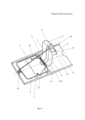
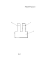
На фиг. 1 показан аксонометрический вид ловушки для ловли грызунов в рабочем состоянии; на фиг. 2 - вид вставки сверху.In FIG. 1 shows a perspective view of a trap for catching rodents in working condition; in FIG. 2 is a top view of an insert.
Ловушка (фиг. 1) включает основание 1, на котором шарнирно смонтированы подпружиненная рамка 2 и сторожок 3. Держатель 4 приманки 4а прикреплен к основанию 1, он состоит из двух Г-образных элементов 5 и 6, включающих вертикальные участки 7 и 8 и горизонтальные участки 9 и 10 соответственно. Спиральная пружина 11, взаимодействующая с рамкой 2, имеет неподвижный конец 12 и подвижный конец 13. Как видно из фиг. 1, Г-образные элементы 5 и 6 держателя 4 приманки 4а расположены друг напротив друга по разные стороны от сторожка 3 с образованием между ними зазора 13а под сторожок вдоль продольной оси 14 основания 1 ловушки.The trap (Fig. 1) includes a
В соответствии с целью изобретения, вертикальные, участки 7 и 8 Г-образных элементов 5 и 6 расположены в одной поперечной по отношению к основанию ловушки плоскости, а горизонтальные участки 9 и 10 упомянутых Г-образных элементов установлены таким образом, что их боковые кромки, одна из которых обозначена позицией 15, расположены вдоль продольной оси 14 основания 1 ловушки, причем горизонтальные участки 9 и 10 упомянутых Г-образных элементов ориентированы в сторону, противоположную по отношению к шарниру 16 сторожка 1. При этом вертикальные участки 7 и 8 упомянутых Г-образных элементов 5 и 6 могут иметь отклонение от строго вертикального положения в пределах ±40°. Далее, держатель приманки 4 (см. тж. фиг. 2) выполнен в виде одной детали - вставки с плоским основанием, жестко соединенным с основанием 1 ловушки или прижатым к основанию 1 ловушки пружиной рамки, в том числе неподвижным концом 12 пружины 11.In accordance with the purpose of the invention, the
Приманка 4а располагается в пространстве между горизонтальными участками 9 и 10 Г-образных элементов и концом сторожка 3. В качестве приманки можно использовать кусочек сыра (из твердых сортов сыра, или «подсушенный» кусочек из более мягких сортов) или хлебный сухарик.The
Процесс приведения ловушки в рабочее состояние заключается в следующем. Шарнирно закрепленную рамку 2 из нерабочего состояния поворачивают на пол-оборота, сверху на нее накладывают сторожок 3, свободный конец которого зацепляют за приманку 4а, подведенную под горизонтальные участки 9 и 10 Г-образных элементов. Тем самым приманка 4а становится силовым элементом конструкции, удерживающим ловушку во взведенном положении. Извлечение приманки 4а грызуном из держателя или съедание ее приводит к срабатыванию ловушки, при котором сторожок 3, проходя через зазор 13а вверх под воздействием давящей на него рамки 2, освобождает последнюю, так что она, ударяя по грызуну, прижимает его к основанию 1.The process of bringing the trap to working condition is as follows. The articulated
Таким образом, расположение Г-образных элементов 5 и 6 и их горизонтальных участков 9 и 10 вдоль продольной оси 14 ловушки не дает возможности сторожку выходить за пределы зазора 13а и цепляться за края горизонтальных участков 9 и 10 Г-образных элементов.Thus, the location of the L-
Источники информацииInformation sources
1. SU 1635954, А01М 23/24 A1, 1991.1. SU 1635954, A01M 23/24 A1, 1991.
2. RU 2038787, А01М 23/24 C1, 1995.2. RU 2038787, A01M 23/24 C1, 1995.
3. RU 2401531, А01М 23/24 C1, 2010.3. RU 2401531, A01M 23/24 C1, 2010.
4. RU 130204, А01М 23/24 U1, 2013 (прототип).4. RU 130204, A01M 23/24 U1, 2013 (prototype).
5. PCT WO 79/00879, А01М 23/24 A1, 1979.5. PCT WO 79/00879, A01M 23/24 A1, 1979.
Claims (4)
Priority Applications (2)
| Application Number | Priority Date | Filing Date | Title |
|---|---|---|---|
| RU2014119499/13A RU2577503C2 (en) | 2014-05-15 | 2014-05-15 | Trap for rodents |
| PCT/RU2015/000299 WO2015174891A1 (en) | 2014-05-15 | 2015-05-14 | Rodent trap |
Applications Claiming Priority (1)
| Application Number | Priority Date | Filing Date | Title |
|---|---|---|---|
| RU2014119499/13A RU2577503C2 (en) | 2014-05-15 | 2014-05-15 | Trap for rodents |
Publications (2)
| Publication Number | Publication Date |
|---|---|
| RU2014119499A RU2014119499A (en) | 2015-11-20 |
| RU2577503C2 true RU2577503C2 (en) | 2016-03-20 |
Family
ID=54480303
Family Applications (1)
| Application Number | Title | Priority Date | Filing Date |
|---|---|---|---|
| RU2014119499/13A RU2577503C2 (en) | 2014-05-15 | 2014-05-15 | Trap for rodents |
Country Status (2)
| Country | Link |
|---|---|
| RU (1) | RU2577503C2 (en) |
| WO (1) | WO2015174891A1 (en) |
Citations (4)
| Publication number | Priority date | Publication date | Assignee | Title |
|---|---|---|---|---|
| CN201430869Y (en) * | 2008-12-10 | 2010-03-31 | 赵明飞 | Rattrap |
| US7757429B1 (en) * | 2008-03-24 | 2010-07-20 | Patrick Cambio | “Z”-bar rodent trap and method of use thereof |
| RU2413411C1 (en) * | 2009-11-26 | 2011-03-10 | Василий Глебович Сазонов | Trap for rodents |
| RU130204U1 (en) * | 2013-03-05 | 2013-07-20 | Валерий Андреевич Приходченко | TRAP FOR RODENTS |
-
2014
- 2014-05-15 RU RU2014119499/13A patent/RU2577503C2/en active
-
2015
- 2015-05-14 WO PCT/RU2015/000299 patent/WO2015174891A1/en not_active Ceased
Patent Citations (4)
| Publication number | Priority date | Publication date | Assignee | Title |
|---|---|---|---|---|
| US7757429B1 (en) * | 2008-03-24 | 2010-07-20 | Patrick Cambio | “Z”-bar rodent trap and method of use thereof |
| CN201430869Y (en) * | 2008-12-10 | 2010-03-31 | 赵明飞 | Rattrap |
| RU2413411C1 (en) * | 2009-11-26 | 2011-03-10 | Василий Глебович Сазонов | Trap for rodents |
| RU130204U1 (en) * | 2013-03-05 | 2013-07-20 | Валерий Андреевич Приходченко | TRAP FOR RODENTS |
Also Published As
| Publication number | Publication date |
|---|---|
| WO2015174891A1 (en) | 2015-11-19 |
| RU2014119499A (en) | 2015-11-20 |
Similar Documents
| Publication | Publication Date | Title |
|---|---|---|
| WO2015168219A8 (en) | Controller portion of transdermal drug delivery apparatus and methods | |
| US1080623A (en) | Mouse-trap. | |
| RU130204U1 (en) | TRAP FOR RODENTS | |
| RU2577503C2 (en) | Trap for rodents | |
| RU145267U1 (en) | TRAP FOR RODENTS | |
| US1330622A (en) | Trap | |
| RU2413411C1 (en) | Trap for rodents | |
| RU2533434C2 (en) | Rodent trap | |
| RU2401531C1 (en) | Trap | |
| US1583679A (en) | Trap | |
| US783211A (en) | Fly-paper holder. | |
| RU2489853C1 (en) | Trap | |
| US2805513A (en) | Animal trap | |
| US1623841A (en) | Double-acting trap | |
| US1491829A (en) | Rat or mouse trap | |
| US1138943A (en) | Trap. | |
| US2347110A (en) | Mousetrap | |
| US1190508A (en) | Animal-trap. | |
| US2499303A (en) | Animal trap | |
| US1797923A (en) | Animal trap | |
| US1611010A (en) | Animal trap | |
| US1524831A (en) | Animal trap | |
| US1265659A (en) | Trap. | |
| US1727083A (en) | Trap | |
| US1136297A (en) | Trap. |