RU2577035C1 - Telecommunication rack-mountable patch panel - Google Patents
Telecommunication rack-mountable patch panel Download PDFInfo
- Publication number
- RU2577035C1 RU2577035C1 RU2014128492/07A RU2014128492A RU2577035C1 RU 2577035 C1 RU2577035 C1 RU 2577035C1 RU 2014128492/07 A RU2014128492/07 A RU 2014128492/07A RU 2014128492 A RU2014128492 A RU 2014128492A RU 2577035 C1 RU2577035 C1 RU 2577035C1
- Authority
- RU
- Russia
- Prior art keywords
- patch panel
- mounting
- rack
- hook
- interface
- Prior art date
Links
- 238000000034 method Methods 0.000 claims description 8
- 239000000725 suspension Substances 0.000 claims description 4
- 230000009471 action Effects 0.000 claims description 2
- 230000000694 effects Effects 0.000 abstract description 4
- 238000012856 packing Methods 0.000 abstract 1
- 239000000126 substance Substances 0.000 abstract 1
- 230000008901 benefit Effects 0.000 description 3
- 239000000835 fiber Substances 0.000 description 3
- 239000000463 material Substances 0.000 description 3
- 238000003032 molecular docking Methods 0.000 description 3
- 239000002184 metal Substances 0.000 description 2
- 230000004888 barrier function Effects 0.000 description 1
- 230000008859 change Effects 0.000 description 1
- 238000003780 insertion Methods 0.000 description 1
- 230000037431 insertion Effects 0.000 description 1
- 238000009434 installation Methods 0.000 description 1
- 230000007246 mechanism Effects 0.000 description 1
- 239000002861 polymer material Substances 0.000 description 1
Images

Classifications
-
- G—PHYSICS
- G02—OPTICS
- G02B—OPTICAL ELEMENTS, SYSTEMS OR APPARATUS
- G02B6/00—Light guides; Structural details of arrangements comprising light guides and other optical elements, e.g. couplings
- G02B6/44—Mechanical structures for providing tensile strength and external protection for fibres, e.g. optical transmission cables
- G02B6/4439—Auxiliary devices
- G02B6/444—Systems or boxes with surplus lengths
- G02B6/4452—Distribution frames
-
- H—ELECTRICITY
- H04—ELECTRIC COMMUNICATION TECHNIQUE
- H04Q—SELECTING
- H04Q1/00—Details of selecting apparatus or arrangements
- H04Q1/02—Constructional details
- H04Q1/13—Patch panels for monitoring, interconnecting or testing circuits, e.g. patch bay, patch field or jack field; Patching modules
-
- G—PHYSICS
- G02—OPTICS
- G02B—OPTICAL ELEMENTS, SYSTEMS OR APPARATUS
- G02B6/00—Light guides; Structural details of arrangements comprising light guides and other optical elements, e.g. couplings
- G02B6/44—Mechanical structures for providing tensile strength and external protection for fibres, e.g. optical transmission cables
- G02B6/4439—Auxiliary devices
- G02B6/444—Systems or boxes with surplus lengths
- G02B6/4452—Distribution frames
- G02B6/44526—Panels or rackmounts covering a whole width of the frame or rack
-
- H—ELECTRICITY
- H05—ELECTRIC TECHNIQUES NOT OTHERWISE PROVIDED FOR
- H05K—PRINTED CIRCUITS; CASINGS OR CONSTRUCTIONAL DETAILS OF ELECTRIC APPARATUS; MANUFACTURE OF ASSEMBLAGES OF ELECTRICAL COMPONENTS
- H05K7/00—Constructional details common to different types of electric apparatus
- H05K7/14—Mounting supporting structure in casing or on frame or rack
- H05K7/1401—Mounting supporting structure in casing or on frame or rack comprising clamping or extracting means
-
- H—ELECTRICITY
- H05—ELECTRIC TECHNIQUES NOT OTHERWISE PROVIDED FOR
- H05K—PRINTED CIRCUITS; CASINGS OR CONSTRUCTIONAL DETAILS OF ELECTRIC APPARATUS; MANUFACTURE OF ASSEMBLAGES OF ELECTRICAL COMPONENTS
- H05K7/00—Constructional details common to different types of electric apparatus
- H05K7/14—Mounting supporting structure in casing or on frame or rack
- H05K7/1485—Servers; Data center rooms, e.g. 19-inch computer racks
- H05K7/1488—Cabinets therefor, e.g. chassis or racks or mechanical interfaces between blades and support structures
- H05K7/1489—Cabinets therefor, e.g. chassis or racks or mechanical interfaces between blades and support structures characterized by the mounting of blades therein, e.g. brackets, rails, trays
-
- Y—GENERAL TAGGING OF NEW TECHNOLOGICAL DEVELOPMENTS; GENERAL TAGGING OF CROSS-SECTIONAL TECHNOLOGIES SPANNING OVER SEVERAL SECTIONS OF THE IPC; TECHNICAL SUBJECTS COVERED BY FORMER USPC CROSS-REFERENCE ART COLLECTIONS [XRACs] AND DIGESTS
- Y10—TECHNICAL SUBJECTS COVERED BY FORMER USPC
- Y10T—TECHNICAL SUBJECTS COVERED BY FORMER US CLASSIFICATION
- Y10T29/00—Metal working
- Y10T29/49—Method of mechanical manufacture
- Y10T29/49826—Assembling or joining
- Y10T29/49947—Assembling or joining by applying separate fastener
Abstract
Description
Область техники, к которой относится изобретениеFIELD OF THE INVENTION
Данное изобретение относится к телекоммуникационной патч-панели, которая содержит монтажный интерфейс для монтажа патч-панели в монтажную позицию в стойке, и к способу монтажа патч-панели в стойке.This invention relates to a telecommunications patch panel, which includes a mounting interface for mounting a patch panel to a mounting position in a rack, and to a method for mounting a patch panel in a rack.
Уровень техникиState of the art
Патч-панели используются в телекоммуникационных системах для обеспечения возможности изменения, при необходимости, оптоволоконных или электрических соединений. Как правило, оптоволоконные или электрические гнезда монтируются на патч-панели, и к ним имеется доступ с передней стороны патч-панели, и в них, при необходимости, вставляются так называемые коммутационные шнуры. Патч-панели часто размещаются в стойках таким образом, что коннекторы на передней стороне панели находятся на виду и легко доступны. Обычно несколько патч-панелей монтируется в стойке так, чтобы сэкономить пространство, например одна над другой, без свободного пространства между одной панелью и панелью, расположенной выше или ниже нее.Patch panels are used in telecommunication systems to provide the ability to change, if necessary, fiber or electrical connections. As a rule, fiber-optic or electrical sockets are mounted on a patch panel, and they are accessible from the front of the patch panel, and so-called patch cords are inserted into them, if necessary. Patch panels are often placed in racks so that the connectors on the front of the panel are visible and easily accessible. Usually several patch panels are mounted in a rack so as to save space, for example, one above the other, without free space between one panel and a panel located above or below it.
Монтажные стойки обычно содержат две параллельные вертикальные монтажные колонны с плоскими монтажными поверхностями, ориентированными в направлении передней стороны стойки. Каждая монтажная поверхность имеет вертикальный ряд монтажных отверстий стандартизированных форм и размеров, расположенных со стандартизированными интервалами. Патч-панель может монтироваться в стойку винтами, проходящими от передней стороны через монтажную пластину или монтажный интерфейс на обеих боковых сторонах патч-панели и через соответствующие монтажные отверстия стойки. Для фиксации патч-панели в стойке установщик завинчивает винты в монтажные колонны или в соответствующие гайки, расположенные позади монтажных отверстий.Mounting racks typically comprise two parallel vertical mounting columns with flat mounting surfaces oriented toward the front of the rack. Each mounting surface has a vertical row of mounting holes of standardized shapes and sizes spaced at standardized intervals. The patch panel can be rack mounted with screws extending from the front through the mounting plate or mounting interface on both sides of the patch panel and through the corresponding mounting holes of the rack. To fix the patch panel in the rack, the installer tightens the screws in the mounting columns or in the corresponding nuts located behind the mounting holes.
Монтаж патч-панели в стойку силами одного человека может быть затруднительным, поскольку патч-панель необходимо удерживать в монтажном положении одной рукой, при этом винты сначала на одной стороне патч-панели, а затем на другой стороне необходимо завинчивать второй рукой. Если к патч-панели уже подключены коммутационные шнуры, монтаж еще более усложняется, потому что одной рукой нужно удерживать вес самой патч-панели и дополнительный вес коммутационных шнуров, тогда как вторая рука завинчивает винты. Демонтаж патч-панелей из стойки может быть таким же затруднительным, потому что патч-панель нужно удерживать одной рукой, в то время как вторая рука должна вывинчивает винты.Installing the patch panel in a rack by one person can be difficult, since the patch panel must be held in the mounting position with one hand, while the screws must first be screwed on one side of the patch panel and then screwed on the other side with the other hand. If patch cords are already connected to the patch panel, installation is even more complicated, because with one hand you need to hold the weight of the patch panel itself and the additional weight of the patch cords, while the other hand tightens the screws. Removing the patch panels from the rack can be just as difficult, because the patch panel must be held with one hand, while the other hand must unscrew the screws.
Традиционный монтаж патч-панели показан, например, в публикации международной патентной заявки WO 2010/080745, которая описывает монтажный кронштейн стойки, присоединенный к монтажному участку стороны патч-панели, и в публикации патентной заявки США 2008/0115956, в которой патч-панель имеет раму, на которой имеются монтажные элементы на противоположных продольных концах рамы для монтажа патч-панели во множестве положений на сетевой стойке с использованием винтов, которая может быть вставлена посредством монтажных элементов и посредством монтажных проемов в стойку с тем, чтобы закрепить патч-панель в стойке. Патентная заявка США 2006/0018622 А1 описывает патч-панель, которая шарнирно монтируется в выдвижной ящик. Такой выдвижной ящик имеет кабельный лоток, в котором, в свою очередь, имеются зажимы-ограничители, которые позволяют патч-панели перемещаться между прямым положением и повернутым положением.Conventional mounting of a patch panel is shown, for example, in the publication of international patent application WO 2010/080745, which describes a rack mounting bracket attached to a mounting portion of a side of a patch panel, and in the publication of US patent application 2008/0115956, in which the patch panel has a frame on which there are mounting elements at opposite longitudinal ends of the frame for mounting the patch panel in a plurality of positions on a network rack using screws that can be inserted by means of mounting elements and by means of mounting openings in the rack in order to secure the patch panel to the rack. US Patent Application 2006/0018622 A1 describes a patch panel that is pivotally mounted in a drawer. Such a drawer has a cable tray in which, in turn, there are limit clamps that allow the patch panels to move between a straight position and a rotated position.
Предпринимались попытки сделать монтаж патч-панелей в стойки более легким. JP 2005209388 А2 описывает раму патч-панели, которая монтируется в стойку с использованием монтажных винтов. Эти монтажные винты проходят в фиксирующие отверстия рамы через вертикальные щели, выходя из этих фиксирующих отверстий. Такие монтажные винты могут принимать на себя часть веса рамы патч-панели, пока монтажные винты еще не затянуты полностью. Патч-панель, которую нужно монтировать в стойку, может находиться в подвешенном состоянии в ее конечном монтажном положении. В этом подвешенном состоянии ее вес поддерживается стойкой, так что установщик может двумя руками жестко закрепить ее в стойке, например, затянув винты.Attempts have been made to make installing patch panels in racks easier. JP 2005209388 A2 describes a patch panel frame that is rack mounted using mounting screws. These mounting screws pass into the fixing holes of the frame through vertical slots, leaving these fixing holes. Such mounting screws can take on part of the weight of the patch panel frame, while the mounting screws are not yet fully tightened. The patch panel that needs to be rack mounted may be suspended in its final mounting position. In this suspended state, its weight is supported by the rack, so that the installer can firmly fix it in the rack with both hands, for example, by tightening the screws.
Монтажные позиции выше или ниже данной монтажной позиции, в которой должна быть установлена патч-панель, можно занять другими патч-панелями или иным оборудованием. Обычно свободное пространство или промежутки, расположенные выше или ниже впритык к монтажным положениям, нежелательны, поскольку пространство в стойке очень ценно. Таким образом, желательно, чтобы патч-панель, которую необходимо монтировать в стойку, могла бы находиться в подвешенном состоянии в ее конечном монтажной позиции, без необходимости оставлять свободное пространство в стойке выше или ниже того пространства, которое эта патч-панель занимает в ее конечной монтажной позиции. Данное изобретение решает эту задачу.Mounting positions above or below the mounting position in which the patch panel is to be installed can be occupied by other patch panels or other equipment. Usually free space or gaps located above or below close to the mounting positions are undesirable because rack space is very valuable. Thus, it is desirable that the patch panel that needs to be mounted in the rack can be suspended in its final mounting position, without having to leave free space in the rack above or below the space that this patch panel occupies in its final mounting position. This invention solves this problem.
Раскрытие изобретенияDisclosure of invention
Настоящее изобретение предлагает телекоммуникационную патч-панель, содержащую монтажный интерфейс для монтажа патч-панели в монтажной позиции в стойке, при этом такой монтажный интерфейс содержит приспособление для фиксации для подвешивания и жесткой фиксации патч-панели в монтажной позиции в стойке, отличающуюся тем, что приспособление (приспособления) для фиксации можно линейно перемещать относительно монтажного интерфейса в первом направлении между первым положением и вторым положением и во втором направлении между вторым положением и третьим положением.The present invention provides a telecommunications patch panel comprising a mounting interface for mounting a patch panel in a mounting position in a rack, wherein such a mounting interface includes a locking device for hanging and rigidly fixing a patch panel in a mounting position in a rack, characterized in that (fixtures) for fixing can be linearly moved relative to the mounting interface in the first direction between the first position and the second position and in the second direction between the second position Niemi and a third position.
Патч-панель, в соответствии с данным изобретением, может располагаться в стойке в ее монтажной позиции без необходимости в свободном пространстве в стойке выше или ниже того пространства, которое патч-панель занимает в ее конечной монтажной позиции. Другими словами, она может быть помещена в ее монтажную позицию и располагаться в ее монтажной позиции, даже если дополнительные патч-панели уже смонтированы выше и ниже ее монтажной позиции, без какого-либо свободного пространства в стойке между данной патч-панелью и патч-панелями выше и ниже нее. Патч-панель может, например, быть подвешена в монтажной позиции посредством перемещения приспособления для фиксации в первом направлении из первого положения во второе положение без необходимости перемещения патч-панели вверх или вниз в стойке. Патч-панель может жестко фиксироваться в стойке, например, посредством перемещения приспособления для фиксации во втором направлении из второго положения в третье положение, без необходимости перемещения патч-панели вверх, вниз или в стороны в стойке.The patch panel, in accordance with this invention, can be located in the rack in its mounting position without the need for free space in the rack above or below the space that the patch panel occupies in its final mounting position. In other words, it can be placed in its mounting position and located in its mounting position, even if additional patch panels are already mounted above and below its mounting position, without any free space in the rack between this patch panel and the patch panels above and below her. The patch panel may, for example, be suspended in the mounting position by moving the fixture for fixing in the first direction from the first position to the second position without the need to move the patch panel up or down in the rack. The patch panel can be rigidly fixed in the rack, for example, by moving the fixture for fixing in the second direction from the second position to the third position, without the need to move the patch panel up, down or sideways in the rack.
Патч-панель, в соответствии с данным изобретением, содержит монтажный интерфейс. Монтажный интерфейс может быть соединен с патч-панелью. Монтажный интерфейс может быть соединен с патч-панелью на стороне патч-панели. Патч-панель может содержать два таких монтажных интерфейса, по одному на каждой боковой стороне патч-панели. Монтажный интерфейс может быть выполнен с возможностью входить в зацепление с монтажными отверстиями, причем отверстия могут располагаться на монтажных поверхностях стойки для монтажа в ней телекоммуникационного оборудования. Патч-панель и/или монтажный интерфейс могут быть, в частности, выполнены с возможностью входить в зацепление с монтажными отверстиями, расположенными на монтажных поверхностях стандартизированной стойки, подобной, например, стандартизированной 19-дюймовой стойке в соответствии со стандартом IEC 60297 Международной электротехнической комиссии. Монтажные отверстия могут иметь круглую форму или прямоугольную или квадратную форму. Они могут иметь квадратную форму, при которой каждая сторона квадрата имеет длину 0.375 дюйма. Они могут располагаться в ряд вертикально. Они могут располагаться в ряд повторяющихся наборов из трех монтажных отверстий с интервалами 0.625 дюйма между центрами монтажных отверстий в одном наборе и 0.5 дюйма между ближайшими монтажными отверстиями соседних наборов. Набор из трех монтажных отверстий может определять монтажную позицию патч-панели. Монтажная позиция патч-панели - это позиция патч-панели в стойке, в которой находится эта патч-панель, когда она смонтирована и жестко зафиксирована в стойке через монтажные отверстия. Патч-панель может находиться в монтажной позиции независимо от того, зафиксирована она или нет, подвешена или нет, или же поддерживаема вручную или нет.The patch panel, in accordance with this invention, contains a mounting interface. The mounting interface can be connected to a patch panel. The mounting interface can be connected to the patch panel on the side of the patch panel. A patch panel can contain two of these mounting interfaces, one on each side of the patch panel. The mounting interface may be configured to engage with mounting holes, and the holes may be located on the mounting surfaces of the rack for mounting telecommunication equipment therein. The patch panel and / or mounting interface may in particular be adapted to engage with mounting holes located on mounting surfaces of a standardized rack, such as, for example, a standardized 19-inch rack in accordance with IEC 60297 of the International Electrotechnical Commission. Mounting holes can be round or rectangular or square. They can have a square shape in which each side of the square has a length of 0.375 inches. They can be arranged in a row vertically. They can be arranged in a series of repeating sets of three mounting holes at 0.625 inch intervals between the centers of the mounting holes in one set and 0.5 inch between the nearest mounting holes of adjacent sets. A set of three mounting holes can determine the mounting position of the patch panel. The mounting position of the patch panel is the position of the patch panel in the rack where the patch panel is located when it is mounted and rigidly fixed in the rack through the mounting holes. The patch panel can be in the mounting position regardless of whether it is fixed or not, suspended or not, or supported manually or not.
Монтажный интерфейс патч-панели, в соответствии с данным изобретением, содержит приспособление для фиксации для подвешивания и жесткой фиксации монтажного интерфейса в стойке. Подвешивание патч-панели в стойке обеспечивает опору для патч-панели в том смысле, что ее вес поддерживается и что она остается на своем месте, если не прилагать дополнительные внешние силы. В подвешенном состоянии патч-панель может по-прежнему перемещаться относительно стойки. В подвешенном состоянии патч-панель может не быть жестко зафиксирована в стойке. Приспособление для фиксации может содержать крюк. Крюк может сделать приспособление для фиксации пригодным для подвешивания патч-панели в стойке. Приспособление для фиксации может содержать два или более крюков, которые могут сделать приспособление для фиксации пригодным для подвешивания патч-панели в стойке.The mounting interface of the patch panel, in accordance with this invention, contains a fixture for fixing for hanging and rigidly fixing the mounting interface in the rack. Suspension of the patch panel in the rack provides support for the patch panel in the sense that its weight is supported and that it remains in place without additional external forces. When suspended, the patch panel can still move relative to the rack. When suspended, the patch panel may not be rigidly fixed in the rack. The fixture for fixing may contain a hook. The hook can make the fixture suitable for hanging the patch panel in a rack. The fixture may include two or more hooks that may make the fixture suitable for hanging the patch panel in a rack.
Приспособление для фиксации подходит для жесткой фиксации патч-панели в стойке. Надежная фиксация патч-панели в стойке обеспечивает опору для патч-панели в том смысле, что ее вес поддерживается и что она жестко зафиксирована в стойке так, что патч-панель больше не может перемещаться относительно стойки, даже если к патч-панели приложены дополнительные внешние силы. В частности, после жесткой фиксации, то есть в зафиксированном состоянии, патч-панель не может быть удалена из стойки, пока не будет отсоединено приспособление для фиксации. Приспособление для фиксации может быть отсоединяемым.The fixture is suitable for rigidly fixing the patch panel in the rack. Reliably fixing the patch panel in the rack provides support for the patch panel in the sense that its weight is supported and that it is rigidly fixed in the rack so that the patch panel can no longer move relative to the rack, even if additional external panels are attached to the patch panel strength. In particular, after a rigid fixation, that is, in a locked state, the patch panel cannot be removed from the rack until the fixation device is disconnected. The fixture may be detachable.
Приспособление или приспособления для фиксации могут перемещаться относительно монтажного интерфейса. Это необходимо понимать таким образом, что приспособление или приспособления для фиксации могут перемещаться, по меньшей мере, относительно одной из других частей монтажного интерфейса. Приспособление для фиксации может перемещаться относительно части монтажного интерфейса, соединяющей монтажный интерфейс с другой частью патч-панели, например, части, которая соединяет монтажный интерфейс и переднюю поверхность патч-панели. Приспособление для фиксации может совершать линейные и/или вращательные перемещения относительно монтажного интерфейса.The fixture or fixtures for locking may move relative to the mounting interface. This must be understood in such a way that the fixture or fixtures for locking can move at least relative to one of the other parts of the mounting interface. The fixture can be moved relative to the part of the mounting interface connecting the mounting interface to another part of the patch panel, for example, the part that connects the mounting interface and the front surface of the patch panel. The fixture for fixing can make linear and / or rotational movements relative to the mounting interface.
Монтажный интерфейс патч-панели, в соответствии с данным изобретением, может содержать неподвижную часть и часть, которая может перемещаться относительно неподвижной части. Неподвижная часть может быть соединена с передней пластиной патч-панели. Подвижная часть содержит приспособление для фиксации для подвешивания и жесткого закрепления патч-панели в стойке. Неподвижная часть может иметь форму, подходящую для упора в монтажную поверхность стойки, когда патч-панель находится в монтажной позиции. Неподвижная часть может содержать узел интерфейсного блока. Узел интерфейсного блока может содержать заднюю поверхность, которая выполнена с возможностью упора в монтажную поверхность стойки, когда патч-панель находится в монтажной позиции. Узел интерфейсного блока в общем случае может охватывать приспособление для фиксации. Узел интерфейсного блока может содержать полимерный материал или металл. Узел интерфейсного блока может иметь просвет, через который может выступать часть приспособления для фиксации. Выступ приспособления для фиксации может быть выполнен с возможностью введния в зацепление с монтажным отверстием стойки таким образом, что патч-панель может быть подвешена и/или жестко зафиксирована в монтажной позиции стойки, когда патч-панель находится в монтажной позиции. Выступ приспособления для фиксации может быть в форме крюка.The mounting interface of the patch panel, in accordance with this invention, may include a fixed part and a part that can move relative to the fixed part. The fixed part can be connected to the front plate of the patch panel. The movable part comprises a fixing device for hanging and rigidly fixing the patch panel in the rack. The fixed portion may have a shape suitable for abutting against the mounting surface of the rack when the patch panel is in the mounting position. The fixed part may comprise an interface unit assembly. The interface unit assembly may include a rear surface that is capable of abutting against the mounting surface of the rack when the patch panel is in the mounting position. An interface unit assembly may generally encompass a fixture for fixation. The interface unit assembly may comprise polymeric material or metal. The interface unit assembly may have a clearance through which part of the fixture may protrude. The protrusion of the fixture for fixation can be made with the possibility of engaging with the mounting hole of the rack so that the patch panel can be suspended and / or rigidly fixed in the mounting position of the rack when the patch panel is in the mounting position. The protrusion of the fixture may be in the form of a hook.
Приспособление для фиксации может иметь просвет с резьбой. Монтажный интерфейс может содержать элемент с резьбой, например винт, который может входить в зацепление с этим просветом с резьбой.The fixture may have a threaded clearance. The mounting interface may comprise a threaded element, for example a screw, which may engage with this threaded lumen.
Приспособление для фиксации перемещается между первым положением и вторым положением. Оно может совершать линейные перемещения между первым положением и вторым положением. Первым положением может быть нерабочее положение, при котором, когда патч-панель размещена в монтажной позиции, приспособление для фиксации не введено в зацепление со стойкой, так что патч-панель можно удалить из стойки. В этом положении приспособления для фиксации патч-панель можно удалить из стойки вручную.The fixture for locking moves between the first position and the second position. It can make linear movements between the first position and the second position. The first position may be an inoperative position in which, when the patch panel is placed in the mounting position, the locking device is not engaged with the stand, so that the patch panel can be removed from the stand. In this position, the fixtures for fixing the patch panel can be removed from the rack manually.
Вторым положением может быть подвешенное положение, при котором, когда патч-панель расположена в монтажной позиции, приспособление для фиксации введено в зацепление со стойкой таким образом, что патч-панель подвешена в стойке в монтажной позиции. Когда патч-панель подвешена в стойке, вес патч-панели поддерживается стойкой. Когда приспособление для фиксации находится в подвешенном положении, патч-панель может не быть жестко зафиксирована в стойке, то есть патч-панель может по-прежнему перемещаться относительно стойки.The second position may be a suspended position, in which, when the patch panel is located in the mounting position, the locking device is engaged with the rack so that the patch panel is suspended in the rack in the mounting position. When the patch panel is suspended in a rack, the weight of the patch panel is supported by the rack. When the fixture is in a suspended position, the patch panel may not be rigidly fixed in the rack, that is, the patch panel may still move relative to the rack.
Первым направлением может быть горизонтальное или вертикальное направление. Первым направлением может быть горизонтальное или вертикальное направление относительно монтажного интерфейса, когда патч-панель расположена в монтажной позиции стойки. Второе положение приспособления для фиксации может располагаться над первым положением или под первым положением, когда патч-панель располагается в монтажной позиции.The first direction may be a horizontal or vertical direction. The first direction may be a horizontal or vertical direction relative to the mounting interface when the patch panel is located in the mounting position of the rack. The second position of the fixture may be located above the first position or below the first position when the patch panel is in the mounting position.
Приспособление для фиксации может перемещаться между вторым положением и третьим положением. Оно может совершать линейные перемещения между вторым положением и третьим положением. Третьим положением может быть положение фиксации, в котором, когда патч-панель расположена в монтажной позиции, приспособление для фиксации жестко фиксирует патч-панель в стойке. В этом третьем положении приспособление для фиксации может быть состыковано со стойкой таким образом, что патч-панель будет жестко зафиксирована в монтажной позиции в стойке.The fixture can be moved between the second position and the third position. It can make linear movements between the second position and the third position. The third position may be a fixation position in which, when the patch panel is located in the mounting position, the fixture for fixation rigidly fixes the patch panel in the rack. In this third position, the fixture can be docked to the rack so that the patch panel is rigidly locked in the mounting position in the rack.
Вторым направлением может быть вертикальное или горизонтальное направление. Вторым направлением может быть вертикальное или горизонтальное направление относительно монтажного интерфейса, когда патч-панель расположена в монтажной позиции в стойке. В частности, вторым направлением может быть горизонтальное направление вперед/назад относительно монтажного интерфейса, когда патч-панель расположена в монтажной позиции в стойке. Направлением вперед-назад может быть направление, обычно параллельное поверхности, перпендикулярной передней поверхности патч-панели. Второе положение может быть расположено позади от третьего положения.The second direction may be a vertical or horizontal direction. The second direction may be a vertical or horizontal direction relative to the mounting interface when the patch panel is located in the mounting position in the rack. In particular, the second direction may be a horizontal forward / backward direction relative to the mounting interface when the patch panel is located in the mounting position in the rack. The back and forth direction may be a direction usually parallel to a surface perpendicular to the front surface of the patch panel. The second position may be located behind the third position.
Приспособление для фиксации может перемещаться вручную. Это может быть преимуществом, поскольку может не требоваться никаких инструментов для перемещения приспособления для фиксации. Также при этом может быть возможно перемещать средство фиксации той же рукой, которая поддерживает часть веса или весь вес патч-панели.The fixture can be moved manually. This may be an advantage since no tools may be required to move the fixture. It may also be possible to move the fixing means with the same hand, which supports part of the weight or the entire weight of the patch panel.
Приспособление для фиксации может содержать деталь в форме крюка или две детали в форме крюка. Деталь в форме крюка может быть выполнена с возможностью введения в зацепление с кромкой просвета в стойке. Таким образом можно обеспечить особую простоту конструкции монтажного интерфейса в данном изобретении.The fixture may comprise a hook-shaped part or two hook-shaped parts. The hook-shaped part may be adapted to engage with the edge of the lumen in the strut. Thus, it is possible to provide a particularly simple design of the mounting interface in this invention.
Монтажный интерфейс может содержать пружину или другой тип упругого элемента. Приспособление для фиксации может перемещаться против действия силы пружины или упругого элемента. Пружина или упругий элемент может определять стабильное положение приспособления для фиксации относительно других частей монтажного интерфейса или патч-панели, относительно которых это приспособление для фиксации является подвижным. Это также может предотвращать нежелательное или случайное перемещение приспособления для фиксации из стабильного положения. Пружина или упругий элемент могут перемещаться вместе с приспособлением для фиксации относительно других частей монтажного интерфейса или относительно патч-панели или же могут быть неподвижными относительно патч-панели.The mounting interface may comprise a spring or other type of resilient member. The fixture for fixing can be moved against the action of the force of a spring or an elastic element. The spring or elastic element may determine the stable position of the fixture relative to other parts of the mounting interface or patch panel, relative to which this fixture is movable. It can also prevent unwanted or accidental movement of the fixture from a stable position. The spring or elastic element can be moved together with the fixture for fixing relative to other parts of the mounting interface or relative to the patch panel or can be stationary relative to the patch panel.
Первое направление может быть перпендикулярно второму направлению. Первое или второе направление может быть направлением, параллельным передней поверхности патч-панели. Первое или второе направление может быть направлением, перпендикулярным передней поверхности патч-панели. Первое или второе направление может быть направлением, параллельным направлению по высоте стойки, к которой необходимо прикрепить патч-панель. Перемещение в первом направлении может не зависеть от перемещения во втором направлении. Способность перемещаться в двух направлениях, перпендикулярных друг другу, дает преимущество в том смысле, что перемещение в одном направлении можно использовать для достижения первого механического эффекта, подобного, например, подвешиванию патч-панели, тогда как перемещение в другом направлении можно использовать для получения второго независимого механического эффекта. Таким вторым эффектом может, например, быть надежная фиксация монтажного интерфейса и патч-панели в стойке.The first direction may be perpendicular to the second direction. The first or second direction may be a direction parallel to the front surface of the patch panel. The first or second direction may be a direction perpendicular to the front surface of the patch panel. The first or second direction may be a direction parallel to the height direction of the stand to which the patch panel needs to be attached. The movement in the first direction may not depend on the movement in the second direction. The ability to move in two directions perpendicular to each other gives an advantage in the sense that moving in one direction can be used to achieve a first mechanical effect, such as, for example, suspending a patch panel, while moving in the other direction can be used to obtain a second independent mechanical effect. Such a second effect may, for example, be a reliable fixation of the mounting interface and the patch panel in the rack.
Монтажный интерфейс может содержать элемент с резьбой. Посредством поворота элемента с резьбой приспособление для фиксации может перемещаться относительно монтажного интерфейса. Приспособление для фиксации может перемещаться в первом направлении или во втором направлении посредством поворота элемента с резьбой. Приспособление для фиксации может совершать линейные перемещения в первом направлении или во втором направлении посредством поворота элемента с резьбой. Элемент с резьбой может быть, например, винтом или штифтом с резьбой. Приспособление для фиксации может перемещаться в третье положение посредством поворота элемента с резьбой. Приспособление для фиксации может перемещаться в третье положение посредством поворота элемента с резьбой по часовой стрелке. Элемент с резьбой дает преимущество в том смысле, что он может быть способен передавать нужную силу для жесткой фиксации патч-панели в стойке посредством перемещения приспособления для фиксации, например, посредством перемещения приспособления для фиксации в положение фиксации.The mounting interface may include a threaded element. By turning the threaded element, the fixture can be moved relative to the mounting interface. The fixture for fixing can be moved in the first direction or in the second direction by turning the threaded element. The fixture for locking can make linear movements in the first direction or in the second direction by rotating the threaded element. The threaded element may be, for example, a screw or a threaded pin. The fixture for locking can be moved to the third position by turning the threaded element. The fixture can be moved to the third position by turning the threaded element clockwise. A threaded element provides an advantage in that it can be capable of transmitting the necessary force to firmly fix the patch panel in the rack by moving the fixture, for example, by moving the fixture to the locked position.
Приспособление для фиксации может быть выполнено с возможностью жесткой фиксации патч-панели в стойке посредством зажимания части стойки между приспособлением для фиксации и другой частью монтажного интерфейса. Зажимание - это особенно простой механизм фиксации патч-ианели. Зажимание обычно может потребовать лишь небольшого перемещения зажимающего элемента для жесткой фиксации монтажного интерфейса и патч-панели, соединенной с ним, или для удаления монтажного интерфейса или патч-панели из стойки.The fixture for fixing can be made with the possibility of rigidly fixing the patch panel in the rack by clamping part of the rack between the fixture and another part of the mounting interface. Clamping is a particularly simple fixation mechanism for the patch ianeli. Clamping usually may require only a slight movement of the clamping element to firmly fix the mounting interface and the patch panel connected to it, or to remove the mounting interface or patch panel from the rack.
Монтажный интерфейс или узел интерфейсного блока может содержать приспособление для расположения, выполненное для расположения патч-панели в монтажной позиции в стойке. Приспособление для расположения может облегчать расположение, когда патч-панель перемещается в монтажное положение. Приспособление для расположения может содержать выступ. Выступ может выступать из монтажного интерфейса или из интерфейсного узла в направлении назад. Приспособление для расположения может иметь форму и положение, подходящие для вставки в монтажное отверстие стойки таким образом, что приспособление для фиксации направляется в положение, в котором оно может быть состыковано с монтажным отверстием стойки таким образом, что это приспособление для фиксации подвешивает и/или жестко фиксирует патч-панель в стойке. Приспособлением для расположения может, например, быть штифт расположения, который выполнен с возможностью выступать в просвет в стойке, в котором необходимо монтировать патч-панель и монтажный интерфейс.The mounting interface or interface unit assembly may include an arrangement for locating the patch panel in the mounting position in the rack. The positioning device may facilitate positioning when the patch panel is moved to the mounting position. The arrangement may comprise a protrusion. The protrusion may protrude from the mounting interface or from the interface node in the backward direction. The arrangement may have a shape and position suitable for insertion into the rack mounting hole so that the locking device is guided to a position in which it can be joined to the rack mounting hole so that this fixing device hangs and / or rigidly fixes the patch panel in the rack. The arrangement device may, for example, be an arrangement pin which is configured to protrude into the lumen in a rack in which it is necessary to mount the patch panel and the mounting interface.
Приспособление для расположения может быть упругим. Приспособление для расположения может иметь элемент задержки. Элемент задержки может быть выполнен с возможностью введение в зацепление с частью стойки, в которой необходимо монтировать патч-панель. Элемент задержки может быть выполнен с возможностью защелкивания позади края монтажного отверстия стойки. Элемент задержки может предотвращать случайное перемещение монтажного интерфейса, когда патч-панель находится в монтажной позиции и патч-панель не подвешена и не зафиксирована в стойке. Приспособление для расположения на монтажном интерфейсе данного изобретения может облегчать точное расположение патч-панели относительно стойки, и, таким образом, может позволить избежать необходимости в дальнейшем перемещении патч-панели в ее монтажной позиции или удаления и расположения заново патч-панели из-за неправильного ее расположения.The arrangement may be resilient. The arrangement may have a delay element. The delay element may be configured to engage with a portion of the rack in which the patch panel needs to be mounted. The delay element may be latched behind the edge of the rack mounting hole. The delay element can prevent accidental movement of the mounting interface when the patch panel is in the mounting position and the patch panel is not suspended or locked in the rack. The arrangement for mounting on the mounting interface of the present invention can facilitate the exact location of the patch panel relative to the rack, and thus can avoid the need for further movement of the patch panel in its mounting position or removal and re-location of the patch panel due to improper location.
Монтажный интерфейс может быть выполнен с возможностью подвешивания и жесткой фиксации патч-панели в монтажной позиции стандартизированной 19-дюймовой стойки. Это повышает универсальность патч-панели, поскольку допускает монтаж патч-панели в различных стойках стандартизированного 19-дюймового типа.The mounting interface can be configured to suspend and firmly fix the patch panel in the mounting position of a standardized 19-inch rack. This increases the versatility of the patch panel because it allows the patch panel to be mounted in various racks of a standardized 19-inch type.
Изобретение также предлагает способ монтажа телекоммуникационной патч-панели в монтажной позиции стойки, последовательно содержащий этапы:The invention also provides a method for mounting a telecommunications patch panel in a mounting position of a rack, sequentially comprising the steps of:
a) обеспечения стойки, содержащей монтажную позицию для патч-панели;a) providing a rack containing the mounting position for the patch panel;
b) обеспечения телекоммуникационной патч-панели, как описано ранее;b) providing a telecommunications patch panel as previously described;
c) размещения патч-панели в монтажной позиции стойки;c) placing the patch panel in the mounting position of the rack;
d) перемещения приспособления для фиксации в первом направлении из первого положения во второе положение; иd) moving the fixture for fixing in the first direction from the first position to the second position; and
e) перемещения приспособления для фиксации во втором направлении из второго положения в третье положение.e) moving the fixture for fixing in the second direction from the second position to the third position.
Этап d) может быть выполнен вручную или с использованием инструмента. Этап е) перемещения приспособления для фиксации в положение фиксации может быть выполнен поворотом элемента с резьбой, который может содержаться в монтажном интерфейсе. Этап е) может быть выполнен вручную или с использованием инструмента.Step d) may be performed manually or using a tool. Step e) moving the fixture to the fixation position can be accomplished by turning a threaded element that may be contained in the mounting interface. Step e) may be performed manually or using a tool.
В описанном выше способе первым положением может быть нерабочее положение, при котором, когда патч-панель расположена в монтажной позиции, приспособление для фиксации не введено в зацепление со стойкой, так что патч-панель можно удалить из стойки.In the method described above, the first position may be an inoperative position in which, when the patch panel is in the mounting position, the locking device is not engaged with the rack, so that the patch panel can be removed from the rack.
В описанном выше способе вторым положением может быть подвешенное положение, при котором, когда патч-панель расположена в монтажной позиции, приспособление для фиксации введено в зацепление со стойкой таким образом, что патч-панель подвешена в стойке в монтажной позиции. Вторым положением может быть положение, в котором патч-панель может не быть жестко зафиксирована в стойке.In the method described above, the second position may be a suspended position in which, when the patch panel is located in the mounting position, the fixture is engaged with the rack so that the patch panel is suspended in the rack in the mounting position. The second position may be a position in which the patch panel may not be rigidly fixed in the rack.
В описанном выше способе третьим положением может быть положение фиксации, в котором, когда патч-панель расположена в монтажной позиции, приспособление или приспособления для фиксации жестко фиксируют патч-панель в монтажной позиции в стойке.In the method described above, the third position may be a fixation position, in which, when the patch panel is located in the mounting position, fixtures or fixtures to fix the patch panel rigidly in the mounting position in the rack.
Краткое описание чертежейBrief Description of the Drawings
Настоящее изобретение будет далее описано более подробно со ссылкой на следующие чертежи, дающие примеры конкретных вариантов осуществления данного изобретения:The present invention will now be described in more detail with reference to the following drawings, giving examples of specific embodiments of the present invention:
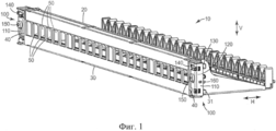
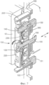
Фиг. 1 - вид в перспективе патч-панели в соответствии с настоящим изобретением, содержащий два монтажных интерфейса;FIG. 1 is a perspective view of a patch panel in accordance with the present invention, comprising two mounting interfaces;
Фиг. 2 - вид спереди в перспективе патч-панели и одного из монтажных интерфейсов в соответствии с Фиг. 1 в монтажной позиции стойки;FIG. 2 is a front perspective view of a patch panel and one of the mounting interfaces in accordance with FIG. 1 in the mounting position of the rack;
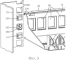
Фиг. 3 - вид в перспективе монтажного интерфейса с Фиг. 2, показанный сзади;FIG. 3 is a perspective view of the mounting interface of FIG. 2 shown at the back;
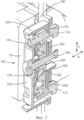
Фиг. 4 - покомпонентный вид монтажного интерфейса с Фиг. 2;FIG. 4 is an exploded view of the mounting interface of FIG. 2;
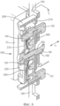
Фиг. 5 - вид в разрезе и в перспективе монтажного интерфейса с Фиг. 2 с приспособлением для фиксации в первом положении;FIG. 5 is a sectional and perspective view of the mounting interface of FIG. 2 with a fixture for fixing in the first position;
Фиг. 6 - вид в разрезе и в перспективе монтажного интерфейса с Фиг. 2 с приспособлением для фиксации во втором положении; иFIG. 6 is a sectional and perspective view of the mounting interface of FIG. 2 with a fixture for fixing in the second position; and
Фиг. 7 - вид в разрезе и в перспективе монтажного интерфейса с Фиг. 2 с приспособлением для фиксации в третьем положении.FIG. 7 is a sectional and perspective view of the mounting interface of FIG. 2 with a fixture for fixing in the third position.
Осуществление изобретенияThe implementation of the invention
Здесь и далее различные варианты осуществления настоящего изобретения описаны и показаны на чертежах, при этом подобные элементы снабжены одинаковыми ссылочными позициями.Hereinafter, various embodiments of the present invention are described and shown in the drawings, wherein like elements are provided with the same reference numerals.
На Фиг. 1 показан вид в перспективе передней поверхности телекоммуникационной патч-панели 10 в соответствии с изобретением. Патч-панель 10 имеет верхнюю кромку 20, нижнюю кромку 30 и две боковых кромки 40. Патч-панель 10 содержит горизонтальный ряд просветов 50, в которые можно монтировать электрические или оптоволоконные телекоммуникационные гнезда. Соответствующие подходящие электрические коннекторы или подходящие оптоволоконные коннекторы коммутационных шнуров можно вставлять в эти гнезда. На каждой боковой стороне патч-панель 10 содержит монтажный интерфейс 100. Каждый из этих монтажных интерфейсов 100 служит для монтажа патч-панели 10 в монтажную позицию в стойке. Каждый монтажный интерфейс 100 неподвижно соединен с патч-панелью 10 таким образом, что передняя пластина патч-панели 10 продолжается таким образом, чтобы формировать часть монтажных интерфейсов 100. Монтажные интерфейсы 100 на каждой стороне патч-панели 10 идентичны, за исключением того, что один зеркально отражает другой по горизонтали, то есть справа налево. Каждый монтажный интерфейс 100 содержит узел 110 интерфейсного блока и скобу-крюк 120, которая перемещается относительно узла 110 интерфейсного блока. Скоба-крюк 120 - это приспособление для фиксации для подвешивания и жесткой фиксации монтажного интерфейса 100 и всей патч-панели 10 в стойке. Скоба-крюк 120 содержит верхний крюк 130, нижний крюк 131 и рычажок 140. При ориентации патч-панели 10 в том виде, как она монтируется в стойке, верхний крюк 130 располагается над нижним крюком 131. При ориентации патч-панели 10 в том виде, как она монтируется в стойке, верхний крюк 130 и нижний крюк 131 выдвигаются в направлении назад. Рычажок 140 выдвигается в направлении вперед, чтобы к нему был доступ у установщика. На Фиг. 1 видны только два крюка 130, 131 и рычажок 140 монтажного интерфейса 100 на правой стороне патч-панели 10. Узел 110 интерфейсного блока - это неподвижная часть монтажного интерфейса 100, которая неподвижно соединена с патч-панелью 10. Скоба-крюк 120 перемещается относительно узла 110 интерфейсного блока и, следовательно, относительно монтажного интерфейса 100. Скоба-крюк 120 перемещается относительно монтажного интерфейса 100 и в вертикальном и, независимо, в горизонтальном направлениях, указанных соответствующими стрелками "V" и "Н". Она может перемещаться вручную в вертикальном направлении относительно узла 110 интерфейсного блока при помощи рычажка 140, который соединен со скобой-крюком 120. Рычажок 140 проходит через просвет в узле 110 интерфейсного блока и выдвигается из узла 110 интерфейсного блока в направлении передней стороны монтажного интерфейса 100. Скоба-крюк 120 также перемещается в горизонтальном направлении, которое перпендикулярно передней поверхности патч-панели 10, то есть в направлении «спереди-назад», указанной стрелкой «Н». Скоба-крюк 120 может перемещаться относительно узла 110 интерфейсного блока в горизонтальном направлении «Н» посредством поворота затягивающего винта 150. Резьба затягивающего винта 150 совпадает с соответствующей резьбой в скобе-крюке 120. Затягивающий винт 150 соединен со скобой-крюком 120 посредством соответствующей резьбы. Затягивающий винт 150 перемещается вертикально по мере того, как вертикально перемещается скоба-крюк 120. Затягивающий винт 150 может, таким образом, перемещаться относительно узла 110 интерфейсного блока. Головка затягивающего винта 150 упирается во внешнюю переднюю поверхность узла 110 интерфейсного блока таким образом, что путем поворота затягивающего винта 150 в направлении по часовой стрелке, то есть при затягивании его, скоба-крюк 120 притягивается в горизонтальном направлении «Н» к передней стороне относительно узла 110 интерфейсного блока. Подобным образом, при повороте затягивающего винта 150 в направлении против часовой стрелки, то есть ослабляя или отсоединяя его, скоба-крюк 120 отталкивается от передней стороны и перемещается в направлении назад относительно узла 110 интерфейсного блока.In FIG. 1 is a perspective view of a front surface of a
Узел 110 интерфейсного блока дополнительно содержит штифт 160 расположения, который облегчает вертикальное и боковое расположение монтажного интерфейса 100 в монтажной позиции в стойке, в которой необходимо смонтировать патч-панель 10. Введение в зацепление монтажного интерфейса 100 со стойкой будет подробно описано далее.The
Для монтажа патч-панели 10 в монтажной позиции стойки патч-панель 10 на первом этапе располагается в монтажной позиции при помощи штифтов 160 расположения, при этом скоба-крюк 120 находится в первом положении, а именно в верхнем вертикальном положении, и затягивающий винт 150 не затянут. Верхний крюк 130, нижний крюк 131 и штифт 160 расположения выдвинуты в этом первом положении скобы-крюка 120 в монтажные отверстия стойки без введения в зацепление со стойкой. На втором этапе скобу-крюк 120 вручную перемещают во второе положение, которое является более низким вертикальным положением, посредством нажима на рычажок 140 вниз. В этом втором, более низком положении крюки 130, 131 введены в зацепление со стойкой вблизи монтажных отверстий, в которые заходят крюки 130, 131, таким образом, что крюки 130, 131 поддерживают патч-панель 10 и принимают на себя ее вес, так что установщику не нужно держать патч-панель 10 своими руками. На третьем этапе установщик поворачивает затягивающий винт 150 в направлении по часовой стрелке. Это перемещает скобу-крюк 120 в направлении передней стороны от задней поверхности узла 110 интерфейсного блока до тех пор, пока часть стойки, примыкающая к соответствующим монтажным отверстиям, с которой входят в зацепление крюки 130, 131, не зажимается плотно между крюками 130, 131 и задней поверхностью монтажного блока 110. Скоба-крюк 120 после этого находится в третьем положении. Посредством поворачивания затягивающих винтов 150 левого и правого монтажных интерфейсов 100 патч-панели 10 в достаточной степени в направлении по часовой стрелке крюки 130, 131 сильно зажимают монтажный интерфейс 100 вокруг части стойки, примыкающей к монтажным отверстиям. Это жестко закрепляет патч-панель в стойке.For mounting the
Монтажные интерфейсы 100 будут описаны более подробно на нижеследующих фигурах.The mounting
Фиг. 2-7 будут далее описаны со ссылкой на монтажный интерфейс 100 на одной стороне (правая сторона на Фиг. 1) патч-панели 10. Патч-панель 10 варианта осуществления, описанного на Фиг. 1-7, должна фиксироваться двумя монтажными интерфейсами 100, при этом монтажный интерфейс 100, соединенный с патч-панелью на противоположной стороне (левая сторона на Фиг. 1) патч-панели 10, идентичен монтажному интерфейсу 100 на упомянутой одной стороне, за тем исключением, что является его зеркальным отражением слева направо. Поэтому элементы, соответствующие таковым, описанным для монтажного интерфейса 100 на упомянутой одной стороне, присутствуют в монтажном интерфейсе 100 на противоположной стороне, и этап, соответствующий описываемому в отношении монтажного интерфейса 100 на упомянутой одной стороне, осуществляется в отношении монтажного интерфейса 100 на другой стороне в то же самое время или непосредственно после этого. Такие соответствующие элементы и такие соответствующие этапы в общих чертах описаны только для монтажного интерфейса 100 на правой стороне патч-панель 10 на Фиг. 1.FIG. 2-7 will now be described with reference to the mounting
На Фиг. 2 показан вид спереди в перспективе патч-панели 10 монтажного интерфейса 100 с правой стороны на Фиг. 1, подготовленного для стыковки с монтажной колонной стойки. Монтажная колонна 170 имеет прямоугольный профиль, формирующий две поверхности. Одна из этих поверхностей - это монтажная поверхность 180, которая обращена к передней стороне. Монтажная поверхность 180 содержит вертикальный ряд прямоугольных монтажных отверстий 190, которые можно использовать для монтажа оборудования в стойке, например, для монтажа патч-панели 10 в стойке.In FIG. 2 shows a front perspective view of the
Узел 110 интерфейсного блока содержит интерфейсный блок 200 и опору 220 блока, с которой интерфейсный блок 200 неподвижно соединен. Интерфейсный блок 200 вертикально продолжается в опоре 220 блока. Интерфейсный блок 200 имеет заднюю поверхность 210 (не видна на Фиг. 2), которая упирается в монтажную поверхность 180 монтажной колонны 170. Интерфейсный блок 200, в показанном варианте осуществления, сделан из полимерного материала, но он может, в качестве альтернативы, быть сделан из металла или любого другого подходящего материала. Интерфейсный блок 200 в общем случае окружает скобу-крюк 120, которая перемещается относительно интерфейсного блока 200 в горизонтальном направлении «Н» и в вертикальном направлении "V", как это описано ранее.The
Патч-панель 10 показана расположенной в монтажной позиции в стойке. Такое монтажное положение определяется набором из трех смежных монтажных отверстий 190, которые накрываются монтажным интерфейсом 100, и соответствующим набором из трех смежных монтажных отверстий 190 в противоположной монтажной колонне (не видна на Фиг. 2), к которым прикрепляется другая сторона патч-панели 10. Это монтажное положение патч-панели 10 в стойке является положением, в котором находится патч-панель 10, когда она жестко зафиксирована в стойке. Фиг. 2 показывает рычажок 140 приспособления для фиксации, например, скобы-крюка 120, в верхнем положении. Затягивающий винт 150 повернут против часовой стрелки таким образом, что он не затянут, и скоба-крюк 120 оттолкнута в направлении назад относительно интерфейсного блока 200. В этом положении рычажка 140 и затягивающего винта 150 скоба-крюк 120 находится в нерабочем положении, в котором скоба-крюк 120 не введена в зацепление с монтажной колонной 170 стойки. В этом положении скобы-крюка 120 стойка не поддерживает вес патч-панели 10 посредством монтажного интерфейса 100. Патч-панель 10 удерживается в этом положении вручную, то есть установщиком (не показан). В этом положении скобы-крюка 120 патч-панель 10 ни подвешена, ни жестко зафиксирована в стойке посредством скобы-крюка 120.
На Фиг. 3 на виде в перспективе показан сзади монтажный интерфейс 100 с Фиг. 2. Патч-панель 10 находится в том же положении, что и на Фиг. 2, то есть в монтажной позиции. Штифт 160 расположения упирается в нижнюю кромку монтажного отверстия 190, в котирую он выдвигается. Таким образом, он определяет вертикальное положение патч-панели 10 относительно стойки в монтажной позиции. Штифт 160 расположения имеет почти ту же ширину, что и нижняя кромка монтажного отверстия 190, в которую он выдвигается. Тем самым, он определяет боковое положение патч-панели 10 относительно стойки в монтажной позиции. Задняя поверхность 210 интерфейсного блока 200 упирается в монтажную поверхность 180 монтажной колонны 170 стойки, тем самым определяя горизонтальное, вперед-назад, положение патч-панели 10 относительно стойки в монтажной позиции.In FIG. 3 is a rear perspective view of the mounting
Верхний крюк 130 и нижний крюк 131 скобы-крюка 120 выдвигаются в направлении задней стороны в соответствующие монтажные отверстия 190 стойки. Скоба-крюк 120 находится в первом положении, то есть в нерабочем положении, как показано на Фиг. 2, с рычажком 140 в верхнем положении и незатянутым затягивающим винтом 150. В этом нерабочем положении крюки 130, 131 скобы-крюка 120 не касаются монтажной колонны 170 стойки и не состыкованы с ней. Как описано в отношении Фиг. 2, стойка не поддерживает вес патч-панели 10 посредством монтажного интерфейса 100, и патч-панель 10 ни подвешена, ни жестко закреплена в стойке посредством скобы-крюка 120 в этом нерабочем положении скобы-крюка 120.The
На Фиг. 4 показан покомпонентный вид монтажного интерфейса 100. Опора 220 блока формируется боковым продолжением передней пластины патч-панели 10. Опора 220 блока имеет U-образный профиль, так что она может принять пружину 230, скобу-крюк 120 и интерфейсный блок 200. Затягивающий винт 150 проникает через просвет в опоре 220 блока и через проем в пружине 230. Часть затягивающего винта 150 с резьбой вводится в зацепление с соответствующей внутренней резьбой скобы-крюка 120. Затягивающий винт 150 проходит дальше через просвет в интерфейсном блоке 200. Когда затягивающий винт 150 повернут по часовой стрелке, его головка упирается в переднюю поверхность опоры 220 блока, и скоба-крюк 120 вытянута посредством своей внутренней резьбы в направлении опоры 220 блока под действием силы пружины 230.In FIG. 4 shows an exploded view of the mounting
Пружина 230 вводится в зацепление со скобой-крюком 120 и перемещается вертикально вместе со скобой-крюком 120. Интерфейсный блок 200 неподвижно соединен с опорой 220 блока посредством упругих частей интерфейсного блока 200, которые могут входить в зацепление с соответствующими выемками в опоре 220 блока таким образом, чтобы сформировать зажимное соединение. Когда скоба-крюк 120 перемещается в горизонтальном направлении Н или вертикальном направлении V, пружина 230 и затягивающий винт 150 перемещаются вместе со скобой-крюком 120. Скоба-крюк 120 перемещается относительно интерфейсного блока 200 и опоры 220 блока. Другими словами, она перемещается относительно монтажного интерфейса 100.The
На Фиг. 5 показан вид в разрезе и в перспективе монтажного интерфейса 100 с Фиг. 2, 3 и 4. Патч-панель 10 находится в той же монтажной позиции, как показано на Фиг. 2 и 3. Скоба-крюк 120 находится в том же нерабочем положении, как на Фиг. 2 и 3, то есть в первом положении, когда рычажок 140 находится в верхнем положении. Крюки 130, 131 скобы-крюка 120 проходят в соответствующие монтажные отверстия 190, но они не касаются монтажной колонны 170 и не входят в зацепление с ней. При этом стойка не поддерживает вес патч-панели 10 посредством монтажного интерфейса 100, и патч-панель 10 ни подвешена, ни жестко зафиксирована при помощи скобы-крюка 120. Штифт 160 расположения упирается в нижнюю кромку монтажного отверстия 190, в которое он заходит. В варианте осуществления, показанном на Фиг. 1-7, штифт 160 расположения выполнен из полимерного материала. Он недостаточно жесткий для того, чтобы жестко поддерживать вес патч-панели 10. Штифт 160 расположения имеет элемент задержки. Элемент задержки - это носик 165, расположенный вблизи от заднего конца штифта 160 расположения. Носик 165 выступает немного вниз. Штифт 160 расположения - упругий, таким образом патч-панель 10 можно протолкнуть вручную в ее монтажную позицию исключительно горизонтальным перемещением, то есть даже если монтажные позиции выше и ниже ее собственного монтажной позиции в стойке уже заняты другими патч-панелями. При проталкивании патч-панели 10 в ее монтажную позицию носик 165 скользит над нижней кромкой монтажного отверстия 190, в которое проникает штифт 160 расположения, так что задний конец штифта 160 расположения немного приподнимается и, тем самым, немного загибается вверх. Как только носик 165 прошел над нижней кромкой монтажного отверстия 190, штифт 160 расположения принимает свою обычную неизогнутую форму. Носик 165 формирует небольшое препятствие против того, чтобы установщик мог случайно отодвинуть монтажный интерфейс 100 от монтажной поверхности 180 стойки, пока он пытается вручную удержать патч-панель 10 на месте в монтажной позиции патч-панели 10 в стойке. Когда патч-панель 10 находится в ее монтажной позиции, задняя поверхность 210 интерфейсного блока 200 упирается в монтажную поверхность 180 монтажной колонны 170.In FIG. 5 is a sectional and perspective view of the mounting
На Фиг. 6 показан вид в разрезе и в перспективе монтажного интерфейса 100 в соответствии с Фиг. 2-5. Патч-панель 10 находится в той же монтажной позиции, как показано на Фиг. 2-4. В отличие от Фиг. 5, скоба-крюк 120 находится во втором положении, то есть в подвешенном положении, с рычажком 140 в нижнем положении и с незатянутым затягивающим винтом 150. Хотя положения патч-панели 10 и монтажного интерфейса 100, как таковые, не изменились, скоба-крюк 120 была опущена, то есть перемещена вертикально вниз относительно узла 110 интерфейсного блока, и, таким образом, также относительно оставшейся части монтажного интерфейса 100 и относительно патч-панели 10. В этом втором, более низком по вертикали положении «подвешивания» скобы-крюка 120 верхний крюк 130 захватывает сзади нижнюю кромку монтажного отверстия 190, в которую он проникает, и состыковывается с монтажной колонной 170 стойки. Подобным образом, нижний крюк 131 захватывает сзади нижнюю кромку монтажного отверстия 190, в которую он проникает, и состыковывается с монтажной колонной 170 стойки. Нижние поверхности крюков 130, 131 упираются в нижние кромки соответствующих монтажных отверстий 190, в которые они входят. Пружина 230 соединена со скобой-крюком 120 и перемещается вместе со скобой-крюком 120 в интерфейсном блоке 200. Пружина 230 толкает скобу-крюк 120 назад относительно узла 110 интерфейсного блока, пока не затянут затягивающий винт 150 для уравновешивания силы пружины 230. Это заставляет крюки 130, 131 выступать в направлении назад от узла 110 интерфейсного блока. Это, в свою очередь, облегчает стыковку крюков 130, 131 с нижней кромкой монтажных отверстий 190, когда скоба-крюк 120 перемещается из первого положения во второе положение. Вес патч-панели 10, в этом подвешенном положении скобы-крюка 120, поддерживается стойкой посредством крюков 130, 131. Крюки 130, 131 в этом втором подвешенном положении скобы-крюка также не позволяют патч-панели 10 наклониться в направлении передней стороны и случайно упасть или выскользнуть из стойки. Упругая часть интерфейсного блока 200 состыковывается со скобой-крюком 120 с тем, чтобы не позволить скобе-крюку 120 вернуться из второго положения в первое положение под действием веса патч-панели 10.In FIG. 6 is a sectional and perspective view of a mounting
Во втором подвешенном положении скобы-крюка 120 патч-панель 10 не зафиксирована жестко в стойке в ее монтажной позиции. Она может перемещаться на небольшое расстояние в направлении «вперед-назад» «Н» относительно стойки. Это так, потому что существует горизонтальный промежуток между частью крюков 130, 131, захватывающих сзади нижние кромки соответствующих монтажных отверстий 190, и самими нижними кромками соответствующих монтажных отверстий 190. Крюки 130, 131 не зажимают нижние кромки соответствующих монтажных отверстий 190. Патч-панель 10, таким образом, подвешена в своей монтажной позиции в стойке, но не зафиксирована в стойке жестко. В этом втором подвешенном положении установщику не нужно держать патч-панель 10 руками, поскольку ее вес удерживается стойкой посредством крюков 130, 131 скобы-крюка 120.In the second suspended position of the hook-
На Фиг. 7 показан дополнительный вид в разрезе и в перспективе монтажного интерфейса 100 в соответствии с Фиг. 2-6. На Фиг. 7 затягивающий винт 150 повернут по часовой стрелке в достаточной степени, чтобы скоба-крюк 120 оттянулась назад под действием силы пружины 230 в направлении передней стороны относительно блока узла 110 интерфейсного блока. Скоба-крюк 120, таким образом, перемещена линейно в горизонтальном направлении из второго положения в третье положение - положение фиксации. Посредством затягивания затягивающего винта 150 скоба-крюк 120 оттягивается назад в достаточной степени для того, чтобы крюки 130, 131 жестко зажали нижнюю кромку соответствующих монтажных отверстий 190, в которые они заходят и с которыми они входят в зацепление. Нижние кромки соответствующих монтажных отверстий 190 зажаты между крюками 130, 131 и задней поверхностью 210 интерфейсного блока 200. При поворачивании затягивающего винта 150 по часовой стрелке, то есть при его затягивании, крюки 130, 131 оттягиваются в направлении интерфейсного блока 200, при этом нижние кромки соответствующих монтажных отверстий 190 жестко зажимаются между крюками 130, 131 и интерфейсным блоком 200. Таким образом, монтажный интерфейс 100 жестко зафиксирован на монтажной колонне 170 стойки. Таким образом, патч-панель 10 жестко зафиксирована в стойке. Когда затягивающий винт 150 затянут, скоба-крюк 120 неподвижна в вертикальном направлении V.In FIG. 7 shows an additional sectional and perspective view of the mounting
В общем случае, необходимо отметить, что после того, как патч-панель 10 помещена в свое монтажную позицию в стойке, не требуется перемещать патч-панель 10 относительно стойки, чтобы ее вес опирался на эту стойку посредством монтажного интерфейса 100. Вместо этого, достаточно переместить по вертикали скобу-крюк 120 из первого положения, которое выше по вертикали, то есть «нерабочего» положения, показанного на Фиг. 5, во второе положение, более низкое по вертикали, то есть положение «подвешивания», показанное на Фиг. 6. Подобным образом, не требуется перемещать патч-панель 10 относительно стойки для того, чтобы жестко ее зафиксировать в стойке. Вместо этого, достаточно переместить скобу-крюк 120 горизонтально из второго положения, то есть положения «подвешивания», в третье положение, то есть положение «фиксации», показанное на Фиг. 7, повернув затягивающий винт 150 по часовой стрелке в достаточной степени. Патч-панель 10 может, таким образом, быть размещена, подвешена и жестко зафиксирована в стойке, даже если другие панели или иные единицы оборудования занимают монтажные позиции непосредственно над и непосредственно под монтажной позицией, в которую должна заново монтироваться патч-панель 10.In general, it should be noted that after the
Демонтаж жестко зафиксированной патч-панели 10 из ее монтажной позиции в стойке может быть осуществлен путем выполнения этапов, описанных выше, в обратном порядке, и на обоих монтажных интерфейсах 100 на двух боковых сторонах патч-панели 10. Патч-панель 10, таким образом, демонтируется путем поворачивания затягивающего винта 150 против часовой стрелки, при этом скоба-крюк 120 отталкивается в горизонтальном направлении назад в направлении от интерфейсного блока 200. При этом исключается жесткое зажимание нижней кромки монтажных отверстий 190 между соответствующими крюками 130, 131 и задней поверхностью 210 интерфейсного блока 200. Скоба-крюк 120 после этого находится в положении подвешивания, в котором вес патч-панели 10 опирается на стойку посредством скобы-крюка 120, и в котором патч-панель 10 перемещается на небольшое расстояние вперед-назад в направлении «Н». Скоба-крюк 120 может после этого быть перемещена в нерабочее положение посредством перемещения рычажка 140 по вертикали в его верхнее положение. Это также перемещает скобу-крюк 120 и, вместе с ней, крюки 130, 131 вверх, так чтобы они больше не были состыкованы с нижними кромками монтажных отверстий 190, в которые они проникают.В этом нерабочем положении вес патч-панели 10 не поддерживается стойкой посредством монтажного интерфейса 100, и установщик должен удерживать ее руками. Патч-панель 10 после этого можно удалить из ее монтажной позиции в стойке, вытянув ее из этой стойки в направлении передней стороны в горизонтальном направлении «Н».Removing the rigidly fixed
Специалист в данной области техники заметит, что монтажный интерфейс 100 патч-панели 10, в соответствии с данным изобретением, можно использовать с другими типами телекоммуникационного оборудования, монтируемого в стойке. Его можно использовать, например, для монтажа заглушек или блоков кабельной разводки в стойке.One skilled in the art will recognize that the mounting
Claims (15)
a) обеспечивают стойку, содержащую монтажную позицию для патч-панели,
b) обеспечивают телекоммуникационную патч-панель по любому из предшествующих пунктов,
c) размещают патч-панель в монтажной позиции стойки,
d) перемещают приспособление для фиксации в первом направлении из первого положения во второе положение, и
e) перемещают приспособление для фиксации во втором направлении из второго положения в третье положение.13. The method of mounting a telecommunications patch panel in the mounting position of the rack, sequentially containing stages in which:
a) provide a rack containing the mounting position for the patch panel,
b) provide a telecommunications patch panel according to any one of the preceding paragraphs,
c) place the patch panel in the mounting position of the rack,
d) moving the fixture for fixing in the first direction from the first position to the second position, and
e) move the fixture for fixing in the second direction from the second position to the third position.
Applications Claiming Priority (3)
| Application Number | Priority Date | Filing Date | Title |
|---|---|---|---|
| EP12154170.0A EP2627102A1 (en) | 2012-02-07 | 2012-02-07 | Rack-mountable telecommunications patch panel |
| EP12154170.0 | 2012-02-07 | ||
| PCT/US2013/022454 WO2013119379A1 (en) | 2012-02-07 | 2013-01-22 | Rack-mountable telecommunications patch panel |
Publications (1)
| Publication Number | Publication Date |
|---|---|
| RU2577035C1 true RU2577035C1 (en) | 2016-03-10 |
Family
ID=47628462
Family Applications (1)
| Application Number | Title | Priority Date | Filing Date |
|---|---|---|---|
| RU2014128492/07A RU2577035C1 (en) | 2012-02-07 | 2013-01-22 | Telecommunication rack-mountable patch panel |
Country Status (7)
| Country | Link |
|---|---|
| US (1) | US9091831B2 (en) |
| EP (1) | EP2627102A1 (en) |
| JP (1) | JP2015515740A (en) |
| CN (1) | CN104396273A (en) |
| MX (1) | MX2014009280A (en) |
| RU (1) | RU2577035C1 (en) |
| WO (1) | WO2013119379A1 (en) |
Families Citing this family (8)
| Publication number | Priority date | Publication date | Assignee | Title |
|---|---|---|---|---|
| USD739358S1 (en) * | 2014-03-24 | 2015-09-22 | Cellular Specialties, Inc. | Cable management tray |
| JP6328083B2 (en) * | 2015-09-07 | 2018-05-23 | キヤノン株式会社 | Image reading apparatus and image forming apparatus |
| CA2950839C (en) | 2016-01-30 | 2023-09-12 | Cooper Technologies Company | Equipment rack and components thereof |
| US10451823B2 (en) * | 2016-08-26 | 2019-10-22 | Nlight, Inc. | Laser module service shelf |
| US10765028B1 (en) * | 2018-01-24 | 2020-09-01 | Amazon Technologies, Inc. | Rack component retention mechanisms |
| US10485133B1 (en) * | 2018-03-16 | 2019-11-19 | Legrand France | Fastening device |
| US20200069054A1 (en) * | 2018-08-28 | 2020-03-05 | Chi Feng Hsu | Hollow positioning nut structure of slide rail bracket |
| US10401585B1 (en) * | 2018-09-12 | 2019-09-03 | Sumitomo Electric Industries, Ltd. | Bracket and optical unit with bracket |
Citations (4)
| Publication number | Priority date | Publication date | Assignee | Title |
|---|---|---|---|---|
| SU1223415A1 (en) * | 1984-04-11 | 1986-04-07 | Предприятие П/Я В-8916 | Device for fixing printed-circuit boards |
| SU1780495A1 (en) * | 1990-03-30 | 1995-04-10 | Научно-производственное объединение "Персей" | Radio electronic unit |
| US7526171B2 (en) * | 2004-07-22 | 2009-04-28 | Panduit Corp. | Front access punch down patch panel |
| RU2363023C2 (en) * | 2002-12-30 | 2009-07-27 | Зм Инновейтив Пропертиз Компани | Telecommunication terminal |
Family Cites Families (11)
| Publication number | Priority date | Publication date | Assignee | Title |
|---|---|---|---|---|
| JPH08168139A (en) | 1994-12-16 | 1996-06-25 | Matsushita Electric Works Ltd | Patch panel system |
| JPH1061078A (en) * | 1996-06-10 | 1998-03-03 | Sumitomo Metal Mining Co Ltd | Metal fitting of panel for construction |
| WO2004016131A2 (en) * | 2002-08-15 | 2004-02-26 | General Devices Co., Inc. | Support system for telescoping slide assembly |
| JP2005209388A (en) | 2004-01-20 | 2005-08-04 | Matsushita Electric Works Ltd | Patch panel |
| US7875799B2 (en) | 2006-11-20 | 2011-01-25 | Panduit Corp. | Angled patch panel cover plate |
| JP2008290293A (en) * | 2007-05-23 | 2008-12-04 | Murata Mach Ltd | Data processor and data processing system |
| US8040693B2 (en) * | 2008-10-02 | 2011-10-18 | Panduit Corp. | Universal expandable patch panel bracket |
| WO2010080745A1 (en) | 2009-01-08 | 2010-07-15 | Afl Telecommunications Llc | Field terminated fiber patch panel for rack and wall mounting |
| BRPI1012833A2 (en) * | 2009-06-08 | 2018-03-06 | Commscope Inc North Carolina | communication connection system |
| JP5556251B2 (en) | 2010-03-09 | 2014-07-23 | 富士通株式会社 | Cabinet rack and rack mount holder |
| JP5454316B2 (en) * | 2010-04-07 | 2014-03-26 | 富士通株式会社 | rack |
-
2012
- 2012-02-07 EP EP12154170.0A patent/EP2627102A1/en not_active Withdrawn
-
2013
- 2013-01-22 WO PCT/US2013/022454 patent/WO2013119379A1/en active Application Filing
- 2013-01-22 MX MX2014009280A patent/MX2014009280A/en active IP Right Grant
- 2013-01-22 CN CN201380007334.5A patent/CN104396273A/en active Pending
- 2013-01-22 US US14/371,108 patent/US9091831B2/en active Active
- 2013-01-22 RU RU2014128492/07A patent/RU2577035C1/en not_active IP Right Cessation
- 2013-01-22 JP JP2014555575A patent/JP2015515740A/en active Pending
Patent Citations (4)
| Publication number | Priority date | Publication date | Assignee | Title |
|---|---|---|---|---|
| SU1223415A1 (en) * | 1984-04-11 | 1986-04-07 | Предприятие П/Я В-8916 | Device for fixing printed-circuit boards |
| SU1780495A1 (en) * | 1990-03-30 | 1995-04-10 | Научно-производственное объединение "Персей" | Radio electronic unit |
| RU2363023C2 (en) * | 2002-12-30 | 2009-07-27 | Зм Инновейтив Пропертиз Компани | Telecommunication terminal |
| US7526171B2 (en) * | 2004-07-22 | 2009-04-28 | Panduit Corp. | Front access punch down patch panel |
Also Published As
| Publication number | Publication date |
|---|---|
| EP2627102A1 (en) | 2013-08-14 |
| US20150016796A1 (en) | 2015-01-15 |
| US9091831B2 (en) | 2015-07-28 |
| JP2015515740A (en) | 2015-05-28 |
| MX2014009280A (en) | 2014-08-27 |
| CN104396273A (en) | 2015-03-04 |
| WO2013119379A1 (en) | 2013-08-15 |
Similar Documents
| Publication | Publication Date | Title |
|---|---|---|
| RU2577035C1 (en) | Telecommunication rack-mountable patch panel | |
| RU2562797C2 (en) | System and method for installation of devices of 1u-tuple height without using tools | |
| US8556356B2 (en) | Communication shelf having supports for pivotable adapter panels and method of mounting adapter panels therein | |
| US9817202B2 (en) | Universal cable management system for telecommunications rack | |
| US7975860B2 (en) | Toolless rail mounting for a computer system rack | |
| US7431610B2 (en) | Cable slack manager system and method | |
| US7734139B2 (en) | Modular cable-management system | |
| US8356718B2 (en) | Server rack assembly | |
| US20040216911A1 (en) | Drop down cable arm | |
| WO2008029291A2 (en) | Slide and tilt mechanism for a telecommunications panel | |
| US20100068923A1 (en) | Side mounted patch panel | |
| AU2009204505A1 (en) | Apparatus and method for organizing cables in a cabinet | |
| CN211502075U (en) | Bearing seat | |
| GB2468397A (en) | Cable management assembly | |
| US6686541B2 (en) | Cable management device for rack mounted equipment | |
| EP2335420A1 (en) | Panel mount | |
| US8056869B2 (en) | Static and dynamic cable management bracket | |
| US11038324B2 (en) | Ladder rack with integral cable cleat | |
| CN107710504B (en) | Vertically oriented electronic device, method of constructing and method of constructing a subassembly | |
| AU2002254952B2 (en) | Mounting tray for IDC junction modules | |
| US11947177B2 (en) | Frame assemblies for optical fiber distribution elements | |
| EP2795385A1 (en) | Overhead cable termination arrangement | |
| JP6653952B2 (en) | Cable holding member and structure for fixing it to panel | |
| EP2862363B1 (en) | Assembly and method for managing components of a telecommunication system | |
| FR2813715A1 (en) | PRE-WIRING DEVICE IN A WIRING PLANT AND PROCESS FOR IMPLEMENTATION |
Legal Events
| Date | Code | Title | Description |
|---|---|---|---|
| PC41 | Official registration of the transfer of exclusive right |
Effective date: 20180910 |
|
| MM4A | The patent is invalid due to non-payment of fees |
Effective date: 20190123 |