RU2575503C2 - Gas exhaust nozzle and multiflow turbojet engine - Google Patents
Gas exhaust nozzle and multiflow turbojet engine Download PDFInfo
- Publication number
- RU2575503C2 RU2575503C2 RU2012152095/06A RU2012152095A RU2575503C2 RU 2575503 C2 RU2575503 C2 RU 2575503C2 RU 2012152095/06 A RU2012152095/06 A RU 2012152095/06A RU 2012152095 A RU2012152095 A RU 2012152095A RU 2575503 C2 RU2575503 C2 RU 2575503C2
- Authority
- RU
- Russia
- Prior art keywords
- nozzle
- chevrons
- jets
- plane
- turbulent
- Prior art date
Links
- 230000015572 biosynthetic process Effects 0.000 claims description 7
- 230000000694 effects Effects 0.000 abstract description 4
- 239000000126 substance Substances 0.000 abstract 1
- 239000007789 gas Substances 0.000 description 19
- 230000000977 initiatory effect Effects 0.000 description 2
- 239000000243 solution Substances 0.000 description 2
- 239000003795 chemical substances by application Substances 0.000 description 1
- 238000002485 combustion reaction Methods 0.000 description 1
- 239000012530 fluid Substances 0.000 description 1
- 238000002347 injection Methods 0.000 description 1
- 239000007924 injection Substances 0.000 description 1
- 230000007246 mechanism Effects 0.000 description 1
- 230000000704 physical effect Effects 0.000 description 1
- 230000005855 radiation Effects 0.000 description 1
- 230000004936 stimulating effect Effects 0.000 description 1
Images
Abstract
Description
Настоящее изобретение относится к области обеспечения движения летательных аппаратов и направлено на устройство, позволяющее уменьшать шум, который испускается струей тяговых двигателей, в частности турбореактивных двигателей, которыми они оснащены.The present invention relates to the field of ensuring the movement of aircraft and is directed to a device that allows to reduce the noise that is emitted by a jet of traction engines, in particular the turbojet engines with which they are equipped.
Описание известного уровня техникиDescription of the prior art
Звуковое загрязнение в настоящее время представляет собой серьезный предмет исследования мотористов и авиаконструкторов, одной из приоритетных задач которых является уменьшение негативного звукового воздействия тяговых двигателей, в частности турбореактивных двигателей.Sound pollution is currently a serious research subject for minders and aircraft designers, one of the priority tasks of which is to reduce the negative sound effects of traction engines, in particular turbojet engines.
Турбореактивный двигатель, как правило, является многоконтурным с первичным газовым потоком - горячим и центральным, испускаемым частью двигателя, образующей газогенератор, и по меньшей мере одним холодным потоком, концентрическим относительно первого, и называемым вторичным потоком. Газогенератор образован газотурбинным двигателем, приводящим в движение вентилятор, посредством которого воздух просто сжимается и направляется в канал, называемый вторичным, концентрический относительно канала первичного потока. Потоки могут смешиваться сразу за газогенератором перед выбросом в атмосферу через единственное сопло или могут быть выброшены раздельно через концентрические сопла.A turbojet engine, as a rule, is a multi-circuit with a primary gas stream - hot and central, emitted part of the engine forming the gas generator, and at least one cold stream, concentric with respect to the first, and called the secondary stream. The gas generator is formed by a gas turbine engine driving a fan, by means of which air is simply compressed and sent to a channel called secondary, concentric with respect to the primary flow channel. The streams can be mixed immediately after the gas generator before being discharged into the atmosphere through a single nozzle, or they can be discharged separately through concentric nozzles.
Даже если источники шума являются интенсивными и многочисленными, шум струи остается доминирующим на этапе взлета летательного аппарата, когда двигатель работает на максимальной мощности. Этот шум вызван сильными турбулентными потоками и слоями сдвига, создаваемыми в зонах смешения потоков, обладающих различными физическими свойствами, таких как между первичным потоком и вторичным потоком или между вторичным потоком и окружающей атмосферой. Речь идет о широкополосном шуме, интенсивность которого увеличивается, в частности, со скоростью выброса струи. Шум струи был сильно понижен в современных двигателях в результате, например, увеличения степени двухконтурности, которая представляет собой соотношение между холодным потоком и горячим потоком. Однако остается еще, что уменьшить.Even if noise sources are intense and plentiful, jet noise remains dominant during the take-off phase of the aircraft when the engine is operating at maximum power. This noise is caused by strong turbulent flows and shear layers created in the mixing zones of the streams having different physical properties, such as between the primary stream and the secondary stream or between the secondary stream and the surrounding atmosphere. We are talking about broadband noise, the intensity of which increases, in particular, with the speed of the jet. Jet noise has been greatly reduced in modern engines as a result of, for example, an increase in the bypass ratio, which is the ratio between cold flow and hot flow. However, there is still something to reduce.
Для его ослабления одним из применяемых в настоящее время средств является использование устройств, называемых шевронами, которые устанавливаются на сопле первичного потока двигателя в двигателе с раздельными потоками. Такое решение, хотя и оказывает негативное влияние на рабочие характеристики двигателя при взлете и на этапе крейсерского полета, применяется ввиду своей эффективности в плане уменьшения шума струи.To weaken it, one of the currently used tools is the use of devices called chevrons, which are installed on the nozzle of the primary engine flow in an engine with separate flows. This solution, although it has a negative effect on the engine’s performance during take-off and during the cruise flight, is used because of its effectiveness in reducing jet noise.
Технической задачей изобретения является реализация средства, улучшающего эффективность ослабляющего шум средства, образованного шевронами, не ухудшая при этом рабочих характеристик двигателя.An object of the invention is the implementation of a tool that improves the efficiency of a noise attenuating agent formed by chevrons, without compromising engine performance.
Вместе с тем известно другое средство ослабления шума, образуемого струей газов с большой скоростью, посредством которого ускоряется ее смешение с окружающей средой. Оно заключается в создании дополнительных струй, которые отделены от основной струи и распределены вдоль ее периферии. Они подаются назад в направлении, расположенном под углом относительно продольной оси центральной струи с возможной тангенциальной составляющей. Описание этого принципа приведено в патенте FR 1195859 или также, в случае варианта вентилируемого сопла, в патенте FR 1542668 от имени SNECMA.However, another means of attenuation of noise generated by a stream of gases at a high speed is known, through which its mixing with the environment is accelerated. It consists in creating additional jets that are separated from the main jet and distributed along its periphery. They are fed back in a direction located at an angle relative to the longitudinal axis of the central jet with a possible tangential component. A description of this principle is given in patent FR 1195859 or also, in the case of a variant of a vented nozzle, in patent FR 1542668 on behalf of SNECMA.
В патенте EP 1580418 приводится описание устройства ослабления шума для сопла газотурбинного двигателя, снабженного шевронами на заднем краю, содержащего коллектор, к которому подсоединено множество труб, имеющих азимутальное расположение. Трубы связаны с шевронами и выходят за их ребра обтекания. Когда они запитываются коллектором, воздух или другой газ впрыскивается непосредственно в турбулентный поток, образующийся сзади каждого шеврона. Этот воздух позволяет задерживать ослабление, стимулируя центральную часть турбулентных потоков. В параграфе 21 указывалось, что небольшая струя сжатого воздуха впрыскивается в турбулентные потоки и взаимодействует с ними для улучшения смешивания между активной зоной турбулентного потока и вторичным потоком, с одной стороны, и вторичным потоком и окружающим воздухом, с другой стороны. Таким образом, замедляется ослабление турбулентного потока и поддерживается сцепление турбулентного потока на большую длину сзади ребра обтекания сопла, что приводит к уменьшению шума струи. Устройства дополнительного впрыскивания текучей среды также описаны в FR2929336, US2008/078159 и FR2929334.EP 1,580,418 describes a noise attenuation device for a nozzle of a gas turbine engine equipped with chevrons at the rear edge, comprising a manifold to which a plurality of pipes having an azimuthal arrangement are connected. Pipes are connected with chevrons and extend beyond their flow edges. When they are fed by the manifold, air or other gas is injected directly into the turbulent flow that forms behind each chevron. This air makes it possible to delay attenuation by stimulating the central part of turbulent flows. Paragraph 21 indicated that a small stream of compressed air is injected into and interacts with turbulent flows to improve mixing between the core of the turbulent stream and the secondary stream, on the one hand, and the secondary stream and the surrounding air, on the other hand. Thus, the attenuation of the turbulent flow is slowed down and the turbulent flow cohesion over a large length behind the nozzle ridge rib, which reduces the jet noise. Additional fluid injection devices are also described in FR2929336, US2008 / 078159 and FR2929334.
Изложение сути изобретенияSUMMARY OF THE INVENTION
Настоящее изобретение направлено на улучшение уменьшения шума струи в сопле выброса газов, снабженном шевронами вдоль периферии его заднего края; причем понятия «задний» и «передний» рассматриваются относительно направления струи газа.The present invention is directed to improving the reduction of jet noise in a gas ejection nozzle equipped with chevrons along the periphery of its trailing edge; moreover, the concepts of "rear" and "front" are considered relative to the direction of the gas stream.
Изобретение относится, таким образом, к соплу выброса газов, в частности, для обеспечения движения летательного аппарата, содержащему по меньшей мере заднюю часть с ребром обтекания типа так называемых шевронов, образованную шевронами, распределенными вдоль периферии сопла. Каждый из шевронов проходит назад между передней поперечной плоскостью и задней поперечной плоскостью, вдоль свободных краев, ориентированных в двух направлениях, сходящихся назад и определяющих упомянутое ребро обтекания; причем шевроны обеспечивают образование турбулентных закручиваний на границе струи, испускаемой соплом. Согласно изобретению, сопло отличается тем, что оно содержит средства впрыскивания дополнительных газовых струй, расположенных перед упомянутыми свободными краями упомянутых шевронов и выходящих перед упомянутой передней плоскостью шевронов; причем средства расположены для впрыскивания дополнительных газовых струй, способных инициировать упомянутые турбулентные закручивания перед свободными краями.The invention relates, therefore, to a gas ejection nozzle, in particular for ensuring the movement of an aircraft, comprising at least a rear part with a streamline around the type of so-called chevrons, formed by chevrons distributed along the periphery of the nozzle. Each of the chevrons extends backward between the front transverse plane and the rear transverse plane, along the free edges oriented in two directions, converging backwards and defining the aforementioned streamline edge; moreover, chevrons provide the formation of turbulent swirls at the boundary of the jet emitted by the nozzle. According to the invention, the nozzle is characterized in that it comprises means for injecting additional gas jets located in front of said free edges of said chevrons and emerging in front of said front plane of chevrons; moreover, the means are arranged to inject additional gas jets capable of initiating the aforementioned turbulent swirls in front of the free edges.
Таким образом, в отличие от патента EP 1550418, воздействие происходит перед образованием турбулентных потоков. Воздух впрыскивается перед шевроном для того, чтобы вызвать турбулентное закручивание перед плоскостью выброса. Таким образом, улучшается смешивание в слое сдвига. Такое решение представляет двойной интерес: оно позволяет лучше организовать смешение и уменьшить низкие частоты, используя при этом преимущества дополнительных струй или микроструй, которые образуют меньше проблем с высокими частотами, чем только шевроны.Thus, unlike patent EP 1550418, the impact occurs before the formation of turbulent flows. Air is injected in front of the chevron in order to cause turbulent swirling in front of the ejection plane. Thus, mixing in the shear layer is improved. This solution is of double interest: it allows you to better organize mixing and reduce low frequencies, while taking advantage of additional jets or microjets, which form fewer problems with high frequencies than chevrons only.
Кроме того, по сравнению с патентом ЕР 1550418, представляется возможным разместить трубы подвода воздуха для образования дополнительных струй в толще сопла; они не продолжаются на уровне шевронов, не увеличиваются габаритные размеры шевронов, источник аэродинамических потерь.In addition, in comparison with the patent EP 1550418, it seems possible to place the air supply pipe for the formation of additional jets in the thickness of the nozzle; they do not continue at the level of chevrons, the overall dimensions of chevrons do not increase, and the source of aerodynamic losses.
Средства впрыскивания дополнительных струй, выходящие перед упомянутой передней плоскостью шевронов, представляют возможным инициировать более эффективное турбулентное закручивание. В частности, шевроны, содержащие плоскость осевой симметрии, средства впрыскивания дополнительных струй расположены таким образом, чтобы впрыскивать дополнительные струи с одной и с другой стороны упомянутой плоскости симметрии.Means of injecting additional jets extending in front of said front chevron plane make it possible to initiate more efficient turbulent swirling. In particular, chevrons containing a plane of axial symmetry, means for injecting additional jets are arranged so as to inject additional jets from one and the other side of the said plane of symmetry.
Для обеспечения оптимального эффекта дополнительных струй, они могут обладать одним или другим из следующих признаков:To ensure the optimal effect of additional jets, they may have one or the other of the following features:
Дополнительные струи направлены в направлении оси сопла под углом, составляющим между 10° и 50° к упомянутой оси.The additional jets are directed in the direction of the axis of the nozzle at an angle between 10 ° and 50 ° to the axis.
Ориентация дополнительных струй содержит тангенциальную составляющую.The orientation of the additional jets contains a tangential component.
Все дополнительные струи, распределенные вдоль периферии сопла, имеют одно и то же направление или же имеют различные направления. В частности, дополнительные струи, связанные с каждым шевроном, имеют различные направления.All additional jets distributed along the periphery of the nozzle have the same direction or have different directions. In particular, the additional jets associated with each chevron have different directions.
Шевроны имеют по существу треугольную или трапециевидную форму.Chevrons are essentially triangular or trapezoidal in shape.
Изобретение направлено, в частности, на многоконтурный турбореактивный двигатель, содержащий по меньшей мере одно сопло выброса потока, обладающее по меньшей мере одним из вышеуказанных признаков. Речь может идти о сопле первичного потока, о сопле вторичного потока или об обоих. Изобретение также применяется к камере смешения потока в случае турбореактивного двигателя со смешенными потоками.The invention is directed, in particular, to a multi-circuit turbojet engine containing at least one flow ejection nozzle having at least one of the above features. This may be a nozzle of the primary stream, a nozzle of the secondary stream, or both. The invention also applies to a flow mixing chamber in the case of a mixed flow turbojet engine.
Краткое описание чертежейBrief Description of the Drawings
Другие признаки и преимущества изобретения проявятся после изучения нижеследующего описания со ссылкой на прилагаемые чертежи, на которых:Other features and advantages of the invention will appear after studying the following description with reference to the accompanying drawings, in which:
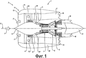
- фиг.1 представляет собой вид в осевом разрезе двухконтурного турбореактивного двигателя, к которому применяется изобретение;- figure 1 is a view in axial section of a dual-circuit turbojet engine to which the invention is applied;
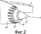
- фиг.2 представляет собой виды, выполненные в три четверти сзади, реактивных сопел турбореактивного двигателя, установленного под крылом и содержащего устройство согласно изобретению;- figure 2 is a view, made in three quarters of the rear, jet nozzles of a turbojet engine mounted under the wing and containing the device according to the invention;
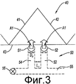
- фиг.3 изображает деталь шеврона, с которым связано средство выброса дополнительных струй согласно изобретению.- figure 3 depicts a detail of the chevron, which is associated with the means of ejection of additional jets according to the invention.
Описание варианта реализацииDescription of the implementation option
Турбореактивный двигатель 1, представленный на фиг.1, относится к двухконтурному и двухвальному типу, имеющему симметрию вращения вокруг оси X-X', с выбросом раздельных потоков. Известно, что этот турбореактивный двигатель 1 содержит внутри гондолы 2, служащей кожухом для его различных механизмов, воздухозаборник 3, через который поток входящего воздуха F может проникнуть для того, чтобы затем пройти через входной вентилятор 4. Этот поток воздуха F разделяется на два потока, соответственно первичный FP и вторичный FS, посредством промежуточного корпуса 5, край которого образует разделяющий носик.The turbojet engine 1 shown in FIG. 1 relates to a dual-circuit and twin-shaft type having rotation symmetry about an axis X-X ', with the release of separate flows. It is known that this turbojet engine 1 contains inside the
В последующем описании термины «передний» и «задний» относятся к осевым положениям вдоль продольной оси X-X' в направлении движения потока воздуха в турбореактивном двигателе 1.In the following description, the terms “front” and “rear” refer to axial positions along the longitudinal axis X-X ′ in the direction of air flow in the turbojet engine 1.
Вторичный поток FS проходит через ступень спрямляющего аппарата для того, чтобы затем быть выброшенным сзади турбореактивного двигателя через сопло 20 холодного или вторичного потока. Первичный поток FP последовательно проходит через ступень 6 компрессора низкого давления, ступень 7 компрессора высокого давления, камеру 8 сгорания, ступень 9 турбины высокого давления и ступень 10 турбины низкого давления для того, чтобы затем быть выброшенным за пределы турбореактивного двигателя через сопло 30 первичного потока.The secondary stream FS passes through the stage of the straightening apparatus in order to then be ejected behind the turbojet engine through the
Гондола 2 этого турбореактивного двигателя является кольцеобразной и расположена коаксиально вокруг продольной оси X-X'. Она позволяет направлять газовые потоки, образуемые турбореактивным двигателем, определяя внутренние и внешние линии аэродинамического течения для газовых потоков.The
Воздухозаборник 3, ось которого совпадает с осью X-X' вращения турбомашины I, содержит канал 11 воздухозаборника, а также конус 12 воздухозаборника. Последний позволяет осуществлять аэродинамическое направление и распределение общего потока F вокруг оси X-X'.The air intake 3, the axis of which coincides with the axis X-X 'of rotation of the turbomachine I, contains an
Сопло 30 первичного потока определяет вместе с выхлопным конусом 31 кольцевое пространство, через которое выбрасывается первичный поток FP.The
Сопло 20 вторичного потока определяет вместе с обтекателем первичного потока кольцевое пространство, через которое выбрасывается вторичный поток FS.The
Согласно примеру, изображенному на фиг.2, сквозь кольцевые пространства проходит пилон P, на котором подвешен двигатель.According to the example shown in figure 2, through the annular space passes the pylon P, on which the engine is suspended.
Как это известно, шум струи уменьшается за счет расположения элементов в виде треугольных или трапециевидных щитков сзади края одного или двух сопел, в данном случае на двух соплах согласно варианту реализации, представленному на фиг.2. Эти элементы 40, которые называются шевронами, крепятся их самой широкой стороной к соплу и проходят между передней плоскостью против участка выброса из сопла и задней плоскостью; предпочтительно, они образуют ненулевой угол с осью XX двигателя. В данном случае они все имеют одну и ту же форму и размеры, но они также могут быть различными вдоль периферии сопел. Свободные края шевронов ориентированы по сходящимся направлениям между передней плоскостью и задней плоскостью. Они прямолинейные или имеют также изогнутые части. Общая форма ребра обтекания, таким образом, представляет собой зубья пилы вдоль периферии сопла. Такое расположение способствует образованию турбулентных потоков в слое сдвига между первичными и вторичными потоками и между вторичным потоком и окружающим воздухом.As is known, the noise of the jet is reduced due to the arrangement of elements in the form of triangular or trapezoidal shields behind the edges of one or two nozzles, in this case, two nozzles according to the embodiment shown in FIG. 2. These
Эффективность шевронов улучшается, согласно изобретению, путем инициирования закручивания турбулентных потоков впереди относительно свободных краев 41 и 42 шевронов.The effectiveness of chevrons is improved, according to the invention, by initiating the swirling of turbulent flows in front of the relatively
Данный результат достигается путем впрыскивания в основную первичную или вторичную струю дополнительных газовых струй при помощи средств впрыскивания дополнительных газовых струй в устройстве 50 перед свободными краями 41 и 42, в частности перед передней плоскостью 43 шевронов. На фиг.3 изображен шеврон 40. В данном варианте реализации он имеет треугольную форму и жестко соединен с вторичным соплом 20 своим краем, расположенным в передней плоскости 43. Внутренняя сторона сопла 20, показанная от оси XX, просверлена двумя отверстиями 51 и 52, в которые выходят трубы 53 и 54, питаемые воздухом или отработавшим газом из коллектора 55. Часть труб, вытянутых вдоль обтекателя вторичного потока, показана на фиг.2. Питание из коллектора 55 управляется посредством клапана 56. Два отверстия 51 и 52 расположены перед передней плоскостью 43 и подают при работе аттенюатора шума струи дополнительные струи A1. Согласно этому представленному варианту реализации, каждая струя ориентирована по оси основной струи в направлении края. Предпочтительно, они наклонены в направлении оси двигателя под углом, возможно, равным углу наклона шеврона, с которым они связаны. Согласно другому варианту реализации, они могут иметь разную ориентацию, например, могут быть расходящимися. Их отклонение, а также их диаметр являются параметрами, которые следует учитывать. Это относится и к термодинамическим параметрам дополнительных струй, таким как давление, температура и расход.This result is achieved by injecting additional gas jets into the main primary or secondary stream by means of injecting additional gas jets in the
На фиг.3 изображены два отверстия для формирования двух дополнительных струй для шеврона, но в рамках изобретения также предполагается различное количество дополнительных струй и расположение, отличное от изображенного.Figure 3 shows two holes for the formation of two additional jets for the chevron, but in the framework of the invention also assumes a different number of additional jets and an arrangement different from that shown.
Во время взлета летательного аппарата хотят ввести в действие аттенюатор шума струи, управляют клапаном 56, устанавливая коллектор в сообщение с источником воздуха на уровне газогенератора, в частности. Дополнительные струи, истекающие из отверстий 51 и 52, приведут к образованию турбулентных потоков, которые за счет их положения будут усилены при прохождении свободных краев 41 и 42 шеврона. Турбулентные потоки противоположного вращения, создаваемые, таким образом, сзади шеврона, являются более энергетическими и позволяют обеспечить более хорошее смешение потоков, уменьшая излучение низких частот.During the take-off of the aircraft, they want to activate the jet noise attenuator, control the
Claims (6)
Applications Claiming Priority (3)
| Application Number | Priority Date | Filing Date | Title |
|---|---|---|---|
| FR1053756A FR2960028B1 (en) | 2010-05-12 | 2010-05-12 | DEVICE FOR ATTENUATING THE NOISE EMITTED BY THE JET OF A PROPULSION ENGINE OF AN AIRCRAFT. |
| FR1053756 | 2010-05-12 | ||
| PCT/FR2011/051060 WO2011141678A1 (en) | 2010-05-12 | 2011-05-11 | Device for reducing the noise emitted by the jet of an aircraft propulsion engine |
Publications (2)
| Publication Number | Publication Date |
|---|---|
| RU2012152095A RU2012152095A (en) | 2014-06-20 |
| RU2575503C2 true RU2575503C2 (en) | 2016-02-20 |
Family
ID=
Cited By (1)
| Publication number | Priority date | Publication date | Assignee | Title |
|---|---|---|---|---|
| RU2686535C1 (en) * | 2018-04-17 | 2019-04-29 | Федеральное государственное унитарное предприятие "Центральный институт авиационного моторостроения имени П.И. Баранова" | Flat output device of three-loop gas turbine engine of variable cycle |
Citations (3)
| Publication number | Priority date | Publication date | Assignee | Title |
|---|---|---|---|---|
| US7246481B2 (en) * | 2004-03-26 | 2007-07-24 | General Electric Company | Methods and apparatus for operating gas turbine engines |
| RU2310766C1 (en) * | 2006-02-06 | 2007-11-20 | Открытое акционерное общество "Авиадвигатель" | Herringrone reaction nozzle of gas-turbine engine |
| RU2379536C1 (en) * | 2005-10-19 | 2010-01-20 | Эрбюс Франс | Turbofan gas turbine engine with reduced jet noise |
Patent Citations (3)
| Publication number | Priority date | Publication date | Assignee | Title |
|---|---|---|---|---|
| US7246481B2 (en) * | 2004-03-26 | 2007-07-24 | General Electric Company | Methods and apparatus for operating gas turbine engines |
| RU2379536C1 (en) * | 2005-10-19 | 2010-01-20 | Эрбюс Франс | Turbofan gas turbine engine with reduced jet noise |
| RU2310766C1 (en) * | 2006-02-06 | 2007-11-20 | Открытое акционерное общество "Авиадвигатель" | Herringrone reaction nozzle of gas-turbine engine |
Cited By (1)
| Publication number | Priority date | Publication date | Assignee | Title |
|---|---|---|---|---|
| RU2686535C1 (en) * | 2018-04-17 | 2019-04-29 | Федеральное государственное унитарное предприятие "Центральный институт авиационного моторостроения имени П.И. Баранова" | Flat output device of three-loop gas turbine engine of variable cycle |
Similar Documents
| Publication | Publication Date | Title |
|---|---|---|
| RU2435057C2 (en) | Turbofan gas turbine engine with adjustable fan outlet guide vanes (versions) | |
| US7246481B2 (en) | Methods and apparatus for operating gas turbine engines | |
| US7921637B2 (en) | High bypass-ratio turbofan jet engine | |
| US9845159B2 (en) | Conjoined reverse core flow engine arrangement | |
| JP4855275B2 (en) | Core exhaust mixer with variable range for turbofan jet engines of supersonic aircraft | |
| US10829232B2 (en) | Aircraft comprising a propulsion assembly including a fan on the rear of the fuselage | |
| JP6378736B2 (en) | Compression cowl for jet engine exhaust | |
| US9758254B2 (en) | Jet noise suppressor | |
| RU2546347C2 (en) | Noise killer for turbojet nacelle equipped with moving herring-bone-like elements and nacelle therewith | |
| CN101523041A (en) | Jet engine nacelle for an aircraft and aircraft comprising such a nacelle | |
| US20120192543A1 (en) | Exhaust nozzle for a bypass airplane turbojet having a deployable secondary cover and a retractable central body | |
| US9422887B2 (en) | Device for reducing the noise emitted by the jet of an aircraft propulsion engine | |
| US20140130503A1 (en) | Turbofan engine with convergent - divergent exhaust nozzle | |
| US7412832B2 (en) | Method and apparatus for operating gas turbine engines | |
| WO2010144181A1 (en) | Gas turbine engine assembly and corresponding operating method | |
| US7845156B2 (en) | Turbofan exhaust system | |
| CN106988793B (en) | Nozzle assemblies for gas turbine engines | |
| US20040244357A1 (en) | Divergent chevron nozzle and method | |
| RU2575503C2 (en) | Gas exhaust nozzle and multiflow turbojet engine | |
| EP0528894A1 (en) | Variable cycle gas turbine engine for supersonic aircraft | |
| CN116696519A (en) | Infrared inhibitor and infrared inhibition method | |
| CN118361753A (en) | A dovetail support plate flame stabilizer for integrated afterburner | |
| RU169735U1 (en) | ADJUSTABLE MIXING DEVICE OF TURBO-REACTIVE TWO-CIRCUIT ENGINE | |
| JP2000291490A (en) | Thrust reservoir of specific contour for gas turbine engine and nozzle silencer with lobe |