RU2572646C2 - Radio-frequency shield for magnetic-resonance imaging comprising conductive coating as shielding material - Google Patents
Radio-frequency shield for magnetic-resonance imaging comprising conductive coating as shielding material Download PDFInfo
- Publication number
- RU2572646C2 RU2572646C2 RU2013112893/28A RU2013112893A RU2572646C2 RU 2572646 C2 RU2572646 C2 RU 2572646C2 RU 2013112893/28 A RU2013112893/28 A RU 2013112893/28A RU 2013112893 A RU2013112893 A RU 2013112893A RU 2572646 C2 RU2572646 C2 RU 2572646C2
- Authority
- RU
- Russia
- Prior art keywords
- radio
- gradient
- conductive coating
- screen
- frequency
- Prior art date
Links
Images


Classifications
-
- G—PHYSICS
- G01—MEASURING; TESTING
- G01R—MEASURING ELECTRIC VARIABLES; MEASURING MAGNETIC VARIABLES
- G01R33/00—Arrangements or instruments for measuring magnetic variables
- G01R33/20—Arrangements or instruments for measuring magnetic variables involving magnetic resonance
- G01R33/28—Details of apparatus provided for in groups G01R33/44 - G01R33/64
- G01R33/42—Screening
- G01R33/422—Screening of the radio frequency field
-
- C—CHEMISTRY; METALLURGY
- C25—ELECTROLYTIC OR ELECTROPHORETIC PROCESSES; APPARATUS THEREFOR
- C25D—PROCESSES FOR THE ELECTROLYTIC OR ELECTROPHORETIC PRODUCTION OF COATINGS; ELECTROFORMING; APPARATUS THEREFOR
- C25D15/00—Electrolytic or electrophoretic production of coatings containing embedded materials, e.g. particles, whiskers, wires
-
- G—PHYSICS
- G01—MEASURING; TESTING
- G01R—MEASURING ELECTRIC VARIABLES; MEASURING MAGNETIC VARIABLES
- G01R33/00—Arrangements or instruments for measuring magnetic variables
- G01R33/20—Arrangements or instruments for measuring magnetic variables involving magnetic resonance
- G01R33/44—Arrangements or instruments for measuring magnetic variables involving magnetic resonance using nuclear magnetic resonance [NMR]
- G01R33/48—NMR imaging systems
- G01R33/54—Signal processing systems, e.g. using pulse sequences ; Generation or control of pulse sequences; Operator console
- G01R33/56—Image enhancement or correction, e.g. subtraction or averaging techniques, e.g. improvement of signal-to-noise ratio and resolution
- G01R33/565—Correction of image distortions, e.g. due to magnetic field inhomogeneities
- G01R33/56518—Correction of image distortions, e.g. due to magnetic field inhomogeneities due to eddy currents, e.g. caused by switching of the gradient magnetic field
Abstract
Description
ОБЛАСТЬ ТЕХНИКИ, К КОТОРОЙ ОТНОСИТСЯ ИЗОБРЕТЕНИЕFIELD OF THE INVENTION
Изобретение относится к системе формирования магнитно-резонансных изображений, включающей в себя радиочастотный экран, содержащий проводящее покрытие в качестве экранирующего материала, а также к способу изготовления системы формирования магнитно-резонансных изображений.The invention relates to a system for the formation of magnetic resonance images, including a radio frequency screen containing a conductive coating as a shielding material, as well as to a method for manufacturing a system for forming a magnetic resonance image.
УРОВЕНЬ ТЕХНИКИBACKGROUND
Магнитно-резонансные методы формирования изображения, которые для формирования двумерных или трехмерных изображений используют взаимодействие между магнитным полем и спинами ядер, широко используются в настоящее время, особенно в области медицинской диагностики, так как для формирования изображений мягких тканей они во многих отношениях превосходят другие методы формирования изображений, не требуют ионизирующего излучения, и, как правило, неинвазивны.Magnetic resonance imaging methods, which use the interaction between the magnetic field and the spins of nuclei to form two-dimensional or three-dimensional images, are widely used at present, especially in the field of medical diagnostics, since they are superior in many respects to other imaging methods images that do not require ionizing radiation, and are usually non-invasive.
В соответствии с магнитно-резонансным методом в целом тело пациента или вообще объект, подлежащий изучению, расположен в сильном однородном магнитном поле B0, направление которого в то же время определяет ось, как правило, ось z системы координат, на которой основано измерение.According to the magnetic resonance method, the patient’s body as a whole or the object to be studied in general is located in a strong uniform magnetic field B0, the direction of which at the same time determines the axis, as a rule, the z axis of the coordinate system on which the measurement is based.
Магнитное поле создает различные энергетические уровни для отдельных ядерных спинов в зависимости от силы приложенного магнитного поля, которым спины могут быть возбуждены (спиновый резонанс), путем применения переменного электромагнитного поля (радиочастотное поле) определенной частоты, так называемой ларморовской частоты или магнитно-резонансной частоты. С макроскопической точки зрения распределение отдельных ядерных спинов дает общую намагниченность, которая может быть выведена из состояния равновесия путем применения электромагнитного импульса соответствующей частоты (радиочастотного импульса), в то время как магнитное поле проходит перпендикулярно оси z, так что намагниченность выполняет прецессионное движение вокруг оси z.The magnetic field creates various energy levels for individual nuclear spins depending on the strength of the applied magnetic field by which the spins can be excited (spin resonance), by applying an alternating electromagnetic field (radio frequency field) of a certain frequency, the so-called Larmor frequency or magnetic resonance frequency. From a macroscopic point of view, the distribution of individual nuclear spins gives a general magnetization, which can be removed from the equilibrium state by applying an electromagnetic pulse of the corresponding frequency (radio frequency pulse), while the magnetic field passes perpendicular to the z axis, so that the magnetization performs a precessional motion around the z axis .
Любое изменение намагниченности может быть обнаружено с помощью принимающих радиочастотных антенн, которые расположены и ориентированы в рассматриваемом объеме магнитно-резонансного устройства таким образом, что изменение намагниченности измеряется в направлении, перпендикулярном к оси z.Any change in the magnetization can be detected using the receiving RF antennas, which are located and oriented in the considered volume of the magnetic resonance device in such a way that the change in the magnetization is measured in a direction perpendicular to the z axis.
Для того чтобы реализовать пространственное разрешение в организме, изменяющиеся градиенты магнитного поля, направленные вдоль трех основных осей, накладываются на однородное магнитное поле, что приводит к линейной пространственной зависимости частоты спинового резонанса. Сигнал, получаемый приемными антеннами, содержит компоненты различных частот, которые могут быть связаны с различными положениями в организме.In order to realize spatial resolution in the body, changing magnetic field gradients directed along three main axes are superimposed on a uniform magnetic field, which leads to a linear spatial dependence of the frequency of spin resonance. The signal received by the receiving antennas contains components of different frequencies that can be associated with different positions in the body.
Данные сигнала, полученные с помощью приемных антенн, соответствуют пространственной частотной области и называются данными k-пространства. Данные k-пространства обычно включают в себя множество линий, полученных с помощью разного фазового кодирования. Каждая линия преобразуется в цифровую форму путем сбора нескольких образцов. Набор образцов данных k-пространства преобразуется в магнитно-резонансное изображение, например, с помощью преобразования Фурье.The signal data obtained using the receiving antennas correspond to the spatial frequency domain and are called k-space data. K-space data typically includes multiple lines obtained using different phase coding. Each line is digitized by collecting several samples. A set of k-space data samples is converted to a magnetic resonance image, for example, using the Fourier transform.
Одним из важных аспектов в формировании магнитно-резонансных изображений является эффективная защита с использованием РЧ (радиочастотных) щитов (или радиочастотных экранов) для экранирования градиентных катушек от вышеупомянутых радиочастотных полей. Есть два основных требования к конструкции радиочастотных экранов: первое требование состоит в том, что радиочастотный экран должен быть хорошо проводящим, чтобы действовать как экран для радиочастотных полей в мегагерцовом диапазоне, генерируемом радиочастотной антенной магнитно-резонансной системы. Однако предпочтительный хорошо проводящий радиочастотный экран, который эффективно блокирует радиосигналы радиочастотной антенны, действует в то же время как среда, в которой могут быть индуцированы вихревые токи благодаря изменениям градиентов магнитного поля в килогерцовом диапазоне, в котором эти вихревые токи вызывают существенное тепловыделение в радиочастотном экране. Таким образом, второе требование заключается в том, чтобы радиочастотный экран был способен эффективно подавлять развитие вихревых токов.One of the important aspects in the formation of magnetic resonance images is the effective protection using RF (radio frequency) shields (or radio frequency screens) to shield the gradient coils from the aforementioned radio frequency fields. There are two basic requirements for the design of RF screens: the first requirement is that the RF screen must be well conductive in order to act as a shield for RF fields in the megahertz range generated by the RF antenna of the magnetic resonance system. However, the preferred well-conducting radio-frequency shield that effectively blocks the radio signals of the radio-frequency antenna acts at the same time as the medium in which eddy currents can be induced due to changes in the magnetic field gradients in the kilohertz range in which these eddy currents cause significant heat generation in the radio-frequency screen. Thus, the second requirement is for the RF screen to be able to effectively suppress the development of eddy currents.
Однако хорошая радиочастотная защита требует материалов с высокой проводимостью, в то время как использование материалов с высокой проводимостью приводит к развитию нежелательных вихревых токов.However, good RF protection requires materials with high conductivity, while the use of materials with high conductivity leads to the development of unwanted eddy currents.
Для того чтобы разрешить этот конфликт, обычно используются щелевые радиочастотные экраны, в которых полоски радиочастотного экрана соединены конденсаторами для того, чтобы «закрыть» их для радиочастот. Эти конденсаторы могут быть либо дискретными компонентами, либо они также могут быть распределенными конденсаторами.In order to resolve this conflict, slotted RF screens are usually used in which the strips of the RF screen are connected by capacitors in order to “close” them to the radio frequencies. These capacitors can either be discrete components, or they can also be distributed capacitors.
Например, патентная заявка США №7230427В2 описывает магнитно-резонансное устройство с блоком радиочастотной антенны и блоком градиентных катушек, в котором магнитно-резонансное устройство включает радиочастотный экран, расположенный между блоком радиочастотной антенны и блоком градиентных катушек.For example, US Patent Application No. 7,230,427 B2 describes a magnetic resonance device with an RF antenna unit and a gradient coil unit, in which the magnetic resonance device includes an RF screen located between the RF antenna unit and the gradient coil unit.
Хотя разрезание радиочастотных экранов и соединение получившихся в результате полос конденсаторами дает хороший компромисс между высокой проводимостью для радиочастотного экранирования и подавлением вихревых токов, радиочастотные экраны, изготовленные таким образом, являются дорогими из-за процедуры резки и соединения полос емкостными мостами. Европейская патентная заявка EP0430104 упоминает радиочастотный экранирующий корпус, выполненный из проводящего слоя.Although cutting RF screens and connecting the resulting strips with capacitors provides a good compromise between high conductivity for RF shielding and suppression of eddy currents, RF screens made in this way are expensive due to the cutting and band connection capacitive bridges. European patent application EP0430104 mentions a radio frequency shielding housing made of a conductive layer.
Из всего вышесказанного легко понять, что имеется необходимость в усовершенствованном радиочастотном экране. Следовательно, целью настоящего изобретения является создание усовершенствованной системы формирования магнитно-резонансных изображений, содержащей улучшенный радиочастотный экран.From the foregoing, it is easy to understand that there is a need for an improved RF screen. Therefore, it is an object of the present invention to provide an improved magnetic resonance imaging system comprising an improved RF screen.
РАСКРЫТИЕ ИЗОБРЕТЕНИЯSUMMARY OF THE INVENTION
В соответствии с настоящим изобретением предлагается система формирования магнитно-резонансных изображений, включающая в себя главный магнит для создания равномерного, устойчивого магнитного поля в исследуемом объеме, и по меньшей мере одну радиочастотную антенну для передачи радиочастотных импульсов к исследуемому объему для возбуждения магнитного спинового резонанса. Кроме того, система включает в себя блок градиентных катушек, содержащий градиентные катушки для создания градиентных магнитных полей в исследуемом объеме. Система также содержит радиочастотный экран, расположенный между указанной радиочастотной антенной и указанными градиентными катушками в тех частях блока градиентных катушек, которые пространственно обращены к исследуемому объему (100) и покрыты проводящим покрытием (104, 110) для формирования радиочастотного экрана (104), который содержит экранирующий материал, адаптированный для подавления вихревых токов, индуцированных в экране указанными градиентными магнитными полями, и для экранирования градиентных катушек от радиочастотных полей, генерируемых радиочастотной антенной, при этом радиочастотный экран содержит проводящее покрытие в качестве экранирующего материала.In accordance with the present invention, there is provided a magnetic resonance imaging system comprising a main magnet for generating a uniform, stable magnetic field in a test volume, and at least one radio frequency antenna for transmitting radio frequency pulses to the test volume for exciting magnetic spin resonance. In addition, the system includes a block of gradient coils containing gradient coils for creating gradient magnetic fields in the test volume. The system also contains a radio frequency shield located between the specified radio frequency antenna and the indicated gradient coils in those parts of the block of gradient coils that are spatially facing the test volume (100) and are coated with a conductive coating (104, 110) to form a radio frequency screen (104), which contains shielding material adapted to suppress eddy currents induced in the screen by the indicated gradient magnetic fields, and to shield the gradient coils from radio frequency fields, g generated by the radio frequency antenna, wherein the radio frequency screen comprises a conductive coating as a shielding material.
Система формирования магнитно-резонансных изображений, содержащая радиочастотный экран, который содержит проводящее покрытие в качестве экранирующего материала, имеет то преимущество, что она может быть изготовлена простым и, следовательно, дешевым способом. Так как больше не требуется разрезать радиочастотный экран, не требуется и соединять полосы емкостными мостами, что таким образом облегчает изготовление соответствующего радиочастотного экрана и снижает затраты на производство.A magnetic resonance imaging system comprising a radio frequency screen that includes a conductive coating as a shielding material has the advantage that it can be manufactured in a simple and therefore cheap manner. Since it is no longer necessary to cut the radio-frequency shield, it is not necessary to connect the strips with capacitive bridges, which thus facilitates the manufacture of the corresponding radio-frequency shield and reduces production costs.
Хорошие характеристики проводящего покрытия в качестве экранирующего материала обусловлены его зернистой структурой, в которой присутствует как омический контакт между металлическими зернами, содержащимися в покрытии, так и емкостная связь между ними. Свойства проводящего покрытия таким образом можно варьировать путем изменения его состава, что обуславливает размер, форму, электрические свойства и плотность металлических зерен в покрытии. Предпочтительно, чтобы толщина проводящего покрытия находилась в пределах от 7 мкм до 25 мкм. Кроме того, в предпочтительном варианте осуществления поверхностное сопротивление проводящего покрытия находится между 0,01 и 0,75 Ом/квадрат/25 мкм. С таким тщательно подобранным поверхностным сопротивлением проводящего покрытия можно одновременно удовлетворить как требование хорошего радиочастотного экранирования градиентных катушек от радиочастотных полей, так и требование хорошего подавления вихревых токов.The good characteristics of the conductive coating as a shielding material are due to its granular structure, in which there is both an ohmic contact between the metal grains contained in the coating and a capacitive coupling between them. The properties of the conductive coating can thus be varied by changing its composition, which determines the size, shape, electrical properties and density of the metal grains in the coating. Preferably, the thickness of the conductive coating is in the range of 7 μm to 25 μm. In addition, in a preferred embodiment, the surface resistance of the conductive coating is between 0.01 and 0.75 Ohm / square / 25 μm. With such a carefully selected surface resistance of the conductive coating, it is possible to simultaneously satisfy both the requirement of good RF shielding of the gradient coils from RF fields and the requirement of good suppression of eddy currents.
В соответствии с вариантом осуществления изобретения проводящее покрытие содержит серебро и/или медь в качестве проводящего материала.According to an embodiment of the invention, the conductive coating comprises silver and / or copper as the conductive material.
В соответствии с еще одним вариантом осуществления изобретения части блока градиентных катушек, пространственно обращенные к исследуемому объему, покрыты проводящим покрытием для формирования радиочастотного экрана. Другими словами, в этом варианте осуществления не требуется дополнительной подложки для проводящего покрытия, вместо этого проводящее покрытие наносится непосредственно на блок градиентных катушек. Этот метод имеет несколько преимуществ: первое преимущество заключается в том, что в магнитно-резонансной системе не требуется никаких дополнительных компонентов для радиочастотного экранирования, которые надо было бы присоединять к магнитно-резонансной системе в качестве дополнительного радиочастотного экрана. Второе преимущество состоит в том, что некоторое количество тепла, генерируемого в проводящем покрытии вихревыми токами, рассеивается непосредственно в направлении блока градиентных катушек, который обычно включает в себя систему охлаждения градиентных катушек. Следовательно, эта система охлаждения градиентных катушек может быть использована для охлаждения одновременно и градиентных катушек, и радиочастотного экрана. Не требуется никакого дополнительного охлаждения радиочастотного экрана, что еще больше снижает затраты на производство систем формирования магнитно-резонансных изображений.In accordance with another embodiment of the invention, parts of the block of gradient coils spatially facing the test volume are coated with a conductive coating to form an RF screen. In other words, in this embodiment, no additional substrate is required for the conductive coating, instead, the conductive coating is applied directly to the block of gradient coils. This method has several advantages: the first advantage is that in the magnetic resonance system does not require any additional components for RF shielding, which would have to be connected to the magnetic resonance system as an additional RF screen. A second advantage is that some of the heat generated in the eddy current conductive coating is dissipated directly in the direction of the gradient coil unit, which typically includes a gradient coil cooling system. Therefore, this gradient coil cooling system can be used to cool both gradient coils and an RF screen simultaneously. No additional cooling of the radio-frequency screen is required, which further reduces the cost of manufacturing systems for the formation of magnetic resonance images.
Еще одним преимуществом этого варианта является то, что отсутствует зазор между радиочастотным экраном и блоком градиентных катушек, так как дополнительный радиочастотный экран не требуется. Это может быть использовано, например, для повышения эффективности радиочастотной катушки (например, катушки для тела) или увеличения отверстия для пациента, то есть для увеличения исследуемого объема.Another advantage of this option is that there is no gap between the RF screen and the gradient coil unit, since an additional RF screen is not required. This can be used, for example, to increase the efficiency of the radio frequency coil (for example, a body coil) or to increase the opening for the patient, that is, to increase the test volume.
В соответствии с вариантом осуществления изобретения части блока градиентных катушек, содержащие проводящее покрытие, находятся в прямом тепловом контакте с указанной системой охлаждения. Это позволяет отводить тепло в очень больших количествах от радиочастотного экрана к системе охлаждения градиентных катушек, которая, в свою очередь, позволяет обеспечить проводящее покрытие в качестве экранирующего материала с более высокой проводимостью и, следовательно, с гораздо лучшим экранированием градиентных катушек от радиочастотных полей. Более интенсивное образование вихревых токов и, следовательно, большее рассеивание тепла компенсируется с помощью прямого теплового контакта радиочастотного экрана с системой охлаждения градиентных катушек.According to an embodiment of the invention, parts of the gradient coil unit containing the conductive coating are in direct thermal contact with said cooling system. This allows heat to be removed in very large quantities from the RF screen to the gradient coil cooling system, which, in turn, allows the conductive coating to be provided as a shielding material with higher conductivity and, therefore, with much better shielding of the gradient coils from RF fields. A more intense formation of eddy currents and, therefore, greater heat dissipation is compensated by direct thermal contact of the RF screen with the cooling system of the gradient coils.
В соответствии с альтернативным вариантом осуществления изобретения радиочастотный экран представляет собой электрически изолирующую подложку, покрытую проводящим покрытием. Например, может быть использована пластина поликарбоната, которая может быть установлена на блок градиентных катушек вокруг радиочастотной антенны. Это имеет то преимущество, что радиочастотный экран может быть заменен простым и дешевым способом. Так, например, из-за износа радиочастотного экрана проводящее покрытие может быть частично удалено. В этом случае радиочастотный экран может быть легко восстановлен путем его простой замены на новый радиочастотный экран.According to an alternative embodiment of the invention, the RF screen is an electrically insulating substrate coated with a conductive coating. For example, a polycarbonate plate can be used that can be mounted on a block of gradient coils around an RF antenna. This has the advantage that the RF screen can be replaced in a simple and cheap way. So, for example, due to wear of the RF screen, the conductive coating may be partially removed. In this case, the RF screen can be easily restored by simply replacing it with a new RF screen.
В соответствии с вариантом осуществления изобретения подложка может быть непосредственно присоединена к блоку градиентных катушек. В одном варианте осуществления подложка изготовлена из электроизоляционного материала, который в то же время обладает свойством высокой теплопроводности. Примером такого материала может быть, например, нитрид алюминия или нитрид бора.According to an embodiment of the invention, the substrate can be directly attached to the gradient coil unit. In one embodiment, the substrate is made of an electrical insulating material, which at the same time has the property of high thermal conductivity. An example of such a material may be, for example, aluminum nitride or boron nitride.
Такая электроизолирующая, но в то же время теплопроводящая подложка имеет то преимущество, что она способна отводить тепло, генерируемое в проводящем покрытии, в направлении блока градиентных катушек. Таким образом, система охлаждения, имеющаяся в блоке градиентных катушек, опять может быть использована для эффективного отвода тепла от проводящего покрытия.Such an electrically insulating, but at the same time thermally conductive substrate has the advantage that it is able to remove the heat generated in the conductive coating in the direction of the block of gradient coils. Thus, the cooling system available in the block of gradient coils can again be used to effectively remove heat from the conductive coating.
В качестве альтернативы радиочастотный экран может быть снабжен системой воздушного охлаждения, которая находится в прямом тепловом контакте с подложкой.Alternatively, the radio frequency shield may be provided with an air cooling system that is in direct thermal contact with the substrate.
В предпочтительном варианте осуществления, независимо от теплопроводности подложки, радиочастотный экран может быть обращен своей покрытой стороной к градиентным катушкам. Это позволяет увеличить расстояние до самой радиочастотной катушки, что хорошо для ее чувствительности и эффективности. Следовательно, необходимость в высокой проводимости покрытия уменьшается. Радиочастотный экран по этому варианту осуществления может быть охлажден в направлении градиентных катушек либо воздухом, либо материалом текучего типа, например гелем, который может быть применен после того, как радиочастотный экран был присоединен к градиентным катушкам. Однако в целом охлаждающая среда, такая как воздух или гель, может быть применена между радиочастотным экраном и блоком градиентных катушек независимо от пространственной ориентации покрытия (по направлению к блоку градиентных катушек или от него) и не зависит от материала подложки.In a preferred embodiment, irrespective of the thermal conductivity of the substrate, the RF screen can face its gradient coils with its coated side. This allows you to increase the distance to the radio frequency coil itself, which is good for its sensitivity and efficiency. Therefore, the need for high conductivity of the coating is reduced. The radiofrequency shield of this embodiment can be cooled in the direction of the gradient coils with either air or a fluid type material, for example a gel, which can be applied after the radiofrequency shield has been attached to the gradient coils. However, in general, a cooling medium, such as air or gel, can be applied between the RF screen and the gradient coil block regardless of the spatial orientation of the coating (towards or from the gradient coil block) and is independent of the substrate material.
В другом аспекте изобретение относится к способу изготовления системы формирования магнитно-резонансных изображений, описанной выше, причем способ включает в себя нанесение проводящего покрытия путем применения методов распыления или гальванопластики. В обоих случаях соответствующие производственные процессы могут просто и надежно управляться, обеспечивая тем самым возможности производства систем формирования магнитно-резонансных изображений.In another aspect, the invention relates to a method for manufacturing the magnetic resonance imaging system described above, the method comprising applying a conductive coating by applying spraying methods or electroplating. In both cases, the corresponding production processes can be easily and reliably controlled, thereby providing the possibility of manufacturing systems for the formation of magnetic resonance images.
В случае гальванопластики, конечно, требуется первоначальное нанесение специального покрытия на электроизоляционные поверхности подложки, на которые должно быть нанесено проводящее покрытие. Однако такие методы хорошо известны в данной области техники.In the case of electroforming, of course, initial application of a special coating is required on the electrical insulating surfaces of the substrate, on which the conductive coating should be applied. However, such methods are well known in the art.
КРАТКОЕ ОПИСАНИЕ ЧЕРТЕЖЕЙBRIEF DESCRIPTION OF THE DRAWINGS
Прилагаемые чертежи раскрывают предпочтительные варианты осуществления изобретения. Следует понимать, однако, что чертежи представлены в целях иллюстрации, а не как определение границ изобретения. На чертежах:The accompanying drawings disclose preferred embodiments of the invention. It should be understood, however, that the drawings are presented for purposes of illustration and not as a definition of the scope of the invention. In the drawings:
Фиг.1 иллюстрирует схему магнитно-резонансного устройства в соответствии с изобретением,Figure 1 illustrates a diagram of a magnetic resonance device in accordance with the invention,
Фиг.2 иллюстрирует поперечное сечение магнитно-резонансной системы, включающей в себя радиочастотную антенну, блок градиентных катушек и радиочастотный экран,Figure 2 illustrates a cross section of a magnetic resonance system including a radio frequency antenna, a block of gradient coils and a radio frequency screen,
Фиг.3 показывает еще одну магнитно-резонансную систему в соответствии с изобретением,Figure 3 shows another magnetic resonance system in accordance with the invention,
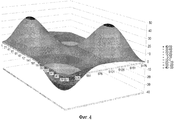
Фиг.4 иллюстрирует смоделированную схему вихревых токов в проводящем покрытии, действующем как радиочастотный экран.Figure 4 illustrates a simulated eddy current pattern in a conductive coating acting as an RF screen.
ОСУЩЕСТВЛЕНИЕ ИЗОБРЕТЕНИЯDETAILED DESCRIPTION OF THE INVENTION
Со ссылкой на Фиг.1 показана система 1 формирования магнитно-резонансных изображений. Система состоит из сверхпроводящих или резистивных основных магнитных катушек 2, таких, что существенно однородное, постоянное во времени основное магнитное поле B0 создается вдоль оси z через исследуемый объем.With reference to FIG. 1, a magnetic
Система магнитного резонанса применяет серии радиочастотных импульсов и меняющиеся градиенты магнитного поля, чтобы инвертировать или возбуждать ядерные магнитные спины, индуцировать магнитный резонанс, перефокусировать магнитный резонанс, манипулировать магнитным резонансом, пространственно или иным способом кодировать магнитный резонанс, насыщать спины и т.п., чтобы выполнять формирование магнитно-резонансных изображений.A magnetic resonance system applies a series of radio frequency pulses and varying magnetic field gradients to invert or excite nuclear magnetic spins, induce magnetic resonance, refocus magnetic resonance, manipulate magnetic resonance, spatially or otherwise encode magnetic resonance, saturate spins, etc., to perform the formation of magnetic resonance images.
Более конкретно, усилитель 3 градиентного импульса подает импульсы тока в избранные или все градиентные катушки 4, 5 и 6 вдоль осей х, у и z исследуемого объема. Радиочастотный передатчик 7 передает радиочастотные импульсы или импульсные пакеты через переключатель 8 передачи/приема на радиочастотную антенну 9, чтобы передать радиочастотные импульсы в исследуемый объем. Типичная последовательность формирования магнитно-резонансных изображений состоит из пакета последовательностей радиочастотных импульсов короткой продолжительности, которые берутся совместно друг с другом и любыми приложенными градиентами магнитного поля для достижения выбранной манипуляции ядерного магнитного резонанса. Радиочастотные импульсы используются для насыщения, возбуждения резонанса, инвертирования намагниченности, перефокусирования резонанса или манипуляции резонансом и выбора части тела 10, расположенного в исследуемом объеме. Магнитно-резонансные сигналы также могут быть приняты радиочастотной антенной 9.More specifically, the
Для генерации магнитно-резонансных изображений ограниченной области тела или объекта 10 в целом, например, с помощью параллельного формирования изображений набор локальных массивов радиочастотных катушек 11, 12 и 13 размещается поблизости от области, выбранной для сканирования. Массивы катушек 11, 12 и 13 могут быть использованы для получения магнитно-резонансных сигналов, индуцированных радиочастотным излучением, осуществляемым через радиочастотную антенну. Однако возможно также использовать массивы катушек 11, 12 и 13 для передачи радиочастотных сигналов к исследуемому объему.To generate magnetic resonance images of a limited area of the body or object 10 as a whole, for example, using parallel imaging, a set of local arrays of radio frequency coils 11, 12 and 13 are placed near the area selected for scanning. Arrays of
Полученные магнитно-резонансные сигналы принимаются радиочастотной антенной 9 и/или массивом радиочастотных катушек 11, 12 и 13 и демодулируются приемником 14, предпочтительно включающим предварительный усилитель (не показан). Приемник 14 соединен с радиочастотными катушками 9, 11, 12 и 13 через переключатель 8 передачи/приема.The obtained magnetic resonance signals are received by the
Компьютер 15 управляет усилителем 3 градиентного импульса и передатчиком 7, чтобы генерировать любую из множества последовательностей формирования изображений, таких как эхопланарное представление (echo planar imaging, EPI), эхообъемное представление, градиентное и спиновое эхопредставление, быстрое спиновое эхопредставление и т.п.
Для выбранной последовательности приемник 14 принимает одну или несколько линий магнитно-резонансных данных в быстрой последовательности после каждого радиочастотного возбуждающего импульса. Система 16 сбора данных выполняет аналогово-цифровое преобразование полученных сигналов и преобразует каждую линию магнитно-резонансных данных в цифровой формат, пригодный для дальнейшей обработки. В современных магнитно-резонансных устройствах система 16 сбора данных представляет собой отдельный компьютер, который специализируется на сборе исходных данных изображения.For the selected sequence, the
В конце концов цифровые данные исходного изображения восстанавливаются в графическое представление процессором 17 реконструкции, который применяет преобразование Фурье или другие соответствующие алгоритмы реконструкции. Магнитно-резонансное изображение может представлять собой плоский срез через пациента, массив параллельных плоских срезов, трехмерный объем и т.п. Затем изображение сохраняется в памяти изображений, где оно может быть доступно для преобразования срезов или других частей изображения в соответствующие форматы для формирования изображений, например, через видеомонитор 18, который обеспечивает воспринимаемое человеком отображение результирующего магнитно-резонансного изображения.In the end, the digital data of the original image is restored to a graphical representation by the
На Фиг.1 не показан радиочастотный экран, расположенный между радиочастотной антенной 9 и градиентными катушками 4, 5 и 6. Этот радиочастотный экран будет теперь описан более подробно со ссылкой на Фиг.2 и Фиг.3.Figure 1 does not show an RF screen located between the
Фиг.2 иллюстрирует схему расположения блока градиентных катушек, содержащих градиентную катушку 6, например градиентную катушку оси z магнитно-резонансной системы 1 на Фиг.1, радиочастотный экран 104 и по меньшей мере одну радиочастотную антенну 9 для передачи радиочастотных импульсов к исследуемому объему, обозначенному цифрой 100. Объект для сканирования обозначен цифрой 10.FIG. 2 illustrates an arrangement of a block of gradient coils containing a
В варианте осуществления, показанном на Фиг.2, градиентная катушка 6 включает в себя систему 102 охлаждения, например жидкостную систему охлаждения, где в поперечном сечении, показанном на Фиг.2, элементы, обозначенные цифрами 102, иллюстрируют поперечные сечения охлаждающих каналов, через которые может течь охлаждающая среда.In the embodiment shown in FIG. 2, the
Радиочастотный экран 104 расположен между радиочастотной антенной 9 и градиентной катушкой 6, где радиочастотный экран содержит экранирующий материал, адаптированный для подавления вихревых токов, индуцируемых в экране изменениями градиентных магнитных полей градиентной катушки 6, а также для экранирования градиентной катушки 6 от радиочастотных полей, порождаемых радиочастотной антенной 9. Радиочастотный экран 104 представляет собой проводящее покрытие поверхностей градиентной катушки 6, обращенных к исследуемому объему 100. Таким образом, прокладки между антенной 9 и радиочастотным экраном 104 больше не требуются.An
В альтернативном варианте осуществления, показанном на Фиг.3, радиочастотный экран 104 содержит электрически непроводящую подложку 106, которая является основой для проводящего покрытия 110, служащего экранирующим материалом. Таким образом, в варианте осуществления, показанном на Фиг.2, радиочастотный экран является проводящим покрытием, непосредственно нанесенным на градиентную катушку 6, в то время как в варианте осуществления, показанном на Фиг.3, радиочастотный экран состоит из сочетания подложки 106 и покрытия 110, которое наносится на подложку 106. Однако, как уже упоминалось выше, в альтернативном варианте осуществления радиочастотный экран может быть обращен покрытием 110 к градиентной катушке 6.In the alternative embodiment shown in FIG. 3, the
Для того чтобы обеспечить достаточный отвод тепла от покрытия 110, на Фиг.3 может быть обеспечена дополнительная система 108 охлаждения, где обозначенные элементы 108 могут, например, иллюстрировать сечения труб, через которые может протекать воздух с целью отвода тепла. Однако, как описано выше, в том случае, если электроизоляционный материал 106 обладает хорошей теплопроводностью, отвод тепла от покрытия 110 также может быть выполнен через подложку 106 к системе 102 охлаждения градиентной катушки 6 - в этом случае предпочтительно, чтобы подложка 106 прикреплялась непосредственно к градиентной катушке 6.In order to ensure sufficient heat removal from the
Несмотря на то что на Фиг.2 и Фиг.3 показана только градиентная катушка 6, другие части блока градиентных катушек также могут быть использованы для нанесения проводящего покрытия в качестве экранирующего материала или для покрытия подложкой, на которую наносится проводящее покрытие. В то время как термин "градиентная катушка" обозначает только градиентную катушку саму по себе, термин "блок градиентных катушек" обозначает устройство, которое физически содержит в себе отдельные градиентные катушки, а также соответствующие электронные компоненты, необходимые для управления отдельными градиентными катушками.Although
Фиг.4 является смоделированной схемой вихревых токов в проводящем покрытии радиочастотного экрана в соответствии с изобретением.Figure 4 is a simulated eddy current pattern in a conductive coating of an RF screen in accordance with the invention.
Моделирование, изображенное на Фиг.4, было выполнено для градиентной катушки оси х. Картина индуцированных токов в радиочастотном экране напоминает картину токов самой градиентной катушки, но с гораздо меньшей интенсивностью. Вихревые токи в радиочастотном экране, как предполагается, образуются вследствие градиента по оси х величиной 100 Тл/м/с. Картина токов изображена как функция потока в проводящем покрытии, развернутом на плоской пластине.The simulation shown in FIG. 4 was performed for the x-axis gradient coil. The picture of the induced currents in the RF screen resembles the picture of the currents of the gradient coil itself, but with much lower intensity. Eddy currents in the RF screen are assumed to be generated due to the x-axis gradient of 100 T / m / s. The current pattern is depicted as a function of flow in a conductive coating deployed on a flat plate.
Важным аспектом изобретения является выбор подходящей толщины и типа покрытия для того, чтобы радиочастотный экран был достаточно прозрачным для градиентных полей, частоты которых находятся в килогерцовом диапазоне, и чтобы радиочастотный экран был одновременно существенно непрозрачным для радиочастотных полей, частоты которых находятся в мегагерцовом диапазоне.An important aspect of the invention is the selection of a suitable thickness and type of coating so that the RF screen is transparent enough for gradient fields whose frequencies are in the kilohertz range, and that the RF screen is simultaneously substantially opaque for radio frequency fields whose frequencies are in the megahertz range.
Рассеяние в проводящем покрытии радиочастотного экрана без щелей может быть рассчитано следующим образом: в первую очередь следует учитывать сопротивление проводящего слоя. Сопротивление может быть определено как поверхностное сопротивление, выраженное в Ом/квадрат/25 мкм, что является сопротивлением между двумя противоположными сторонами квадратной поверхности толщиной 25 мкм. Соотношение между сопротивлением и поверхностным сопротивлением выглядит какScattering in a conductive coating of an RF screen without gaps can be calculated as follows: first of all, the resistance of the conductive layer should be taken into account. Resistance can be defined as surface resistance, expressed in ohms / square / 25 microns, which is the resistance between two opposite sides of a square surface with a thickness of 25 microns. The relationship between resistance and surface resistance looks like
![]()
![]()
так чтоso that
ρ=Rsqdρ = R sq d
Типичное серебряное покрытие, используемое в настоящем изобретении, имеет поверхностное сопротивление 0,015 Ом/квадрат/25 мкм или удельное сопротивление 37,5 мкОм·см, что сопоставимо с характеристиками нержавеющей стали. Толщина покрытия на практике составляет от 7 до 25 мкм. Если предположить, что толщина слоя 15 мкм, то можно показать, что рассеяние, вызванное градиентными колебаниями, является доминирующим механизмом нагрева. Для градиентной катушки, работающей с высокой скоростью нарастания напряжения, значение 100 Тл/м/с может быть усреднено по продолжительности сканирования. Составляющая поля, перпендикулярная к радиочастотному экрану, создает вихревые токи, которые вызывают диссипацию.A typical silver coating used in the present invention has a surface resistance of 0.015 Ohm / square / 25 μm or a specific resistance of 37.5 μOhm · cm, which is comparable with the characteristics of stainless steel. The coating thickness in practice is from 7 to 25 microns. Assuming a layer thickness of 15 μm, it can be shown that scattering due to gradient oscillations is the dominant heating mechanism. For a gradient coil operating at a high slew rate, a value of 100 T / m / s can be averaged over the duration of the scan. The field component perpendicular to the RF screen creates eddy currents that cause dissipation.
Следует отметить, что диссипация около 1000 Вт в радиочастотном экране является высокой. Однако это не является желательным, даже если тепло может быть отведено через систему охлаждения градиентной катушки. Причина в том, что кроме нагрева вихревые токи могут вызвать нежелательные электромагнитные поля ошибки, которые влияют на качество полученных магнитно-резонансных изображений и отнимают дополнительную мощность у градиентного усилителя. Для того чтобы получить более приемлемую диссипацию, сопоставимую с современными радиочастотными экранами, желательный уровень диссипации должен составлять около 250 Вт или меньше. Рассеиваемая мощность растет с ростом d/р (d - толщина слоя, а р - поверхностное сопротивление), так что нагрев может быть снижен до приемлемого уровня путем использования проводящего слоя с более низкой проводимостью (т.е. с более высоким поверхностным сопротивлением).It should be noted that the dissipation of about 1000 watts in the RF screen is high. However, this is not desirable, even if heat can be removed through the cooling coil of the gradient coil. The reason is that, in addition to heating, eddy currents can cause undesirable electromagnetic fields of error, which affect the quality of the obtained magnetic resonance images and take away additional power from the gradient amplifier. In order to obtain a more acceptable dissipation comparable to modern RF screens, the desired dissipation level should be about 250 W or less. The power dissipation increases with d / p (d is the layer thickness and p is the surface resistance), so that the heating can be reduced to an acceptable level by using a conductive layer with lower conductivity (i.e. with higher surface resistance).
Например, в качестве проводящего материала серебро может быть заменено на медь, которая также делает проводящий слой менее дорогим. Тем не менее, следует отметить, что проводимость проводящего слоя меньше зависит от выбора материала (например, серебро или медь), чем от концентрации, формы и размера металлических зерен в покрытии.For example, as a conductive material, silver can be replaced with copper, which also makes the conductive layer less expensive. However, it should be noted that the conductivity of the conductive layer is less dependent on the choice of material (for example, silver or copper) than on the concentration, shape and size of the metal grains in the coating.
Кроме того, может быть использован тонкий слой, предпочтительно в диапазоне толщины слоя от 7 до 25 мкм. Наконец, могут быть применены простые разрезы, что, однако, не является предпочтительным, так как это приводит к более сложному рисунку и требует использования конденсаторов для создания емкостных мостов между полосками.In addition, a thin layer can be used, preferably in the range of the layer thickness from 7 to 25 microns. Finally, simple cuts can be applied, which, however, is not preferable, since this leads to a more complex pattern and requires the use of capacitors to create capacitive bridges between the strips.
Правильный выбор проводящего материала и толщины слоя обеспечивает улучшение в 100 раз по сравнению с известными решениями радиочастотных экранов, так что тепловыделение может быть сведено к действительно незначительному уровню. Это является принципиальной разницей между предлагаемым решением и обычными решениями, где радиочастотный экран изготовлен из металлической фольги. Использование металлической фольги всегда приводит к режиму сильной диссипации, что требует значительных усилий для охлаждения, а также к связанным с этим ранее упомянутым недостаткам. Это показывает, что существует принципиальная разница между использованием металлических листов и использованием проводящего слоя.The right choice of conductive material and layer thickness provides a 100-fold improvement over the known solutions of RF screens, so that heat generation can be reduced to a really insignificant level. This is the fundamental difference between the proposed solution and conventional solutions, where the RF screen is made of metal foil. The use of metal foil always leads to a regime of strong dissipation, which requires considerable effort for cooling, as well as to the previously mentioned disadvantages. This shows that there is a fundamental difference between the use of metal sheets and the use of a conductive layer.
Охлаждение магнита также может индуцировать токи в радиочастотном экране, но это влияние незначительно. Тот факт, что градиентная система может легко генерировать 100 Тл/с в непрерывном режиме у радиочастотного экрана, в то время как охлаждение магнита дает только 2 Тл/с в течение всего лишь нескольких секунд, означает, что охлаждение не является поводом для беспокойства. Фактический расчет тепла, индуцированного системой охлаждения в радиочастотном экране в соответствии с изобретением, дает лишь небольшое число, например 20 Дж, для системы охлаждения магнита в 3 Тл и радиочастотного экрана, покрытого слоем серебра толщиной 15 мкм.Magnet cooling can also induce currents in an RF screen, but this effect is negligible. The fact that the gradient system can easily generate 100 T / s in continuous mode at the RF screen, while cooling the magnet gives only 2 T / s in just a few seconds, means that cooling is not a cause for concern. The actual calculation of the heat induced by the cooling system in the RF screen in accordance with the invention gives only a small number, for example 20 J, for the cooling system of a 3 T magnet and RF screen coated with a 15 micron silver layer.
Claims (14)
главный магнит (2) для создания равномерного, устойчивого магнитного поля в исследуемом объеме,
по меньшей мере одну радиочастотную антенну (9) для передачи радиочастотных импульсов к исследуемому объему для возбуждения магнитного спинового резонанса,
блок градиентных катушек, содержащий градиентные катушки (4, 5, 6) для создания градиентных магнитных полей в исследуемом объеме (100),
радиочастотный экран (104), расположенный между указанной радиочастотной антенной (9) и указанными градиентными катушками (4, 5, 6) в тех частях блока градиентных катушек, которые пространственно обращены к исследуемому объему (100) и покрыты проводящим покрытием (104, 110) для формирования радиочастотного экрана (104), причем радиочастотный экран (104) содержит экранирующий материал, адаптированный для подавления вихревых токов, индуцированных в экране указанными градиентными магнитными полями, и для экранирования градиентных катушек (4, 5, 6) от радиочастотных полей, порождаемых радиочастотной антенной (9), при этом радиочастотный экран содержит проводящее покрытие (104, 110) в качестве экранирующего материала.1. System (1) for the formation of magnetic resonance images, including:
the main magnet (2) to create a uniform, stable magnetic field in the investigated volume,
at least one radio frequency antenna (9) for transmitting radio frequency pulses to the test volume for exciting magnetic spin resonance,
a block of gradient coils containing gradient coils (4, 5, 6) to create gradient magnetic fields in the test volume (100),
a radiofrequency shield (104) located between the indicated radiofrequency antenna (9) and the indicated gradient coils (4, 5, 6) in those parts of the block of gradient coils that are spatially facing the test volume (100) and are coated with a conductive coating (104, 110) for forming an RF screen (104), wherein the RF screen (104) contains shielding material adapted to suppress eddy currents induced in the screen by said gradient magnetic fields, and to shield the gradient coils (4, 5, 6) from the radio frequency of electromagnetic fields generated by the radio-frequency antenna (9), while the radio-frequency screen contains a conductive coating (104, 110) as a shielding material.
Applications Claiming Priority (3)
| Application Number | Priority Date | Filing Date | Title |
|---|---|---|---|
| EP10173946 | 2010-08-25 | ||
| EP10173946.4 | 2010-08-25 | ||
| PCT/IB2011/053658 WO2012025860A1 (en) | 2010-08-25 | 2011-08-19 | Rf shield for mri comprising conductive coating as shielding material |
Publications (2)
| Publication Number | Publication Date |
|---|---|
| RU2013112893A RU2013112893A (en) | 2014-09-27 |
| RU2572646C2 true RU2572646C2 (en) | 2016-01-20 |
Family
ID=44645159
Family Applications (1)
| Application Number | Title | Priority Date | Filing Date |
|---|---|---|---|
| RU2013112893/28A RU2572646C2 (en) | 2010-08-25 | 2011-08-19 | Radio-frequency shield for magnetic-resonance imaging comprising conductive coating as shielding material |
Country Status (6)
| Country | Link |
|---|---|
| US (1) | US9417301B2 (en) |
| EP (1) | EP2609443A1 (en) |
| JP (1) | JP5961612B2 (en) |
| CN (1) | CN103069295B (en) |
| RU (1) | RU2572646C2 (en) |
| WO (1) | WO2012025860A1 (en) |
Families Citing this family (6)
| Publication number | Priority date | Publication date | Assignee | Title |
|---|---|---|---|---|
| JP5961612B2 (en) * | 2010-08-25 | 2016-08-02 | コーニンクレッカ フィリップス エヌ ヴェKoninklijke Philips N.V. | RF shield for MRI with conductive coating as shielding material |
| US9116215B2 (en) * | 2013-01-09 | 2015-08-25 | General Electric Company | Composite RF shield and method of making same |
| CA2960189C (en) * | 2014-09-05 | 2021-11-23 | Hyperfine Research, Inc. | Low field magnetic resonance imaging methods and apparatus |
| DE202016104835U1 (en) * | 2016-09-01 | 2017-12-06 | Anita Silvia Zwerger-Schuster | Device for performing EMC test measurements |
| DE102016224357A1 (en) * | 2016-12-07 | 2018-04-19 | Siemens Healthcare Gmbh | Medical imaging device with RF screen |
| WO2020155137A1 (en) | 2019-02-02 | 2020-08-06 | Shanghai United Imaging Healthcare Co., Ltd. | Radiation therapy system and method |
Family Cites Families (30)
| Publication number | Priority date | Publication date | Assignee | Title |
|---|---|---|---|---|
| JPS63122442A (en) * | 1986-11-12 | 1988-05-26 | 株式会社東芝 | Magnetic resonance imaging apparatus |
| JPS63246437A (en) | 1987-04-01 | 1988-10-13 | Mazda Motor Corp | Air fuel ratio control device for engine |
| JPH0295347A (en) | 1988-09-30 | 1990-04-06 | Toshiba Corp | Magnetic resonance imaging device |
| JP2823278B2 (en) | 1989-11-28 | 1998-11-11 | 株式会社東芝 | Magnetic resonance imaging equipment |
| JP3092106B2 (en) * | 1990-03-05 | 2000-09-25 | 株式会社日立メディコ | Magnetic resonance imaging equipment |
| US5243286A (en) * | 1990-06-06 | 1993-09-07 | Advanced Nmr Systems, Inc. | Split shield for magnetic resonance imaging |
| US5304932A (en) | 1990-11-05 | 1994-04-19 | The Regents Of The University Of California | Apparatus and method for shielding MRI RF antennae from the effect of surrounding objects |
| JPH05237071A (en) | 1991-05-13 | 1993-09-17 | Yokogawa Medical Syst Ltd | Manufacture of gradient coil for nmr imaging apparatus |
| US5349297A (en) * | 1992-03-27 | 1994-09-20 | Picker International Inc. | Combined self shielded gradient coil and shimset |
| AU4374993A (en) * | 1992-07-10 | 1994-01-31 | Doty Scientific, Inc. | Solenoidal, octopolar, transverse gradient coils |
| DE4232884C2 (en) | 1992-09-30 | 1997-10-16 | Siemens Ag | Antenna arrangement for a nuclear magnetic resonance device |
| US5886596A (en) | 1993-08-06 | 1999-03-23 | Uab Research Foundation | Radio frequency volume coils for imaging and spectroscopy |
| FI103632B (en) * | 1994-06-16 | 1999-07-30 | Nokia Mobile Phones Ltd | Rf protection |
| US5539314A (en) * | 1994-12-01 | 1996-07-23 | The Regents Of The University Of California | RF shield for four-post vertical field magnet used for MRI |
| JPH08322815A (en) * | 1995-05-31 | 1996-12-10 | Shimadzu Corp | Mri equipment |
| US5760584A (en) * | 1996-08-16 | 1998-06-02 | General Electric Company | Shield for MR system RF coil provided with multiple capacitive channels for RF current flow |
| US6011394A (en) * | 1997-08-07 | 2000-01-04 | Picker International, Inc. | Self-shielded gradient coil assembly and method of manufacturing the same |
| JPH1176192A (en) * | 1997-09-10 | 1999-03-23 | Ge Yokogawa Medical Syst Ltd | Rf shielding plate and magnetic resonance imaging |
| US6954068B1 (en) * | 2000-01-21 | 2005-10-11 | Kabushiki Kaisha Toshiba | Magnetic resonance imaging apparatus |
| US20020073717A1 (en) * | 2000-12-19 | 2002-06-20 | Dean David E. | MR scanner including liquid cooled RF coil and method |
| US6593744B2 (en) | 2001-11-20 | 2003-07-15 | Koninklijke Philips Electronics, N.V. | Multi-channel RF cable trap for magnetic resonance apparatus |
| US6818291B2 (en) | 2002-08-17 | 2004-11-16 | 3M Innovative Properties Company | Durable transparent EMI shielding film |
| DE10354228B3 (en) | 2003-11-20 | 2005-09-22 | Siemens Ag | A gradient coil radio frequency antenna unit and a magnetic resonance apparatus having a gradient coil radio frequency antenna unit |
| US7102350B2 (en) | 2004-06-30 | 2006-09-05 | General Electric Company | Shielding apparatus for magnetic resonance imaging |
| DE102004040062B3 (en) | 2004-08-18 | 2006-04-27 | Siemens Ag | Magnetic resonance apparatus with an HF antenna unit and a gradient coil unit |
| DE102005033989B4 (en) * | 2005-07-21 | 2008-07-10 | Bruker Biospin Ag | Nuclear magnetic resonance apparatus with Gradientenabschirmanordnung with reduced coupling to the resonator system |
| US7489132B2 (en) * | 2006-12-15 | 2009-02-10 | General Electric Company | Enhanced heat transfer in MRI gradient coils with phase-change materials |
| US7511502B2 (en) * | 2007-01-05 | 2009-03-31 | Kabushiki Kaisha Toshiba | Magnetic resonance imaging apparatus |
| JP2008183397A (en) * | 2007-01-05 | 2008-08-14 | Toshiba Corp | Magnetic resonance imaging apparatus |
| JP5961612B2 (en) * | 2010-08-25 | 2016-08-02 | コーニンクレッカ フィリップス エヌ ヴェKoninklijke Philips N.V. | RF shield for MRI with conductive coating as shielding material |
-
2011
- 2011-08-19 JP JP2013525391A patent/JP5961612B2/en active Active
- 2011-08-19 CN CN201180041003.4A patent/CN103069295B/en active Active
- 2011-08-19 US US13/816,512 patent/US9417301B2/en active Active
- 2011-08-19 RU RU2013112893/28A patent/RU2572646C2/en not_active IP Right Cessation
- 2011-08-19 EP EP11755143.2A patent/EP2609443A1/en not_active Ceased
- 2011-08-19 WO PCT/IB2011/053658 patent/WO2012025860A1/en active Application Filing
Also Published As
| Publication number | Publication date |
|---|---|
| RU2013112893A (en) | 2014-09-27 |
| JP2013541357A (en) | 2013-11-14 |
| CN103069295B (en) | 2016-06-22 |
| EP2609443A1 (en) | 2013-07-03 |
| WO2012025860A1 (en) | 2012-03-01 |
| JP5961612B2 (en) | 2016-08-02 |
| CN103069295A (en) | 2013-04-24 |
| US20130207659A1 (en) | 2013-08-15 |
| US9417301B2 (en) | 2016-08-16 |
Similar Documents
| Publication | Publication Date | Title |
|---|---|---|
| RU2572646C2 (en) | Radio-frequency shield for magnetic-resonance imaging comprising conductive coating as shielding material | |
| Shajan et al. | A 16‐channel dual‐row transmit array in combination with a 31‐element receive array for human brain imaging at 9.4 T | |
| Metzger et al. | Local B1+ shimming for prostate imaging with transceiver arrays at 7T based on subject‐dependent transmit phase measurements | |
| Wiggins et al. | 96‐Channel receive‐only head coil for 3 Tesla: design optimization and evaluation | |
| US8525116B2 (en) | MR/PET imaging systems | |
| EP0629875B1 (en) | Magnetic resonance gradient coil and RF screen | |
| Wiggins et al. | Eight‐channel phased array coil and detunable TEM volume coil for 7 T brain imaging | |
| US8203342B2 (en) | Nuclear magnetic resonance imaging system and coil unit | |
| JP2005324028A (en) | Multi-turn element rf coil array for multiple channel mri | |
| Algarin et al. | Analysis of the resolution of split-ring metamaterial lenses with application in parallel magnetic resonance imaging | |
| JP7271765B2 (en) | RF coil device and RF shield device for different MRI modes | |
| EP2345906A1 (en) | RF antenna for a hybrid MRI/PET or MRI/HIFU system | |
| Alt et al. | Coaxial waveguide MRI | |
| Libove et al. | Resolution and signal-to-noise relationships in NMR imaging in the human body | |
| Wang et al. | A radially interleaved sodium and proton coil array for brain MRI at 7 T | |
| Shajan et al. | Rat brain MRI at 16.4 T using a capacitively tunable patch antenna in combination with a receive array | |
| Woo et al. | Extended monopole antenna array with individual shield (EMAS) coil: An improved monopole antenna design for brain imaging at 7 tesla MRI | |
| JP2003024302A (en) | Long wave thermal radiation shield | |
| US7692426B2 (en) | Magnetic resonance apparatus with a superconducting basic field magnet with an electrically conductive coating on the outer vacuum chamber | |
| CN109073719A (en) | Magnetic resonance emission shielding and shielded main magnet | |
| EP2588877A1 (en) | Cooled mr coil arrangement | |
| US9134390B2 (en) | Magnetic resonance local coil | |
| Van Helvoort et al. | Frequency-dependent shielding of electronics inside an MRI system | |
| Ono et al. | Experimental investigation of RF magnetic field homogeneity in a bridged loop‐gap resonator | |
| US10788373B2 (en) | Imaging device with loop bolometer array and related methods |
Legal Events
| Date | Code | Title | Description |
|---|---|---|---|
| MM4A | The patent is invalid due to non-payment of fees |
Effective date: 20160820 |