RU2572591C1 - Controller of ice with supercharging - Google Patents
Controller of ice with supercharging Download PDFInfo
- Publication number
- RU2572591C1 RU2572591C1 RU2014138030/07A RU2014138030A RU2572591C1 RU 2572591 C1 RU2572591 C1 RU 2572591C1 RU 2014138030/07 A RU2014138030/07 A RU 2014138030/07A RU 2014138030 A RU2014138030 A RU 2014138030A RU 2572591 C1 RU2572591 C1 RU 2572591C1
- Authority
- RU
- Russia
- Prior art keywords
- fuel
- cylinder
- ignition
- fuel supply
- abnormal combustion
- Prior art date
Links
Images

Classifications
-
- F—MECHANICAL ENGINEERING; LIGHTING; HEATING; WEAPONS; BLASTING
- F02—COMBUSTION ENGINES; HOT-GAS OR COMBUSTION-PRODUCT ENGINE PLANTS
- F02P—IGNITION, OTHER THAN COMPRESSION IGNITION, FOR INTERNAL-COMBUSTION ENGINES; TESTING OF IGNITION TIMING IN COMPRESSION-IGNITION ENGINES
- F02P5/00—Advancing or retarding ignition; Control therefor
- F02P5/04—Advancing or retarding ignition; Control therefor automatically, as a function of the working conditions of the engine or vehicle or of the atmospheric conditions
- F02P5/045—Advancing or retarding ignition; Control therefor automatically, as a function of the working conditions of the engine or vehicle or of the atmospheric conditions combined with electronic control of other engine functions, e.g. fuel injection
-
- F—MECHANICAL ENGINEERING; LIGHTING; HEATING; WEAPONS; BLASTING
- F02—COMBUSTION ENGINES; HOT-GAS OR COMBUSTION-PRODUCT ENGINE PLANTS
- F02D—CONTROLLING COMBUSTION ENGINES
- F02D41/00—Electrical control of supply of combustible mixture or its constituents
- F02D41/008—Controlling each cylinder individually
- F02D41/0087—Selective cylinder activation, i.e. partial cylinder operation
-
- F—MECHANICAL ENGINEERING; LIGHTING; HEATING; WEAPONS; BLASTING
- F02—COMBUSTION ENGINES; HOT-GAS OR COMBUSTION-PRODUCT ENGINE PLANTS
- F02D—CONTROLLING COMBUSTION ENGINES
- F02D41/00—Electrical control of supply of combustible mixture or its constituents
- F02D41/0002—Controlling intake air
- F02D41/0007—Controlling intake air for control of turbo-charged or super-charged engines
-
- F—MECHANICAL ENGINEERING; LIGHTING; HEATING; WEAPONS; BLASTING
- F02—COMBUSTION ENGINES; HOT-GAS OR COMBUSTION-PRODUCT ENGINE PLANTS
- F02D—CONTROLLING COMBUSTION ENGINES
- F02D41/00—Electrical control of supply of combustible mixture or its constituents
- F02D41/22—Safety or indicating devices for abnormal conditions
-
- F—MECHANICAL ENGINEERING; LIGHTING; HEATING; WEAPONS; BLASTING
- F02—COMBUSTION ENGINES; HOT-GAS OR COMBUSTION-PRODUCT ENGINE PLANTS
- F02P—IGNITION, OTHER THAN COMPRESSION IGNITION, FOR INTERNAL-COMBUSTION ENGINES; TESTING OF IGNITION TIMING IN COMPRESSION-IGNITION ENGINES
- F02P5/00—Advancing or retarding ignition; Control therefor
- F02P5/04—Advancing or retarding ignition; Control therefor automatically, as a function of the working conditions of the engine or vehicle or of the atmospheric conditions
- F02P5/145—Advancing or retarding ignition; Control therefor automatically, as a function of the working conditions of the engine or vehicle or of the atmospheric conditions using electrical means
- F02P5/15—Digital data processing
- F02P5/1502—Digital data processing using one central computing unit
- F02P5/1516—Digital data processing using one central computing unit with means relating to exhaust gas recirculation, e.g. turbo
-
- F—MECHANICAL ENGINEERING; LIGHTING; HEATING; WEAPONS; BLASTING
- F02—COMBUSTION ENGINES; HOT-GAS OR COMBUSTION-PRODUCT ENGINE PLANTS
- F02P—IGNITION, OTHER THAN COMPRESSION IGNITION, FOR INTERNAL-COMBUSTION ENGINES; TESTING OF IGNITION TIMING IN COMPRESSION-IGNITION ENGINES
- F02P5/00—Advancing or retarding ignition; Control therefor
- F02P5/04—Advancing or retarding ignition; Control therefor automatically, as a function of the working conditions of the engine or vehicle or of the atmospheric conditions
- F02P5/145—Advancing or retarding ignition; Control therefor automatically, as a function of the working conditions of the engine or vehicle or of the atmospheric conditions using electrical means
- F02P5/15—Digital data processing
- F02P5/152—Digital data processing dependent on pinking
- F02P5/1528—Digital data processing dependent on pinking for turbocompressed engine
-
- F—MECHANICAL ENGINEERING; LIGHTING; HEATING; WEAPONS; BLASTING
- F02—COMBUSTION ENGINES; HOT-GAS OR COMBUSTION-PRODUCT ENGINE PLANTS
- F02D—CONTROLLING COMBUSTION ENGINES
- F02D35/00—Controlling engines, dependent on conditions exterior or interior to engines, not otherwise provided for
- F02D35/02—Controlling engines, dependent on conditions exterior or interior to engines, not otherwise provided for on interior conditions
- F02D35/023—Controlling engines, dependent on conditions exterior or interior to engines, not otherwise provided for on interior conditions by determining the cylinder pressure
-
- F—MECHANICAL ENGINEERING; LIGHTING; HEATING; WEAPONS; BLASTING
- F02—COMBUSTION ENGINES; HOT-GAS OR COMBUSTION-PRODUCT ENGINE PLANTS
- F02D—CONTROLLING COMBUSTION ENGINES
- F02D41/00—Electrical control of supply of combustible mixture or its constituents
- F02D41/008—Controlling each cylinder individually
-
- F—MECHANICAL ENGINEERING; LIGHTING; HEATING; WEAPONS; BLASTING
- F02—COMBUSTION ENGINES; HOT-GAS OR COMBUSTION-PRODUCT ENGINE PLANTS
- F02D—CONTROLLING COMBUSTION ENGINES
- F02D41/00—Electrical control of supply of combustible mixture or its constituents
- F02D41/30—Controlling fuel injection
- F02D41/32—Controlling fuel injection of the low pressure type
- F02D41/34—Controlling fuel injection of the low pressure type with means for controlling injection timing or duration
-
- F—MECHANICAL ENGINEERING; LIGHTING; HEATING; WEAPONS; BLASTING
- F02—COMBUSTION ENGINES; HOT-GAS OR COMBUSTION-PRODUCT ENGINE PLANTS
- F02P—IGNITION, OTHER THAN COMPRESSION IGNITION, FOR INTERNAL-COMBUSTION ENGINES; TESTING OF IGNITION TIMING IN COMPRESSION-IGNITION ENGINES
- F02P5/00—Advancing or retarding ignition; Control therefor
- F02P5/04—Advancing or retarding ignition; Control therefor automatically, as a function of the working conditions of the engine or vehicle or of the atmospheric conditions
- F02P5/145—Advancing or retarding ignition; Control therefor automatically, as a function of the working conditions of the engine or vehicle or of the atmospheric conditions using electrical means
- F02P5/15—Digital data processing
- F02P5/1502—Digital data processing using one central computing unit
- F02P5/1512—Digital data processing using one central computing unit with particular means concerning an individual cylinder
-
- Y—GENERAL TAGGING OF NEW TECHNOLOGICAL DEVELOPMENTS; GENERAL TAGGING OF CROSS-SECTIONAL TECHNOLOGIES SPANNING OVER SEVERAL SECTIONS OF THE IPC; TECHNICAL SUBJECTS COVERED BY FORMER USPC CROSS-REFERENCE ART COLLECTIONS [XRACs] AND DIGESTS
- Y02—TECHNOLOGIES OR APPLICATIONS FOR MITIGATION OR ADAPTATION AGAINST CLIMATE CHANGE
- Y02T—CLIMATE CHANGE MITIGATION TECHNOLOGIES RELATED TO TRANSPORTATION
- Y02T10/00—Road transport of goods or passengers
- Y02T10/10—Internal combustion engine [ICE] based vehicles
- Y02T10/12—Improving ICE efficiencies
-
- Y—GENERAL TAGGING OF NEW TECHNOLOGICAL DEVELOPMENTS; GENERAL TAGGING OF CROSS-SECTIONAL TECHNOLOGIES SPANNING OVER SEVERAL SECTIONS OF THE IPC; TECHNICAL SUBJECTS COVERED BY FORMER USPC CROSS-REFERENCE ART COLLECTIONS [XRACs] AND DIGESTS
- Y02—TECHNOLOGIES OR APPLICATIONS FOR MITIGATION OR ADAPTATION AGAINST CLIMATE CHANGE
- Y02T—CLIMATE CHANGE MITIGATION TECHNOLOGIES RELATED TO TRANSPORTATION
- Y02T10/00—Road transport of goods or passengers
- Y02T10/10—Internal combustion engine [ICE] based vehicles
- Y02T10/40—Engine management systems
Abstract
Description
ОБЛАСТЬ ТЕХНИКИ, К КОТОРОЙ ОТНОСИТСЯ ИЗОБРЕТЕНИЕFIELD OF THE INVENTION
[0001] Настоящее изобретение относится к контроллеру двигателя внутреннего сгорания с наддувом.[0001] The present invention relates to a supercharged internal combustion engine controller.
УРОВЕНЬ ТЕХНИКИBACKGROUND
[0002] Свеча зажигания является устройством, которое электрически формирует искру в двигателе внутреннего сгорания с искровым зажиганием и зажигает смешанный газ. Когда высокое напряжение прикладывается между центральным электродом свечи зажигания и заземляющим электродом, возникает явление разряда, в котором изоляция между электродами пробивается, протекает ток и формируется электрическая искра. Уровень напряжения, необходимый для формирования искры между электродами свечи зажигания (далее в данном документе называемый требуемым напряжением зажигания), имеет тенденцию увеличиваться, когда соотношение воздух-топливо становится бедным. Следовательно, во время выполнения прекращения подачи топлива требуемое напряжение зажигания становится высоким.[0002] A spark plug is a device that electrically forms a spark in a spark ignition internal combustion engine and ignites a mixed gas. When a high voltage is applied between the center electrode of the spark plug and the ground electrode, a discharge phenomenon occurs in which the insulation between the electrodes breaks through, current flows and an electric spark forms. The voltage level required to form a spark between the electrodes of the spark plug (hereinafter referred to as the required ignition voltage) tends to increase when the air-fuel ratio becomes poor. Therefore, during the execution of the fuel cutoff, the required ignition voltage becomes high.
[0003] Патентный документ 1 раскрывает, что во время прекращения подачи топлива требуемое напряжение зажигания становится высоким, и, таким образом, в цепи зажигания имеется тенденция возникновения утечки. Дополнительно, для этой проблемы раскрывается контроллер, который корректирует момент зажигания в сторону угла опережения зажигания в условиях прекращения подачи топлива и, таким образом, поддерживает требуемое напряжение зажигания на низком уровне. Дополнительно раскрывается, что эта корректировка момента зажигания в сторону угла опережения выполняется, когда условие прекращения подачи топлива продолжается множество раз.[0003]
Настоящие изобретатели признают документы, описанные ниже, включающими в себя документ, описанный выше, как документы, ассоциированные с настоящим изобретением.The present inventors recognize the documents described below, including the document described above, as documents associated with the present invention.
Патентные документы из документов предшествующего уровня техникиPatent Documents from Prior Art Documents
[0004] Патентный документ 1: Публикация японской патентной заявки № 62-170754 (JP 62-170 754 A)[0004] Patent Document 1: Publication of Japanese Patent Application No. 62-170754 (JP 62-170 754 A)
Патентный документ 2: Публикация японской патентной заявки № 06-147073 (JP 06-147073 A)Patent Document 2: Japanese Patent Application Publication No. 06-147073 (JP 06-147073 A)
Патентный документ 3: Публикация японской патентной заявки № 02-055876 (JP 02-055876 A)Patent Document 3: Japanese Patent Application Publication No. 02-055876 (JP 02-055876 A)
Патентный документ 4: Публикация японской патентной заявки № 61-192836 (JP 61-192836 A)Patent Document 4: Japanese Patent Application Publication No. 61-192836 (JP 61-192836 A)
СУЩНОСТЬ ИЗОБРЕТЕНИЯSUMMARY OF THE INVENTION
ЗАДАЧИ, КОТОРЫЕ ДОЛЖНЫ БЫТЬ РЕШЕНЫ ИЗОБРЕТЕНИЕМPROBLEMS THAT SHOULD BE SOLVED BY THE INVENTION
[0005] Теперь, в двигателе внутреннего сгорания с наддувом, в области работы с наддувом (например, области высокой нагрузки при низкой скорости вращения), имеет тенденцию возникать аномальное сгорание (явление, в котором сгорание начинается раньше момента зажигания и создает избыточное внутреннее давление цилиндра), такое как неожиданное преждевременное зажигание или т.п. Для того чтобы предотвращать постоянное возникновение аномального сгорания в области работы с наддувом, рассматривается выполнение прекращения подачи топлива. Как описано выше, когда выполняется прекращение подачи топлива, требуемое напряжение зажигания становится более высоким. Следовательно, необходимо принимать меры для недопущения превышения требуемого напряжения зажигания выше выдерживаемого напряжения всей системы зажигания (свечи зажигания, трубки свечи, соответствующие соединительные части и т.д.). В качестве одной из контрмер также рассматривается опережение момента зажигания аналогично контроллеру из патентного документа 1.[0005] Now, in a supercharged internal combustion engine, in the supercharged area (for example, a high load area at a low rotational speed), abnormal combustion tends to occur (a phenomenon in which combustion begins earlier than the ignition moment and creates an excess internal pressure of the cylinder ), such as unexpected premature ignition or the like. In order to prevent the constant occurrence of abnormal combustion in the supercharging area, a cut-off of fuel is considered. As described above, when the fuel supply is shut off, the required ignition voltage becomes higher. Therefore, it is necessary to take measures to prevent exceeding the required ignition voltage above the withstand voltage of the entire ignition system (spark plugs, spark plug tubes, corresponding connecting parts, etc.). The anticipation of the ignition timing is also considered as one of the countermeasures, similarly to the controller from
[0006] Дополнительно, в двигателе внутреннего сгорания с наддувом, в области работы с наддувом, нагрузка на основе объема воздуха, заполняющего цилиндр, выше, чем нагрузка двигателя без наддува NA (естественное всасывание). Следовательно, давление компрессии становится выше по сравнению с NA-двигателем, а, в свою очередь, требуемое напряжение зажигания также становится выше. В результате, требуется более высокая энергия зажигания. Следовательно, с точки зрения улучшения расхода топлива желательно дополнительное улучшение.[0006] Further, in a supercharged internal combustion engine, in the supercharged operation area, the load based on the volume of air filling the cylinder is higher than the naturally aspirated engine load NA (natural suction). Consequently, the compression pressure becomes higher compared to the NA engine, and, in turn, the required ignition voltage also becomes higher. As a result, higher ignition energy is required. Therefore, from the point of view of improving fuel consumption, an additional improvement is desirable.
[0007] Настоящее изобретение было выполнено, чтобы решать задачи, описанные выше, и имеет целью предоставление контроллера двигателя внутреннего сгорания с наддувом, который может предотвращать чрезмерный рост требуемого напряжения зажигания и улучшать расход топлива, когда выполняется прекращение подачи топлива, чтобы пресекать постоянное возникновение аномального сгорания в области работы с наддувом.[0007] The present invention has been made to solve the problems described above, and aims to provide a supercharged internal combustion engine controller that can prevent an excessive increase in the required ignition voltage and improve fuel consumption when a fuel cut is performed in order to prevent a constant occurrence of abnormal combustion in the field of supercharging.
СРЕДСТВО ДЛЯ РЕШЕНИЯ ЗАДАЧMEANS FOR SOLVING TASKS
[0008] Во-первых, изобретение, для достижения цели, описанной выше, представляет собой контроллер двигателя внутреннего сгорания с наддувом, который включает в себя, для каждого из цилиндров, средство подачи топлива для подачи топлива в цилиндр и свечу зажигания, контроллер характеризуется тем, что включает в себя:[0008] First, the invention, to achieve the goal described above, is a supercharged internal combustion engine controller, which includes, for each of the cylinders, fuel supply means for supplying fuel to the cylinder and the spark plug, the controller is characterized by that includes:
средство установки момента зажигания для установки базового момента зажигания для формирования искры посредством свечи зажигания в зависимости от рабочего состояния двигателя внутреннего сгорания;means for setting the ignition moment for setting the base moment of ignition for generating a spark by the spark plug depending on the operating condition of the internal combustion engine;
средство обнаружения цилиндра, формирующего аномальное сгорание, для обнаружения, для каждого цикла, цилиндра, формирующего аномальное сгорание, в котором происходит аномальное сгорание в области работы с наддувом;means for detecting the cylinder forming the abnormal combustion, for detecting, for each cycle, the cylinder forming the abnormal combustion in which the abnormal combustion occurs in the supercharging area;
средство выполнения прекращения подачи топлива для выполнения прекращения подачи топлива, чтобы прекращать подачу топлива с помощью средства подачи топлива для цилиндра, формирующего аномальное сгорание; иmeans for performing a fuel cut-off to perform a fuel cut-off in order to cut off the fuel supply by the fuel supply means for the cylinder forming anomalous combustion; and
средство управления зажиганием во время выполнения прекращения подачи топлива для изменения момента зажигания так, что ширина угла поворота коленчатого вала между верхней мертвой точкой такта сжатия и базовым моментом зажигания увеличивается для нескольких циклов после начала прекращения подачи топлива и, дополнительно после прохождения нескольких циклов, выполнения прекращения зажигания, что запрещает формирование искры посредством свечи зажигания для цилиндра, формирующего аномальное сгорание.ignition control means during the fuel cutoff to change the ignition timing so that the width of the crankshaft angle between the top dead center of the compression stroke and the ignition base moment increases for several cycles after the fuel cutoff starts and, after several cycles, the shutdown is completed ignition, which prohibits the formation of a spark through a spark plug for a cylinder forming anomalous combustion.
[0009] Дополнительно, второе изобретение, устройство характеризуется тем, что включает в себя:[0009] Additionally, the second invention, the device is characterized in that it includes:
средство задания объема подачи топлива для задания базового объема подачи топлива средства подачи топлива в зависимости от рабочего состояния двигателя внутреннего сгорания; иmeans for setting a fuel supply volume for setting a basic fuel supply volume of a fuel supply device depending on an operating state of an internal combustion engine; and
средство корректировки и увеличения объема подачи топлива для корректировки и увеличения базового объема подачи топлива в течение предварительно определенных циклов для цилиндра, формирующего аномальное сгорание, при этомmeans for adjusting and increasing the volume of fuel supply for adjusting and increasing the base volume of fuel supply during predetermined cycles for the cylinder forming anomalous combustion, wherein
средство выполнения прекращения подачи топлива выполняет прекращение подачи топлива, когда аномальное сгорание все еще формируется в цилиндре, формирующем аномальное сгорание, после прохождения предварительно определенных циклов.the fuel cutoff means performs the fuel cutoff when abnormal combustion is still formed in the cylinder forming the abnormal combustion after passing through predetermined cycles.
[0010] Дополнительно, третье изобретение характеризуется тем, что в первом и втором изобретениях средство подачи топлива включает в себя форсунку цилиндра, которая непосредственно выпрыскивает топливо в цилиндр, и форсунку распределительного впрыска, которая впрыскивает топливо во впускное отверстие; и[0010] Additionally, the third invention is characterized in that in the first and second inventions, the fuel supply device includes: a nozzle of a cylinder that directly injects fuel into the cylinder and a nozzle of a distribution injection that injects fuel into the inlet; and
средство выполнения прекращения подачи топлива выполняет прекращение подачи топлива предварительно определенного цилиндра с цикла после следующего цикла, увеличивая и корректируя объем впрыска топлива форсунки цилиндра для следующего цикла, когда, после того как форсунка распределительного впрыска начинает впрыск топлива для следующего цикла, средство обнаружения цилиндра, формирующего аномальное сгорание, обнаруживает, что предварительно определенный цилиндр является цилиндром, формирующим аномальное сгорание, в текущем цикле.means for performing a fuel cutoff performs a fuel cutoff of a predetermined cylinder from the cycle after the next cycle, increasing and adjusting the fuel injection volume of the cylinder nozzle for the next cycle, when, after the distribution injection nozzle starts fuel injection for the next cycle, the cylinder detection means forming abnormal combustion, detects that the predetermined cylinder is the cylinder forming the abnormal combustion in the current cycle.
ПРЕИМУЩЕСТВА ИЗОБРЕТЕНИЯAdvantages of the Invention
[0011] Согласно первому изобретению, в течение нескольких циклов после начала прекращения подачи топлива момент зажигания изменяется так, что ширина угла поворота коленчатого вала между верхней мертвой точкой такта сжатия и базовым моментом зажигания увеличивается. Следовательно, в состоянии, когда давление в цилиндре является низким, зажигание может выполняться. Поскольку давление в цилиндре является низким, может предотвращаться чрезмерный рост требуемого напряжения зажигания. В частности, это является эффективным для двигателя с наддувом, поскольку давление в его цилиндре выше, чем у NA-двигателя. Дополнительно, неиспользованное топливо, оставшееся в цилиндре, может устойчиво сжигаться посредством зажигания. Дополнительно, согласно первому изобретению, после прохождения нескольких циклов, раскрытых выше, дополнительно, выполняется прекращение зажигания, которое запрещает формирование искры от свечи зажигания. Следовательно, может достигаться улучшение в расходе топлива вследствие уменьшения потребляемой мощности. В частности, поскольку двигатель с наддувом имеет высокую энергию искры зажигания по сравнению с NA-двигателем, прекращение зажигания является эффективным для улучшения в расходе топлива. Таким образом, согласно настоящему изобретению, когда прекращение подачи топлива выполняется, чтобы пресекать постоянное формирование аномального сгорания в области работы с наддувом, чрезмерный рост требуемого напряжения зажигания может пресекаться, и может быть достигнуто улучшение в расходе топлива.[0011] According to the first invention, within a few cycles after the start of the cessation of fuel supply, the ignition moment is changed so that the width of the angle of rotation of the crankshaft between the top dead center of the compression stroke and the base moment of ignition increases. Therefore, in a state where the pressure in the cylinder is low, ignition can be performed. Since the pressure in the cylinder is low, an excessive increase in the required ignition voltage can be prevented. In particular, this is effective for a supercharged engine, since the pressure in its cylinder is higher than that of a NA engine. Additionally, unused fuel remaining in the cylinder can be stably burned by ignition. Additionally, according to the first invention, after passing through the several cycles disclosed above, in addition, the ignition is stopped, which prohibits the formation of a spark from the spark plug. Therefore, an improvement in fuel consumption due to a reduction in power consumption can be achieved. In particular, since a supercharged engine has a high ignition spark energy compared to a NA engine, ignition cessation is effective for improving fuel consumption. Thus, according to the present invention, when the fuel cut-off is performed in order to suppress the constant formation of abnormal combustion in the boost area, excessive growth of the required ignition voltage can be suppressed, and an improvement in fuel consumption can be achieved.
[0012] Согласно второму изобретению, относительно цилиндра, формирующего аномальное сгорание, базовый объем подаваемого топлива увеличивается и корректируется в течение предварительно определенных циклов. Дополнительно, после прохождения предварительно определенных циклов, описанных выше, когда аномальное сгорание все еще возникает в цилиндре, формирующем аномальное сгорание, описанном выше, выполняется прекращение подачи топлива. Следовательно, когда предотвращается возникновение аномального сгорания, вследствие обогащения A/F (воздушно-топливной смеси), нет необходимости выполнять прекращение подачи топлива. Следовательно, может предотвращаться возникновение аномального сгорания без риска высоковольтной утечки.[0012] According to the second invention, with respect to the cylinder forming the abnormal combustion, the base volume of the supplied fuel is increased and adjusted during predetermined cycles. Additionally, after going through the predetermined cycles described above, when abnormal combustion still occurs in the cylinder forming the abnormal combustion described above, the fuel supply is shut off. Therefore, when the occurrence of abnormal combustion is prevented due to the enrichment of A / F (air-fuel mixture), it is not necessary to shut off the fuel supply. Therefore, the occurrence of abnormal combustion can be prevented without the risk of high voltage leakage.
[0013] Согласно третьему изобретению, относительно предварительно определенного цилиндра, когда, после того как форсунка распределительного впрыска начинает впрыск топлива для следующего цикла, предварительно определенный цилиндр, описанный выше, обнаруживается как цилиндр, формирующий аномальное сгорание, в текущем цикле, объем впрыска топлива форсунки цилиндра для следующего цикла, описанного выше, увеличивается и корректируется. Следовательно, даже когда прекращение подачи топлива не может выполняться мгновенно, вследствие обогащения A/F, может предотвращаться возникновение аномального сгорания. Дополнительно, согласно третьему изобретению, возникновение аномального сгорания может более надежно предотвращаться посредством выполнения прекращения подачи топлива для цикла после следующего цикла, описанного выше.[0013] According to the third invention, with respect to a predetermined cylinder, when, after the distribution injection nozzle starts fuel injection for the next cycle, the predetermined cylinder described above is detected as an abnormal combustion cylinder, in the current cycle, the fuel injection amount of the nozzle the cylinder for the next cycle described above is increased and adjusted. Therefore, even when the fuel cutoff cannot be carried out instantly, due to A / F enrichment, the occurrence of abnormal combustion can be prevented. Additionally, according to the third invention, the occurrence of abnormal combustion can be more reliably prevented by performing a fuel cut for the cycle after the next cycle described above.
КРАТКОЕ ОПИСАНИЕ ЧЕРТЕЖЕЙBRIEF DESCRIPTION OF THE DRAWINGS
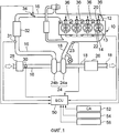
[0014] Фиг. 1 является концептуальной схемой, которая выражает структуру системы первого варианта осуществления настоящего изобретения.[0014] FIG. 1 is a conceptual diagram that expresses a system structure of a first embodiment of the present invention.
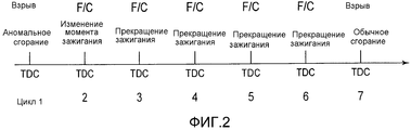
Фиг. 2 является временной диаграммой, которая показывает пример отличительного управления в первом варианте осуществления настоящего изобретения.FIG. 2 is a timing chart that shows an example of differential control in a first embodiment of the present invention.
Фиг. 3 является схемой, которая показывает изменение давления наддува, когда выполняется прекращение подачи топлива.FIG. 3 is a diagram that shows a change in boost pressure when a fuel cut is performed.
Фиг. 4 является блок-схемой последовательности операций процедуры управления, которую ECU 50 выполняет в первом варианте осуществления настоящего изобретения.FIG. 4 is a flowchart of a control procedure that the ECU 50 performs in the first embodiment of the present invention.
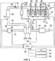
Фиг. 5 является концептуальной схемой, которая выражает структуру системы второго варианта осуществления настоящего изобретения.FIG. 5 is a conceptual diagram that expresses a system structure of a second embodiment of the present invention.
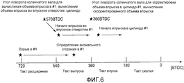
Фиг. 6 является временной диаграммой, которая показывает пример отличительного управления во втором варианте осуществления настоящего изобретения.FIG. 6 is a timing chart that shows an example of differential control in a second embodiment of the present invention.
Фиг. 7 является блок-схемой последовательности операций процедуры управления, которую ECU 50 выполняет во втором варианте осуществления настоящего изобретения.FIG. 7 is a flowchart of a control procedure that the ECU 50 performs in a second embodiment of the present invention.
Фиг. 8 является схемой, которая показывает пример, в котором цилиндр, формирующий аномальное сгорание, обнаруживается на основе 50% точки MFB (сжигаемая массовая доля).FIG. 8 is a diagram that shows an example in which an abnormal combustion cylinder is detected based on a 50% point of the MFB (mass fraction burned).
Фиг. 9 является схемой, которая показывает пример, в котором цилиндр, формирующий аномальное сгорание, обнаруживается на основе 50% точки MFB (сжигаемая массовая доля).FIG. 9 is a diagram that shows an example in which an abnormal combustion cylinder is detected based on a 50% point of the MFB (mass fraction burned).
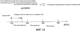
Фиг. 10 является схемой, которая показывает пример, в котором цилиндр, формирующий аномальное сгорание, обнаруживается на основе пикового напряжения в цилиндре.FIG. 10 is a diagram that shows an example in which an abnormal combustion cylinder is detected based on peak voltage in the cylinder.
ОПТИМАЛЬНЫЕ РЕЖИМЫ ОСУЩЕСТВЛЕНИЯ ИЗОБРЕТЕНИЯOPTIMUM MODES FOR CARRYING OUT THE INVENTION
[0015] Далее в данном документе, варианты осуществления настоящего изобретения будут описаны в деталях со ссылками на чертежи. Одинаковым элементам, общим на соответствующих чертежах, придаются одинаковые номера ссылок, и дублирующие описания опускаются.[0015] Hereinafter, embodiments of the present invention will be described in detail with reference to the drawings. Identical elements common to the corresponding drawings are given the same reference numbers, and duplicate descriptions are omitted.
[0016] ПЕРВЫЙ ВАРИАНТ ОСУЩЕСТВЛЕНИЯ[0016] FIRST EMBODIMENT
[СТРУКТУРА СИСТЕМЫ ПЕРВОГО ВАРИАНТА ОСУЩЕСТВЛЕНИЯ][SYSTEM STRUCTURE OF THE FIRST EMBODIMENT]
Фиг. 1 является концептуальной схемой, которая выражает структуру системы первого варианта осуществления настоящего изобретения. Система, показанная на фиг. 1, включает в себя двигатель 10 внутреннего сгорания (далее в данном документе просто называемый также двигателем), в котором рабочий объем цилиндра сокращен благодаря наддуву. Двигатель 10 внутреннего сгорания устанавливается в транспортном средстве или т.п. и используется в качестве источника его мощности. Хотя двигатель 10 внутреннего сгорания, показанный на фиг. 1, является двигателем рядного четырехцилиндрового типа, в настоящем изобретении, число цилиндров и размещение цилиндров не ограничивается этим. С целью удобства, в последующем описании цилиндры с первого по четвертый представляются как #1-#4, соответственно.FIG. 1 is a conceptual diagram that expresses a system structure of a first embodiment of the present invention. The system shown in FIG. 1 includes an internal combustion engine 10 (hereinafter, also simply referred to as an engine), in which the cylinder displacement is reduced due to boost. The
[0017] Каждый из цилиндров двигателя 10 внутреннего сгорания включает в себя форсунку 12 цилиндра, которая непосредственно впрыскивает топливо (например, бензин, этиловый спирт) в цилиндр (камеру сгорания), свечу 13 зажигания, которая зажигает газовую смесь, и датчик 14 давления в цилиндре, который выводит сигнал в соответствии с давлением в цилиндре.[0017] Each of the cylinders of the
[0018] С каждым из цилиндров двигателя 10 внутреннего сгорания соединяются впускной канал 16 и выпускной канал 18. На расположенном ниже по потоку конце впускного канала 16 размещается впускной клапан 20 для открытия/закрытия между внутренним пространством цилиндра (камерой сгорания) и впускным каналом 16. На расположенном выше по потоку конце выпускного канала 18 размещается выпускной клапан 22 для открытия/закрытия между внутренним пространством цилиндра (камеры сгорания) и выпускным каналом 18. Поблизости от части слияния выпускных каналов 18 размещается датчик 23 соотношения воздух-топливо для вывода сигнала в соответствии с соотношением воздух-топливо выхлопа.[0018] An
[0019] Отработавший газ, выпускаемый из каждого из цилиндров двигателя 10 внутреннего сгорания, протекает в выпускном канале 18. Двигатель 10 внутреннего сгорания включает в себя турбонагнетатель 24, который осуществляет наддув с помощью энергии отработавшего газа. Турбонагнетатель 24 включает в себя турбину 24a, которая вращается с помощью энергии отработавшего газа, и компрессор 24b, который вращается, будучи приводимым в действие турбиной 24a. Турбина 24a размещается в выпускном канале 18 ниже по потоку от датчика 23 соотношения воздух-топливо. Компрессор 24b размещается в середине впускного канала 16.[0019] The exhaust gas discharged from each of the cylinders of the
[0020] В выпускном канале 18 ниже по потоку от турбины 24a размещается каталитический нейтрализатор 26 для очистки вредных компонентов в отработавшем газе. В качестве каталитического нейтрализатора 26 используется, например, тройной катализатор.[0020] A
[0021] Поблизости от входного отверстия впускного канала размещается воздушный фильтр 28. Дополнительно, поблизости и ниже по потоку от воздушного фильтра 28 размещается расходомер 30 воздуха, который выводит сигнал в соответствии с расходом воздуха, всасываемого во впускной канал 16. Ниже по потоку от расходомера 30 воздуха размещается компрессор 24b. Ниже по потоку от компрессора 24b размещается датчик 31 давления наддува, который выводит сигнал в соответствии с давлением наддува. Ниже по потоку от датчика 31 давления наддува размещается промежуточный охладитель 32. Ниже по потоку от промежуточного охладителя 32 размещается дроссельная заслонка 34 с электронным типом управления. Ниже по потоку от дроссельной заслонки 34 размещается впускное отверстие 36 каждого из цилиндров.[0021] An
[0022] Свежий воздух, всасываемый через воздушный фильтр 28, сжимается компрессором 24b турбонагнетателя 24 и после этого охлаждается промежуточным охладителем 32. Охлажденный свежий воздух проходит через дроссельную заслонку 34, распределяется в каждый из цилиндров и протекает в них.[0022] Fresh air drawn in through the
[0023] Система настоящего варианта осуществления дополнительно включает в себя электронный блок управления (ECU) 50. ECU 50 сформирован из процессора, который включает в себя схему памяти, содержащую ROM, RAM и т.п., например. На входной стороне ECU 50 подключены отличные от датчика 14 давления в цилиндре, датчика 23 соотношения воздух-топливо, расходомера 30 воздуха и датчика 31 давления наддува, которые были описаны выше, различные датчики для обнаружения рабочего состояния двигателя 10 внутреннего сгорания, такие как датчик 52 угла поворота коленчатого вала для обнаружения угла поворота коленчатого вала и скорости изменения угла поворота коленчатого вала, датчик 54 детонации для обнаружения силы детонации, датчик 56 температуры охлаждающей жидкости для обнаружения температуры охлаждающей жидкости, которая охлаждает двигатель 10 внутреннего сгорания, и т.п. На выходной стороне ECU 50 подключены различные актуаторы для управления рабочим состоянием двигателя 10 внутреннего сгорания, такие как форсунка 12 цилиндра, свеча 13 зажигания, дроссельная заслонка 34 и т.п., которые были описаны выше.[0023] The system of the present embodiment further includes an electronic control unit (ECU) 50. The
[0024] ECU 50 имеет функцию запоминания различных данных, которые изменяются в зависимости от угла поворота коленчатого вала, как временных рядов данных вместе с соответствующим углом поворота коленчатого вала. Эти временные ряды данных включают в себя различные выходные данные датчиков, различные показатели, параметры и т.п., которые вычисляются на основе соответствующих выходных данных.[0024] The
[0025] ECU 50 приводит в действие различные актуаторы в соответствии с предварительно определенной процедурой на основе различных выходных данных датчиков и управляет рабочим состоянием двигателя 10 внутреннего сгорания. Например, угол поворота коленчатого вала и скорость вращения двигателя вычисляются на основе выходных данных датчика 52 угла поворота коленчатого вала, а объем всасываемого воздуха вычисляется на основе выходных данных расходомера 30 воздуха. Дополнительно, нагрузка двигателя (коэффициент нагрузки) вычисляется на основе объема всасываемого воздуха, скорости вращения двигателя и т.п. Объем впрыска топлива вычисляется на основе объема всасываемого воздуха, нагрузки и т.п. В качестве базового значения объема впрыска топлива устанавливается базовый объем впрыска топлива (базовый объем подачи топлива), который задает, например, соотношение воздух-топливо на выпуске равным теоретическому соотношению воздух-топливо (стехиометрическое соотношение) (функция задания объема подачи топлива). Момент зажигания топлива и момент зажигания для электрического соединения со свечой 13 зажигания определяются на основе угла поворота коленчатого вала. В качестве базового значения момента зажигания задается базовый момент зажигания, соответствующий рабочей области, которая определяется скоростью вращения двигателя и нагрузкой (функция задания базового момента зажигания). Затем, когда эти моменты наступают, форсунка 12 цилиндра и свеча 13 зажигания возбуждаются. Таким образом, воздушная смесь может сжигаться в цилиндре, и двигатель 10 внутреннего сгорания может приводиться в действие таким образом.[0025] The
[0026] [ОТЛИЧИТЕЛЬНОЕ УПРАВЛЕНИЕ В ПЕРВОМ ВАРИАНТЕ ОСУЩЕСТВЛЕНИЯ][0026] [DISTINCTIVE MANAGEMENT IN THE FIRST OPTION OF IMPLEMENTATION]
В двигателе с наддувом, аналогичном системе настоящего варианта осуществления, в области работы с наддувом (например, области высокой нагрузки при низкой скорости вращения) имеет тенденцию возникать аномальное сгорание, такое как неожиданное преждевременное зажигание или т.п. В качестве фактора возникновения аномального сгорания могут быть упомянуты масляный туман и отложения, откладываемые в камере сгорания и на поршне. Постоянное формирование аномального сгорания становится фактором, который увеличивает вибрацию или шум и механическое напряжение двигателя.In a supercharged engine similar to the system of the present embodiment, abnormal combustion, such as sudden premature ignition or the like, tends to occur in the supercharged area (for example, the high load region at low rotational speed). As a factor in the occurrence of abnormal combustion, oil mist and deposits deposited in the combustion chamber and on the piston may be mentioned. The constant formation of abnormal combustion becomes a factor that increases vibration or noise and mechanical stress of the engine.
[0027] Для того чтобы предотвращать постоянное возникновение аномального сгорания, рассматриваются меры для обогащения соотношения воздух-топливо (в дальнейшем называемого просто как A/F в некоторых случаях) за счет увеличения объема топлива. Вследствие увеличения в объеме топлива температура в конце такта сжатия снижается за счет скрытой теплоты испарения топлива. Дополнительно, также рассматривается выполнение прекращения подачи топлива (в дальнейшем просто называемое F/C). Когда выполняется прекращение подачи топлива, температура в цилиндре снижается за счет прекращения самого сгорания. Дополнительно, выполняя эти управления в течение предварительно определенных циклов или предварительно определенного периода, отложения, отслаиваемые или перемещаемые за счет ударной волны преждевременного зажигания, выпускаются.[0027] In order to prevent the constant occurrence of abnormal combustion, measures are considered to enrich the air-fuel ratio (hereinafter simply referred to as A / F in some cases) by increasing the volume of fuel. Due to the increase in fuel volume, the temperature at the end of the compression stroke decreases due to the latent heat of vaporization of the fuel. Additionally, the execution of a fuel cut-off (hereinafter simply referred to as F / C) is also contemplated. When the fuel supply is cut off, the temperature in the cylinder decreases due to the cessation of combustion itself. Additionally, performing these controls over predefined cycles or a predetermined period, deposits peeled off or moved by the shock wave of premature ignition are released.
[0028] В системе настоящего варианта осуществления, когда постоянное формирование аномального сгорания не может быть прекращено даже посредством установления обогащенного состояния A/F, выполняется прекращение подачи топлива. Когда выполняется прекращение подачи топлива, топливо не впрыскивается. Следовательно, топливо в цилиндре формируется только из влажной части топлива в цилиндре и влажной части топлива во впускном отверстии. В результате, формируется состояние обедненного A/F. В состоянии обедненного A/F, поскольку концентрация топлива разреженная, требуемое напряжение зажигания системы зажигания растет. Следовательно, требуемое напряжение зажигания может превышать выдерживаемое напряжение всей системы зажигания (свечи 13 зажигания, трубки свечи, соответствующих соединительных частей и т.п.). С учетом расхода, расширения искрового зазора между центральным электродом и заземляющим электродом свечи 13 зажигания и флуктуации продуктов сгорания, выдерживаемое напряжение всей системы зажигания превышается с высокой вероятностью. В частности, ситуация становится тяжелой во время вращения с низкой скоростью, когда давление наддува является высоким, а температура в цилиндре является низкой.[0028] In the system of the present embodiment, when the continuous formation of abnormal combustion cannot be stopped even by setting the A / F rich state, the fuel supply is shut off. When a fuel cut is performed, fuel is not injected. Therefore, the fuel in the cylinder is formed only from the wet part of the fuel in the cylinder and the wet part of the fuel in the inlet. As a result, a depleted A / F state is formed. In the lean A / F state, as the fuel concentration is sparse, the required ignition voltage of the ignition system rises. Therefore, the required ignition voltage may exceed the withstand voltage of the entire ignition system (spark plugs 13, spark plug tubes, corresponding connecting parts, etc.). Given the flow rate, the expansion of the spark gap between the central electrode and the ground electrode of the
[0029] Когда выдерживаемое напряжение превышается, возникает высоковольтная утечка в части системы зажигания (создается точечное отверстие). Следовательно, недостаток заключается в том, что при возврате из состояния прекращения подачи топлива в нормальное состояние могут возникать пропуски зажигания. Дополнительно, недостаток заключается в том, что вследствие пропуска зажигания неиспользуемое топливо и поток воздуха попадают в каталитический нейтрализатор 26, каталитический нейтрализатор плавится при высокой температуре вследствие окислительной реакции.[0029] When the withstand voltage is exceeded, a high voltage leakage occurs in a part of the ignition system (a point hole is created). Therefore, the disadvantage is that when the fuel returns to its normal state, misfire may occur. Additionally, the disadvantage is that due to misfire, unused fuel and air flow enter the
[0030] Дополнительно, в целом, затруднительно выполнять зажигание в двигателе с наддувом, и он не является хорошим в отношении горючести. Затруднение зажигания в двигателе с наддувом обусловлено тем, что давление сжатия выше, чем у NA-двигателя, и при этом требуемое напряжение зажигания выше, чем у NA-двигателя. Хотя с точки зрения горючести желателен долговременный выпуск. Однако многократность энергии зажигания необходима по сравнению с NA-двигателем. Следовательно, желательно улучшение в потреблении топлива вследствие уменьшения в потребляемой мощности. С таких предпосылок, в настоящей системе преследуется цель улучшения в расходе топлива благодаря уменьшению в потребляемой мощности вследствие прекращения зажигания. В двигателе с наддувом, аналогичном настоящей системе, преимущество вследствие улучшения расхода топлива за счет прекращения зажигания больше, чем в NA-двигателе.[0030] Additionally, it is generally difficult to perform ignition in a supercharged engine, and it is not good in terms of combustibility. The ignition difficulty in a supercharged engine is due to the fact that the compression pressure is higher than that of a NA engine, and the required ignition voltage is higher than that of a NA engine. Although in terms of combustibility, long-term release is desirable. However, a multiplicity of ignition energy is necessary compared to a NA engine. Therefore, an improvement in fuel consumption due to a decrease in power consumption is desired. With such assumptions, the present system aims to improve fuel consumption by reducing the power consumption due to the cessation of ignition. In a supercharged engine similar to the present system, the advantage due to improved fuel consumption due to the cessation of ignition is greater than in a NA engine.
[0031] Здесь, контроллер двигателя внутреннего сгорания с нагнетателем настоящего варианта осуществления выполняет прекращение подачи топлива для цилиндра, формирующего аномальное сгорание, в котором аномальное сгорание происходит в области работы с наддувом. Здесь, в течение нескольких циклов после начала прекращения подачи топлива, момент зажигания изменяется так, что ширина угла поворота коленчатого вала между верхней мертвой точкой такта сжатия и базовым моментом зажигания расширяется. Дополнительно, после прохождения нескольких циклов, описанных выше, прекращение зажигания выполняется во время продолжающегося прекращения подачи топлива.[0031] Here, the controller of the internal combustion engine with the supercharger of the present embodiment performs the fuel cutoff for the cylinder generating abnormal combustion, in which abnormal combustion occurs in the supercharged operation area. Here, for several cycles after the start of the cessation of fuel supply, the ignition moment is changed so that the width of the angle of rotation of the crankshaft between the top dead center of the compression stroke and the base moment of ignition expands. Additionally, after going through the several cycles described above, the ignition stop is performed during the ongoing shutdown of the fuel supply.
[0032] Желательно, перед прекращением подачи топлива, чтобы базовый объем подачи топлива, описанный выше, для цилиндра, формирующего аномальное сгорание, описанного выше, увеличивался и корректировался в течение предварительно определенных циклов. Когда даже после прохождения предварительно определенных циклов, описанных выше, аномальное сгорание все еще происходит, выполняется прекращение подачи топлива. Когда аномальное сгорание может предотвращаться посредством обогащения A/F, нет необходимости выполнения прекращения подачи топлива. Следовательно, без опасения высоковольтной утечки, аномальное сгорание может быть пресечено.[0032] Preferably, before the fuel supply is shut off, the base fuel supply volume described above for the cylinder forming the abnormal combustion described above is increased and adjusted during predetermined cycles. When even after passing through the predetermined cycles described above, abnormal combustion still occurs, the fuel supply is cut off. When abnormal combustion can be prevented by A / F enrichment, there is no need to complete a fuel cut. Therefore, without fear of high voltage leakage, abnormal combustion can be suppressed.
[0033] Более предпочтительно, управление для изменения момента зажигания, описанное выше, задается таким образом, что момент зажигания запаздывает. Поскольку в предыдущем цикле, в котором выполнено прекращение подачи топлива, поскольку базовый объем подачи топлива увеличивается и корректируется, объем влажного топлива, такой как влажная часть топлива в цилиндре и влажная часть топлива во впускном отверстии, вследствие обратной вспышки является большим. Для того чтобы пресекать возникновение зажигания на стороне опережения, когда большой объем влажной части топлива поступает в цилиндр, ширина угла поворота коленчатого вала расширяется в сторону угла запаздывания. Посредством большого запаздывания момента зажигания большой объем остающегося топлива сжигается, и тем самым уменьшается объем неиспользованного газа.[0033] More preferably, the control for changing the ignition timing described above is set so that the ignition timing is delayed. Since in the previous cycle in which the fuel supply was shut off, since the base fuel supply volume is increased and corrected, the amount of wet fuel, such as the wet part of the fuel in the cylinder and the wet part of the fuel in the inlet, is large due to the flashback. In order to prevent the occurrence of ignition on the leading side, when a large volume of the wet part of the fuel enters the cylinder, the width of the angle of rotation of the crankshaft expands towards the angle of delay. Due to the large delay of the ignition moment, a large amount of the remaining fuel is burned, and thereby the volume of unused gas is reduced.
[0034] Основной принцип отличительного управления в системе настоящего варианта осуществления будет описан более конкретно. Фиг. 2 является временной диаграммой, которая показывает пример отличительного управления в системе настоящего варианта осуществления. В примере, показанном на фиг. 2, сначала, в цикле 1, ECU 50 обнаруживает цилиндр, формирующий аномальное сгорание, в котором аномальное сгорание происходит поблизости от верхней мертвой точки (TDC) такта сжатия. Далее, в цикле 2, ECU 50 выполняет прекращение подачи топлива для цилиндра, формирующего аномальное сгорание, и в то же время изменяет момент зажигания, как описано выше. После этого, в цикле 3, ECU 50 выполняет прекращение зажигания, в то же время продолжая прекращение подачи топлива. В течение циклов 4-6 прекращение подачи топлива и прекращение зажигания продолжаются. В цикле 8, удовлетворяется условие возобновления подачи топлива, и посредством восстановления нормального состояния после прекращения подачи топлива выполняется нормальное сгорание.[0034] The basic principle of distinctive control in the system of the present embodiment will be described more specifically. FIG. 2 is a timing chart that shows an example of differential control in the system of the present embodiment. In the example shown in FIG. 2, first, in
[0035] Фиг. 3 является схемой, которая показывает изменение давления наддува, когда выполняется прекращение подачи топлива. Как показано на фиг. 3, когда рабочая область находится в области наддува, даже если прекращение подачи топлива выполняется в момент t1 времени, до момента t2 времени, состояние, когда давление наддува выше порогового значения, продолжается. Пороговое значение соответствует выдерживаемому напряжению системы зажигания. Состояние, в котором давление наддува выше порогового значения, может продолжаться в течение нескольких циклов. Поскольку требуемое напряжение зажигания является высоким в течение этих нескольких циклов, в системе настоящего варианта осуществления, момент зажигания изменяется, как описано выше. Таким образом, может пресекаться возникновение высоковольтной утечки.[0035] FIG. 3 is a diagram that shows a change in boost pressure when a fuel cut is performed. As shown in FIG. 3, when the working area is in the boost region, even if the fuel cutoff is performed at time t1, until time t2, the state where the boost pressure is above the threshold value continues. The threshold value corresponds to the withstand voltage of the ignition system. A condition in which boost pressure is above a threshold value may continue for several cycles. Since the required ignition voltage is high during these several cycles, in the system of the present embodiment, the ignition timing is changed as described above. Thus, the occurrence of high voltage leakage can be suppressed.
[0036] Фиг. 4 является блок-схемой последовательности операций процедуры управления, которую ECU 50 выполняет, чтобы реализовывать работу, описанную выше. В процедуре, показанной на фиг. 4, сначала, ECU 50 определяет, возникло ли аномальное сгорание для каждого из цилиндров (этап S100). Например, ECU 50 определяет, произошло ли аномальное сгорание, такое как преждевременное зажигание или т.п., на основе соотношения между углом поворота коленчатого вала, при котором датчик 14 давления в цилиндре или датчик 54 детонации вывел пиковое значение, и моментом зажигания. Когда пиковое значение было выведено при угле поворота коленчатого вала, который опережает по фазе на предварительно определенное значение или больше угол во время нормального сжигания, определяется, что произошло аномальное сгорание. Дополнительно, когда 50% точка MFB (сожженная массовая доля) находится раньше на предварительно определенное значение или более, чем точка во время нормального сгорания, может также быть определено, что произошло аномальное сгорание. Когда аномальное сгорание не происходит, выполняется обычное управление (этап S190), обработка настоящей процедуры завершается.[0036] FIG. 4 is a flowchart of a control procedure that the
[0037] Когда было определено, что аномальное сгорание произошло, на этапе S100, ECU 50 выполняет первое управление предотвращения постоянного формирования для подавления постоянного формирования аномального сгорания (этап S110). В первом управлении для предотвращения постоянного формирования базовый объем впрыска топлива, который подается в цилиндр, формирующий аномальное сгорание, увеличивается и корректируется. Состояние обогащенного A/F может быть достигнуто посредством увеличения и корректировки. Например, соотношение воздух-топливо изменяется с 14,6 (стехиометрического) до 12. Когда было определено, что аномальное сгорание произошло во множестве цилиндров в течение одного цикла, базовый объем впрыска топлива увеличивается и корректируется во всех цилиндрах.[0037] When it was determined that abnormal combustion occurred, in step S100, the
[0038] ECU 50 определяет, прошли ли предварительно определенные циклы или предварительно определенное время после того, как было выполнено первое управление для предотвращения постоянного формирования (этап S120). Когда предварительно определенные циклы или предварительно определенное время не прошли, обработка этапа S110 возобновляется.[0038] The
[0039] С другой стороны, когда предварительно определенные циклы или предварительно определенное время прошли, ECU 50 определяет, продолжается ли аномальное сгорание в цилиндре, формирующем аномальное сгорание, который был обнаружен на этапе S100, т.е. происходит ли постоянно аномальное сгорание (этап S130). Когда аномальное сгорание не формируется, выполняется обычное управление (этап S190), обработка настоящей процедуры завершается.[0039] On the other hand, when the predetermined cycles or the predetermined time has passed, the
[0040] Когда определяется, что аномальное сгорание происходит постоянно, на этапе S130, ECU 50 определяет, что постоянное формирование аномального сгорания могло быть не пресечено посредством первого управления для пресечения постоянного формирования. В этом отношении, ECU 50 выполняет второе управление для предотвращения постоянного формирования (этап S140). Во втором управлении для предотвращения постоянного формирования выполняется прекращение подачи топлива (F/C), которое прекращает подачу топлива в цилиндр, формирующий аномальное сгорание, описанный выше. Когда было определено, что аномальное сгорание произошло во множестве цилиндров в течение одного цикла, прекращение подачи топлива выполняется во всех цилиндрах.[0040] When it is determined that abnormal combustion occurs continuously, in step S130, the
[0041] ECU 50 определяет, находится ли он в пределах нескольких циклов после начала прекращения подачи топлива (этап S150). В качестве нескольких циклов, например, время от начала выполнения прекращения подачи топлива до времени, когда давление наддува падает ниже порогового значения (фиг. 3), может быть задано заранее на основе эксперимента или моделирования. Дополнительно, определяя, упало ли давление наддува ниже порогового значения для каждого цикла, когда давление наддува упало ниже порогового значения, условие определения на этапе S150 может считаться удовлетворенным.[0041] The
[0042] В случае нахождения в пределах нескольких циклов, описанном выше, ECU 50 изменяет момент зажигания цилиндра, формирующего аномальное сгорание, в котором выполняется прекращение подачи топлива (этап S160). В частности, ECU 50 устанавливает опережающий или запаздывающий момент зажигания так, что ширина угла поворота коленчатого вала от верхней мертвой точки такта сжатия до базового момента зажигания расширяется. Поскольку давление в цилиндре определяется позицией коленчатого вала, изменение базового момента зажигания выполняется не посредством относительной корректировки от базового момента зажигания, а посредством замены карты, которая определяет базовый момент зажигания. ECU 50 имеет скорректированную карту, в которой определены базовые моменты зажигания после корректировки, которые соответствуют скорости вращения и нагрузке двигателя, и заменяют карту на этапе S160. Дополнительно, предпочтительно, параметр температуры охлаждающей жидкости добавляется в скорректированную карту. Поскольку, чем ниже температура в цилиндре, тем выше становится требуемое напряжение зажигания, с учетом безопасности, чем ниже температура охлаждающей жидкости на этапе прогрева (в холодное время), тем большим устанавливается угол опережения или запаздывания.[0042] If it is within the several cycles described above, the
[0043] В последующем описании верхняя мертвая точка такта сжатия выражается как 0°, позиция опережения на 20° выражается как 20BTDC, а позиция запаздывания на 20° выражается как 20ATDC. Заменяя карту, например, в то время как базовый момент зажигания, соответствующий рабочей области в исходной карте, задан в 5ATDC, в скорректированной карте могут быть заданы 20ATDC или 20BTDC. Вычисление базового момента зажигания выполняется, например, при 240BTDC, а повторное вычисление вследствие скорректированной карты выполняется, например, при 90BTDC. Эти вычисления выполняются посредством процедуры, отдельной от впрыска топлива.[0043] In the following description, the top dead center of the compression measure is expressed as 0 °, the lead position of 20 ° is expressed as 20BTDC, and the delay position of 20 ° is expressed as 20ATDC. Replacing the card, for example, while the ignition base moment corresponding to the working area in the original card is set to 5ATDC, 20ATDC or 20BTDC can be set in the adjusted card. The calculation of the ignition timing is performed, for example, at 240BTDC, and the recalculation due to the adjusted map is performed, for example, at 90BTDC. These calculations are performed through a procedure separate from the fuel injection.
[0044] Пока предварительно определенные циклы или предварительно определенное время не пройдут после начала прекращения подачи топлива после обработки этапа S160, обработка S140 возобновляется (этап S180). После чего, когда несколько циклов прошли от начала прекращения подачи топлива, и условие определения этапа S150 удовлетворяется, ECU 50 прекращает зажигание цилиндра во время прекращения подачи топлива (этап S170). После начала прекращения подачи топлива, когда предварительно определенные циклы или предварительно определенное время прошли (этап S180), обработка возвращается к обычному управлению от прекращения подачи топлива (этап S180), и текущая процедура завершается.[0044] Until the predetermined cycles or the predetermined time have elapsed after the start of the fuel cut off after the processing of step S160, the processing S140 is resumed (step S180). Then, when several cycles have passed from the start of the fuel cutoff, and the determination condition of step S150 is satisfied, the
[0045] Как описано выше, согласно процедуре, показанной на фиг. 4, прежде всего, выполняется управление для пресечения аномального сгорания вследствие обогащения A/F. В случае, когда аномальное сгорание пресекается вследствие обогащения A/F, нет необходимости в прекращении подачи топлива. Следовательно, без опасения высоковольтной утечки, аномальное сгорание может быть пресечено.[0045] As described above, according to the procedure shown in FIG. 4, control is first performed to suppress abnormal combustion due to A / F enrichment. In the event that abnormal combustion is suppressed due to A / F enrichment, there is no need to shut off the fuel supply. Therefore, without fear of high voltage leakage, abnormal combustion can be suppressed.
[0046] Дополнительно, изменяя момент зажигания после начала прекращения подачи топлива, зажигание может выполняться в состоянии, когда давление в цилиндре является низким. Поскольку давление в цилиндре является низким, может предотвращаться чрезмерный рост требуемого напряжения зажигания. В частности, это эффективно, поскольку двигатель наддува имеет более высокое давление в цилиндре, чем в NA-двигателе. Дополнительно, неиспользованное топливо может сжигаться посредством зажигания. В частности, это эффективно на этапе прогрева (в холодное время), поскольку объем прилипающего топлива (объем влажного топлива) является большим.[0046] Further, by varying the ignition timing after the start of the fuel cutoff, ignition can be performed in a state where the pressure in the cylinder is low. Since the pressure in the cylinder is low, an excessive increase in the required ignition voltage can be prevented. In particular, this is effective because the boost engine has a higher cylinder pressure than the NA engine. Additionally, unused fuel can be burned by ignition. In particular, it is effective at the warm-up stage (in cold weather), since the amount of adhering fuel (the volume of wet fuel) is large.
[0047] Дополнительно, во время прекращения подачи топлива может выполняться прекращение зажигания. Следовательно, может достигаться улучшение в расходе топлива вследствие уменьшения потребляемой мощности. В частности, прекращение зажигания является эффективным в улучшении расхода топлива, поскольку двигатель с наддувом имеет высокую энергию зажигания по сравнению с NA-двигателем.[0047] Additionally, during the fuel cutoff, the ignition cutoff can be performed. Therefore, an improvement in fuel consumption due to a reduction in power consumption can be achieved. In particular, ignition cessation is effective in improving fuel consumption, since a supercharged engine has a high ignition energy compared to a NA engine.
[0048] Таким образом, согласно системе настоящего варианта осуществления, когда прекращение подачи топлива выполняется для пресечения возникновения постоянного формирования аномального сгорания в области наддува в двигателе внутреннего сгорания с нагнетателем, пресечение чрезмерного роста требуемого напряжения зажигания и улучшение в расходе топлива могут быть объединены.[0048] Thus, according to the system of the present embodiment, when the fuel cut-off is performed to suppress the occurrence of constant formation of abnormal combustion in the boost region in the internal combustion engine with the supercharger, suppressing an excessive increase in the required ignition voltage and an improvement in fuel consumption can be combined.
[0049] Здесь, в системе первого варианта осуществления, описанного выше, для каждого цилиндра предусмотрена одна форсунка 12 цилиндра. Однако размещение и число форсунок не ограничивается этим. Например, форсунка цилиндра и форсунка распределительного впрыска могут быть предусмотрены для каждого из цилиндров. Дополнительно, может быть предусмотрена только форсунка распределительного впрыска.[0049] Here, in the system of the first embodiment described above, one
[0050] Дополнительно, в системе первого варианта осуществления, описанного выше, ECU 50 запоминает скорректированную карту, которая определяет соотношение между скоростью вращения двигателя, нагрузкой и температурой охлаждающей жидкости и базовыми моментами зажигания. Однако вместо скорректированной карты могут быть использованы фиксированные значения (например, 20ATDC).[0050] Additionally, in the system of the first embodiment described above, the
[0051] В первом варианте осуществления, описанном выше, форсунка 12 цилиндра, свеча 13 зажигания, функция задания базового момента зажигания и функция задания объема подаваемого топлива соответствуют "средству подачи топлива" в первом изобретении, "свече зажигания" в первом изобретении, "средству задания момента зажигания" в первом изобретении и "средству задания объема подаваемого топлива" во втором изобретении соответственно.[0051] In the first embodiment described above, the
[0052] Дополнительно, здесь, когда ECU 50 выполняет обработки этапов S100 и S130, описанных выше, обработку этапа S110, описанного выше, обработку этапа S140, описанного выше, и обработки этапов S150-S170, описанных выше, "средство обнаружения цилиндра, формирующего аномальное сгорание" в первом изобретении, "средство увеличения и корректировки объема подачи топлива" во втором изобретении, "средство выполнения прекращения подачи топлива" в первом изобретении и "средство управления зажиганием во время выполнения прекращения подачи топлива" в первом изобретении могут быть, соответственно, реализованы.[0052] Further, here, when the
[0053] ВТОРОЙ ВАРИАНТ ОСУЩЕСТВЛЕНИЯ[0053] SECOND EMBODIMENT
[СТРУКТУРА СИСТЕМЫ ВТОРОГО ВАРИАНТА ОСУЩЕСТВЛЕНИЯ][SYSTEM STRUCTURE OF THE SECOND EMBODIMENT]
Далее, второй вариант осуществления настоящего изобретения будет описан со ссылкой на фиг. 5-10. Система настоящего варианта осуществления может быть реализована посредством инструктирования ECU 50 выполнять процедуру на фиг. 7, описанную ниже, в структуре, показанной на фиг. 5.Next, a second embodiment of the present invention will be described with reference to FIG. 5-10. The system of the present embodiment may be implemented by instructing the
[0054] Фиг. 5 является концептуальной схемой, которая выражает структуру системы второго варианта осуществления настоящего изобретения. Система настоящего варианта осуществления включает в себя две форсунки из форсунки 11 распределительного впрыска и форсунки 12 цилиндра для каждого цилиндра. Форсунка 11 распределительного впрыска размещается во впускном отверстии 36 и выполняет впрыск топлива во впускное отверстие по направлению к внутреннему пространству цилиндра (камере сгорания). Форсунка 12 цилиндра впрыскивает топливо непосредственно в цилиндр (камеру сгорания). Другие основные структуры являются такими же, что и на фиг. 1. В дальнейшем, на фиг. 5, структурам, аналогичным фиг. 1, присвоены аналогичные ссылочные номера, и их описания опускаются или упрощаются.[0054] FIG. 5 is a conceptual diagram that expresses a system structure of a second embodiment of the present invention. The system of the present embodiment includes two nozzles from a
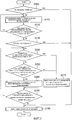
[0055] ECU 50 настоящего варианта осуществления задает, в зависимости от рабочего состояния, например, базовый объем впрыска топлива (общую сумму объемов впрыскиваемого топлива двух впрысков), что делает соотношение воздух-топливо выхлопа теоретическим соотношением воздух-топливо (функция задания объема подачи топлива). Дополнительно, функция задания объема подачи топлива вычисляет объем впрыска топлива форсунки 12 цилиндра и объем впрыска топлива форсунки 11 распределительного впрыска на основе базового объема впрыска топлива. Эти объемы впрыска топлива для следующего цикла вычисляются в такте расширения текущего цикла. После этого форсунка 11 распределительного впрыска начинает впрыск топлива в такте расширения, а форсунка 12 цилиндра начинает впрыск топлива в такте впуска.[0055] The
[0056] Теперь, что касается предварительно определенного цилиндра, после того как объем впрыска топлива форсунки 11 распределительного впрыска вычислен и форсунка распределительного впрыска начинает впрыск топлива для следующего цикла, существует случай, в котором предварительно определенный цилиндр, описанный выше, обнаруживается как цилиндр, формирующий аномальное сгорание, в текущем цикле. Это обусловлено тем, что, когда момент времени обнаружения аномального сгорания является запаздывающим, управление прекращением впрыска по отношению к форсунке 11 распределительного впрыска запаздывает, и существует случай, в котором этап не может быть перемещен к прекращению подачи топлива. В этом случае, прекращение подачи топлива не может выполняться в следующем цикле.[0056] Now, with regard to the predetermined cylinder, after the fuel injection volume of the
[0057] [ОТЛИЧИТЕЛЬНОЕ УПРАВЛЕНИЕ ВО ВТОРОМ ВАРИАНТЕ ОСУЩЕСТВЛЕНИЯ][0057] [DISTINCTIVE MANAGEMENT IN A SECOND EMBODIMENT]
Здесь, в системе настоящего варианта осуществления, в отношении предварительно определенного цилиндра, когда предварительно определенный цилиндр, описанный выше, обнаруживается как цилиндр, формирующий аномальное сгорание, в текущем цикле, после того как форсунка 11 распределительного впрыска начинает впрыск топлива для следующего цикла в такте выпуска, объем впрыска топлива следующего цикла, описанный выше, для форсунки 12 цилиндра увеличивается и корректируется. Затем прекращение подачи топлива выполняется с цикла после следующего цикла, описанного выше.Here, in the system of the present embodiment, with respect to the predetermined cylinder, when the predetermined cylinder described above is detected as an abnormal combustion cylinder in the current cycle after the
[0058] Основной принцип отличительного управления в системе настоящего варианта осуществления будет описан более конкретно. Фиг. 6 является временной диаграммой, которая показывает пример отличительного управления в системе настоящего варианта осуществления. В последующем описании верхняя мертвая точка такта сжатия выражается как 0°, а позиция, опережающая на 20°, выражается как 20ATDC.[0058] The basic principle of distinctive control in the system of the present embodiment will be described more specifically. FIG. 6 is a timing chart that shows an example of differential control in the system of the present embodiment. In the following description, the top dead center of the compression measure is expressed as 0 °, and a position ahead of 20 ° is expressed as 20ATDC.
[0059] В примере, показанном на фиг. 6, момент времени (угол поворота коленчатого вала для вычисления объема впрыска в #1), в который вычисляются объем впрыска топлива форсунки 11 распределительного впрыска и объем впрыска топлива форсунки 12 цилиндра для первого цилиндра (#1), является более ранним, чем момент определения аномального сгорания для #1. Следовательно, выполнение прекращения подачи топлива запаздывает, и впрыск топлива форсункой 11 распределительного впрыска для #1 начинается. В этом случае, ECU 50 увеличивает и корректирует объем впрыска топлива благодаря форсунке 12 цилиндра #1. Вследствие того что A/F в значительной степени обогащается посредством этого увеличения и корректировки, температура в конце сжатия понижается.[0059] In the example shown in FIG. 6, the point in time (crank angle to calculate the injection volume at # 1), at which the fuel injection volume of the
[0060] Фиг. 7 является блок-схемой последовательности операций процедуры управления, которую ECU 50 выполняет для реализации работы, описанной выше. Эта процедура является такой же, что и процедура, показанная на фиг. 4, за исключением того, что обработки с этапа S140 по этап S170 заменены обработками с этапа S240 по этап S270. В дальнейшем, на фиг. 7, те же этапы, что и показанные на фиг. 4, снабжены теми же ссылочными номерами, и их описания опускаются или упрощаются.[0060] FIG. 7 is a flowchart of a control procedure that the
[0061] На этапе S240 ECU 50 определяет, обнаруживается ли возникновение формирования аномального сгорания на этапе S130 в первый раз в текущей процедуре. Когда это первый раз, ECU 50 определяет, находится ли текущий угол поворота коленчатого вала на стороне угла запаздывания, чем угол поворота коленчатого вала для вычисления объема впрыска (этап S250). Другими словами, ECU 50 определяет, является ли угол поворота коленчатого вала для вычисления объема впрыска более ранним, чем угол поворота коленчатого вала, при котором обнаруживается цилиндр, формирующий аномальное сгорание. Когда это условие определения удовлетворяется, выполняется третье управление для предотвращения постоянного формирования (этап S260). Третье управление для предотвращения постоянного формирования увеличивает и корректирует объем впрыска топлива форсунки 12 цилиндра, заданный посредством функции задания объема подачи топлива. Таким образом, задается состояние обогащенного A/F (например, A/F=10) больше, чем при первом управлении для предотвращения постоянного формирования на этапе S110.[0061] In step S240, the
[0062] С другой стороны, на этапе S250, когда текущий угол поворота коленчатого вала находится на стороне угла опережения, чем угол поворота коленчатого вала для вычисления объема впрыска, при текущем угле поворота коленчатого вала, объем впрыска топлива следующего цикла форсунки 11 распределительного впрыска не вычислен. В этом случае, поскольку выполнение прекращения подачи топлива соответствует цели, выполняется второе управление для предотвращения постоянного формирования, описанное в первом варианте осуществления.[0062] On the other hand, in step S250, when the current angle of rotation of the crankshaft is on the side of the advance angle than the angle of rotation of the crankshaft to calculate the injection volume, at the current angle of rotation of the crankshaft, the fuel injection volume of the next cycle of the
[0063] Аналогично, также, когда условие определения не удовлетворяется на этапе S240, выполняется обработка этапа S250. Это обусловлено тем, что прошел один цикл, и прекращение подачи топлива соответствует цели.[0063] Similarly, also, when the determination condition is not satisfied in step S240, the processing of step S250 is performed. This is due to the fact that one cycle has passed and the cessation of fuel supply is consistent with the goal.
[0064] Как описано выше, согласно процедуре, показанной на фиг. 7, когда первое управление для предотвращения постоянного формирования (богатое A/F) не может мгновенно перейти ко второму управлению для предотвращения постоянного формирования (прекращение подачи топлива), объем впрыска топлива форсунки 12 цилиндра может быть увеличен и скорректирован. Т.е., объем впрыска топлива, который был увеличен и скорректирован в первом управлении для предотвращения постоянного формирования, может быть дополнительно увеличен и скорректирован. Следовательно, температура в конце такта сжатия может быть дополнительно понижена благодаря обогащению A/F, и, в результате, может быть пресечено возникновение аномального сгорания. Дополнительно, даже когда аномальное сгорание произошло, возникает эффект, что пиковое давление в цилиндре понижается и вибрация, шум и повреждение двигателя ослабевают. Дополнительно, в следующем цикле, посредством выполнения прекращения подачи топлива может более надежно пресекаться возникновение аномального сгорания.[0064] As described above, according to the procedure shown in FIG. 7, when the first control to prevent continuous formation (rich A / F) cannot instantly switch to the second control to prevent continuous formation (fuel cut), the fuel injection volume of the
[0065] [МОМЕНТ ВРЕМЕНИ, КОГДА ОБНАРУЖИВАЕТСЯ ЦИЛИНДР, ФОРМИРУЮЩИЙ АНОМАЛЬНОЕ СГОРАНИЕ][0065] [TIME WHEN A CYLINDER FORMING ANOMALOUS COMBUSTION IS DETECTED]
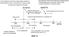
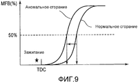
Момент времени, когда цилиндр, формирующий аномальное сгорание, описанный выше, обнаруживается, будет описан со ссылкой на фиг. 8-10. Фиг. 8 является схемой, которая показывает пример, в котором цилиндр, формирующий аномальное сгорание, обнаруживается на основе 50% точки MFB. Как показано на фиг. 9, цилиндр формирования аномального сгорания может быть обнаружен на основе различия между 50% точками MFB во время нормального сгорания и аномального сгорания. Для того чтобы вычислять 50% точку MFB (сгоревшая массовая доля), необходимо измерять давление в цилиндре до конца сгорания с помощью датчика 14 давления в цилиндре. В результате, как показано на фиг. 8, в некоторых случаях, момент времени вычисления 50% точки MFB становится более поздним, чем угол поворота коленчатого вала для вычисления объема впрыска и момент времени начала впрыска во впускное отверстие. Следовательно, отличительное управление настоящего варианта осуществления, описанного выше, является эффективным.The point in time when the cylinder forming the abnormal combustion described above is detected will be described with reference to FIG. 8-10. FIG. 8 is a diagram that shows an example in which an abnormal combustion cylinder is detected based on 50% of the MFB point. As shown in FIG. 9, an abnormal combustion formation cylinder can be detected based on the difference between 50% MFB points during normal combustion and abnormal combustion. In order to calculate the 50% point of the MFB (burnt mass fraction), it is necessary to measure the pressure in the cylinder to the end of combustion using the
[0066] Фиг. 10 является схемой, которая показывает пример, который обнаруживает цилиндр, формирующий аномальное сгорание, на основе пикового давления в цилиндре. Как показано на фиг. 10, согласно обнаружению благодаря моменту времени формирования пикового давления в цилиндре, вероятность того, что результат определения аномального сгорания соответствует цели угла поворота коленчатого вала для вычисления объема впрыска в цилиндр, является высокой. Однако, в случае топлива с низким RON (октановое число по исследовательскому методу), вероятность несоответствия цели становится выше, поскольку аномальное сгорание возникает на стороне угла запаздывания. Следовательно, отличительное управление настоящего варианта осуществления, описанного выше, является эффективным.[0066] FIG. 10 is a diagram that shows an example that detects an abnormal combustion cylinder based on peak pressure in the cylinder. As shown in FIG. 10, according to the detection due to the moment of formation of peak pressure in the cylinder, the probability that the result of determining the abnormal combustion matches the target of the crankshaft rotation angle to calculate the injection volume into the cylinder is high. However, in the case of fuels with a low RON (octane according to the research method), the probability of mismatching the target becomes higher, since abnormal combustion occurs on the side of the lag angle. Therefore, the distinctive control of the present embodiment described above is effective.
[0067] Здесь, в системе второго варианта осуществления, описанного выше, форсунка 11 распределительного впрыска и форсунка 12 цилиндра предусмотрены для каждого цилиндра. Однако даже структура, которая не включает в себя форсунку 12 цилиндра, но включает в себя только форсунку 11 распределительного впрыска, может увеличивать подачу топлива посредством дополнительного впрыска, впрыскивая топливо одновременно с тактом впуска. Следовательно, даже к структуре, которая имеет только форсунку 11 распределительного впрыска, может быть применено настоящее изобретение.[0067] Here, in the system of the second embodiment described above, a
[0068] Дополнительно, процедура на фиг. 4 в системе первого варианта осуществления может также быть применена к процедуре на фиг. 7 в системе второго варианта осуществления, описанного выше. В частности, после обработки этапа S270 процедуры на фиг. 7 могут быть добавлены обработки этапа S140 и далее процедуры на фиг. 4.[0068] Further, the procedure of FIG. 4 in the system of the first embodiment may also be applied to the procedure of FIG. 7 in the system of the second embodiment described above. In particular, after processing step S270 of the procedure in FIG. 7, the processing of step S140 and the further procedures of FIG. four.
[0069] Во втором варианте осуществления, описанном выше, форсунка 11 распределительного впрыска и форсунка 12 цилиндра соответствуют "форсунке распределительного впрыска" в третьем изобретении и "форсунке цилиндра" в третьем изобретении, соответственно. Дополнительно, здесь, когда ECU 50 выполняет обработки этапов S240-S270, описанных выше, реализуется "средство выполнения прекращения подачи топлива" в третьем изобретении.[0069] In the second embodiment described above, the dispensing
ПОЯСНЕНИЕ ССЫЛОЧНЫХ НОМЕРОВEXPLANATION OF REFERENCE NUMBERS
[0070] 10 Двигатель внутреннего сгорания (двигатель)[0070] 10 Internal combustion engine (engine)
11 Форсунка распределительного впрыска11 injection nozzle
12 Форсунка цилиндра12 cylinder nozzle
13 Свеча зажигания13 spark plug
14 Датчик давления в цилиндре14 cylinder pressure sensor
16 Впускной канал16 inlet
18 Выпускной канал18 exhaust channel
20 Впускной клапан20 intake valve
22 Выпускной клапан22 exhaust valve
23 Датчик соотношения воздух-топливо23 Air-fuel ratio sensor
24 Турбонагнетатель24 turbocharger
24a Турбина24a turbine
24b Компрессор24b compressor
26 Каталитический нейтрализатор26 Catalytic Converter
28 Воздушный фильтр28 Air filter
30 Расходомер воздуха30 Air mass meter
31 Датчик давления наддува31 boost pressure sensor
32 Промежуточный охладитель32 Intercooler
34 Дроссельная заслонка34 Throttle
36 Впускное отверстие36 inlet
50 ECU50 ECU
52 Датчик угла поворота коленчатого вала52 crankshaft angle sensor
54 Датчик детонации54 Knock Sensor
56 Датчик температуры охлаждающей жидкости56 coolant temperature sensor
Claims (3)
средство установки момента зажигания для установки базового момента зажигания для формирования искры посредством свечи зажигания в зависимости от рабочего состояния двигателя внутреннего сгорания;
средство обнаружения аномалии, для обнаружения, для каждого цикла, цилиндра, формирующего аномальное сгорание, в котором аномальное сгорание формируется в области работы с наддувом;
средство выполнения прекращения подачи топлива для выполнения прекращения подачи топлива, чтобы прекращать подачу топлива с помощью средства подачи топлива для цилиндра, формирующего аномальное сгорание; и
средство управления зажиганием для изменения момента зажигания так, что ширина угла поворота коленчатого вала между верхней мертвой точкой такта сжатия и базовым моментом зажигания увеличивается для нескольких циклов после начала прекращения подачи топлива и, дополнительно после прохождения нескольких циклов, выполнения прекращения зажигания, что запрещает формирование искры посредством свечи зажигания для цилиндра, формирующего аномальное сгорание.1. The controller of a supercharged internal combustion engine, which includes, for each of the cylinders, fuel supply means for supplying fuel to the cylinder and the spark plug, characterized in that it includes:
means for setting the ignition moment for setting the base moment of ignition for generating a spark by the spark plug depending on the operating condition of the internal combustion engine;
means for detecting anomalies, for detecting, for each cycle, a cylinder forming anomalous combustion, in which anomalous combustion is formed in the area of supercharging;
means for performing a fuel cut-off to perform a fuel cut-off in order to cut off the fuel supply by the fuel supply means for the cylinder forming anomalous combustion; and
ignition control means for changing the ignition timing so that the width of the crankshaft angle between the top dead center of the compression stroke and the ignition base moment is increased for several cycles after the fuel cut-off has begun and, after passing through several cycles, the ignition has stopped, which prevents the formation of a spark by means of a spark plug for a cylinder forming anomalous combustion.
средство задания объема подачи топлива для задания базового объема подачи топлива средства подачи топлива в зависимости от рабочего состояния двигателя внутреннего сгорания; и
средство корректировки и увеличения объема подачи топлива для корректировки и увеличения базового объема подачи топлива в течение предварительно определенных циклов для цилиндра, формирующего аномальное сгорание, при этом
средство выполнения прекращения подачи топлива выполняет прекращение подачи топлива, когда, после прохождения предварительно определенных циклов, аномальное сгорание все еще формируется в цилиндре, формирующем аномальное сгорание.2. The controller according to claim 1, further comprising:
means for setting a fuel supply volume for setting a basic fuel supply volume of a fuel supply device depending on an operating state of an internal combustion engine; and
means for adjusting and increasing the volume of fuel supply for adjusting and increasing the base volume of fuel supply during predetermined cycles for the cylinder forming anomalous combustion, wherein
means for performing a fuel cutoff performs a fuel cutoff when, after passing through predetermined cycles, abnormal combustion is still formed in the cylinder forming the abnormal combustion.
средство подачи топлива включает в себя форсунку цилиндра, которая впрыскивает топливо непосредственно в цилиндр, и форсунку распределительного впрыска, которая впрыскивает топливо во впускное отверстие; и
средство выполнения прекращения подачи топлива выполняет прекращение подачи топлива с цикла после следующего цикла, увеличивая и корректируя объем впрыска топлива для следующего цикла форсунки цилиндра, когда средство обнаружения аномалии обнаружило, что предварительно определенный цилиндр является цилиндром, формирующим аномальное сгорание в текущем цикле, после того как форсунка распределительного впрыска начала впрыск топлива для следующего цикла для предварительно определенного цилиндра. 3. The controller according to claim 1 or 2, in which
the fuel supply means includes a nozzle of a cylinder that injects fuel directly into the cylinder and a nozzle of a distribution injection that injects fuel into the inlet; and
the fuel cutoff means performs the fuel cutoff from the cycle after the next cycle, increasing and adjusting the fuel injection volume for the next cycle of the cylinder injector when the anomaly detection means has detected that the predetermined cylinder is forming anomalous combustion in the current cycle after the distributor injection nozzle starts fuel injection for the next cycle for a predetermined cylinder.
Applications Claiming Priority (1)
| Application Number | Priority Date | Filing Date | Title |
|---|---|---|---|
| PCT/JP2012/057188 WO2013140548A1 (en) | 2012-03-21 | 2012-03-21 | Control device of internal combustion engine with supercharger |
Publications (1)
| Publication Number | Publication Date |
|---|---|
| RU2572591C1 true RU2572591C1 (en) | 2016-01-20 |
Family
ID=49222042
Family Applications (1)
| Application Number | Title | Priority Date | Filing Date |
|---|---|---|---|
| RU2014138030/07A RU2572591C1 (en) | 2012-03-21 | 2012-03-21 | Controller of ice with supercharging |
Country Status (11)
| Country | Link |
|---|---|
| US (1) | US9850874B2 (en) |
| EP (1) | EP2829723B1 (en) |
| JP (1) | JP5761449B2 (en) |
| KR (1) | KR101542540B1 (en) |
| CN (1) | CN104204507B (en) |
| AU (1) | AU2012374447B2 (en) |
| IN (1) | IN2014DN07861A (en) |
| MX (1) | MX2014011269A (en) |
| PH (1) | PH12014502105B1 (en) |
| RU (1) | RU2572591C1 (en) |
| WO (1) | WO2013140548A1 (en) |
Families Citing this family (7)
| Publication number | Priority date | Publication date | Assignee | Title |
|---|---|---|---|---|
| KR101393567B1 (en) * | 2012-10-30 | 2014-05-12 | 현대자동차 주식회사 | Device and Method for determining and controlling combustion misfire of engine of vehicle |
| US9670823B2 (en) * | 2015-03-24 | 2017-06-06 | GM Global Technology Operations LLC | Engine with a turbocharger cooling module |
| US10422296B2 (en) * | 2015-06-11 | 2019-09-24 | Ford Global Technologies, Llc | Methods and system for improving fuel delivery amount accuracy |
| US20180195455A1 (en) * | 2017-01-12 | 2018-07-12 | GM Global Technology Operations LLC | Engine combustion phasing control during transient state |
| JP7225593B2 (en) * | 2018-07-26 | 2023-02-21 | マツダ株式会社 | Compression ignition engine controller |
| JP7314870B2 (en) * | 2020-06-30 | 2023-07-26 | トヨタ自動車株式会社 | engine device |
| JP7354984B2 (en) * | 2020-10-15 | 2023-10-03 | トヨタ自動車株式会社 | Internal combustion engine determination device |
Citations (6)
| Publication number | Priority date | Publication date | Assignee | Title |
|---|---|---|---|---|
| US4945879A (en) * | 1988-02-01 | 1990-08-07 | Mitsubishi Denki Kabushiki Kaisha | Fuel controller for an internal combustion engine |
| EP0854280A1 (en) * | 1995-10-02 | 1998-07-22 | Hitachi, Ltd. | Control device for an internal combustion engine |
| RU2198389C2 (en) * | 1998-02-24 | 2003-02-10 | Аутомобили Ламборгини С.П.А. | Procedure determining misfire in internal combustion engine, system for realization of specified procedure and motor vehicle carrying system detecting misfire |
| RU2230930C2 (en) * | 1999-03-22 | 2004-06-20 | Роберт Бош Гмбх | Ignition control device and method |
| WO2008032190A1 (en) * | 2006-09-14 | 2008-03-20 | Toyota Jidosha Kabushiki Kaisha | Combustion control apparatus and method for internal combustion engine |
| JP2008088826A (en) * | 2006-09-29 | 2008-04-17 | Mitsubishi Heavy Ind Ltd | Operation method of engine in abnormal combustion and operation controller |
Family Cites Families (26)
| Publication number | Priority date | Publication date | Assignee | Title |
|---|---|---|---|---|
| DE2747806A1 (en) * | 1977-10-25 | 1979-04-26 | Audi Nsu Auto Union Ag | MIXED COMPRESSING, EXTERNAL IGNITION COMBUSTION MACHINE |
| JPS5765830A (en) * | 1980-10-13 | 1982-04-21 | Hitachi Ltd | Supercharger controller for internal combustion engine |
| JPS57179372A (en) * | 1981-04-28 | 1982-11-04 | Nippon Soken Inc | Ignition timing control system for internal-combustion engine equipped with supercharger |
| JPS61192836A (en) | 1985-02-22 | 1986-08-27 | Toyota Motor Corp | Ignition timing and air/fuel ratio control method for internal-combustion engine |
| JPS62168950A (en) * | 1986-01-20 | 1987-07-25 | Mazda Motor Corp | Ignition device for engine |
| JPS62170754A (en) | 1986-01-24 | 1987-07-27 | Toyota Motor Corp | Ignition timing control device for internal combustion engine |
| JPS6365173A (en) * | 1986-09-08 | 1988-03-23 | Mazda Motor Corp | Ignition timing controller for engine |
| JPS6469775A (en) * | 1987-09-10 | 1989-03-15 | Nippon Denso Co | Ignitor for internal combustion engine |
| JPH0255876A (en) | 1988-08-20 | 1990-02-26 | Toyota Motor Corp | Ignition timing controller for internal combustion engine |
| US5096016A (en) * | 1989-07-19 | 1992-03-17 | Toyota Jidosha Kabushiki Kaisha | Traction control system for a vehicle with an internal combustion engine |
| US5076098A (en) * | 1990-02-21 | 1991-12-31 | Nissan Motor Company, Limited | System for detecting combustion state in internal combustion engine |
| JP2874377B2 (en) * | 1990-05-22 | 1999-03-24 | トヨタ自動車株式会社 | Ignition device for internal combustion engine |
| JP2871977B2 (en) | 1992-11-16 | 1999-03-17 | 三菱電機株式会社 | Internal combustion engine control device |
| US6371074B1 (en) * | 1999-06-29 | 2002-04-16 | John M. Keller | Method and apparatus for preventing backfiring in spark ignition, internal combustion engines |
| JP3968711B2 (en) * | 2003-04-11 | 2007-08-29 | 株式会社デンソー | Ignition device for internal combustion engine and igniter thereof |
| JP2005163696A (en) * | 2003-12-04 | 2005-06-23 | Denso Corp | Misfire detection device of internal combustion engine |
| US7079941B2 (en) * | 2004-03-29 | 2006-07-18 | Mazda Motor Corporation | Engine starting system |
| JP4424178B2 (en) * | 2004-11-30 | 2010-03-03 | スズキ株式会社 | Misfire detection system for multi-cylinder engines |
| US7707822B2 (en) * | 2006-08-08 | 2010-05-04 | Denso Corporation | Cylinder air-fuel ratio controller for internal combustion engine |
| US7757666B2 (en) * | 2007-11-05 | 2010-07-20 | Gm Global Technology Operations, Inc. | Cylinder fueling coordination for torque estimation and control |
| JP4844537B2 (en) * | 2007-11-06 | 2011-12-28 | マツダ株式会社 | Engine start control device |
| JP2010064664A (en) * | 2008-09-12 | 2010-03-25 | Yamaha Motor Co Ltd | Marine vessel propulsion device |
| JP5119216B2 (en) * | 2009-07-21 | 2013-01-16 | トヨタ自動車株式会社 | Abnormality diagnosis device for internal combustion engine |
| US8346418B2 (en) * | 2009-11-30 | 2013-01-01 | GM Global Technology Operations LLC | Method of smoothing output torque |
| US8224559B2 (en) * | 2010-01-21 | 2012-07-17 | GM Global Technology Operations LLC | Method and apparatus to monitor a mass airflow metering device in an internal combustion engine |
| JP2012002088A (en) * | 2010-06-15 | 2012-01-05 | Nippon Soken Inc | Control device of internal combustion engine |
-
2012
- 2012-03-21 IN IN7861DEN2014 patent/IN2014DN07861A/en unknown
- 2012-03-21 JP JP2014505879A patent/JP5761449B2/en not_active Expired - Fee Related
- 2012-03-21 KR KR1020147026117A patent/KR101542540B1/en active IP Right Grant
- 2012-03-21 RU RU2014138030/07A patent/RU2572591C1/en not_active IP Right Cessation
- 2012-03-21 AU AU2012374447A patent/AU2012374447B2/en not_active Ceased
- 2012-03-21 EP EP12871771.7A patent/EP2829723B1/en not_active Not-in-force
- 2012-03-21 CN CN201280071505.6A patent/CN104204507B/en not_active Expired - Fee Related
- 2012-03-21 WO PCT/JP2012/057188 patent/WO2013140548A1/en active Application Filing
- 2012-03-21 MX MX2014011269A patent/MX2014011269A/en active IP Right Grant
- 2012-03-21 US US14/386,385 patent/US9850874B2/en active Active
-
2014
- 2014-09-22 PH PH12014502105A patent/PH12014502105B1/en unknown
Patent Citations (6)
| Publication number | Priority date | Publication date | Assignee | Title |
|---|---|---|---|---|
| US4945879A (en) * | 1988-02-01 | 1990-08-07 | Mitsubishi Denki Kabushiki Kaisha | Fuel controller for an internal combustion engine |
| EP0854280A1 (en) * | 1995-10-02 | 1998-07-22 | Hitachi, Ltd. | Control device for an internal combustion engine |
| RU2198389C2 (en) * | 1998-02-24 | 2003-02-10 | Аутомобили Ламборгини С.П.А. | Procedure determining misfire in internal combustion engine, system for realization of specified procedure and motor vehicle carrying system detecting misfire |
| RU2230930C2 (en) * | 1999-03-22 | 2004-06-20 | Роберт Бош Гмбх | Ignition control device and method |
| WO2008032190A1 (en) * | 2006-09-14 | 2008-03-20 | Toyota Jidosha Kabushiki Kaisha | Combustion control apparatus and method for internal combustion engine |
| JP2008088826A (en) * | 2006-09-29 | 2008-04-17 | Mitsubishi Heavy Ind Ltd | Operation method of engine in abnormal combustion and operation controller |
Also Published As
| Publication number | Publication date |
|---|---|
| PH12014502105A1 (en) | 2014-12-10 |
| EP2829723A4 (en) | 2015-10-07 |
| EP2829723B1 (en) | 2017-04-26 |
| MX2014011269A (en) | 2014-10-15 |
| AU2012374447A1 (en) | 2014-10-09 |
| US9850874B2 (en) | 2017-12-26 |
| EP2829723A1 (en) | 2015-01-28 |
| KR20140133584A (en) | 2014-11-19 |
| IN2014DN07861A (en) | 2015-04-24 |
| AU2012374447B2 (en) | 2015-06-11 |
| JPWO2013140548A1 (en) | 2015-08-03 |
| KR101542540B1 (en) | 2015-08-06 |
| PH12014502105B1 (en) | 2014-12-10 |
| CN104204507A (en) | 2014-12-10 |
| JP5761449B2 (en) | 2015-08-12 |
| WO2013140548A1 (en) | 2013-09-26 |
| US20150047606A1 (en) | 2015-02-19 |
| CN104204507B (en) | 2016-07-27 |
Similar Documents
| Publication | Publication Date | Title |
|---|---|---|
| RU2572591C1 (en) | Controller of ice with supercharging | |
| US9702296B2 (en) | Turbocharged engine | |
| KR101693895B1 (en) | Variable ignition type engine for complex combustion using diesel and gasoline, method for controlling of the same and complex combustion system using diesel and gasoline | |
| US9145843B2 (en) | Spark-ignition direct injection engine | |
| US9784207B2 (en) | Control apparatus for internal combustion engine | |
| US9429057B2 (en) | Method and an apparatus for warming a catalyst in an internal combustion engine | |
| EP3409928B1 (en) | Method of controlling gas engine and gas engine drive system | |
| JP2009108777A (en) | Compression ignition type internal combustion engine | |
| US9388761B2 (en) | Combined fueling strategy for gaseous fuel | |
| WO2013025829A1 (en) | Multi-fuel vehicle fuel control systems and methods | |
| US10066574B2 (en) | Control apparatus for internal combustion engine | |
| JP2018040263A (en) | Control device for internal combustion engine | |
| CN106762185B (en) | System and method for compensating hexadecane | |
| JP7222869B2 (en) | internal combustion engine controller | |
| JP2014074337A (en) | Control device of internal combustion engine | |
| EP3564506B1 (en) | Control device for internal combustion engine | |
| JP2011208540A (en) | Control device of internal combustion engine | |
| JP6054766B2 (en) | Control device for internal combustion engine | |
| WO2015063874A1 (en) | Device for controlling spark-ignition engine | |
| JP2017002855A (en) | Internal combustion engine control device | |
| RU2575675C2 (en) | Fuel injection control in two-fuel ice | |
| JP5983910B2 (en) | Fuel injection device for in-cylinder internal combustion engine | |
| KR20190039783A (en) | Gas-operated internal combustion engine and method of operation thereof |
Legal Events
| Date | Code | Title | Description |
|---|---|---|---|
| MM4A | The patent is invalid due to non-payment of fees |
Effective date: 20200322 |