RU2567419C2 - Slide gate of foundry ladle - Google Patents
Slide gate of foundry ladle Download PDFInfo
- Publication number
- RU2567419C2 RU2567419C2 RU2013143008/02A RU2013143008A RU2567419C2 RU 2567419 C2 RU2567419 C2 RU 2567419C2 RU 2013143008/02 A RU2013143008/02 A RU 2013143008/02A RU 2013143008 A RU2013143008 A RU 2013143008A RU 2567419 C2 RU2567419 C2 RU 2567419C2
- Authority
- RU
- Russia
- Prior art keywords
- housing
- slide gate
- shutter
- rod
- refractory
- Prior art date
Links
Images


Abstract
Description
Изобретение относится к черной металлургии, а именно к шиберным затворам для литейных ковшей и предназначено для разливки стали и других жидких металлов.The invention relates to ferrous metallurgy, and in particular to gate valves for foundry ladles, and is intended for casting steel and other liquid metals.
Известен шиберный затвор литейного ковша (патент РФ №2043856; B22D 41/22). Затвор содержит верхнюю раму с неподвижной огнеупорной плитой и поджатую к верхней раме пружинным механизмом нижнюю раму с окном. На боковых сторонах окна нижней рамы консольно установлены роликовые опоры, по которым перемещаются направляющие выступы каретки с подвижной огнеупорной плитой. Кроме того, на одной из рам шарнирно установлены валы, несущие эксцентрики с возможностью взаимодействия их со второй рамой.Known slide gate casting ladle (RF patent No. 2043856; B22D 41/22). The shutter comprises an upper frame with a fixed refractory plate and a lower frame with a window pressed to the upper frame by a spring mechanism. On the sides of the window of the lower frame, cantilever roller bearings are installed along which the guiding protrusions of the carriage with a movable refractory plate move. In addition, shafts bearing eccentrics with the possibility of their interaction with the second frame are pivotally mounted on one of the frames.
К недостаткам данной конструкции можно отнести ее громоздкость (наличие двух рам), сложность ее сборки, а самое главное - трудность обеспечения контакта всех четырех опорных роликов с направляющими выступами каретки, что не обеспечивает надежного контакта поверхностей двух огнеупорных плит и может привести к прорыву расплавленного разливаемого металла.The disadvantages of this design include its bulkiness (the presence of two frames), the complexity of its assembly, and most importantly, the difficulty of contacting all four support rollers with the guiding protrusions of the carriage, which does not provide reliable contact between the surfaces of two refractory plates and can lead to a breakthrough of the molten cast metal.
Известен шиберный затвор литейного ковша (патент РФ №2048260; В22D 41/22). Затвор содержит монтажную раму П-образной формы с боковыми стенками, расположенными параллельно продольной оси. Неподвижная огнеупорная плита затвора установлена в монтажной раме, а подвижная установлена в каретке. На боковых стенках рамы параллельно и попарно по обе стороны от продольной оси подвижной огнеупорной плиты установлены четыре рычага, взаимодействующие с прижимными блоками и несущие опорные ролики, на которых посредством направляющих выступов установлена каретка, связанная с механизмом ее перемещения шарниром.Known slide gate casting ladle (RF patent No. 2048260; B22D 41/22). The shutter comprises a U-shaped mounting frame with side walls parallel to the longitudinal axis. The fixed refractory shutter plate is installed in the mounting frame, and the movable is mounted in the carriage. Four levers are mounted on the side walls of the frame in parallel and in pairs on both sides of the longitudinal axis of the movable refractory plate, interacting with the pressure blocks and supporting the supporting rollers, on which, by means of the guiding protrusions, a carriage is connected associated with its hinge movement mechanism.
К недостаткам данной конструкции можно отнести сложность обеспечения рациональной ее компоновки при заданных оптимальных точках прижима огнеупорных плит, особенно на малых ковшах, ввиду наличия громоздких рычажных прижимных механизмов, а также невозможность применения таких эффективных пружинных механизмов, как газовые пружины. Кроме того, данная конструкция не позволяет организовать эффективную защиту пружинных механизмов от теплового воздействия и их охлаждение.The disadvantages of this design include the difficulty of ensuring its rational layout at given optimal pressure points of refractory plates, especially on small buckets, due to the presence of bulky lever clamping mechanisms, as well as the impossibility of using such effective spring mechanisms as gas springs. In addition, this design does not allow to organize effective protection of spring mechanisms from thermal effects and their cooling.
Из уровня техники известен шиберный затвор, описанный в патенте РФ №2223842 (B22D 41/22).The slide valve described in the patent of the Russian Federation No. 2223842 (B22D 41/22) is known from the prior art.
Затвор имеет корпусную часть, закрепляемую на контейнере с расплавленным металлом, а также блок ползуна, подвижный относительно корпусной части в продольном направлении. В корпусной части установлены клапанные доски, прижимаемые друг к другу пружинными элементами. С помощью нескольких установочных средств, расположенных перпендикулярно блоку ползуна, последний удерживается на корпусной части с возможностью смещения в продольном направлении. Каждое установочное средство имеет направляющее средство, скользящее по направляющей колее, имеющейся на блоке ползуна. Установочные средства могут быть закреплены либо на корпусной части, либо на блоке ползуна. Эти средства имеют штифтовой соединительный элемент, расположенный перпендикулярно продольному направлению корпусной части или блоку ползуна, на котором установлены с возможностью вращения скользящие ролики. Сдвижной затвор является компактным, имеет небольшие размеры, что обеспечивает повышение экономичности при его производстве.The shutter has a body part fixed to the container with molten metal, as well as a slider block movable relative to the body part in the longitudinal direction. In the body part there are valve boards pressed against each other by spring elements. With the help of several installation tools located perpendicular to the block of the slider, the latter is held on the body part with the possibility of displacement in the longitudinal direction. Each installation tool has a guide tool sliding on a guide track provided on the slide block. Installation tools can be mounted either on the body or on the slider unit. These means have a pin connecting element located perpendicular to the longitudinal direction of the body part or the block of the slider on which the sliding rollers are mounted for rotation. The sliding shutter is compact, has a small size, which ensures increased efficiency in its production.
Существенными конструктивными и эксплуатационными недостатками шиберного затвора по патенту РФ №2223842 являются:Significant structural and operational disadvantages of the slide gate according to the patent of the Russian Federation No. 2223842 are:
- необходимость применения специальных технологических гидроцилиндров с увеличенным ходом штока для совершения вспомогательного (технологического) хода при приведении шиберного затвора в рабочее положение;- the need to use special technological hydraulic cylinders with an increased stroke of the rod to perform an auxiliary (technological) stroke when bringing the slide gate to its working position;
- наличие избыточных кинематических связей и пар трения в механизме передачи прижимного усилия на огнеупорные плиты;- the presence of excess kinematic bonds and friction pairs in the mechanism of transfer of the clamping force to the refractory plates;
- трудность обеспечения точного позиционирования разливочных отверстий, решаемая ужесточением допусков на размеры сопрягаемых деталей значительного усилия привода шиберного затвора, особенно при совершении вспомогательного хода подвижной каретки, возможность заклинивания подвижных частей при взведении упругих элементов, отсутствие приспособлений, обеспечивающих фиксацию огнеупорных плит относительно других деталей затвора в процессе их замены до момента схватывания огнеупорного мертеля и приведения шиберного затвора в рабочее состояние;- the difficulty of ensuring accurate positioning of the casting holes, solved by tightening the tolerances on the dimensions of the mating parts of a significant effort of the slide gate drive, especially when making an auxiliary stroke of the movable carriage, the possibility of jamming of the moving parts when cocking the elastic elements, the absence of devices that fix refractory plates relative to other shutter parts in the process of their replacement until the setting of the refractory mortar and bringing the slide gate into operation TATUS;
- наличие всего 4 пружинных узлов, что затрудняет обеспечение равномерного прижатия огнеупорных шиберных плит, особенно на большегрузных ковшах большой емкости.- the presence of only 4 spring units, which makes it difficult to ensure uniform pressure of the refractory slide plates, especially on heavy-duty large-capacity buckets.
Известен шиберный затвор для литейного ковша (патент КНР №201320604 КНР на полезную модель), наиболее близкий по технической сущности и выбранный в качестве прототипа.Known slide gate for a foundry bucket (patent of the People's Republic of China No. 201320604 of the People's Republic of China for a utility model), the closest in technical essence and selected as a prototype.
Шиберный затвор литейного ковша (1) скользящего типа по патенту КНР №201320604 содержит (номера элементов соответствуют номерам из китайского патента) корпус (2), кронштейн (14) для установки привода (19) опорную раму (4), подвижную каретку (5), байонетную гайку (21) для крепления стакан-коллектора (6), фиксатор (10) фиксирующий опорную раму относительно корпуса (2) при работе затвора, ковшевой стакан (1), верхнюю огнеупорную плиту (3), нижнюю огнеупорную плиту (7). При работе затвора пружинные блоки (15), установленные по обе стороны опорной рамы (4), взаимодействуют через ползуны (11) с установленными на последних роликами (13) с корпусом (2) и имеют возможность выхода из пазов корпуса после совершения вспомогательного технологического хода привода путем поворота опорной рамы (4) на петлевых соединениях (13) относительно корпуса (2).The slide gate of the casting ladle (1) of the sliding type according to the patent of the People's Republic of China No. 201320604 contains (the item numbers correspond to the numbers from the Chinese patent) case (2), an arm (14) for mounting the drive (19), a support frame (4), a movable carriage (5) , bayonet nut (21) for fastening the collector glass (6), the latch (10) fixing the support frame relative to the housing (2) during shutter operation, the bucket glass (1), the upper refractory plate (3), the lower refractory plate (7) . When the shutter operates, the spring blocks (15) installed on both sides of the support frame (4) interact through sliders (11) with the housings (2) installed on the last rollers (13) and can exit the grooves of the housing after completing an auxiliary process drive by turning the support frame (4) on the loop connections (13) relative to the housing (2).
Подвижная каретка (5) с нижней огнеупорной плитой перемещается под воздействием привода (19), передающего усилие на подвижную каретку (50) через тягу (18), взаимодействующую со штоком привода (20).The movable carriage (5) with the lower refractory plate moves under the influence of the actuator (19), which transfers the force to the movable carriage (50) through the rod (18), which interacts with the actuator rod (20).
При совершении технологического хода каретка (5) перемещается вместе с опорной рамой (4).When the technological progress is made, the carriage (5) moves together with the support frame (4).
К преимуществам данного шиберного затвора можно отнести унификацию параметров рабочего и технологического хода приводов, простоту конструкции, отсутствие избыточных кинематических связей и пар трения в механизме передачи прижимного усилия на огнеупорные плиты.The advantages of this slide gate include the unification of the parameters of the working and technological stroke of the drives, the simplicity of design, the absence of excessive kinematic connections and friction pairs in the mechanism of transfer of the clamping force to the refractory plates.
Существенными конструктивными и эксплуатационными недостатками шиберного затвора по патенту КНР №201320604 являются:The significant structural and operational disadvantages of the slide gate according to the patent of the People's Republic of China No. 201320604 are:
- трудность обеспечения точного позиционирования разливочных отверстий, решаемая либо ужесточением допусков на размеры сопрягаемых деталей, либо ограничением хода подвижной плиты до упора подвижной каретки с плитой в корпус затвора, что может значительно снизить ресурс корпуса шиберного затвора за счет ударных нагрузок под действием привода шиберного затвора;- the difficulty of ensuring accurate positioning of the casting holes, solved either by tightening tolerances on the dimensions of the mating parts, or by limiting the movement of the movable plate to the stop of the movable carriage with the plate in the shutter body, which can significantly reduce the life of the slide gate housing due to shock loads under the action of the slide gate drive;
- значительное повышение необходимого усилия привода шиберного затвора, особенно при совершении вспомогательного хода подвижной каретки;- a significant increase in the required drive force of the slide gate, especially when completing the auxiliary stroke of the movable carriage;
- возможность заклинивания подвижных частей шиберного затвора (подвижной каретки с нижней огнеупорной плитой, ползунов с пружинными блоками) при взведении упругих элементов;- the possibility of jamming of the movable parts of the slide gate (movable carriage with a lower refractory plate, sliders with spring blocks) when charging the elastic elements;
- отсутствие надежной фиксации огнеупорных плит в гнездах затвора, в процессе их замены до момента схватывания огнеупорного мертеля и приведения шиберного затвора в рабочее состояние, что обуславливает риск прохода расплавленного металла в стык огнеупорных изделий.- the lack of reliable fixation of refractory plates in the nests of the shutter, in the process of replacing them until the refractory mortar seizes and the slide gate is brought into working condition, which causes the risk of molten metal passing into the joint of the refractory products.
Изобретение решает техническую задачу:The invention solves the technical problem:
- повышения точности позиционирования разливочных отверстий огнеупорных плит и, как следствие, точности дозирования металла через шиберный затвор;- improving the accuracy of positioning of the casting holes of the refractory plates and, as a consequence, the accuracy of the dosing of the metal through the slide gate;
- снижения усилий, создаваемых приводом шиберного затвора при создании усилия прижима огнеупорных плит друг к другу;- reducing the forces created by the gate valve actuator when creating a force pressing the refractory plates to each other;
- увеличения ресурса металлических и огнеупорных деталей и узлов шиберного затвора, снижения требования к точности изготовления деталей;- increase the resource of metal and refractory parts and gate valve assemblies, reduce the requirements for precision manufacturing of parts;
- минимизации риска прохода расплавленного металла в стык огнеупорных изделий из-за отсутствия приспособлений, обеспечивающих фиксацию огнеупорных плит относительно других деталей затвора, улучшение эргономики труда обслуживающего персонала.- minimizing the risk of molten metal passing into the joint of the refractory products due to the lack of devices ensuring the fixation of the refractory plates relative to other parts of the shutter, improving the ergonomics of the staff.
Решение поставленной технической задачи достигается следующим образом.The solution of the technical problem is achieved as follows.
Шиберный затвор литейного ковша скользящего типа, аналогичный конструкции, описанной в патенте КНР №201320604, содержащий корпус, подвижную каретку, тягу подвижной каретки, привод затвора со штоком, установленный в кронштейне, закрепленном на корпусе, неподвижную и подвижную огнеупорные плиты в металлических оболочках с отверстиями, установленные соответственно в гнездах корпуса и каретки, поджатые одна к другой, подпружиненную опорную раму, стопор, фиксирующей опорную раму на корпусе в процессе работы шиберного затвора на рабочем ходу подвижной огнеупорной плиты, защитный экран, ковшевой стакан, установленный в корпусе, и стакан коллектор, установленный в подвижной каретке посредством байонетной гайки, два пружинных блока, установленные в опорной раме по обе стороны от продольной оси затвора, жаростойкие упругие элементы, установленные в пружинных блоках, две пары ползунов, с установленными на них роликами, закрепленными попарно на соответствующих пружинных блоках, имеющие, в свою очередь, возможность захода в пазы корпуса при повороте опорной рамы на осях относительно корпуса, согласно патентуемому изобретению, подвижная тяга подвижной каретки соединена с приводом затвора через подвижный ползун компенсатор с конической разрезной стопорной гайкой, подвижный ползун компенсатор имеет сферическую поверхность, взаимодействующую с кронштейном, и гнездо для захода штока привода.Sliding-type castor bucket gate, similar to the design described in China Patent No. 201320604, comprising a housing, a movable carriage, a movable carriage rod, a shutter drive with a rod mounted in an arm mounted on the housing, fixed and movable refractory plates in metal shells with openings installed respectively in the housings and carriages, pressed one against the other, a spring-loaded support frame, a stopper fixing the support frame on the housing during operation of the slide gate on the move under a movable refractory plate, a protective screen, a bucket cup installed in the housing, and a collector cup installed in the movable carriage by means of a bayonet nut, two spring blocks installed in the support frame on both sides of the longitudinal axis of the shutter, heat-resistant elastic elements installed in the spring blocks , two pairs of sliders, with rollers mounted on them, fixed in pairs on the corresponding spring blocks, having, in turn, the ability to enter the housing grooves when the support frame is rotated on the axes relative to of the housing according to the patented invention, the movable rod of the movable carriage is connected to the shutter drive through a movable slider compensator with a conical split lock nut, the movable slider compensator has a spherical surface that interacts with the bracket, and a socket for the actuator rod to enter.
Изобретением предусмотрено, что в корпусе затвора по обе стороны от продольной оси затвора попарно от соответствующих пазов корпуса установлены направляющие опорных роликов, закрепленные на корпусе затвора и взаимодействующие с опорными роликами ползунов. Направляющие опорных роликов имеют конические заходные фаски.The invention provides that in the shutter housing on both sides of the longitudinal axis of the shutter, guide rollers of the support rollers are mounted in pairs from the corresponding grooves of the housing, mounted on the shutter housing and interacting with the support rollers of the sliders. The guides of the support rollers have tapered inlet chamfers.
Предусмотрено, что размер фаски по вертикали должен превышать максимально допустимый ход упругих элементов, а соотношение радиуса ролика R к вертикальной высоте фаски должно находится в диапазоне 2,5-4,5.It is envisaged that the vertical dimension of the chamfer should exceed the maximum allowable stroke of the elastic elements, and the ratio of the radius of the roller R to the vertical height of the chamfer should be in the range 2.5-4.5.
Согласно патентуемому изобретению, фаски направляющих выполнены сферической формы, а соотношение радиуса ролика R к радиусу фаски r должно находиться в диапазоне 2,5-4,5.According to the patented invention, the chamfers of the guides are made of a spherical shape, and the ratio of the radius of the roller R to the radius of the chamfer r should be in the range of 2.5-4.5.
Изобретением предусмотрено, что гнезда под установку подвижной и неподвижной плит содержат как минимум 2 жаростойких магнита, заключенные в оболочку из немагнитного металла, расположенных по обе стороны от разливочного отверстия и имеющих возможность взаимодействовать с одним своим свободным торцом с металлической оболочкой огнеупорных плит.The invention provides that the slots for installing the movable and fixed plates contain at least 2 heat-resistant magnets enclosed in a shell of non-magnetic metal located on both sides of the casting hole and able to interact with one of their free ends with the metal shell of the refractory plates.
Согласно патентуемой разработке, количество упругих элементов, установленных в пружинных блоках, составляет от 6 до 18 в зависимости от типоразмера шиберного затвора.According to the patented development, the number of elastic elements installed in the spring blocks is from 6 to 18, depending on the size of the slide gate.
Технический результат от использования патентуемого изобретения заключается в следующем.The technical result from the use of the patented invention is as follows.
Применение подвижного ползуна- компенсатора с конической разрезной стопорной гайкой позволяет обеспечить точную центровку (позиционирование) отверстий огнеупорных плит независимо от точности изготовления и износа деталей затвора посредством возможности проворота ползуна-компенсатора в тяге при проведении процедуры обслуживания планового технического обслуживания затвора.The use of a movable compensating slide with a conical split lock nut allows precise alignment (positioning) of the holes of the refractory plates regardless of the manufacturing accuracy and wear of the valve parts by means of the possibility of turning the compensator slide in the traction during the maintenance procedure for the scheduled shutter maintenance.
Это позволяет:This allows:
- обеспечить требуемую скорость разливки металла при совмещении отверстий шиберных плит, особенно при старте разливки,- to provide the required speed of the casting of the metal when combining the openings of the slide plates, especially when starting casting,
- обеспечить требуемую точность дозирования при применении средств автоматического управления ходом разливки металла из шиберного затвора,- to provide the required accuracy of dosing when using means of automatic control of the casting of metal from a slide gate,
- и снизить скорость размыва огнеупорного материала шиберных плит в районе отверстия в процессе разливки.- and reduce the rate of erosion of the refractory material of the slide plates in the area of the hole during the casting process.
Снижение требований к точности изготовления и степени износа деталей, влияющих на ход подвижной огнеупорной плиты, а в частности тяги затвора, хвостовика, подвижной каретки, корпуса, позволяет повысить их ресурс и снизить стоимость изготовления.Reducing the requirements for manufacturing accuracy and the degree of wear of parts that affect the movement of the movable refractory plate, in particular the traction of the shutter, shank, movable carriage, housing, can increase their resource and reduce the cost of manufacture.
Наличие сферической поверхности на ползуне-компенсаторе позволяет обеспечить направление движения тяги и ползуна-компенсатора в хвостовике затвора, снизить силы трения, возникающие при работе деталей привода затвора и соответственно снизить нагрузку на привод затвора и износ деталей затвора и привода.The presence of a spherical surface on the compensator slider allows you to ensure the direction of movement of the traction and compensator slider in the shutter shaft, reduce the friction forces that occur during operation of the shutter drive parts and, accordingly, reduce the load on the shutter drive and wear the shutter and drive parts.
Применение направляющих для опорных роликов, имеющих конические или сферические заходные фаски с заданными геометрическими параметрами по отношению к радиусу опорных роликов и ходу упругих элементов, позволяет снизить необходимое усилие привода затвора и исключить вероятность заклинивания подвижных частей затвора в процессе перемещения подвижной каретки с опорной рамой на вспомогательном ходу привода шиберного затвора, в процессе захода опорных роликов ползунов на направляющие для опорных роликов.The use of guides for support rollers having conical or spherical entry chamfers with predetermined geometrical parameters with respect to the radius of the support rollers and the course of the elastic elements reduces the necessary drive force of the shutter and eliminates the possibility of jamming of the moving parts of the shutter during the movement of the movable carriage with the supporting frame on the auxiliary the drive of the slide gate during the approach of the support rollers of the sliders to the guides for the support rollers.
Выполнение конструктивных параметров роликов и фасок направляющих в заданных пределах обеспечивает более плавную передачу усилия, создаваемого упругими элементами на огнеупорные плиты, и минимизировать риск разрушения огнеупорных плит под действием привода затвора в процессе взведения упругих элементов.The implementation of the design parameters of the rollers and chamfers of the guides within the specified limits provides a smoother transfer of the force created by the elastic elements to the refractory plates, and to minimize the risk of destruction of the refractory plates under the action of the gate drive during the charging of the elastic elements.
Применение как минимум двух жаростойких магнитов, заключенных в оболочку из немагнитного металла, позволяет надежно фиксировать и удерживать и огнеупорные плиты при их установке в гнездах корпуса затвора и подвижной каретки до схватывания и затвердевания огнеупорного мертеля (огнеупорный клей), который применяется для заполнения и герметизации стыков между неподвижной плитой и ковшевым стаканом и подвижной плитой и стакан-коллектором соответственно.The use of at least two heat-resistant magnets enclosed in a shell of non-magnetic metal makes it possible to reliably fix and hold refractory plates when they are installed in the slots of the shutter body and the movable carriage until the refractory mortar (refractory glue), which is used to fill and seal joints, is set and hardened. between a fixed stove and a bucket cup and a movable stove and a collector cup, respectively.
При отсутствии жаростойких магнитов существует высокая вероятность смещения огнеупорных плит под собственной массой или вследствие ошибки оператора, что, в свою очередь, может привести к разрушению слоя незатвердевшего мертеля, потере герметичности стыков огнеупоров.In the absence of heat-resistant magnets, there is a high probability of displacement of the refractory plates under their own weight or due to operator error, which, in turn, can lead to the destruction of the layer of unhardened mortar, loss of tightness of the joints of the refractories.
Сущность патентуемого изобретения поясняется примером описания конструктивной реализации шиберного затвора и графическими материалами, на которых представлены:The essence of the patented invention is illustrated by an example of a description of the structural implementation of the slide gate and graphic materials on which:
Фиг. 1. Патентуемый шиберный затвор (главный вид);FIG. 1. Patented slide gate (main view);
Фиг. 2. Патентуемый шиберный затвор (сечение А-А);FIG. 2. Patented slide gate (section AA);
Фиг. 3. Патентуемый шиберный затвор (вид снизу);FIG. 3. Patented slide gate (bottom view);
Фиг. 4. Ползун-компенсатор 12 с тягой затора, кронштейном и приводом (вид Д);FIG. 4. Slider-
Фиг. 5. Взаимодействие опорного ролика и направляющей в процессе захода ролика на направляющую (сечение Б-Б);FIG. 5. The interaction of the support roller and the guide during the approach of the roller to the guide (section BB);
Фиг. 6. Взаимодействие опорного ролика и направляющей в процессе захода ролика на направляющую (сечение Б-Б);FIG. 6. The interaction of the support roller and the guide during the approach of the roller to the guide (section BB);
Фиг. 7. Взаимодействие опорного ролика и направляющей, ролик на направляющей (сечение Б-Б);FIG. 7. The interaction of the support roller and the guide, the roller on the guide (section BB);
Фиг. 8. Фиксация шиберных плит магнитом (вид Г);FIG. 8. Fixation of slide plates with a magnet (type D);
Фиг. 9. Корпус затвора с уставленными магнитами и пазами для захода опорных роликов ползунов;FIG. 9. Shutter housing with fixed magnets and grooves for the entry of the support rollers of the sliders;
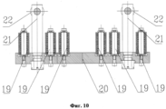
Фиг. 10. Пружинный блок с установленными на нем жаростойкими упругими элементами и ползунами с опорными роликами.FIG. 10. Spring unit with heat-resistant elastic elements and sliders with support rollers installed on it.
Патентуемый шиберный затвор 1 литейного ковша скользящего типа содержит (фиг. 1) корпус 2, подвижную каретку 3, тягу 16 подвижной каретки 3, привод затвора 18 со штоком 32, установленный в кронштейне 17, закрепленном на корпусе 2, неподвижную 4 и подвижную огнеупорные плиты 5 в металлических оболочках 30 с отверстиями, установленные соответственно в гнездах 27 корпуса 2 и каретки 3, поджатые одна к другой, подпружиненную опорную раму 6, стопор 14, фиксирующий опорную раму 6 на корпусе 2 в процессе работы шиберного затвора на рабочем ходу подвижной огнеупорной плиты 5, защитный экран 7, ковшевой стакан 10, установленный в корпусе 2 и стакан коллектор 9, установленный в подвижной каретке посредством байонетной гайки 8, два пружинных блока 20, установленные в опорной раме 6 по обе стороны от продольной оси затвора.
Конструкция содержит (фиг. 10) жаростойкие упругие элементы 19, количество которых составляет от 6 до 18 в зависимости от типоразмера шиберного затвора, установленные в пружинных блоках 20, две пары ползунов 21, с установленными на них роликами 22, закрепленными попарно на соответствующих пружинных блоках 20, имеющие, в свою очередь, возможность захода в пазы корпуса 15 при повороте опорной рамы на осях 24 относительно корпуса 2.The design contains (Fig. 10) heat-resistant
Подвижная тяга 16 подвижной каретки 3 соединена с приводом затвоpa 18 через подвижный ползун компенсатор 12 с конической разрезной стопорной гайкой 13.The
Подвижный ползун-компенсатор имеет сферическую поверхность 31, взаимодействующую с кронштейном 17 и гнездо 33 для захода штока привода 32 (Фиг. 1, 2, 3, 4, 9).The movable slider-compensator has a
В корпусе затвора 2 по обе стороны от продольной оси затвора попарно от соответствующих пазов корпуса 15 установлены направляющие 11 опорных роликов 22, закрепленные на корпусе затвора и взаимодействующие с опорными роликами 22 ползунов 21.In the
Направляющие 11 опорных роликов 22 имеют конические заходные фаски 25. Размер фаски по вертикали должен превышать максимально допустимый ход упругих элементов, а соотношение радиуса ролика 22 к вертикальной высоте фаски 25 должно находится в диапазоне 2,5-4,5 (Фиг. 6, 7).The
Фаски 26 направляющих 11 выполнены сферической формы, а соотношение радиуса ролика 22 к вертикальной высоте фаски должно находиться в диапазоне 2,5-4,5 (Фиг. 5, 7).The
Гнезда 27 под установку подвижной 5 и неподвижной плит 4 содержат как минимум 2 жаростойких магнита 23, заключенных в оболочку из немагнитного металла 28, расположенных по обе стороны от разливочного отверстия и имеющих возможность взаимодействовать с одним своим свободным торцом 29 с металлической 30 оболочкой огнеупорных плит (Фиг.7).
Подвижный ползун-компенсатор 12 имеет сферическую поверхность 31, взаимодействующую с кронштейном 17, и гнездо 33 для захода штока привода 32 (Фиг. 1, 2, 3, 4, 9).The movable slider-
Выполнение вышеприведенных конструктивных параметров фасок 25 направляющих 11 и роликов 22 в указанном диапазоне размеров позволяет обеспечить:The implementation of the above structural parameters of the
- Снижение усилия на приводе подвижной каретки 3 при совершении вспомогательного хода, до значений, не превышающих максимально необходимое усилие на рабочем ходу, что, в свою очередь, исключит необходимость увеличения мощности привода на стендах обслуживания.- Reducing the force on the drive of the
- Снижение вероятности заклинивания подвижной каретки 3.- Reducing the likelihood of jamming of the
Увеличение радиуса ролика 22 более рекомендуемого приведет к необходимости увеличения хода привода затвора и росту габаритов шиберного затвора в целом.An increase in the radius of the
Фаски 26 выполнены сферической формы, а соотношение радиуса ролика 22 к вертикальной высоте фаски должно находится в диапазоне 2,5-4,5 (Фиг. 5, 7).
Выполнение вышеприведенных конструктивных параметров фасок 26 направляющих 11 и роликов 22 в указанном диапазоне размеров позволяет обеспечить:The implementation of the above structural parameters of the
- Снижение усилия на приводе подвижной каретки 3 при совершении вспомогательного хода до значений, не превышающих максимально необходимое усилие на рабочем ходу, что, в свою очередь, исключит необходимость увеличения мощности привода на стендах обслуживания.- Reducing the force on the drive of the
- Снижение вероятности заклинивания подвижной каретки 3.- Reducing the likelihood of jamming of the
Увеличение радиуса ролика 22 более рекомендуемого приведет к необходимости увеличения хода привода затвора и росту габаритов шиберного затвора в целом.An increase in the radius of the
Корпус 2 и подвижная каретка 3 шиберного затвора содержат гнезда 27 под установку подвижной 5 и неподвижной 4 огнеупорных плит.The
Гнезда 27 содержат как минимум 2 жаростойких магнита 23, заключенные в оболочку из немагнитного металла 28 (например, из бронзовых сплавов), расположенных по обе стороны от разливочного отверстия и имеющих возможность взаимодействовать с одним своим свободным торцом 29 с металлической оболочкой огнеупорных плит 30 (фиг. 8, 9).
Патентуемая конструкция шиберного затвора работает следующим образом.The patented design of the slide gate operates as follows.
Установка шиберного затвора и замена огнеупоров производится в горизонтальном положении ковша на специальном стенде обслуживания, затвор на днище ковша при этом располагается приводом 18 вертикально вверх или вниз. В исходном состоянии шиберный затвор не укомплектован ковшевым стаканом 10, стаканом-коллектором, байонетной гайкой, плитами, приводом затвора.Installation of the slide gate and replacement of refractories is carried out in the horizontal position of the bucket on a special service stand, the shutter on the bottom of the bucket is located with the
Корпус затвора 2 закрепляется болтами на днище ковша и опорная рама 6 с подвижной кареткой 3 проворачивается оператором на осях 15 для доступа к гнездам 27. Ковшевой стакан 10 устанавливается на огнеупорном мертеле в корпус 2, неподвижная огнеупорная плита 4 устанавливаются в гнездо 27 корпуса 2, стык ковшевого стакана 10 и огнеупорной плиты 4 герметизируется огнеупорным мертелем.The
От выпадания из гнезда 27 и смещения плита 4 удерживается магнитами 23 за металлическую обечайку плиты 30, что, в свою очередь, предохраняет слой мертеля от разрушения до его затвердевания.From falling out of the
Подвижная огнеупорная плита 5 устанавливается в подвижную каретку 3.The movable refractory plate 5 is installed in the
Привод затвора 18 устанавливается в кронштейн 17, при этом шток привода 32 входит в гнездо 33 на ползуне компенсаторе 12. После этого опорная рама 6 с подвижной кареткой 3 проворачивается оператором на осях 15 до захода роликов 22 ползунов 21 в соответствующие пазы корпуса 2 и шиберный затвор закрывается по аналогии с книжкой.The
Стопор 14 перемещается в положение, позволяющее перемещать опорную раму совместно с подвижной кареткой и под действием привода опорные ролики 22 подпружиненных ползунов 21 заходят на направляющие 11, первоначально гарантированно касаясь заходных фасок направляющих 25 и 26, благодаря заданным конструктивным параметрам.The
В процессе захода роликов по фаскам на направляющие два пружинных блока 20, установленные в опорной раме, поднимаются вместе с ползунами и поджимают пружинные элементы на величину рабочего хода, определяемого как разница между верхней поверхностью направляющей 11 и нижней точкой ролика 22. После окончания вспомогательного хода привода ролики 22 втянуты на направляющие 11, рабочее усилие прижима плит создано.In the process of the rollers entering along the chamfers onto the guides, two spring blocks 20 installed in the support frame are lifted together with the sliders and compress the spring elements by the size of the stroke, defined as the difference between the upper surface of the
Одновременно с началом захода роликов на направляющие начинают соприкасаться поверхности огнеупорных плит, при этом усилие привода не должно превышать усилие привода, необходимое на рабочем ходу затвора, и благодаря наличию заходных фасок с заданными параметрами обеспечивается плавная передача усилия пружин на плиты и уменьшается риск повреждения огнеупорных плит.Simultaneously with the start of the approach of the rollers to the guides, the surfaces of the refractory plates begin to touch, while the drive force should not exceed the drive force required on the shutter stroke, and due to the presence of lead-in chamfers with the specified parameters, the force of the springs on the plates is smoothly transferred and the risk of damage to the refractory plates .
Стопор 14 возвращается в рабочее положение и оператором совершается несколько контрольных перемещений подвижной каретки на рабочем ходу. При этом сферическая поверхность 31 ползуна компенсатора скользит по внутренней поверхности кронштейна 17 и направляет тягу 16, минимизируя силы трения, возникающие между тягой 16 и корпусом.The
Если при полностью втянутом штоке 32 привода 18 отверстия огнеупорных плит 4, 5 не совмещены более чем на 2 мм, контргайка 13 освобождается, ползун-компенсатор 12 проворачивается на резьбе тяги 16 на нужное количество оборотов и снова фиксируется контргайкой 13.If, when the
После регулировки привода устанавливается стакан-коллектор 9 и фиксируется байонетной гайкой 8. Стык стакан-коллектор 9 и огнеупорной плиты 5 герметизируется огнеупорным мертелем. От выпадания из гнезда 27 и смещения плита 5 удерживается магнитами 23 за металлическую обечайку плиты 30, что, в свою очередь, предохраняет слой мертеля от разрушения до его затвердевания. Далее устанавливается защитный экран 7, служащий для защиты затвора от теплового излучения и брызг металла.After adjusting the drive, a
Разборка и открытие затвора для замены огнеупорных частей после эксплуатации происходит в обратном порядке.Disassembly and opening of the shutter to replace refractory parts after use occurs in the reverse order.
После приведения затвора в рабочее состояние в канал затвора при закрытом отверстии верхней плиты 4 засыпается технологическая стартовая смесь и заливается жидкий металл. При совмещении отверстий плит 4, 5 стартовая смесь высыпается и происходит разливка жидкого металла.After bringing the shutter into working condition, the shutter channel is filled with the technological starting mixture and the liquid metal is poured into the shutter channel with the closed hole of the
С помощью привода 18 происходит управление скоростью разливки металла путем частичного (дросселирование) или полного перекрытия разливочных отверстий. Точная центровка отверстий огнеупорных плит 4, 5 обеспечивает нужную точность дозирования металла, что особенно важно при применении систем автоматизации управления потоком разливаемого металла.Using the
Направляющие (планки) 11 и ролики 22 выполнены из специальных сплавов, обеспечивающих минимальный абразивный износ при высоких температурах и обеспечивают стабильное, плавное открытие затвора, долговечность конструкции.Guides (slats) 11 and
Проведенная заявителем апробация патентуемого шиберного затвора подтверждает, что его использование в металлургическом производстве позволяет:The applicant tested the patented slide gate confirms that its use in the metallurgical industry allows you to:
- обеспечить точную центровку (позиционирование) отверстий огнеупорных плит независимо от точности изготовления и износа деталей затвора, тем самым разработанная конструкция позволяет обеспечить требуемую скорость разливки металла при совмещении отверстий шиберных плит, особенно при старте разливки, обеспечить требуемую точность дозирования при применении средств автоматического управления ходом разливки металла из шиберного затвора, снизить скорость размыва огнеупорного материала шиберных плит в районе отверстия в процессе разливки;- to ensure accurate alignment (positioning) of the holes of the refractory plates regardless of the accuracy of manufacture and wear of the valve parts, thereby the developed design allows us to provide the required speed of metal casting when combining the openings of the slide plates, especially when starting casting, to ensure the required metering accuracy when using automatic means of control pouring metal from a slide gate, reduce the rate of erosion of the refractory material of the slide plates in the area of the hole during decomposition Application;
- существенно повысить экономическую эффективность получения высококачественного металла в процессе выплавки стали;- significantly increase the economic efficiency of obtaining high-quality metal in the process of steelmaking;
Исследования научно-технической, патентной и реферативной информации, а также проведенные экспериментальные исследования подтверждают новизну и высокую технико-экономическую эффективность реализации в металлургическом производстве патентуемого шиберного затвора и несомненные технологические и эксплуатационные преимущества разработанной конструкции шиберного затвора по сравнению с известными конструкциями аналогичного назначения.Research of scientific, technical, patent and abstract information, as well as experimental studies, confirm the novelty and high technical and economic efficiency of the patented slide gate in metallurgical production and the undoubted technological and operational advantages of the developed slide gate design in comparison with the known designs of a similar purpose.
Высокая технико-экономическая эффективность опытного использования разработанного шиберного затвора подтверждают технологическую перспективность и коммерческую значимость настоящей разработки.The high technical and economic efficiency of the experimental use of the developed slide gate confirms the technological prospects and commercial significance of this development.
Claims (4)
Priority Applications (1)
| Application Number | Priority Date | Filing Date | Title |
|---|---|---|---|
| RU2013143008/02A RU2567419C2 (en) | 2013-09-23 | 2013-09-23 | Slide gate of foundry ladle |
Applications Claiming Priority (1)
| Application Number | Priority Date | Filing Date | Title |
|---|---|---|---|
| RU2013143008/02A RU2567419C2 (en) | 2013-09-23 | 2013-09-23 | Slide gate of foundry ladle |
Publications (2)
| Publication Number | Publication Date |
|---|---|
| RU2013143008A RU2013143008A (en) | 2015-04-10 |
| RU2567419C2 true RU2567419C2 (en) | 2015-11-10 |
Family
ID=53282234
Family Applications (1)
| Application Number | Title | Priority Date | Filing Date |
|---|---|---|---|
| RU2013143008/02A RU2567419C2 (en) | 2013-09-23 | 2013-09-23 | Slide gate of foundry ladle |
Country Status (1)
| Country | Link |
|---|---|
| RU (1) | RU2567419C2 (en) |
Cited By (3)
| Publication number | Priority date | Publication date | Assignee | Title |
|---|---|---|---|---|
| RU172571U1 (en) * | 2016-10-31 | 2017-07-13 | Акционерное общество "ЕВРАЗ Объединенный Западно-Сибирский металлургический комбинат", АО "ЕВРАЗ ЗСМК" | GATE VALVE FOR STEEL FILLING DUCKS |
| RU2771730C2 (en) * | 2017-11-10 | 2022-05-11 | Везувиус Груп, С.А. | Assembly of bottom plate of gate, containing bayonet-free mounting of collector cup |
| US11638954B2 (en) | 2017-11-10 | 2023-05-02 | Vesuvius Group, S.A. | Bottom plate assembly comprising a bayonet free collector nozzle |
Citations (4)
| Publication number | Priority date | Publication date | Assignee | Title |
|---|---|---|---|---|
| RU2165824C1 (en) * | 1999-11-03 | 2001-04-27 | Открытое акционерное общество "Новолипецкий металлургический комбинат" | Flap-type sliding gate of casting ladle |
| RU2311260C1 (en) * | 2006-05-04 | 2007-11-27 | Общество с ограниченной ответственностью "РИАМЕТ" | Slide gate |
| CN201320604Y (en) * | 2008-11-17 | 2009-10-07 | 张付会 | Slide gate nozzle control mechanism |
| RU2010151424A (en) * | 2008-05-16 | 2012-06-27 | Кросаки Харима Корпорейшн (Jp) | SLATE FILLING DEVICE |
-
2013
- 2013-09-23 RU RU2013143008/02A patent/RU2567419C2/en active
Patent Citations (4)
| Publication number | Priority date | Publication date | Assignee | Title |
|---|---|---|---|---|
| RU2165824C1 (en) * | 1999-11-03 | 2001-04-27 | Открытое акционерное общество "Новолипецкий металлургический комбинат" | Flap-type sliding gate of casting ladle |
| RU2311260C1 (en) * | 2006-05-04 | 2007-11-27 | Общество с ограниченной ответственностью "РИАМЕТ" | Slide gate |
| RU2010151424A (en) * | 2008-05-16 | 2012-06-27 | Кросаки Харима Корпорейшн (Jp) | SLATE FILLING DEVICE |
| CN201320604Y (en) * | 2008-11-17 | 2009-10-07 | 张付会 | Slide gate nozzle control mechanism |
Cited By (3)
| Publication number | Priority date | Publication date | Assignee | Title |
|---|---|---|---|---|
| RU172571U1 (en) * | 2016-10-31 | 2017-07-13 | Акционерное общество "ЕВРАЗ Объединенный Западно-Сибирский металлургический комбинат", АО "ЕВРАЗ ЗСМК" | GATE VALVE FOR STEEL FILLING DUCKS |
| RU2771730C2 (en) * | 2017-11-10 | 2022-05-11 | Везувиус Груп, С.А. | Assembly of bottom plate of gate, containing bayonet-free mounting of collector cup |
| US11638954B2 (en) | 2017-11-10 | 2023-05-02 | Vesuvius Group, S.A. | Bottom plate assembly comprising a bayonet free collector nozzle |
Also Published As
| Publication number | Publication date |
|---|---|
| RU2013143008A (en) | 2015-04-10 |
Similar Documents
| Publication | Publication Date | Title |
|---|---|---|
| US3765579A (en) | Linearly movable gate mechanism | |
| SU1243611A3 (en) | Slide gate for metallurgical vessel | |
| US3567082A (en) | Casting installation | |
| RU2567419C2 (en) | Slide gate of foundry ladle | |
| JP4391022B2 (en) | Sliding gate valve for containers containing molten metal | |
| CN103451358A (en) | Slag-blocking steel-tapping device for revolving furnace | |
| JPH1060516A (en) | Slide gate valve of vessel for incorporating molten metal | |
| CN201385123Y (en) | Steel ladle sliding water gap device | |
| CN202610258U (en) | Slag stopping tapping device for converter | |
| GB1588676A (en) | Gate valve assembly for metallurgical vessels | |
| JP3009112U (en) | Device for connecting and exchanging the injection pipe to the container containing the molten metal | |
| RU2805409C1 (en) | Gate valve | |
| RU2311260C1 (en) | Slide gate | |
| US5388733A (en) | Slide gate valve having replaceable refractory valve plate assembly and method of replacing the same | |
| RU2805407C1 (en) | Gate valve | |
| RU2585583C2 (en) | Universal slide gate for batched casting of steel-pouring ladles | |
| JPH08117985A (en) | Surface pressure loading device of sliding gate | |
| WO2018145772A1 (en) | Improved flow channel device changer | |
| US5695674A (en) | Casting flow control device | |
| RU68942U1 (en) | CASTLE BUCKET VALVE AND DEVICE FOR CONVERTING THE VENTILATOR CARRIAGE TO THE SERVICE POSITION | |
| US4256291A (en) | Three-positions sliding gate valve | |
| RU2358833C1 (en) | Slide shutter of foundry ladle and device of carriage transfer of slide shutter into service position | |
| EP1097014B1 (en) | Apparatus and method for controlling the flow of molten metal | |
| RU56235U1 (en) | VALVE SHUTTER | |
| RU2104123C1 (en) | Slide gate of foundry ladle |