RU2565510C2 - System for fast and accurate quantitative evaluation of traumatic brain injury - Google Patents
System for fast and accurate quantitative evaluation of traumatic brain injury Download PDFInfo
- Publication number
- RU2565510C2 RU2565510C2 RU2012128871/08A RU2012128871A RU2565510C2 RU 2565510 C2 RU2565510 C2 RU 2565510C2 RU 2012128871/08 A RU2012128871/08 A RU 2012128871/08A RU 2012128871 A RU2012128871 A RU 2012128871A RU 2565510 C2 RU2565510 C2 RU 2565510C2
- Authority
- RU
- Russia
- Prior art keywords
- interest
- brain
- anatomical structure
- deformable model
- segmentation
- Prior art date
Links
Images
Classifications
-
- G—PHYSICS
- G06—COMPUTING; CALCULATING OR COUNTING
- G06T—IMAGE DATA PROCESSING OR GENERATION, IN GENERAL
- G06T7/00—Image analysis
- G06T7/10—Segmentation; Edge detection
- G06T7/149—Segmentation; Edge detection involving deformable models, e.g. active contour models
-
- G—PHYSICS
- G06—COMPUTING; CALCULATING OR COUNTING
- G06T—IMAGE DATA PROCESSING OR GENERATION, IN GENERAL
- G06T7/00—Image analysis
- G06T7/0002—Inspection of images, e.g. flaw detection
- G06T7/0012—Biomedical image inspection
-
- G—PHYSICS
- G06—COMPUTING; CALCULATING OR COUNTING
- G06T—IMAGE DATA PROCESSING OR GENERATION, IN GENERAL
- G06T2200/00—Indexing scheme for image data processing or generation, in general
- G06T2200/24—Indexing scheme for image data processing or generation, in general involving graphical user interfaces [GUIs]
-
- G—PHYSICS
- G06—COMPUTING; CALCULATING OR COUNTING
- G06T—IMAGE DATA PROCESSING OR GENERATION, IN GENERAL
- G06T2207/00—Indexing scheme for image analysis or image enhancement
- G06T2207/10—Image acquisition modality
- G06T2207/10072—Tomographic images
- G06T2207/10081—Computed x-ray tomography [CT]
-
- G—PHYSICS
- G06—COMPUTING; CALCULATING OR COUNTING
- G06T—IMAGE DATA PROCESSING OR GENERATION, IN GENERAL
- G06T2207/00—Indexing scheme for image analysis or image enhancement
- G06T2207/30—Subject of image; Context of image processing
- G06T2207/30004—Biomedical image processing
- G06T2207/30016—Brain
Abstract
Description
Уровень техникиState of the art
[0001] Черепно-мозговая травма (TBI) является одной из наиболее распространенных причин долгосрочной недееспособности. Патология некоторых подкорковых структур, например мозолистого тела, гиппокампа, мозжечка, таламуса и хвостатого ядра, связана с TBI. Таким образом, важно идентифицировать невропатологию у индивидуумов с TBI в трехмерном виде. Однако методологические проблемы препятствовали предыдущим исследованиям в предоставлении четкого шаблона структурной атрофии после TBI.[0001] Traumatic brain injury (TBI) is one of the most common causes of long-term disability. The pathology of some subcortical structures, such as the corpus callosum, hippocampus, cerebellum, thalamus, and caudate nucleus, is associated with TBI. Thus, it is important to identify neuropathology in individuals with TBI in three dimensions. However, methodological problems have hindered previous studies in providing a clear pattern of structural atrophy after TBI.
Сущность изобретенияSUMMARY OF THE INVENTION
[0002] Способ автоматической сегментации, выполняемый путем выбора деформируемой модели интересующей анатомической структуры, изображенной на объемном изображении, причем деформируемая модель образована из множества многоугольников, включающих в себя вершины и ребра, отображения деформируемой модели на дисплее, обнаружения характерной точки в интересующей анатомической структуре, соответствующей каждому из множества многоугольников, и адаптации деформируемой модели путем перемещения каждой из вершин в направлении соответствующих характерных точек, пока деформируемая модель не превратится в границу интересующей анатомической структуры, образующую сегментацию интересующей анатомической структуры.[0002] A method of automatic segmentation performed by selecting a deformable model of anatomical structure of interest shown in a three-dimensional image, wherein the deformable model is formed of a plurality of polygons including vertices and edges, displaying the deformable model on a display, detecting a characteristic point in the anatomical structure of interest, corresponding to each of the many polygons, and adapting the deformable model by moving each of the vertices in the direction of the corresponding x characteristic points until the deformable model turns into the boundary of the anatomical structure of interest, forming a segmentation of the anatomical structure of interest.
[0003] Система, содержащая процессор, выбирающий деформируемую модель интересующей анатомической структуры, изображенной на объемном изображении, причем деформируемая модель образована из множества многоугольников, включающих в себя вершины и ребра, и дисплей, отображающий деформируемую модель, причем процессор дополнительно обнаруживает характерную точку интересующей анатомической структуры, соответствующую каждому из множества многоугольников, чтобы деформировать деформируемую модель путем перемещения каждой из вершин в направлении соответствующих характерных точек, пока деформируемая модель не превратится в границу интересующей анатомической структуры, образующую сегментацию интересующей анатомической структуры.[0003] A system comprising a processor selecting a deformable model of an anatomical structure of interest shown in a three-dimensional image, the deformable model being formed from a plurality of polygons including vertices and edges, and a display showing the deformable model, the processor further detecting a characteristic point of the anatomical of interest structures corresponding to each of the many polygons to deform the deformable model by moving each of the vertices in the direction the corresponding characteristic points until the deformable model turns into the boundary of the anatomical structure of interest, forming a segmentation of the anatomical structure of interest.
[0004] Машиночитаемый запоминающий носитель, включающий в себя набор команд, исполняемых процессором. Набор команд, действующих с возможностью выбора деформируемой модели интересующей анатомической структуры, изображенной на объемном изображении, причем деформируемая модель образована из множества многоугольников, включающих в себя вершины и ребра, отображения деформируемого элемента на дисплее, обнаружения характерной точки в интересующей анатомической структуре, соответствующей каждому из множества многоугольников, и адаптации деформируемой модели путем перемещения каждой из вершин в направлении соответствующих характерных точек, пока деформируемая модель не превратится в границу интересующей анатомической структуры, образующую сегментацию интересующей анатомической структуры.[0004] A computer-readable storage medium including a set of instructions executed by a processor. A set of commands acting with the ability to select a deformable model of anatomical structure of interest shown in the three-dimensional image, the deformable model being made up of many polygons, including vertices and edges, display the deformable element on the display, detect a characteristic point in the anatomical structure of interest corresponding to each of sets of polygons, and adaptation of the deformable model by moving each of the vertices in the direction of the corresponding characteristic check until the deformable model turns into the boundary of the anatomical structure of interest, forming a segmentation of the anatomical structure of interest.
Краткое описание чертежейBrief Description of the Drawings
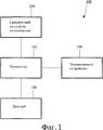
[0005] Фиг. 1 показывает схематическое изображение системы в соответствии с примерным вариантом осуществления.[0005] FIG. 1 shows a schematic illustration of a system in accordance with an exemplary embodiment.
[0006] Фиг. 2 показывает блок-схему алгоритма способа в соответствии с примерным вариантом осуществления.[0006] FIG. 2 shows a flowchart of a method in accordance with an exemplary embodiment.
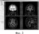
[0007] Фиг. 3 показывает снимок экрана деформируемой модели мозга, инициализированной на объемном изображении, отображенном в GUI.[0007] FIG. 3 shows a screen shot of a deformable brain model initialized in a 3D image displayed in a GUI.
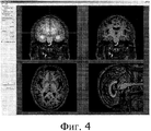
[0008] Фиг. 4 показывает снимок экрана деформируемой модели мозга из фиг. 3 после того, как она адаптирована к объемному изображению.[0008] FIG. 4 shows a screen shot of a deformable brain model from FIG. 3 after it is adapted to the three-dimensional image.
Подробное описаниеDetailed description
[0009] Примерные варианты осуществления можно дополнительно воспринимать со ссылкой на нижеследующее описание и прилагаемые чертежи, на которых на одинаковые элементы ссылаются одинаковыми номерами ссылок. Примерные варианты осуществления относятся к системе и способу сегментации структур мозга. В частности, примерные варианты осуществления формируют деформируемую модель структуры мозга, которую можно адаптировать к объемному изображению, такому как MRI (томограмма). Однако специалистам в данной области техники станет понятно, что хотя примерные варианты осуществления описывают, в частности, сегментацию структур мозга, система и способ согласно настоящему изобретению могут использоваться для сегментации любой анатомической трехмерной структуры на объемном изображении, например MRI и/или эхограмме.[0009] Exemplary embodiments may be further understood with reference to the following description and the accompanying drawings, in which like elements are referenced by the same reference numbers. Exemplary embodiments relate to a system and method for segmenting brain structures. In particular, exemplary embodiments form a deformable model of the structure of the brain that can be adapted to a three-dimensional image, such as an MRI (tomogram). However, it will be understood by those skilled in the art that although exemplary embodiments describe, in particular, the segmentation of brain structures, the system and method of the present invention can be used to segment any anatomical three-dimensional structure in a three-dimensional image, such as an MRI and / or echogram.
[0010] Как показано на фиг. 1, система 100 в соответствии с примерным вариантом осуществления сегментирует трехмерную структуру мозга, например мозолистое тело, гиппокамп, мозжечок, таламус и хвостатое ядро, в объемном изображении, таком как MRI или эхограмма. Система 100 содержит процессор 102, который способен к адаптации деформируемой модели структуры мозга на основе особенностей структуры в изображении. Деформируемая модель выбирается из базы данных моделей, сохраненной в запоминающем устройстве 108. Графический интерфейс 104 пользователя используется для ввода пользовательских предпочтений, для определения объема структуры мозга, для отображения деформации структуры мозга, для просмотра конкретной части структуры мозга и т.д. Входные данные, ассоциированные с графическим интерфейсом пользователя, вводятся посредством, например, мыши, сенсорного дисплея и/или клавиатуры. Сегментация структуры мозга, объемное изображение и варианты выбора для пользователя в графическом интерфейсе 104 пользователя отображаются на дисплее 106. Запоминающее устройство 108 может быть любым известным типом машиночитаемого запоминающего носителя. Специалистам в данной области техники станет понятно, что система 100 является, например, персональным компьютером, сервером или любым другим средством обработки.[0010] As shown in FIG. 1, a
[0011] Фиг. 2 показывает способ 200 в соответствии с примерным вариантом осуществления, в котором система 100 сегментирует структуру мозга, чтобы идентифицировать деформации в структуре мозга. Способ 200 включает в себя выбор деформируемой модели интересующей структуры мозга из базы данных моделей структур, сохраненной в запоминающем устройстве 108, на этапе 210. В примерном варианте осуществления деформируемая модель автоматически выбирается процессором 102 путем сравнения особенностей интересующей структуры мозга на объемном изображении с моделями структур в базе данных. В другом примерном варианте осуществления деформируемая модель вручную выбирается пользователем, просматривающим базу данных для идентификации деформируемой модели, которая больше всего похожа на интересующую структуру мозга. База данных моделей структур может включать в себя модели структур из исследований структуры мозга и/или результатов сегментации от предыдущих пациентов.[0011] FIG. 2 shows a method 200 in accordance with an exemplary embodiment in which a
[0012] На этапе 220 деформируемая модель отображается на дисплее 106, как показано на фиг. 3. Деформируемая модель должна отображаться как новое изображение и/или отображаться поверх объемного изображения. Деформируемая модель образуется из поверхностной сетки, включающей в себя множество многоугольников треугольной формы, причем каждый многоугольник треугольной формы дополнительно включает в себя три вершины и ребра. Однако специалистам в данной области техники станет понятно, что поверхностная сетка может включать в себя многоугольники иных форм. Деформируемая модель размещается так, что вершины деформируемой модели размещаются как можно ближе к границе интересующей структуры. На этапе 230 каждому из треугольных многоугольников назначается функция оптимального обнаружения границы. Функция оптимального обнаружения границы на этапе 240 обнаруживает характерные точки вдоль границы интересующей структуры, чтобы каждый из треугольных многоугольников ассоциировался с характерной точкой. Характерные точки могут ассоциироваться с центрами каждого из треугольных многоугольников. Характерная точка, ассоциированная с каждым из треугольных многоугольников, может быть характерной точкой, которая является ближайшей к треугольному многоугольнику и/или соответствует треугольному многоугольнику по положению.[0012] At step 220, the deformable model is displayed on the
[0013] На этапе 250 каждый из треугольных многоугольников, ассоциированный с характерной точкой, перемещается в направлении ассоциированной характерной точки, так что вершины каждого из треугольных многоугольников перемещаются в направлении границы интересующей структуры, деформируя деформируемую модель для адаптации к интересующей структуре на объемном изображении. Деформируемая модель деформируется до тех пор, пока положение каждого из треугольных многоугольников не будет соответствовать положению ассоциированной характерной точки и/или вершины треугольного многоугольника не будут находиться, по существу, вдоль границы интересующей структуры, как показано на фиг. 4. Как только деформируемая модель деформируется так, что треугольные многоугольники соответствуют ассоциированным характерным точкам границы интересующей структуры, деформируемая модель становится адаптированной к интересующей структуре, так что деформированная деформируемая модель представляет сегментированную структуру интересующей структуры.[0013] At step 250, each of the triangular polygons associated with the characteristic point moves in the direction of the associated characteristic point, so that the vertices of each of the triangular polygons move in the direction of the boundary of the structure of interest, deforming the deformable model to adapt to the structure of interest in the three-dimensional image. The deformable model is deformed until the position of each of the triangular polygons corresponds to the position of the associated characteristic point and / or the vertices of the triangular polygon essentially along the boundary of the structure of interest, as shown in FIG. 4. Once the deformable model is deformed so that the triangular polygons correspond to the associated characteristic points of the boundary of the structure of interest, the deformable model becomes adapted to the structure of interest, so that the deformable deformable model represents the segmented structure of the structure of interest.
[0014] По завершении процесса сегментации пользователь на этапе 260 может ввести пользовательский ввод касательно сегментированной структуры мозга. Пользовательский ввод можно ввести через графический интерфейс 104 пользователя, выбирая вариант выбора пользователя, который может отображаться в графическом интерфейсе 104 пользователя. Например, пользователь может выбрать увеличение и/или масштабирование конкретной части отображенных изображений, изменение вида конкретного изображения, определение интересующих параметров (например, объем сегментированной структуры, кривизна в некоторой точке), идентификацию деформации в сегментированной структуре и т.д. Другие варианты выбора могут включать в себя сохранение сегментированной структуры и/или соответствующих объемных изображений в базе данных деформируемых моделей или вызов ранее сохраненных сегментированных структур из базы данных с целью сравнения. Специалистам в данной области техники станет понятно, что сегментированные структуры и/или соответствующие объемные изображения также могут сохраняться в файлах пациентов для упрощения анализа структурной атрофии у пациентов с TBI.[0014] Upon completion of the segmentation process, the user may enter user input at 260 at a segmented brain structure. User input can be entered through the
[0015] Пользователь может захотеть определить объем и/или кривизну сегментированной структуры, чтобы оценить изменения в участке мозга. Такие параметры могут быть особенно полезны в увязывании прошлого воздействия TBI на текущие устойчивые жалобы, нарушения и недееспособность. К тому же здоровые структуры мозга известны как симметричные относительно срединной сагиттальной плоскости, так что левое и правое полушария мозга являются зеркальными изображениями друг друга. Таким образом, в здоровом мозге вершина в одном полушарии мозга - например, в левом полушарии - должна зеркально отображаться в другом полушарии - правом полушарии. Однако TBI по большей части является асимметричным заболеванием. Таким образом, отклонения от средних значений вершин представляют расхождения, которые указывают серьезность деформации интересующих структур мозга. Пользователь поэтому может выбрать просмотр отклонений от средних значений вершин в сегментированной структуре. В дополнительном варианте осуществления разные отклонения могут кодироваться цветом для простой визуализации и интерпретации результатов.[0015] The user may want to determine the volume and / or curvature of the segmented structure in order to evaluate changes in a portion of the brain. Such parameters can be especially useful in linking the past impact of TBI on current persistent complaints, violations and incapacities. In addition, healthy brain structures are known to be symmetrical about the median sagittal plane, so that the left and right hemispheres of the brain are mirror images of each other. Thus, in a healthy brain, the apex in one hemisphere of the brain - for example, in the left hemisphere - should be mirrored in the other hemisphere - the right hemisphere. However, TBI is for the most part an asymmetric disease. Thus, deviations from the average values of the vertices represent discrepancies that indicate the severity of the deformation of the brain structures of interest. The user can therefore choose to view deviations from the average values of the vertices in the segmented structure. In a further embodiment, different deviations may be color coded for easy visualization and interpretation of the results.
[0016] На этапе 270 процессор 102 формирует ответ на пользовательский ввод, введенный на этапе 260. Например, если пользователь запросил объем сегментированной структуры, то процессор 102 вычислит объем и отобразит объем на дисплее 106. Если пользователь указал, что пользователь хотел бы увеличить конкретную часть объемного изображения и/или сегментированного органа, то процессор 102 сформирует и отобразит увеличенный вид конкретной нужной части. В другом примере, если пользователь указал, что пользователь хотел бы идентифицировать деформации в сегментированной структуре, то процессор 102 идентифицирует срединную сагиттальную плоскость, идентифицирует отклонения в средних значениях вершин между левым и правым полушариями и отобразит деформации на дисплее 106. Как описано выше, разные отклонения могут обозначаться цветом. Этапы 260-270 могут повторяться по желанию, пока пользователь не выберет все нужные варианты выбора в отношении сегментированной структуры мозга.[0016] At step 270, the
[0017] Специалистам в данной области техники будет очевидно, что различные модификации и изменения можно внести в структуру и методологию, описанную в этом документе. Таким образом, подразумевается, что настоящее раскрытие изобретения охватывает любые модификации и изменения при условии, что они подпадают под объем прилагаемой формулы изобретения и ее эквивалентов.[0017] It will be apparent to those skilled in the art that various modifications and changes can be made to the structure and methodology described in this document. Thus, it is intended that the present disclosure cover any modifications and changes provided that they come within the scope of the appended claims and their equivalents.
[0018] Также отметим, что формула изобретения может включать в себя знаки/цифры ссылок в соответствии с Правилом 6.2(b) PCT. Однако настоящая формула изобретения не должна считаться ограниченной примерными вариантами осуществления, соответствующими знакам/цифрам ссылок.[0018] It is also noted that the claims may include reference characters / numbers in accordance with PCT Rule 6.2 (b). However, the present claims should not be deemed limited by exemplary embodiments corresponding to the signs / numbers of the links.
Claims (12)
выбирают в качестве интересующей анатомической структуры структуру мозга, являющуюся симметричной относительно срединной сагиттальной плоскости в здоровом мозге;
выбирают (210) деформируемую модель интересующей анатомической структуры, изображенной на объемном изображении мозга, причем деформируемая модель образована из множества многоугольников, включающих в себя вершины и ребра;
отображают (220) деформируемую модель на дисплее (106);
обнаруживают (240) характерную точку интересующей анатомической структуры, соответствующую каждому из множества многоугольников;
адаптируют (250) деформируемую модель путем перемещения каждого из многоугольников в направлении соответствующих характерных точек, пока деформируемая модель не превратится в границу интересующей анатомической структуры, образующую сегментацию интересующей анатомической структуры;
идентифицируют деформации в сегментации интересующей анатомической структуры посредством i) идентификации срединной сагиттальной плоскости данного мозга и ii) определения для интересующей анатомической структуры отклонений в средних значениях вершин между левой и правой полусферами данного мозга относительно срединной сагиттальной плоскости данного мозга, так чтобы указать серьезность деформации интересующей анатомической структуры; и отображают идентифицированные деформации.1. A method for automatic segmentation of brain structures, comprising stages in which:
choose, as the anatomical structure of interest, a brain structure that is symmetrical with respect to the median sagittal plane in a healthy brain;
choose (210) a deformable model of the anatomical structure of interest depicted in the three-dimensional image of the brain, the deformable model formed of many polygons, including vertices and edges;
display (220) the deformable model on the display (106);
detect (240) the characteristic point of the anatomical structure of interest corresponding to each of the many polygons;
adapt (250) the deformable model by moving each of the polygons in the direction of the corresponding characteristic points until the deformable model turns into the boundary of the anatomical structure of interest, forming a segmentation of the anatomical structure of interest;
identify strains in the segmentation of the anatomical structure of interest by i) identifying the median sagittal plane of the brain and ii) determining for the anatomical structure of interest the deviations in the average values of the vertices between the left and right hemispheres of the brain relative to the median sagittal plane of the brain, so as to indicate the severity of the deformation of the anatomical of interest structure; and display the identified deformations.
принимают (260) пользовательский ввод через графический интерфейс (104), причем пользовательский ввод выбирает вариант выбора в отношении сегментации.4. The method of claim 1, further comprising the step of:
receiving (260) user input via a graphical interface (104), wherein the user input selects a choice regarding segmentation.
процессор (102), выбирающий в качестве интересующей анатомической структуры структуру мозга, являющуюся симметричной относительно срединной сагиттальной плоскости в здоровом мозге, и выбирающий деформируемую модель интересующей анатомической структуры, изображенной на объемном изображении мозга, причем деформируемая модель образована из множества многоугольников, включающих в себя вершины и ребра;
дисплей (106), отображающий деформируемую модель,
причем процессор (102) дополнительно обнаруживает характерную точку интересующей анатомической структуры, соответствующую каждому из множества многоугольников, чтобы деформировать деформируемую модель путем перемещения каждой из вершин в направлении соответствующих характерных точек, пока деформируемая модель не превратится в границу интересующей анатомической структуры, образующую сегментацию интересующей анатомической структуры;
причем процессор (102) дополнительно выполнен с возможностью идентификации деформаций в сегментации интересующей анатомической структуры посредством i) идентификации срединной сагиттальной плоскости данного мозга, ii) определения для интересующей анатомической структуры отклонений в средних значениях вершин между левой и правой полусферами данного мозга относительно срединной сагиттальной плоскости данного мозга, так чтобы указать серьезность деформации интересующей анатомической структуры.6. A system for automatic segmentation of brain structures, comprising:
a processor (102) that selects a brain structure that is symmetrical with respect to the median sagittal plane in a healthy brain as the anatomical structure of interest, and selects a deformable model of the anatomical structure of interest shown in the three-dimensional image of the brain, and the deformable model is composed of many polygons including vertices and ribs;
a display (106) showing the deformable model,
moreover, the processor (102) additionally detects a characteristic point of the anatomical structure of interest corresponding to each of the many polygons in order to deform the deformable model by moving each of the vertices in the direction of the corresponding characteristic points until the deformable model turns into the boundary of the anatomical structure of interest, forming a segmentation of the anatomical structure of interest ;
moreover, the processor (102) is additionally configured to identify deformations in the segmentation of the anatomical structure of interest by i) identifying the median sagittal plane of the brain, ii) determining for the anatomical structure of interest deviations in the average values of the vertices between the left and right hemispheres of the brain relative to the median sagittal plane of brain, so as to indicate the severity of the deformation of the anatomical structure of interest.
запоминающее устройство (108), хранящее базу данных структур, из которой выбирается деформируемая модель.7. The system of claim 6, further comprising:
a storage device (108) storing a database of structures from which a deformable model is selected.
графический интерфейс (104) пользователя, принимающий пользовательский ввод, который выбирает вариант выбора в отношении сегментации.9. The system of claim 6, further comprising:
a graphical user interface (104) receiving a user input that selects a selection regarding segmentation.
Applications Claiming Priority (3)
| Application Number | Priority Date | Filing Date | Title |
|---|---|---|---|
| US28521609P | 2009-12-10 | 2009-12-10 | |
| US61/285,216 | 2009-12-10 | ||
| PCT/IB2010/055246 WO2011070464A2 (en) | 2009-12-10 | 2010-11-17 | A system for rapid and accurate quantitative assessment of traumatic brain injury |
Publications (2)
| Publication Number | Publication Date |
|---|---|
| RU2012128871A RU2012128871A (en) | 2014-01-20 |
| RU2565510C2 true RU2565510C2 (en) | 2015-10-20 |
Family
ID=44022012
Family Applications (1)
| Application Number | Title | Priority Date | Filing Date |
|---|---|---|---|
| RU2012128871/08A RU2565510C2 (en) | 2009-12-10 | 2010-11-17 | System for fast and accurate quantitative evaluation of traumatic brain injury |
Country Status (7)
| Country | Link |
|---|---|
| US (1) | US9256951B2 (en) |
| EP (1) | EP2510500B1 (en) |
| JP (1) | JP5736386B2 (en) |
| CN (1) | CN102754125B (en) |
| BR (1) | BR112012013691A8 (en) |
| RU (1) | RU2565510C2 (en) |
| WO (1) | WO2011070464A2 (en) |
Families Citing this family (18)
| Publication number | Priority date | Publication date | Assignee | Title |
|---|---|---|---|---|
| JP5736386B2 (en) * | 2009-12-10 | 2015-06-17 | コーニンクレッカ フィリップス エヌ ヴェ | A rapid and accurate quantitative assessment system for traumatic brain injury |
| US9072489B2 (en) * | 2010-01-07 | 2015-07-07 | Hitachi Medical Corporation | Medical image diagnostic apparatus and medical image contour extraction processing method |
| EP2979241A1 (en) * | 2013-03-28 | 2016-02-03 | Koninklijke Philips N.V. | Improving symmetry in brain scans |
| CN104414680B (en) * | 2013-08-21 | 2017-06-13 | 深圳迈瑞生物医疗电子股份有限公司 | A kind of 3-D supersonic imaging method and system |
| US10043270B2 (en) | 2014-03-21 | 2018-08-07 | Koninklijke Philips N.V. | Image processing apparatus and method for segmenting a region of interest |
| CN110338841B (en) * | 2015-02-16 | 2022-04-15 | 深圳迈瑞生物医疗电子股份有限公司 | Three-dimensional imaging data display processing method and three-dimensional ultrasonic imaging method and system |
| WO2016169903A1 (en) * | 2015-04-23 | 2016-10-27 | Koninklijke Philips N.V. | Model-based segmentation of an anatomical structure |
| CN109688934A (en) | 2016-08-01 | 2019-04-26 | 戈尔丹斯医疗公司 | The opening of the blood-brain barrier of ultrasonic guidance |
| CN110383347B (en) | 2017-01-06 | 2023-11-07 | 皇家飞利浦有限公司 | Cortical deformity identification |
| CN109620407B (en) | 2017-10-06 | 2024-02-06 | 皇家飞利浦有限公司 | Treatment trajectory guidance system |
| US11288803B2 (en) * | 2017-10-09 | 2022-03-29 | Koninklijke Philips N.V. | Ablation result validation system |
| DE102017221720B3 (en) * | 2017-12-01 | 2019-02-07 | Siemens Healthcare Gmbh | Providing a patient model of a patient |
| WO2019180120A1 (en) | 2018-03-21 | 2019-09-26 | Koninklijke Philips N.V. | Medical radiology report validation and augmentation system |
| US20210000350A1 (en) | 2018-03-21 | 2021-01-07 | Koninklijke Philips N.V. | Neurological examination system |
| US20210004624A1 (en) | 2018-03-21 | 2021-01-07 | Koninklijke Philips N.V. | Incidental finding augmentation system for medical radiology |
| WO2020025560A1 (en) | 2018-07-30 | 2020-02-06 | Koninklijke Philips N.V. | Functional magnetic resonance imaging systems and methods |
| WO2020148247A2 (en) | 2019-01-14 | 2020-07-23 | Koninklijke Philips N.V. | Compartment-specific down-scaling of high-frequency conductivity to low-frequency conductivity for eeg |
| WO2021051184A1 (en) * | 2019-09-19 | 2021-03-25 | Prevu3D Technologies Inc. | Methods and systems for extracting data from virtual representations of three-dimensional visual scans |
Citations (4)
| Publication number | Priority date | Publication date | Assignee | Title |
|---|---|---|---|---|
| RU2291488C9 (en) * | 2002-06-24 | 2007-04-20 | Ренат Анатольевич Красноперов | Method for stereological examination of objects structural organization |
| US20070185544A1 (en) * | 2006-01-13 | 2007-08-09 | Vanderbilt University | System and methods of deep brain stimulation for post-operation patients |
| US20080279429A1 (en) * | 2005-11-18 | 2008-11-13 | Koninklijke Philips Electronics, N.V. | Method For Delineation of Predetermined Structures in 3D Images |
| RU2366475C2 (en) * | 2005-01-31 | 2009-09-10 | Чонгцинг Хайфу(Хифу)Текнолоджи Ко., Лтд | Therapy system based on focused ultrasound |
Family Cites Families (27)
| Publication number | Priority date | Publication date | Assignee | Title |
|---|---|---|---|---|
| US5920319A (en) * | 1994-10-27 | 1999-07-06 | Wake Forest University | Automatic analysis in virtual endoscopy |
| JP3111024B2 (en) | 1995-07-19 | 2000-11-20 | キヤノン株式会社 | Apparatus and method for manufacturing color filter, method for manufacturing display apparatus, and method for manufacturing apparatus provided with display apparatus |
| US6483506B1 (en) * | 2000-07-20 | 2002-11-19 | Sony Corporation | System and method for generating computer animated graphical images of a vascular structure attached to an anatomical structure |
| US7538764B2 (en) * | 2001-01-05 | 2009-05-26 | Interuniversitair Micro-Elektronica Centrum (Imec) | System and method to obtain surface structures of multi-dimensional objects, and to represent those surface structures for animation, transmission and display |
| ATE516846T1 (en) * | 2001-05-04 | 2011-08-15 | Univ Texas | APPARATUS AND METHOD FOR DELIVERING TRANSCRANIAL MAGNETIC STIMULATION |
| US20030036083A1 (en) | 2001-07-19 | 2003-02-20 | Jose Tamez-Pena | System and method for quantifying tissue structures and their change over time |
| US20030160786A1 (en) * | 2002-02-28 | 2003-08-28 | Johnson Richard K. | Automatic determination of borders of body structures |
| AU2003281649A1 (en) | 2002-07-19 | 2004-02-09 | Koninklijke Philips Electronics N.V. | Automated measurement of objects using deformable models |
| US8032202B2 (en) * | 2003-04-04 | 2011-10-04 | Hitachi Medical Corporation | Function image display method and device |
| EP1638459A2 (en) * | 2003-06-11 | 2006-03-29 | Case Western Reserve University | Computer-aided-design of skeletal implants |
| DE10357203B4 (en) | 2003-12-08 | 2018-09-20 | Siemens Healthcare Gmbh | Method and control device for operating a magnetic resonance tomography device and magnetic resonance tomography device |
| US8280482B2 (en) | 2004-04-19 | 2012-10-02 | New York University | Method and apparatus for evaluating regional changes in three-dimensional tomographic images |
| US7426318B2 (en) * | 2004-06-30 | 2008-09-16 | Accuray, Inc. | Motion field generation for non-rigid image registration |
| US7231076B2 (en) * | 2004-06-30 | 2007-06-12 | Accuray, Inc. | ROI selection in image registration |
| KR100680232B1 (en) | 2005-04-20 | 2007-02-08 | 이화여자대학교 산학협력단 | Method for analyzing hippocampus for aiding diagnosis of brain diseases and the recording media therein readable by computer |
| US20060277466A1 (en) * | 2005-05-13 | 2006-12-07 | Anderson Thomas G | Bimodal user interaction with a simulated object |
| US7680312B2 (en) | 2005-07-13 | 2010-03-16 | Siemens Medical Solutions Usa, Inc. | Method for knowledge based image segmentation using shape models |
| US20090220136A1 (en) * | 2006-02-03 | 2009-09-03 | University Of Florida Research Foundation | Image Guidance System for Deep Brain Stimulation |
| WO2008152555A2 (en) * | 2007-06-12 | 2008-12-18 | Koninklijke Philips Electronics N.V. | Anatomy-driven image data segmentation |
| US8135189B2 (en) * | 2007-10-03 | 2012-03-13 | Siemens Medical Solutions Usa, Inc. | System and method for organ segmentation using surface patch classification in 2D and 3D images |
| JP2011504115A (en) * | 2007-10-18 | 2011-02-03 | ザ ユニバーシティ オブ ノース カロライナ アット チャペル ヒル | Method, system and computer-readable medium for mapping a region of a model of an object containing anatomical structures from a single image data to an image used for diagnostic or therapeutic intervention |
| WO2009065079A2 (en) | 2007-11-14 | 2009-05-22 | The Regents Of The University Of California | Longitudinal registration of anatomy in magnetic resonance imaging |
| US20090128553A1 (en) * | 2007-11-15 | 2009-05-21 | The Board Of Trustees Of The University Of Illinois | Imaging of anatomical structures |
| US8160345B2 (en) * | 2008-04-30 | 2012-04-17 | Otismed Corporation | System and method for image segmentation in generating computer models of a joint to undergo arthroplasty |
| JP5562598B2 (en) * | 2008-10-24 | 2014-07-30 | 株式会社東芝 | Image display apparatus, image display method, and magnetic resonance imaging apparatus |
| US9259290B2 (en) * | 2009-06-08 | 2016-02-16 | MRI Interventions, Inc. | MRI-guided surgical systems with proximity alerts |
| JP5736386B2 (en) * | 2009-12-10 | 2015-06-17 | コーニンクレッカ フィリップス エヌ ヴェ | A rapid and accurate quantitative assessment system for traumatic brain injury |
-
2010
- 2010-11-17 JP JP2012542644A patent/JP5736386B2/en active Active
- 2010-11-17 US US13/514,713 patent/US9256951B2/en active Active
- 2010-11-17 WO PCT/IB2010/055246 patent/WO2011070464A2/en active Application Filing
- 2010-11-17 BR BR112012013691A patent/BR112012013691A8/en not_active Application Discontinuation
- 2010-11-17 EP EP10801697.3A patent/EP2510500B1/en active Active
- 2010-11-17 RU RU2012128871/08A patent/RU2565510C2/en active
- 2010-11-17 CN CN201080055131.XA patent/CN102754125B/en active Active
Patent Citations (4)
| Publication number | Priority date | Publication date | Assignee | Title |
|---|---|---|---|---|
| RU2291488C9 (en) * | 2002-06-24 | 2007-04-20 | Ренат Анатольевич Красноперов | Method for stereological examination of objects structural organization |
| RU2366475C2 (en) * | 2005-01-31 | 2009-09-10 | Чонгцинг Хайфу(Хифу)Текнолоджи Ко., Лтд | Therapy system based on focused ultrasound |
| US20080279429A1 (en) * | 2005-11-18 | 2008-11-13 | Koninklijke Philips Electronics, N.V. | Method For Delineation of Predetermined Structures in 3D Images |
| US20070185544A1 (en) * | 2006-01-13 | 2007-08-09 | Vanderbilt University | System and methods of deep brain stimulation for post-operation patients |
Also Published As
| Publication number | Publication date |
|---|---|
| CN102754125B (en) | 2016-05-25 |
| US9256951B2 (en) | 2016-02-09 |
| WO2011070464A2 (en) | 2011-06-16 |
| RU2012128871A (en) | 2014-01-20 |
| JP2013513409A (en) | 2013-04-22 |
| US20120327075A1 (en) | 2012-12-27 |
| BR112012013691A8 (en) | 2017-11-07 |
| BR112012013691A2 (en) | 2017-10-10 |
| CN102754125A (en) | 2012-10-24 |
| EP2510500A2 (en) | 2012-10-17 |
| WO2011070464A3 (en) | 2011-08-04 |
| EP2510500B1 (en) | 2017-08-02 |
| JP5736386B2 (en) | 2015-06-17 |
Similar Documents
| Publication | Publication Date | Title |
|---|---|---|
| RU2565510C2 (en) | System for fast and accurate quantitative evaluation of traumatic brain injury | |
| US20200184646A1 (en) | Systems and methods for probablistic segmentation in anatomical image processing | |
| US10885392B2 (en) | Learning annotation of objects in image | |
| Kim et al. | Automated 3-D extraction and evaluation of the inner and outer cortical surfaces using a Laplacian map and partial volume effect classification | |
| Petitjean et al. | Assessment of myocardial function: a review of quantification methods and results using tagged MRI | |
| CN103717122A (en) | Ophthalmic diagnosis support apparatus and ophthalmic diagnosis support method | |
| US20120027277A1 (en) | Interactive iterative closest point algorithm for organ segmentation | |
| EP3657435A1 (en) | Apparatus for identifying regions in a brain image | |
| CN110264444A (en) | Damage detecting method and device based on weak segmentation | |
| RU2573740C2 (en) | Standard set of data for neuropsychic disorders | |
| ES2797907T3 (en) | Retinal Imaging | |
| US20160306023A1 (en) | System for measuring cortical thickness from mr scan information | |
| JP2007312837A (en) | Region extracting apparatus, region extracting method and program | |
| JP2019514471A (en) | Retina image processing | |
| JP2007164592A (en) | Modeling device, area extraction device and program | |
| Chitiboi et al. | Contour tracking and probabilistic segmentation of tissue phase mapping MRI | |
| KR102566183B1 (en) | Method for providing information on automatic pelvic measurement and apparatus using the same | |
| Mani et al. | An automated hybrid decoupled convolutional network for laceration segmentation and grading of retinal diseases using optical coherence tomography (OCT) images | |
| EP3712844A1 (en) | Method and system for fast assessment of brain change normality | |
| CN114078579A (en) | Histopathology reading mode learning system, method and terminal | |
| CN117455761A (en) | Automatic adjustment method for scale of digital pathological image in zooming process | |
| JP2021174120A (en) | Vector field information generation device, state determination support system, state determination support device, state prediction system, state prediction device, vector field information generation method, and program | |
| Hu | Multimodal 3-D segmentation of optic nerve head structures from spectral domain OCT volumes and color fundus photographs | |
| JP2019500692A (en) | Image processing for improved marker placement for linear image features |