RU2561785C2 - Heat-conducting cylinder installed with u-shaped rod-type pipeline and ring-shaped pipeline - Google Patents
Heat-conducting cylinder installed with u-shaped rod-type pipeline and ring-shaped pipeline Download PDFInfo
- Publication number
- RU2561785C2 RU2561785C2 RU2010144069/06A RU2010144069A RU2561785C2 RU 2561785 C2 RU2561785 C2 RU 2561785C2 RU 2010144069/06 A RU2010144069/06 A RU 2010144069/06A RU 2010144069 A RU2010144069 A RU 2010144069A RU 2561785 C2 RU2561785 C2 RU 2561785C2
- Authority
- RU
- Russia
- Prior art keywords
- heat
- fluid
- shaped
- conducting
- outlet
- Prior art date
Links
Images


Classifications
-
- F—MECHANICAL ENGINEERING; LIGHTING; HEATING; WEAPONS; BLASTING
- F28—HEAT EXCHANGE IN GENERAL
- F28D—HEAT-EXCHANGE APPARATUS, NOT PROVIDED FOR IN ANOTHER SUBCLASS, IN WHICH THE HEAT-EXCHANGE MEDIA DO NOT COME INTO DIRECT CONTACT
- F28D20/00—Heat storage plants or apparatus in general; Regenerative heat-exchange apparatus not covered by groups F28D17/00 or F28D19/00
- F28D20/0052—Heat storage plants or apparatus in general; Regenerative heat-exchange apparatus not covered by groups F28D17/00 or F28D19/00 using the ground body or aquifers as heat storage medium
-
- F—MECHANICAL ENGINEERING; LIGHTING; HEATING; WEAPONS; BLASTING
- F24—HEATING; RANGES; VENTILATING
- F24T—GEOTHERMAL COLLECTORS; GEOTHERMAL SYSTEMS
- F24T10/00—Geothermal collectors
- F24T10/10—Geothermal collectors with circulation of working fluids through underground channels, the working fluids not coming into direct contact with the ground
- F24T10/13—Geothermal collectors with circulation of working fluids through underground channels, the working fluids not coming into direct contact with the ground using tube assemblies suitable for insertion into boreholes in the ground, e.g. geothermal probes
-
- F—MECHANICAL ENGINEERING; LIGHTING; HEATING; WEAPONS; BLASTING
- F28—HEAT EXCHANGE IN GENERAL
- F28D—HEAT-EXCHANGE APPARATUS, NOT PROVIDED FOR IN ANOTHER SUBCLASS, IN WHICH THE HEAT-EXCHANGE MEDIA DO NOT COME INTO DIRECT CONTACT
- F28D1/00—Heat-exchange apparatus having stationary conduit assemblies for one heat-exchange medium only, the media being in contact with different sides of the conduit wall, in which the other heat-exchange medium is a large body of fluid, e.g. domestic or motor car radiators
- F28D1/02—Heat-exchange apparatus having stationary conduit assemblies for one heat-exchange medium only, the media being in contact with different sides of the conduit wall, in which the other heat-exchange medium is a large body of fluid, e.g. domestic or motor car radiators with heat-exchange conduits immersed in the body of fluid
- F28D1/04—Heat-exchange apparatus having stationary conduit assemblies for one heat-exchange medium only, the media being in contact with different sides of the conduit wall, in which the other heat-exchange medium is a large body of fluid, e.g. domestic or motor car radiators with heat-exchange conduits immersed in the body of fluid with tubular conduits
- F28D1/047—Heat-exchange apparatus having stationary conduit assemblies for one heat-exchange medium only, the media being in contact with different sides of the conduit wall, in which the other heat-exchange medium is a large body of fluid, e.g. domestic or motor car radiators with heat-exchange conduits immersed in the body of fluid with tubular conduits the conduits being bent, e.g. in a serpentine or zig-zag
- F28D1/0472—Heat-exchange apparatus having stationary conduit assemblies for one heat-exchange medium only, the media being in contact with different sides of the conduit wall, in which the other heat-exchange medium is a large body of fluid, e.g. domestic or motor car radiators with heat-exchange conduits immersed in the body of fluid with tubular conduits the conduits being bent, e.g. in a serpentine or zig-zag the conduits being helically or spirally coiled
-
- F—MECHANICAL ENGINEERING; LIGHTING; HEATING; WEAPONS; BLASTING
- F28—HEAT EXCHANGE IN GENERAL
- F28D—HEAT-EXCHANGE APPARATUS, NOT PROVIDED FOR IN ANOTHER SUBCLASS, IN WHICH THE HEAT-EXCHANGE MEDIA DO NOT COME INTO DIRECT CONTACT
- F28D1/00—Heat-exchange apparatus having stationary conduit assemblies for one heat-exchange medium only, the media being in contact with different sides of the conduit wall, in which the other heat-exchange medium is a large body of fluid, e.g. domestic or motor car radiators
- F28D1/02—Heat-exchange apparatus having stationary conduit assemblies for one heat-exchange medium only, the media being in contact with different sides of the conduit wall, in which the other heat-exchange medium is a large body of fluid, e.g. domestic or motor car radiators with heat-exchange conduits immersed in the body of fluid
- F28D1/04—Heat-exchange apparatus having stationary conduit assemblies for one heat-exchange medium only, the media being in contact with different sides of the conduit wall, in which the other heat-exchange medium is a large body of fluid, e.g. domestic or motor car radiators with heat-exchange conduits immersed in the body of fluid with tubular conduits
- F28D1/047—Heat-exchange apparatus having stationary conduit assemblies for one heat-exchange medium only, the media being in contact with different sides of the conduit wall, in which the other heat-exchange medium is a large body of fluid, e.g. domestic or motor car radiators with heat-exchange conduits immersed in the body of fluid with tubular conduits the conduits being bent, e.g. in a serpentine or zig-zag
- F28D1/0475—Heat-exchange apparatus having stationary conduit assemblies for one heat-exchange medium only, the media being in contact with different sides of the conduit wall, in which the other heat-exchange medium is a large body of fluid, e.g. domestic or motor car radiators with heat-exchange conduits immersed in the body of fluid with tubular conduits the conduits being bent, e.g. in a serpentine or zig-zag the conduits having a single U-bend
-
- F—MECHANICAL ENGINEERING; LIGHTING; HEATING; WEAPONS; BLASTING
- F28—HEAT EXCHANGE IN GENERAL
- F28F—DETAILS OF HEAT-EXCHANGE AND HEAT-TRANSFER APPARATUS, OF GENERAL APPLICATION
- F28F13/00—Arrangements for modifying heat-transfer, e.g. increasing, decreasing
- F28F2013/005—Thermal joints
-
- F—MECHANICAL ENGINEERING; LIGHTING; HEATING; WEAPONS; BLASTING
- F28—HEAT EXCHANGE IN GENERAL
- F28F—DETAILS OF HEAT-EXCHANGE AND HEAT-TRANSFER APPARATUS, OF GENERAL APPLICATION
- F28F2270/00—Thermal insulation; Thermal decoupling
-
- F—MECHANICAL ENGINEERING; LIGHTING; HEATING; WEAPONS; BLASTING
- F28—HEAT EXCHANGE IN GENERAL
- F28F—DETAILS OF HEAT-EXCHANGE AND HEAT-TRANSFER APPARATUS, OF GENERAL APPLICATION
- F28F2275/00—Fastening; Joining
- F28F2275/02—Fastening; Joining by using bonding materials; by embedding elements in particular materials
-
- Y—GENERAL TAGGING OF NEW TECHNOLOGICAL DEVELOPMENTS; GENERAL TAGGING OF CROSS-SECTIONAL TECHNOLOGIES SPANNING OVER SEVERAL SECTIONS OF THE IPC; TECHNICAL SUBJECTS COVERED BY FORMER USPC CROSS-REFERENCE ART COLLECTIONS [XRACs] AND DIGESTS
- Y02—TECHNOLOGIES OR APPLICATIONS FOR MITIGATION OR ADAPTATION AGAINST CLIMATE CHANGE
- Y02E—REDUCTION OF GREENHOUSE GAS [GHG] EMISSIONS, RELATED TO ENERGY GENERATION, TRANSMISSION OR DISTRIBUTION
- Y02E10/00—Energy generation through renewable energy sources
- Y02E10/10—Geothermal energy
-
- Y—GENERAL TAGGING OF NEW TECHNOLOGICAL DEVELOPMENTS; GENERAL TAGGING OF CROSS-SECTIONAL TECHNOLOGIES SPANNING OVER SEVERAL SECTIONS OF THE IPC; TECHNICAL SUBJECTS COVERED BY FORMER USPC CROSS-REFERENCE ART COLLECTIONS [XRACs] AND DIGESTS
- Y02—TECHNOLOGIES OR APPLICATIONS FOR MITIGATION OR ADAPTATION AGAINST CLIMATE CHANGE
- Y02E—REDUCTION OF GREENHOUSE GAS [GHG] EMISSIONS, RELATED TO ENERGY GENERATION, TRANSMISSION OR DISTRIBUTION
- Y02E60/00—Enabling technologies; Technologies with a potential or indirect contribution to GHG emissions mitigation
- Y02E60/14—Thermal energy storage
Abstract
Description
Область техники, к которой относится изобретениеFIELD OF THE INVENTION
Настоящее изобретение относится к теплопроводному цилиндру, содержащему U-образный стержневой трубопровод и кольцевой трубопровод и предназначенному для установки в накопителе тепла (500), представленном естественным накопителем тепла, таким как грунт на небольшой глубине или пруд, озеро, река, океан и т.д., или искусственными объектами в твердом, или газообразном, или жидком состоянии; причем теплопроводный цилиндр, снабженный U-образным стержневым трубопроводом и кольцевым трубопроводом, выполнен таким образом, что сегменты труб на конце для впуска и/или конце для выпуска текучей среды U-образного стержневого трубопровода и кольцевого трубопровода непосредственно выполнены из теплоизолирующего материала, или же теплоизолирующая конструкция помещена между концом для впуска и концом для выпуска; таким образом, чтобы предотвратить потерю тепловой энергии из-за теплопроводности между соседними сегментами труб на конце для впуска и/или конце для выпуска с одной стороны при прохождении через них проводящей тепло текучей среды с перепадом температур.The present invention relates to a heat-conducting cylinder containing a U-shaped rod conduit and an annular conduit for installation in a heat accumulator (500) represented by a natural heat accumulator, such as a shallow depth of the ground or a pond, lake, river, ocean, etc. ., or by artificial objects in a solid, or gaseous, or liquid state; moreover, the heat-conducting cylinder provided with a U-shaped rod pipe and an annular pipe is made in such a way that the pipe segments at the inlet end and / or end for the fluid outlet of the U-shaped rod pipe and the annular pipe are directly made of heat-insulating material, or heat-insulating the structure is placed between the end for the inlet and the end for the outlet; so as to prevent the loss of thermal energy due to thermal conductivity between adjacent pipe segments at the inlet end and / or outlet end on the one hand when the heat-conducting fluid passes through them at a temperature differential.
Уровень техникиState of the art
Обычно потери тепловой энергии часто происходят в U-трубном устройстве теплообменника с U-образным трубопроводом из-за теплопроводности за счет разности температур между соседними сегментами труб на конце для впуска и/или конце для выпуска текучей среды, установленных с одной стороны при прохождении текучей среды с разностью температур.Typically, heat energy losses often occur in a U-pipe device of a heat exchanger with a U-shaped pipe due to heat conduction due to the temperature difference between adjacent pipe segments at the inlet end and / or end for the release of fluid installed on one side during the passage of fluid with temperature difference.
Раскрытие изобретенияDisclosure of invention
Настоящее изобретение относится к радиальным U-образным трубопроводам, предназначенным для пропуска тепловой энергии друг через друга, в которых сегменты труб на конце для впуска и/или конце для выпуска текучей среды, которые являются радиальными U-образными трубопроводами, предназначенными для пропуска тепловой энергии друг через друга, непосредственно выполнены из теплоизолирующего материала, или же теплоизолирующая конструкция помещена между концом для впуска и концом для выпуска; и указанная трубопроводная система установлена внутри теплопроводного цилиндра, выполненного из теплопроводного материала, с тем, чтобы предотвратить потерю тепловой энергии из-за теплопроводности при разности температур между соседними сегментами труб при разности температур на конце для впуска и/или конце для выпуска текучей среды, установленных с одной стороны при прохождении текучей среды с разностью температур.The present invention relates to radial U-shaped conduits designed to pass thermal energy through each other, in which pipe segments at the inlet end and / or end to discharge fluid, which are radial U-shaped conduits designed to pass thermal energy to each other through another, directly made of heat insulating material, or the heat insulating structure is placed between the end for the inlet and the end for the outlet; and said piping system is installed inside a heat-conducting cylinder made of heat-conducting material in order to prevent thermal energy loss due to thermal conductivity at a temperature difference between adjacent pipe segments at a temperature difference at the inlet end and / or end for the fluid outlet on the one hand, when passing a fluid with a temperature difference.
Краткое описание чертежейBrief Description of the Drawings
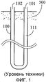
На фиг. 1 показан вариант осуществления обычного U-образного трубопровода (100), установленного внутри накопителя тепла (500);In FIG. 1 shows an embodiment of a conventional U-shaped conduit (100) installed inside a heat accumulator (500);
на фиг. 2 показан вариант осуществления обычного U-образного трубопровода (100), установленного внутри столбчатого теплопроводного тела (300), причем столбчатое теплопроводное тело (300) расположено внутри накопителя тепла (500);in FIG. 2 shows an embodiment of a conventional U-shaped conduit (100) installed inside a columnar heat-conducting body (300), wherein the columnar heat-conducting body (300) is located inside a heat accumulator (500);
на фиг. 3 показан структурный схематичный вид, иллюстрирующий, что две или больше радиально размещенные U-образные секции труб установлены внутри теплопроводного цилиндра, и теплоизолирующая структура установлена здесь рядом с периферией группы труб с одинаковым направлением потока, которые сосредоточены в направлении аксиального сердечника, согласно настоящему изобретению;in FIG. 3 is a structural schematic view illustrating that two or more radially arranged U-shaped pipe sections are installed inside a heat-conducting cylinder, and a heat insulating structure is installed here near the periphery of a group of pipes with the same flow direction, which are concentrated in the direction of the axial core according to the present invention;
на фиг. 4 показан вид в разрезе по фиг. 3;in FIG. 4 is a sectional view of FIG. 3;
на фиг. 5 показан структурный схематичный вид варианта осуществления, иллюстрирующий, что множество U-образных трубопроводов совместно соединено с первым концом (1101) для впуска и выпуска текучей среды общей трубы (200), представленной трубой большего диаметра, установленной в сердечнике столбчатого теплопроводного тела (300) согласно настоящему изобретению;in FIG. 5 is a structural schematic view of an embodiment illustrating that a plurality of U-shaped conduits are jointly connected to a first end (1101) for inlet and outlet of fluid of a common pipe (200) represented by a larger diameter pipe installed in a core of a columnar heat-conducting body (300) according to the present invention;
на фиг. 6 показан вид в разрезе изображения с фиг. 5;in FIG. 6 is a sectional view of the image of FIG. 5;
на фиг. 7 показан схематичный вид варианта осуществления, иллюстрирующий, что сегменты труб первого конца (101) для впуска и выпуска текучей среды и второго конца (102) для впуска и выпуска текучей среды в U-образном волнистом трубопроводе (600) волнообразно расположены в аксиальном направлении и возле края столбчатого теплопроводного тела (300) согласно настоящему изобретению;in FIG. 7 is a schematic view of an embodiment illustrating that pipe segments of a first end (101) for fluid inlet and outlet and a second end (102) for fluid inlet and outlet in a U-shaped wave conduit (600) are wave-like in the axial direction and near the edge of the columnar heat-conducting body (300) according to the present invention;
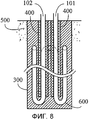
на фиг. 8 показан вид в разрезе изображения с фиг. 7;in FIG. 8 is a sectional view of the image of FIG. 7;
на фиг. 9 показан схематичный вид варианта осуществления, иллюстрирующий, что сегменты труб первого конца (101) для впуска и выпуска текучей среды в U-образном волнистом трубопроводе (600) расположены возле центра столбчатого теплопроводного тела (300), сегмент трубы между вторым концом для впуска и выпуска текучей среды (102) расположен возле периферии столбчатого теплопроводного тела (300) и U-образный волнистый трубопровод (600) между двумя сегментами труб волнисто размещается в аксиальном направлении и возле края столбчатого теплопроводного тела (300) согласно настоящему изобретению;in FIG. 9 is a schematic view of an embodiment illustrating that pipe segments of a first end (101) for fluid inlet and outlet in a U-shaped corrugated pipe (600) are located near the center of a columnar heat-conducting body (300), a pipe segment between a second end for inlet and the fluid outlet (102) is located near the periphery of the columnar heat-conducting body (300) and the U-shaped corrugated pipe (600) between the two pipe segments is wavy in the axial direction and near the edge of the columnar heat-conducting body (300) Concerning the present invention;
на фиг. 10 показан вид в разрезе по фиг. 9;in FIG. 10 is a sectional view of FIG. 9;
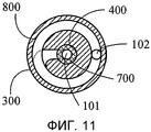
на фиг. 11 показан схематичный вид варианта осуществления, иллюстрирующий, что спиральный сегмент труб первого конца (101) для впуска и выпуска текучей среды и второго конца (102) для впуска и выпуска текучей среды в U-образном спиральном трубопроводе размещается по спирали в аксиальном направлении и возле края столбчатого теплопроводного тела (300) согласно настоящему изобретению; иin FIG. 11 is a schematic view of an embodiment illustrating that a spiral segment of pipes of a first end (101) for inlet and outlet of a fluid and a second end (102) for inlet and outlet of a fluid in a U-shaped spiral conduit are helical in the axial direction and near the edges of the columnar heat-conducting body (300) according to the present invention; and
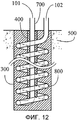
на фиг. 12 показан вид в разрезе по фиг. 11.in FIG. 12 is a sectional view of FIG. eleven.
Описание основных элементовDescription of the main elements
100: U-образный трубопровод100: U-shaped pipe
101: первый конец для впуска и выпуска текучей среды101: first end for fluid inlet and outlet
102: второй конец для впуска и выпуска текучей среды102: second end for fluid inlet and outlet
111: проводящая тепло текучая среда111: heat conductive fluid
200: общая труба200: common pipe
300: столбчатое теплопроводное тело300: columnar heat-conducting body
400: теплоизолирующее устройство400: heat insulating device
500: накопитель тепла500: heat storage
600: U-образный волнистый трубопровод600: U-shaped corrugated conduit
700: центральная труба U-образного спирального трубопровода700: central pipe of a U-shaped spiral pipe
800: U-образный спиральный трубопровод800: U-shaped coiled tubing
1101: первый конец для впуска и выпуска текучей среды1101: first end for fluid inlet and outlet
Подробное описание предпочтительных вариантов осуществления изобретенияDETAILED DESCRIPTION OF PREFERRED EMBODIMENTS
Настоящее изобретение относится к теплопроводному цилиндру, содержащему U-образный стержневой трубопровод и кольцевой трубопровод и предназначенному для установки в накопителе тепла (500), представленном естественным накопителем тепла, таким как грунт на небольшой глубине или пруд, озеро, река, океан и т.д., или искусственными объектами в твердом, или газообразном, или жидком состоянии; причем теплопроводный цилиндр, снабженный U-образным стержневым трубопроводом и кольцевым трубопроводом, выполнен таким образом, что сегменты труб на конце для впуска и/или конце для выпуска текучей среды U-образного стержневого трубопровода и кольцевого трубопровода непосредственно выполнены из теплоизолирующего материала, или же теплоизолирующая конструкция помещена между концом для впуска и концом для выпуска; таким образом, чтобы предотвратить потерю тепловой энергии из-за теплопроводности между соседними сегментами труб на конце для впуска и/или конце для выпуска с одной стороны при прохождении через них проводящей тепло текучей среды с перепадом температур.The present invention relates to a heat-conducting cylinder containing a U-shaped rod conduit and an annular conduit for installation in a heat accumulator (500) represented by a natural heat accumulator, such as a shallow depth of the ground or a pond, lake, river, ocean, etc. ., or by artificial objects in a solid, or gaseous, or liquid state; moreover, the heat-conducting cylinder provided with a U-shaped rod pipe and an annular pipe is made in such a way that the pipe segments at the inlet end and / or end for the fluid outlet of the U-shaped rod pipe and the annular pipe are directly made of heat-insulating material, or heat-insulating the structure is placed between the end for the inlet and the end for the outlet; so as to prevent the loss of thermal energy due to thermal conductivity between adjacent pipe segments at the inlet end and / or outlet end on the one hand when the heat-conducting fluid passes through them at a temperature differential.
Что касается теплопроводного цилиндра, содержащего U-образный стержневой трубопровод и кольцевой трубопровод, согласно настоящему изобретению, то каждый U-образный трубопровод (100) используется для пропуска через него одной или больше из следующих проводящих тепло текучих сред (111), включая пропуск:As for a heat-conducting cylinder containing a U-shaped rod pipe and an annular pipe according to the present invention, each U-shaped pipe (100) is used to pass through it one or more of the following heat-conducting fluids (111), including the pass:
1) текучую среду в жидком состоянии;1) fluid in a liquid state;
2) текучую среду в газообразном состоянии;2) a fluid in a gaseous state;
3) текучую среду, переходящую из жидкого в газообразное состояние; и3) a fluid passing from a liquid to a gaseous state; and
4) текучую среду, переходящую из газообразного в жидкое состояние.4) a fluid passing from a gaseous to a liquid state.
Обычно в U-образной трубопроводной системе или в U-образном трубопроводном теплообменнике часто происходит потеря тепловой энергии из-за теплопроводности за счет разности температур между концом для впуска текучей среды и концом для выпуска текучей среды, установленными на одной стороне, когда текучая среда с разностью температур проходит через них, как показано наследующих примерах.Typically, in a U-shaped pipe system or in a U-shaped pipe heat exchanger, thermal energy is often lost due to heat conduction due to a temperature difference between the fluid inlet end and the fluid outlet end mounted on one side when the fluid has a difference temperatures passes through them, as shown by the following examples.
На фиг. 1 показан вариант осуществления обычного U-образного трубопровода (100), установленного внутри накопителя тепла (500). Когда проводящая тепло текучая среда (111), проходящая через сегмент труб первого конца (101) для впуска и выпуска текучей среды и соседний сегмент труб второго конца (102) для впуска и выпуска текучей среды, соответственно установленный на той же стороне U-образного трубопровода (100), имеет разность температур, в двух сегментах трубопровода возникает теплопроводность, что ведет к потере тепловой энергии.In FIG. 1 shows an embodiment of a conventional U-shaped conduit (100) installed inside a heat accumulator (500). When the heat-conducting fluid (111) passing through the pipe segment of the first end (101) for fluid inlet and outlet and the adjacent pipe segment of the second end (102) for fluid inlet and outlet, respectively mounted on the same side of the U-shaped pipe (100), has a temperature difference, thermal conductivity occurs in two segments of the pipeline, which leads to the loss of thermal energy.
На фиг. 2 показан вариант осуществления обычного U-образного трубопровода (100), установленного в столбчатом теплопроводном теле (300), в котором столбчатое трубопроводное тело (300) расположено в накопителе тепла (500).In FIG. 2 shows an embodiment of a conventional U-shaped conduit (100) installed in a columnar heat-conducting body (300), in which a columnar conduit body (300) is located in a heat storage unit (500).
Когда столбчатое теплопроводное тело (300) установлено в теплопроводном цилиндре вместе с U-образным стержневым трубопроводом и кольцевым трубопроводом в накопителе тепла (500), представленном естественным накопителем тепла, таким как грунт на небольшой глубине или пруд, озеро, река, океан и т.д., или искусственными объектами в твердом, или газообразном, или жидком состоянии, и проводящая тепло текучая среда (111) с разностью температур проходит через первый конец (101) для впуска и выпуска текучей среды и второй конец (102) для впуска и выпуска текучей среды U-образного трубопровода, будет наблюдаться потеря тепловой энергии из-за теплопроводности между соседними сегментами труб первого конца (101) для впуска и выпуска текучей среды и второго конца (102) для впуска и выпуска текучей среды, установленными на одной стороне.When a columnar heat-conducting body (300) is installed in a heat-conducting cylinder together with a U-shaped rod conduit and an annular conduit in a heat accumulator (500), represented by a natural heat accumulator, such as soil at a shallow depth or a pond, lake, river, ocean, etc. etc., or by artificial objects in a solid, or gaseous, or liquid state, and a heat-conducting fluid (111) with a temperature difference passes through the first end (101) for the inlet and outlet of the fluid and the second end (102) for the inlet and outlet fluid medium of a U-shaped pipeline, there will be a loss of thermal energy due to heat conduction between adjacent pipe segments of the first end (101) for the inlet and outlet of the fluid and the second end (102) for the inlet and outlet of the fluid installed on one side.
Настоящее изобретение относится к теплопроводному цилиндру, содержащему U-образный стержневой трубопровод и кольцевой трубопровод и предназначенному для установки в накопителе тепла (500), представленном естественным накопителем тепла, таким как грунт на небольшой глубине или пруд, озеро, река, океан и т.д., или искусственными объектами в твердом, или газообразном, или жидком состоянии; причем теплопроводный цилиндр, снабженный U-образным стержневым трубопроводом и кольцевым трубопроводом, выполнен таким образом, что U-образные сегменты труб на конце для впуска и/или конце для выпуска текучей среды, которые являются радиальными U-образными трубопроводами, предназначенными для пропуска тепловой энергии через друг друга, непосредственно выполнены из теплоизолирующего материала, или же теплоизолирующая конструкция помещена между концом для впуска и концом для выпуска; таким образом, чтобы предотвратить потерю тепловой энергии из-за теплопроводности между соседними сегментами труб на конце для впуска и/или конце для выпуска с одной стороны при прохождении через них проводящей тепло текучей среды с перепадом температур.The present invention relates to a heat-conducting cylinder containing a U-shaped rod conduit and an annular conduit for installation in a heat accumulator (500) represented by a natural heat accumulator, such as a shallow depth of the ground or a pond, lake, river, ocean, etc. ., or by artificial objects in a solid, or gaseous, or liquid state; moreover, the heat-conducting cylinder, equipped with a U-shaped rod pipe and an annular pipe, is made in such a way that the U-shaped pipe segments at the inlet end and / or end for the release of fluid, which are radial U-shaped pipelines designed to transmit thermal energy through each other, directly made of heat insulating material, or the heat insulating structure is placed between the end for inlet and the end for exhaust; so as to prevent the loss of thermal energy due to thermal conductivity between adjacent pipe segments at the inlet end and / or outlet end on the one hand when the heat-conducting fluid passes through them at a temperature differential.
На фиг. 3 показан структурный схематичный вид, иллюстрирующий, что две или больше радиально размещенные U-образные секции труб установлены внутри теплопроводного цилиндра, и теплоизолирующая структура установлена здесь рядом с периферией группы труб с одинаковым направлением потока, которые сосредоточены в направлении аксиального сердечника, согласно настоящему изобретению.In FIG. 3 is a structural schematic view illustrating that two or more radially arranged U-shaped pipe sections are installed inside a heat-conducting cylinder, and a heat-insulating structure is installed here near the periphery of a group of pipes with the same flow direction, which are concentrated in the direction of the axial core according to the present invention.
На фиг. 4 показан вид в разрезе по фиг. 3.In FIG. 4 is a sectional view of FIG. 3.
Как показано на фиг. 3 и фиг. 4, основными компонентами являются следующие:As shown in FIG. 3 and FIG. 4, the main components are as follows:
- U-образный трубопровод (100): выполнен из U-образного трубчатого тела для проводящей тепло текучей среды (111), проходящей по нему, где U-образный трубопровод (100) используется для установки внутри столбчатого теплопроводного тела (300), образуемого твердым или коллоидным объектом; каждый U-образный трубопровод (100) имеет первый конец (101) для впуска и выпуска текучей среды и второй конец (102) для впуска и выпуска текучей среды, причем сегменты труб возле первого конца (101) для впуска и выпуска текучей среды сосредоточены и установлены рядом с сердечником столбчатого теплопроводного тела (300), а сегменты труб возле второго конца (102) для впуска и выпуска текучей среды радиально размещаются в аксиальном направлении и возле края столбчатого теплопроводного тела (300);- U-shaped conduit (100): made of a U-shaped tubular body for heat-conducting fluid (111) passing through it, where the U-shaped conduit (100) is used for installation inside a columnar heat-conducting body (300) formed by a solid or colloidal object; each U-shaped conduit (100) has a first end (101) for fluid inlet and outlet and a second end (102) for fluid inlet and outlet, with pipe segments near the first end (101) for fluid inlet and outlet mounted next to the core of the columnar heat-conducting body (300), and pipe segments near the second end (102) for fluid inlet and outlet are radially arranged in the axial direction and near the edge of the columnar heat-conducting body (300);
- столбчатое теплопроводное тело (300): выполнено из теплопроводного материала, причем столбчатое теплопроводное тело (300) имеет столбчатую структуру с поперечным сечением различной геометрической формы, таким как круглое, овальное, квадратное, прямоугольное или звездообразное, покрывающую U-образный трубопровод (100) и теплоизолирующее устройство (400); и- columnar heat-conducting body (300): made of heat-conducting material, and the columnar heat-conducting body (300) has a columnar structure with a cross-section of various geometric shapes, such as round, oval, square, rectangular or star-shaped, covering a U-shaped pipe (100) and a heat insulating device (400); and
- теплоизолирующее устройство (400): относящееся к теплоизолирующей структуре, образуется следующими элементами с теплоизолирующими свойствами, такими как твердое, гибкое тело, или пена, или окутывающий коллоид, газ, или жидкость, или вакуумная структура, которые должны быть расположены между сегментами труб возле первого конца (101) для впуска и выпуска текучей среды каждого из U-образных трубопроводов (100), которые сосредоточены и установлены рядом с аксиальным сердечником столбчатого трубопроводного тела (300), и между сегментами труб возле второго конца (102) для впуска и выпуска текучей среды каждого из U-образных трубопроводов, или которые должны быть заменены сегментами труб возле первого конца (101) для впуска и выпуска текучей среды, непосредственно выполненными из теплоизолирующего материала или обернутыми теплоизолирующим материалом; с помощью указанной теплоизолирующей структуры обеспечивается значительное уменьшение потерь тепловой энергии, вызванных теплопроводностью между прилегающими сегментами труб первого конца (101) для впуска и выпуска текучей среды и второго конца (102) для впуска и выпуска текучей среды на той же стороне U-образного трубопровода (100).- heat insulating device (400): related to the heat insulating structure, is formed by the following elements with heat insulating properties, such as a solid, flexible body, or foam, or enveloping colloid, gas, or liquid, or vacuum structure, which should be located between the pipe segments near the first end (101) for the inlet and outlet of the fluid of each of the U-shaped pipelines (100), which are concentrated and installed next to the axial core of the columnar pipe body (300), and between the pipe segments near the other end (102) for the inlet and outlet of the fluid of each of the U-shaped pipelines, or which must be replaced by pipe segments near the first end (101) for the inlet and outlet of the fluid, directly made of heat insulating material or wrapped in heat insulating material; Using this heat-insulating structure, a significant reduction in thermal energy losses caused by thermal conductivity between adjacent segments of the pipes of the first end (101) for the inlet and outlet of the fluid and the second end (102) for the inlet and outlet of the fluid on the same side of the U-shaped pipe ( one hundred).
Что касается теплопроводного цилиндра, содержащего U-образный стержневой трубопровод и кольцевой трубопровод согласно настоящему изобретению, то он также может иметь множество комплектов U-образных труб, вместе соединенных с первым концом (1101) для впуска и выпуска текучей среды общей трубы (200), образуемой трубой большего диаметра, установленной в аксиальном сердечнике столбчатого теплопроводного тела (300), и может быть снабжен вторым концом (102) для впуска и выпуска текучей среды, радиально размещенным в аксиальном направлении относительно столбчатого теплопроводного тела (300).As for the heat-conducting cylinder containing the U-shaped core pipe and the annular pipe according to the present invention, it can also have many sets of U-shaped pipes, together connected to the first end (1101) for the inlet and outlet of the fluid of the common pipe (200), formed by a pipe of a larger diameter installed in the axial core of the columnar heat-conducting body (300), and can be provided with a second end (102) for the inlet and outlet of the fluid radially placed in the axial direction relative to o columnar heat-conducting body (300).
На фиг. 5 показан структурный схематичный вид варианта осуществления, иллюстрирующий, что множество U-образных трубопроводов совместно соединяется с первым концом (1101) для впуска и выпуска текучей среды общей трубы (200), представленной трубой большего диаметра, установленной в сердечнике столбчатого теплопроводного тела (300) согласно настоящему изобретению.In FIG. 5 is a structural schematic view of an embodiment illustrating that a plurality of U-shaped conduits are jointly connected to a first end (1101) for inlet and outlet of fluid of a common pipe (200) represented by a larger diameter pipe installed in a core of a columnar heat-conducting body (300) according to the present invention.
На фиг. 6 показан вид в разрезе по фиг. 5.In FIG. 6 is a sectional view of FIG. 5.
Как показано на фиг. 5 и фиг. 6, система представлена главным образом по меньшей мере двумя U-образными трубопроводами (100) для проводящей тепло текучей среды (111), проходящей по ним, причем каждый из U-образных трубопроводов (100) используется для установки в столбчатом теплопроводном теле (300), состоящем из твердого или коллоидного объекта; каждый из U-образных трубопроводов (100) совместно соединен с первым концом (1101) для впуска и выпуска текучей среды общей трубы (200), представленной трубой большего диаметра, установленной в сердечнике столбчатого теплопроводного тела (300), и установлен со вторым концом (102) для впуска и выпуска текучей среды и сегментами труб, радиально расположенным в аксиальном направлении относительно столбчатого теплопроводного тела (300); первый конец (1101) для впуска и выпуска текучей среды общей трубы (200) расположен в аксиальном сердечнике столбчатого теплопроводного тела (300) и также установлен с теплоизолирующим устройством (400) между сегментами труб возле второго конца для впуска и выпуска текучей среды (102) каждого U-образного трубопровода (100) и сегменты труб возле второго конца для впуска и выпуска текучей среды (102) каждого U-образного трубопровода (100) радиально расположены в аксиальном направлении и возле края столбчатого теплопроводного тела (300); иAs shown in FIG. 5 and FIG. 6, the system is represented mainly by at least two U-shaped pipelines (100) for heat-conducting fluid (111) passing through them, each of the U-shaped pipelines (100) being used for installation in a columnar heat-conducting body (300) consisting of a solid or colloidal object; each of the U-shaped pipelines (100) is jointly connected to the first end (1101) for the inlet and outlet of the fluid of the common pipe (200), represented by a larger diameter pipe installed in the core of the columnar heat-conducting body (300), and installed with the second end ( 102) for the inlet and outlet of the fluid and pipe segments radially located in the axial direction relative to the columnar heat-conducting body (300); the first end (1101) for the inlet and outlet of fluid of the common pipe (200) is located in the axial core of the columnar heat-conducting body (300) and is also installed with a heat-insulating device (400) between the pipe segments near the second end for inlet and outlet of the fluid (102) each U-shaped pipe (100) and pipe segments near the second end for fluid inlet and outlet (102) of each U-shaped pipe (100) are radially located in the axial direction and near the edge of the columnar heat-conducting body (300); and
- столбчатое теплопроводное тело (300): выполнено из теплопроводного материала, в котором столбчатое теплопроводное тело (300) имеет столбчатую структуру с поперечным сечением различной геометрической формы, таким как круглое, овальное, квадратное, прямоугольное или звездообразное, покрывающую U-образный трубопровод (100) и теплоизолирующее устройство (400); и- columnar heat-conducting body (300): made of a heat-conducting material in which the columnar heat-conducting body (300) has a columnar structure with a cross-section of various geometric shapes, such as a round, oval, square, rectangular or star-shaped, covering a U-shaped pipe (100) ) and a heat insulating device (400); and
- теплоизолирующее устройство (400): относящееся к теплоизолирующей структуре, образуется следующими элементами с теплоизолирующими свойствами, такими как твердое, гибкое тело, или пена, или окутывающий коллоид, газ, или жидкость, или вакуумная структура, которые должны быть помещены между сегментами труб возле второго конца (102) для впуска и выпуска текучей среды U-образного трубопровода (100) и сегментами труб возле первого конца (1101) для впуска и выпуска текучей среды общей трубы (200), или заменяется сегментами труб возле первого конца (101) для впуска и выпуска текучей среды, непосредственно выполненными из теплоизолирующего материала или обернутыми теплоизолирующим материалом; при этом с помощью указанной структуры обеспечивается уменьшение потерь тепловой энергии, вызванных теплопроводностью между сегментами труб первого конца (1101) для впуска и выпуска текучей среды с общей трубой (200) и вторым концом (102) для впуска и выпуска текучей среды.- heat insulating device (400): related to the heat insulating structure, is formed by the following elements with heat insulating properties, such as a solid, flexible body, or foam, or enveloping colloid, gas, or liquid, or vacuum structure, which must be placed between the pipe segments near the second end (102) for fluid inlet and outlet of the U-shaped pipe (100) and pipe segments near the first end (1101) for fluid inlet and outlet of the common pipe (200), or replaced by pipe segments near the first end (101) for at start-up and release of fluid directly made of heat insulating material or wrapped in heat insulating material; however, using this structure, a reduction in thermal energy losses caused by thermal conductivity between the pipe segments of the first end (1101) for the inlet and outlet of the fluid with the common pipe (200) and the second end (102) for the inlet and outlet of the fluid is reduced.
На фиг. 7 показан схематичный вид варианта осуществления, иллюстрирующий, что сегменты труб первого конца (101) для впуска и выпуска текучей среды и второго конца (102) для впуска и выпуска текучей среды в U-образном волнистом трубопроводе (600) волнообразно размещается в аксиальном направлении и возле края столбчатого теплопроводного тела (300) согласно настоящему изобретению.In FIG. 7 is a schematic view of an embodiment illustrating that pipe segments of a first end (101) for fluid inlet and outlet and a second end (102) for fluid inlet and outlet in a U-shaped wave conduit (600) are wave-like in the axial direction and near the edge of the columnar heat-conducting body (300) according to the present invention.
На фиг. 8 показан вид в разрезе по фиг. 7.In FIG. 8 is a sectional view of FIG. 7.
Как показано на фиг. 7 и фиг. 8, основными компонентами являются следующие:As shown in FIG. 7 and FIG. 8, the main components are as follows:
- U-образный волнистый трубопровод (600): выполнен из U-образного волнистого трубчатого тела для проводящей тепло текучей среды (111), проходящей по нему, причем U-образный волнистый трубопровод (600) используется для установки в столбчатом теплопроводном теле (300), состоящем из твердого или коллоидного объекта; при этом U-образный волнистый трубопровод (600) волнообразно расположен вокруг в аксиальном направлении и возле края столбчатого теплопроводного тела (300) с верхним и нижним волнистым изгибом, и оба конца U-образного волнистого трубопровода (600) имеют первый конец (101) для впуска и выпуска текучей среды и второй конец (102) для впуска и выпуска текучей среды, связанные между собой;- U-shaped corrugated conduit (600): made of a U-shaped corrugated tubular body for conductive heat fluid (111) passing through it, and the U-shaped corrugated conduit (600) is used for installation in a columnar heat-conducting body (300) consisting of a solid or colloidal object; wherein the U-shaped undulating conduit (600) is undulating around around the axial direction and near the edge of the columnar heat-conducting body (300) with the upper and lower undulating bend, and both ends of the U-shaped undulating conduit (600) have a first end (101) for fluid inlet and outlet; and a second end (102) for fluid inlet and outlet, interconnected;
- столбчатое теплопроводное тело (300): выполнено из теплопроводного материала, причем столбчатое теплопроводное тело (300) имеет столбчатую структуру с поперечным сечением различной геометрической формы, таким как круглое, овальное, квадратное, прямоугольное или звездообразное, покрывающую U-образный волнистый трубопровод (600) и теплоизолирующее устройство (400); и- columnar heat-conducting body (300): made of heat-conducting material, and the columnar heat-conducting body (300) has a columnar structure with a cross section of various geometric shapes, such as round, oval, square, rectangular or star-shaped, covering a U-shaped corrugated pipeline (600 ) and a heat insulating device (400); and
- теплоизолирующее устройство (400): относящееся к теплоизолирующей структуре, образуется следующими элементами с теплоизолирующими свойствами, такими как твердое, гибкое тело, или пена, или окутывающий коллоид, газ, или жидкость, или вакуумная структура, которые должны быть помещены между сегментами труб возле первого конца (101) для впуска и выпуска текучей среды U-образного волнистого трубопровода (600), которые сосредоточены и установлены рядом с аксиальным сердечником столбчатого трубопроводного тела (300), и между сегментами труб возле второго конца (102) для впуска и выпуска текучей среды U-образного волнистого трубопровода (600), или которые должны быть заменены сегментами труб возле первого конца (101) для впуска и выпуска текучей среды, непосредственно выполненными из теплоизолирующего материала или обернутыми теплоизолирующим материалом; с помощью указанной теплоизолирующей структуры обеспечивается значительное уменьшение потерь тепловой энергии, вызванных теплопроводностью между прилегающими сегментами труб первого конца (101) для впуска и выпуска текучей среды и второго конца (102) для впуска и выпуска текучей среды на той же стороне U-образного волнистого трубопровода (600).- heat insulating device (400): related to the heat insulating structure, is formed by the following elements with heat insulating properties, such as a solid, flexible body, or foam, or enveloping colloid, gas, or liquid, or vacuum structure, which must be placed between the pipe segments near the first end (101) for the inlet and outlet of the fluid of the U-shaped corrugated pipe (600), which are concentrated and installed near the axial core of the columnar pipe body (300), and between the pipe segments near the second th end (102) for the inlet and outlet fluid U-shaped wavy piping (600), or which should be replaced tube segments near the first end (101) for the inlet and outlet fluid directly made of thermal insulating material, or wrapped with a heat insulating material; Using this heat-insulating structure, a significant reduction in thermal energy losses caused by heat conduction between adjacent segments of the pipes of the first end (101) for the inlet and outlet of the fluid and the second end (102) for the inlet and outlet of the fluid on the same side of the U-shaped corrugated pipe (600).
На фиг. 9 показан схематичный вид варианта осуществления, иллюстрирующий, что сегменты труб первого конца (101) для впуска и выпуска текучей среды в U-образном волнистом трубопроводе (600) помещаются возле центра столбчатого теплопроводного тела (300), сегмент трубы между вторым концом (102) для впуска и выпуска текучей среды расположен возле периферии столбчатого теплопроводного тела (300), и U-образный волнистый трубопровод (600) между двумя сегментами труб волнообразно расположен в аксиальном направлении и возле края столбчатого теплопроводного тела (300) согласно настоящему изобретению.In FIG. 9 is a schematic view of an embodiment illustrating that pipe segments of a first end (101) for fluid inlet and outlet in a U-shaped corrugated pipe (600) are placed near the center of a columnar heat-conducting body (300), a pipe segment between a second end (102) for the inlet and outlet of the fluid is located near the periphery of the columnar heat-conducting body (300), and the U-shaped corrugated pipe (600) between the two pipe segments is undulating in the axial direction and near the edge of the columnar heat-conducting body (300) ccording to the present invention.
На фиг. 10 показан вид в разрезе по фиг. 9.In FIG. 10 is a sectional view of FIG. 9.
Как показано на фиг. 9 и фиг. 10, основными компонентами являются следующие:As shown in FIG. 9 and FIG. 10, the main components are as follows:
- U-образный волнистый трубопровод (600): выполнен из U-образного волнистого трубчатого тела для проводящей тепло текучей среды (111), проходящей по нему, причем U-образный волнистый трубопровод (600) используется для установки в столбчатом теплопроводном теле (300), состоящем из твердого или коллоидного объекта; отличием является то, что U-образный волнистый трубопровод (600) волнообразно расположен вокруг в аксиальном направлении и возле края столбчатого теплопроводного тела (300) с верхним и нижним волнистым изгибом, и оба конца U-образного волнистого трубопровода (600) имеют первый конец для впуска и выпуска текучей среды (101) и второй конец для впуска и выпуска текучей среды (102), связанные между собой, при этом сегмент труб первого конца для впуска и выпуска текучей среды (101) расположен возле центра столбчатого теплопроводного тела (300), а сегмент труб между вторым концом для впуска и выпуска текучей среды (102) расположен возле периферии столбчатого теплопроводного тела (300), и U-образный волнистый трубопровод (600) между двумя сегментами труб волнообразно расположен в аксиальном направлении и возле края столбчатого теплопроводного тела (300);- U-shaped corrugated conduit (600): made of a U-shaped corrugated tubular body for conductive heat fluid (111) passing through it, and the U-shaped corrugated conduit (600) is used for installation in a columnar heat-conducting body (300) consisting of a solid or colloidal object; the difference is that the U-shaped undulating conduit (600) is undulating around in the axial direction and near the edge of the columnar heat-conducting body (300) with an upper and lower undulating bend, and both ends of the U-shaped undulating conduit (600) have a first end for fluid inlet and outlet (101) and a second end for fluid inlet and outlet (102), interconnected, while the pipe segment of the first end for fluid inlet and outlet (101) is located near the center of the columnar heat-conducting body (300), and pipe segment m Between the second end for fluid inlet and outlet (102) is located near the periphery of the columnar heat-conducting body (300), and the U-shaped corrugated pipe (600) between the two pipe segments is wave-like in the axial direction and near the edge of the columnar heat-conducting body (300);
- столбчатое теплопроводное тело (300): выполнено из теплопроводного материала, причем столбчатое теплопроводное тело (300) имеет столбчатую структуру с поперечным сечением различной геометрической формы, таким как круглое, овальное, квадратное, прямоугольное или звездообразное, покрывающую U-образный волнистый трубопровод (600) и теплоизолирующее устройство (400); и- columnar heat-conducting body (300): made of heat-conducting material, and the columnar heat-conducting body (300) has a columnar structure with a cross section of various geometric shapes, such as round, oval, square, rectangular or star-shaped, covering a U-shaped corrugated pipeline (600 ) and a heat insulating device (400); and
- теплоизолирующее устройство (400): относящееся к теплоизолирующей структуре, образуется следующими элементами с теплоизолирующими свойствами, такими как твердое, гибкое тело, или пена, или окутывающий коллоид, газ, или жидкость, или вакуумная структура, которые должны быть расположены между сегментами труб возле первого конца (101) для впуска и выпуска текучей среды U-образного волнистого трубопровода (600), которые сосредоточены и установлены рядом с аксиальным сердечником столбчатого трубопроводного тела (300), и между сегментами труб возле второго конца (102) для впуска и выпуска текучей среды U-образного волнистого трубопровода (600), или которые должны быть заменены сегментами труб возле первого конца (101) для впуска и выпуска текучей среды, непосредственно выполненными из теплоизолирующего материала или обернутыми теплоизолирующим материалом; при этом с помощью указанной теплоизолирующей структуры обеспечивается значительное уменьшение потерь тепловой энергии, вызванных теплопроводностью между прилегающими сегментами труб первого конца (101) для впуска и выпуска текучей среды и второго конца (102) для впуска и выпуска текучей среды на той же стороне U-образного волнистого трубопровода (600).- heat insulating device (400): related to the heat insulating structure, is formed by the following elements with heat insulating properties, such as a solid, flexible body, or foam, or enveloping colloid, gas, or liquid, or vacuum structure, which should be located between the pipe segments near the first end (101) for the inlet and outlet of the fluid of the U-shaped corrugated pipe (600), which are concentrated and installed next to the axial core of the columnar pipe body (300), and between the pipe segments near torogo end (102) for the inlet and outlet fluid U-shaped wavy piping (600), or which should be replaced tube segments near the first end (101) for the inlet and outlet fluid directly made of thermal insulating material, or wrapped with a heat insulating material; while using the specified insulating structure provides a significant reduction in heat loss due to thermal conductivity between adjacent segments of the pipes of the first end (101) for the inlet and outlet of the fluid and the second end (102) for the inlet and outlet of the fluid on the same side of the U-shaped corrugated pipeline (600).
На фиг. 11 показан схематичный вид варианта осуществления, иллюстрирующий, что спиральный сегмент труб первого конца для впуска и выпуска текучей среды (101) и второго конца для впуска и выпуска текучей среды (102) в U-образном спиральном трубопроводе размещается по спирали в аксиальном направлении и возле края столбчатого теплопроводного тела (300) согласно настоящему изобретению.In FIG. 11 is a schematic view of an embodiment illustrating that a spiral segment of pipes of a first end for inlet and outlet of a fluid (101) and a second end for inlet and outlet of a fluid (102) in a U-shaped spiral conduit are helical in the axial direction and near the edges of the columnar heat-conducting body (300) according to the present invention.
На фиг. 12 показана вид в разрезе по фиг. 11.In FIG. 12 is a sectional view of FIG. eleven.
Как показано на фиг. 11 и фиг. 12, основными компонентами являются следующие:As shown in FIG. 11 and FIG. 12, the main components are as follows:
- U-образный спиральный трубопровод (800): выполнен из U-образного спирального трубчатого тела для проводящей тепло текучей среды (111), проходящей по нему, причем U-образный спиральный трубопровод (800) используется для установки в столбчатом теплопроводном теле (300), состоящем из твердого или коллоидного объекта; при этом U-образный спиральный трубопровод (800) расположен по спирали вокруг в аксиальном направлении и возле края столбчатого теплопроводного тела (300), и оба конца U-образного спирального трубопровода (800) имеют первый конец (101) для впуска и выпуска текучей среды и второй конец (102) для впуска и выпуска текучей среды, связанные между собой, причем первый конец (101) для впуска и выпуска текучей среды, который расположен на верхнем конце в центре спиральной структуры, непосредственно проходит к нижней части U-образного спирального трубопровода (800) через центральную трубу U-образного спирального трубопровода (700), а второй конец (102) для впуска и выпуска текучей среды расположен на верхнем конце U-образного спирального трубопровода (800) вверх по спирали на своем участке;- U-shaped spiral pipe (800): made of a U-shaped spiral tubular body for conductive heat fluid (111) passing through it, and the U-shaped spiral pipe (800) is used for installation in a columnar heat-conducting body (300) consisting of a solid or colloidal object; wherein the U-shaped spiral pipe (800) is helically arranged around in the axial direction and near the edge of the columnar heat-conducting body (300), and both ends of the U-shaped spiral pipe (800) have a first end (101) for fluid inlet and outlet and a second end (102) for fluid inlet and outlet, interconnected, the first end (101) for fluid inlet and outlet, which is located at the upper end in the center of the spiral structure, directly passes to the lower part of the U-shaped spiral pipeline (800 ) through the central pipe of the U-shaped spiral pipe (700), and the second end (102) for fluid inlet and outlet is located on the upper end of the U-shaped spiral pipe (800) upward spiral in its area;
- столбчатое теплопроводное тело (300): выполнено из теплопроводного материала, при этом столбчатое теплопроводное тело (300) имеет столбчатую структуру с поперечным сечением различной геометрической формы, таким как круглое, овальное, квадратное, прямоугольное или звездообразное, покрывающую U-образный спиральный трубопровод (800) и теплоизолирующее устройство (400); и- columnar heat-conducting body (300): made of heat-conducting material, while the columnar heat-conducting body (300) has a columnar structure with a cross section of various geometric shapes, such as a round, oval, square, rectangular or star-shaped, covering a U-shaped spiral pipeline ( 800) and a heat insulating device (400); and
- теплоизолирующее устройство (400): относящееся к теплоизолирующей структуре, образуется следующими элементами с теплоизолирующими свойствами, такими как твердое, гибкое тело, или пена, или окутывающий коллоид, газ, или жидкость, или вакуумная структура, при этом сегмент центральной трубы U-образной спиральной трубы (700) U-образного спирального трубопровода (800), который расположен в аксиальном сердечнике столбчатого трубопроводного тела (300) и проходит вверх к первому концу (101) для впуска и выпуска текучей среды, непосредственно выполнен из теплоизолирующего материала или обернут теплоизолирующим материалом, или теплоизолирующее устройство (400) расположено между U-образным спиральным трубопроводом (800) вокруг и рядом с краем столбчатого теплопроводного тела (300), вверх по спирали на своем участке, проходящем ко второму концу (102) для впуска и выпуска текучей среды, и сегментом центральной трубы U-образной спиральной трубы (700); при этом с помощью указанного теплоизолирующего устройства (400) обеспечивается значительное уменьшение потерь тепловой энергии, вызванных теплопроводностью между центральной трубой U-образной спиральной трубы (700), установленной в центре нижней части того же U-образного спирального трубопровода (800), ведущей вверх к первому концу для впуска и выпуска текучей среды (101), и U-образным спиральным трубопроводом (800), проходящим ко второму концу (102) для впуска и выпуска текучей среды.- heat-insulating device (400): related to the heat-insulating structure, is formed by the following elements with heat-insulating properties, such as a solid, flexible body, or foam, or enveloping a colloid, gas, or liquid, or vacuum structure, while the central tube segment is U-shaped spiral pipe (700) of the U-shaped spiral pipe (800), which is located in the axial core of the columnar pipe body (300) and extends up to the first end (101) for the inlet and outlet of the fluid, is directly made of t The heat-insulating material is either wrapped in heat-insulating material, or the heat-insulating device (400) is located between the U-shaped spiral pipe (800) around and near the edge of the columnar heat-conducting body (300), upward spiral in its section, passing to the second end (102) for fluid inlet and outlet, and a central pipe segment of a U-shaped spiral pipe (700); while using the specified heat-insulating device (400) provides a significant reduction in heat loss caused by thermal conductivity between the Central pipe of the U-shaped spiral pipe (700) installed in the center of the lower part of the same U-shaped spiral pipe (800) leading up to a first end for fluid inlet and outlet (101), and a U-shaped spiral conduit (800) extending to a second end (102) for fluid inlet and outlet.
Claims (3)
причем теплопроводный цилиндр снабжен множеством U-образных трубопроводов (100) и выполнен так, что теплоизоляция (400) находится между концом для впуска текучей среды и концом для выпуска текучей среды каждого из множества U-образных трубопроводов (100), таким образом, чтобы предотвратить потерю тепловой энергии из-за теплопроводности между соседними сегментами трубопровода на конце для впуска и конце для выпуска на той же стороне при прохождении через них проводящей тепло текучей среды с перепадом температур;
при этом каждый из множества U-образных трубопроводов (100) используется для пропуска через них одной или более из следующих проводящих тепло текучих сред (111), включая:
1) текучую среду в жидком состоянии;
2) текучую среду в газообразном состоянии;
3) текучую среду, переходящую из жидкого в газообразное состояние; и
4) текучую среду, переходящую из газообразного в жидкое состояние,
причем две или более радиально размещенные секции U-образного трубопровода установлены внутри теплопроводного цилиндра, при этом две или более радиально размещенные секции U-образного трубопровода отделены друг от друга и имеют внутренние проходы, которые не сообщаются друг с другом внутри теплопроводного цилиндра;
причем основными компонентами теплопроводного цилиндра являются следующие:
множество U-образных трубопроводов (100): каждый выполнен из U-образного трубчатого тела для проводящей тепло текучей среды (111), проходящей по нему, при этом множество U-образных трубопроводов (100) установлено внутри столбчатого теплопроводного тела (300), образованного твердым или коллоидным объектом; каждый U-образный трубопровод (100) имеет отдельный первый конец (101) для впуска и выпуска текучей среды и отдельный второй конец (102) для впуска и выпуска текучей среды, причем сегменты трубопровода возле первого конца (101) для впуска и выпуска текучей среды установлены рядом с аксиальным сердечником столбчатого теплопроводного тела (300), а сегменты трубопровода возле второго конца (102) для впуска и выпуска текучей среды радиально размещены в аксиальном направлении и возле края столбчатого теплопроводного тела (300);
столбчатое теплопроводное тело (300): выполнено из теплопроводного материала, причем столбчатое теплопроводное тело (300) имеет столбчатую структуру с поперечным сечением различной геометрической формы, покрывающей U-образный трубопровод (100) и теплоизолирующее устройство (400); и
теплоизолирующее устройство (400): образовано из теплоизолирующей структуры с теплоизолирующими свойствами, причем теплоизолирующая структура включает одно из твердого тела, гибкого тела, пены, и окутывающего коллоида, газа, жидкости, или вакуумной структуры, которые должны быть помещены между сегментами трубопровода возле первого конца (101) для впуска и выпуска текучей среды каждого из U-образных трубопроводов (100), которые установлены рядом с аксиальным сердечником столбчатого трубопроводного тела (300), и сегментами трубопровода возле второго конца (102) для впуска и выпуска текучей среды каждого из U-образных трубопроводов для значительного уменьшения потерь тепловой энергии, вызванных теплопроводностью между соседними сегментами трубопровода первого конца (101) для впуска и выпуска текучей среды и второго конца (102) для впуска и выпуска текучей среды на той же стороне U-образного трубопровода (100).1. A heat-conducting cylinder designed for installation in a heat accumulator (500), represented by a natural heat accumulator, including one of the soil at a shallow depth, a reservoir, and artificial objects in a solid, gaseous, or liquid state;
moreover, the heat-conducting cylinder is provided with a plurality of U-shaped pipelines (100) and is configured so that the thermal insulation (400) is between the end for fluid inlet and the end for fluid outlet of each of the plurality of U-shaped pipelines (100), so as to loss of thermal energy due to thermal conductivity between adjacent segments of the pipeline at the end for inlet and end for release on the same side when heat-conducting fluid passes through them with a temperature difference;
each of the plurality of U-shaped pipelines (100) is used to pass through them one or more of the following heat-conducting fluids (111), including:
1) fluid in a liquid state;
2) a fluid in a gaseous state;
3) a fluid passing from a liquid to a gaseous state; and
4) a fluid passing from a gaseous to a liquid state,
moreover, two or more radially placed sections of the U-shaped pipe are installed inside the heat-conducting cylinder, while two or more radially placed sections of the U-shaped pipe are separated from each other and have internal passages that do not communicate with each other inside the heat-conducting cylinder;
the main components of the heat-conducting cylinder are the following:
a plurality of U-shaped pipelines (100): each is made of a U-shaped tubular body for heat-conducting fluid (111) passing through it, while a plurality of U-shaped pipelines (100) are installed inside the columnar heat-conducting body (300) formed solid or colloidal object; each U-shaped conduit (100) has a separate first end (101) for fluid inlet and outlet and a separate second end (102) for fluid inlet and outlet, with pipe segments near the first end (101) for fluid inlet mounted next to the axial core of the columnar heat-conducting body (300), and the pipe segments near the second end (102) for the inlet and outlet of the fluid are radially placed in the axial direction and near the edge of the columnar heat-conducting body (300);
columnar heat-conducting body (300): made of heat-conducting material, and the columnar heat-conducting body (300) has a columnar structure with a cross section of various geometric shapes, covering a U-shaped pipe (100) and a heat insulating device (400); and
heat insulating device (400): formed from a heat insulating structure with heat insulating properties, the heat insulating structure comprising one of a solid, flexible body, foam, and an enveloping colloid, gas, liquid, or vacuum structure, which must be placed between the segments of the pipeline near the first end (101) for the inlet and outlet of the fluid of each of the U-shaped pipelines (100), which are installed next to the axial core of the columnar pipe body (300), and pipe segments near the the end of the pipe (102) for the inlet and outlet of the fluid of each of the U-shaped pipelines to significantly reduce thermal energy losses caused by heat conduction between adjacent pipe segments of the first end (101) for the inlet and outlet of the fluid and the second end (102) for the inlet and fluid outlet on the same side of the U-shaped pipe (100).
причем теплопроводный цилиндр снабжен множеством U-образных трубопроводов (100) и выполнен так, что теплоизоляция находится между концом для впуска текучей среды и концом для выпуска текучей среды каждого из множества U-образных трубопроводов (100), таким образом, чтобы предотвратить потерю тепловой энергии из-за теплопроводности между соседними сегментами трубопровода на конце для впуска и конце для выпуска на той же стороне при прохождении через них проводящей тепло текучей среды с перепадом температур; при этом каждый из множества U-образных трубопроводов (100) используется для пропуска через них одной или более из следующих проводящих тепло текучих сред (111), включая:
1) текучую среду в жидком состоянии;
2) текучую среду в газообразном состоянии;
3) текучую среду, переходящую из жидкого в газообразное состояние; и
4) текучую среду, переходящую из газообразного в жидкое состояние,
причем две или более радиально размещенные секции U-образного трубопровода установлены внутри теплопроводного цилиндра, при этом две или более радиально размещенные секции U-образного трубопровода отделены друг от друга и имеют внутренние проходы, которые не сообщаются друг с другом внутри теплопроводного цилиндра;
причем основными компонентами теплопроводного цилиндра являются следующие:
множество U-образных трубопроводов (100): каждый выполнен из U-образного трубчатого тела для проводящей тепло текучей среды (111), проходящей по нему, при этом каждый U-образный трубопровод (100) имеет отдельный первый конец (101) для впуска и выпуска текучей среды и отдельный второй конец (102) для впуска и выпуска текучей среды, причем сегменты трубопровода возле первого конца (101) для впуска и выпуска текучей среды установлены рядом, а сегменты трубопровода возле второго конца (102) для впуска и выпуска текучей среды радиально размещены в аксиальном направлении; теплоизолирующее устройство (400) образовано из теплоизолирующей структуры с теплоизолирующими свойствами, причем теплоизолирующая структура включает одно из твердого тела, гибкого тела, пены, и окутывающего коллоида, газа, жидкости, или вакуумной структуры, которые должны быть помещены между сегментами трубопровода возле первого конца (101) для впуска и выпуска текучей среды каждого из U-образных трубопроводов (100) и сегментами трубопровода возле второго конца (102) для впуска и выпуска текучей среды каждого из U-образных трубопроводов для значительного уменьшения потерь тепловой энергии, вызванных теплопроводностью между соседними сегментами трубопровода первого конца (101) для впуска и выпуска текучей среды и второго конца (102) для впуска и выпуска текучей среды на той же стороне U-образного трубопровода (100).2. A heat-conducting cylinder designed for installation in a heat accumulator (500), represented by a natural heat accumulator, including one of the soil at a shallow depth, a reservoir, and artificial objects in a solid, gaseous, or liquid state;
moreover, the heat-conducting cylinder is provided with a plurality of U-shaped pipelines (100) and is configured so that the insulation is located between the end for the fluid inlet and the end for the fluid outlet of each of the plurality of U-shaped pipelines (100), so as to prevent the loss of thermal energy due to thermal conductivity between adjacent segments of the pipeline at the inlet end and the end for exhaust on the same side when heat-conducting fluid passes through them with a temperature difference; each of the plurality of U-shaped pipelines (100) is used to pass through them one or more of the following heat-conducting fluids (111), including:
1) fluid in a liquid state;
2) a fluid in a gaseous state;
3) a fluid passing from a liquid to a gaseous state; and
4) a fluid passing from a gaseous to a liquid state,
moreover, two or more radially placed sections of the U-shaped pipe are installed inside the heat-conducting cylinder, while two or more radially placed sections of the U-shaped pipe are separated from each other and have internal passages that do not communicate with each other inside the heat-conducting cylinder;
the main components of the heat-conducting cylinder are the following:
a plurality of U-shaped conduits (100): each made of a U-shaped tubular body for heat-conducting fluid (111) passing through it, each U-shaped conduit (100) having a separate first end (101) for inlet and fluid outlet and a separate second end (102) for fluid inlet and outlet, with pipe segments near the first end (101) for fluid inlet and outlet, and pipe segments near the second end (102) for fluid inlet radially placed axially on a systematic way; the heat-insulating device (400) is formed from a heat-insulating structure with heat-insulating properties, and the heat-insulating structure includes one of a solid, flexible body, foam, and an enveloping colloid, gas, liquid, or vacuum structure, which should be placed between the segments of the pipeline near the first end ( 101) for the inlet and outlet of the fluid of each of the U-shaped pipelines (100) and segments of the pipeline near the second end (102) for the inlet and outlet of the fluid of each of the U-shaped pipelines for considerably reduce the loss of heat caused by thermal conduction between adjacent piping segments of the first end (101) for admission and discharge of fluid and a second end (102) for admission and discharge of fluid on the same side of the U-shaped pipe (100).
причем теплопроводный цилиндр снабжен множеством U-образных трубопроводов (100) и выполнен так, что теплоизоляция находится между концом для впуска текучей среды и концом для выпуска текучей среды каждого из множества U-образных трубопроводов (100), таким образом, чтобы предотвратить потерю тепловой энергии из-за теплопроводности между соседними сегментами трубопровода на конце для впуска и конце для выпуска на той же стороне при прохождении через них проводящей тепло текучей среды с перепадом температур; при этом каждый из множества U-образных трубопроводов (100) используется для пропуска через них одной или более из следующих проводящих тепло текучих сред (111), включая:
1) текучую среду в жидком состоянии;
2) текучую среду в газообразном состоянии;
3) текучую среду, переходящую из жидкого в газообразное состояние; и
4) текучую среду, переходящую из газообразного в жидкое состояние,
причем две или более радиально размещенные секции U-образного трубопровода установлены внутри теплопроводного цилиндра, при этом две или более радиально размещенные секции U-образного трубопровода отделены друг от друга и имеют внутренние проходы, которые не сообщаются друг с другом внутри теплопроводного цилиндра;
причем основными компонентами теплопроводного цилиндра являются следующие:
множество U-образных трубопроводов (100): каждый выполнен из U-образного трубчатого тела для проводящей тепло текучей среды (111), проходящей по нему, при этом множество U-образных трубопроводов (100) установлено внутри столбчатого теплопроводного тела (300), образованного твердым или коллоидным объектом; каждый U-образный трубопровод (100) имеет отдельный первый конец (101) для впуска и выпуска текучей среды и отдельный второй конец (102) для впуска и выпуска текучей среды, причем сегменты трубопровода возле первого конца (101) для впуска и выпуска текучей среды установлены рядом с аксиальным сердечником столбчатого теплопроводного тела (300), а сегменты трубопровода возле второго конца (102) для впуска и выпуска текучей среды радиально размещены в аксиальном направлении и возле края столбчатого теплопроводного тела (300);
столбчатое теплопроводное тело (300): выполнено из теплопроводного материала, причем столбчатое теплопроводное тело (300) имеет столбчатую структуру с поперечным сечением различной геометрической формы, покрывающей U-образный трубопровод (100). 3. A heat-conducting cylinder designed for installation in a heat accumulator (500), represented by a natural heat accumulator, including one of the soil at a shallow depth, a reservoir, and artificial objects in a solid, gaseous, or liquid state;
moreover, the heat-conducting cylinder is provided with a plurality of U-shaped pipelines (100) and is configured so that the insulation is located between the end for the fluid inlet and the end for the fluid outlet of each of the plurality of U-shaped pipelines (100), so as to prevent the loss of thermal energy due to thermal conductivity between adjacent segments of the pipeline at the inlet end and the end for exhaust on the same side when heat-conducting fluid passes through them with a temperature difference; each of the plurality of U-shaped pipelines (100) is used to pass through them one or more of the following heat-conducting fluids (111), including:
1) fluid in a liquid state;
2) a fluid in a gaseous state;
3) a fluid passing from a liquid to a gaseous state; and
4) a fluid passing from a gaseous to a liquid state,
moreover, two or more radially placed sections of the U-shaped pipe are installed inside the heat-conducting cylinder, while two or more radially placed sections of the U-shaped pipe are separated from each other and have internal passages that do not communicate with each other inside the heat-conducting cylinder;
the main components of the heat-conducting cylinder are the following:
a plurality of U-shaped pipelines (100): each is made of a U-shaped tubular body for heat-conducting fluid (111) passing through it, while a plurality of U-shaped pipelines (100) are installed inside the columnar heat-conducting body (300) formed solid or colloidal object; each U-shaped conduit (100) has a separate first end (101) for fluid inlet and outlet and a separate second end (102) for fluid inlet and outlet, with pipe segments near the first end (101) for fluid inlet mounted next to the axial core of the columnar heat-conducting body (300), and the pipe segments near the second end (102) for the inlet and outlet of the fluid are radially placed in the axial direction and near the edge of the columnar heat-conducting body (300);
columnar heat-conducting body (300): made of heat-conducting material, and the columnar heat-conducting body (300) has a columnar structure with a cross section of various geometric shapes covering the U-shaped pipe (100).
Applications Claiming Priority (6)
| Application Number | Priority Date | Filing Date | Title |
|---|---|---|---|
| US12/588,779 US9103603B2 (en) | 2009-10-28 | 2009-10-28 | Thermal conductive cylinder installed with U-type core piping and loop piping |
| US12/588,779 | 2009-10-28 | ||
| TW098136632A TWI522594B (en) | 2009-10-28 | 2009-10-29 | Thermal conductive cylinder installed with u-type core piping and loop piping |
| TW98219972U TWM398625U (en) | 2009-10-28 | 2009-10-29 | Thermal conductive cylinder installed with u-type core piping and loop piping |
| CN2009202699250U CN201688738U (en) | 2009-10-28 | 2009-10-30 | Thermal conductive column with internal U-shaped core tube and ring tube |
| CN2009102094604A CN102052865A (en) | 2009-10-28 | 2009-10-30 | Heat conducting cylinder with internal U-shaped core pipe and annular distribution pipe |
Publications (2)
| Publication Number | Publication Date |
|---|---|
| RU2010144069A RU2010144069A (en) | 2012-05-10 |
| RU2561785C2 true RU2561785C2 (en) | 2015-09-10 |
Family
ID=51135866
Family Applications (1)
| Application Number | Title | Priority Date | Filing Date |
|---|---|---|---|
| RU2010144069/06A RU2561785C2 (en) | 2009-10-28 | 2010-10-27 | Heat-conducting cylinder installed with u-shaped rod-type pipeline and ring-shaped pipeline |
Country Status (9)
| Country | Link |
|---|---|
| US (2) | US9103603B2 (en) |
| EP (1) | EP2317268B1 (en) |
| JP (1) | JP5777321B2 (en) |
| CN (2) | CN201688738U (en) |
| BR (1) | BRPI1003884B1 (en) |
| CA (1) | CA2719275C (en) |
| RU (1) | RU2561785C2 (en) |
| SG (1) | SG170698A1 (en) |
| TW (2) | TWM398625U (en) |
Families Citing this family (23)
| Publication number | Priority date | Publication date | Assignee | Title |
|---|---|---|---|---|
| EP0661987B1 (en) | 1992-09-16 | 1998-01-14 | Creative Biomolecules, Inc. | Morphogen-induced liver regeneration |
| SE535370C2 (en) * | 2009-08-03 | 2012-07-10 | Skanska Sverige Ab | Device and method for storing thermal energy |
| US9103603B2 (en) * | 2009-10-28 | 2015-08-11 | Tai-Her Yang | Thermal conductive cylinder installed with U-type core piping and loop piping |
| CN102109287A (en) * | 2011-01-21 | 2011-06-29 | 马敏 | Heat exchange tube and cooling device thereof |
| CA2771608C (en) * | 2011-03-22 | 2018-11-20 | Tai-Her Yang | Pipe member equipped with heat insulation core pipeline and u-shaped annularly-distributed pipeline |
| US20130042997A1 (en) * | 2011-08-15 | 2013-02-21 | Tai-Her Yang | Open-loopnatural thermal energy releasing system wtih partialreflux |
| CN102720889B (en) * | 2012-05-31 | 2014-06-11 | 浙江陆特能源科技有限公司 | Pipe clamp and grouting method applicable to double-U-shaped buried pipes of ground source heat pump system |
| US20140096860A1 (en) * | 2012-10-09 | 2014-04-10 | Tai-Her Yang | Pipe Member Equipped With Heat Insulation Core Pipeline, Auxiliary Heat Conduction Structure And U-Shaped Annularly-Distributed Pipeline |
| GB2509537A (en) * | 2013-01-08 | 2014-07-09 | David John Trotman | Geothermal Ground Loop Heat Exchanger for Circulating Heat Pump Systems |
| US9970687B2 (en) * | 2013-06-26 | 2018-05-15 | Tai-Her Yang | Heat-dissipating structure having embedded support tube to form internally recycling heat transfer fluid and application apparatus |
| PL2818821T3 (en) * | 2013-06-27 | 2016-07-29 | Linde Ag | Coiled heat exchanger with core tube feed |
| CN104912068B (en) * | 2015-05-27 | 2016-08-03 | 黄光勤 | Improve the hollow round table screw type energy pilework of heat transfer efficiency |
| CN105841517A (en) * | 2015-11-18 | 2016-08-10 | 瞿云亮 | Multipurpose temperature difference conversion device |
| CN105927271A (en) * | 2016-06-15 | 2016-09-07 | 青岛建设集团有限公司 | Grouting backfilling system and grouting backfilling method for vertical shafts in vertical heat exchangers |
| CN107059874B (en) * | 2017-02-17 | 2022-10-18 | 河南城建学院 | Concrete pouring structure based on heat pipe and cooling method for concrete structure pouring |
| JP7124263B2 (en) * | 2018-01-30 | 2022-08-24 | 国立大学法人山梨大学 | Sampling heat pipe and geothermal heat pump using it |
| US11085670B2 (en) * | 2018-09-14 | 2021-08-10 | Geosource Energy Inc. | Method and apparatus for installing geothermal heat exchanger |
| CN109654768A (en) * | 2018-11-23 | 2019-04-19 | 重庆交通大学 | A kind of underground pipe for soil source heat pump |
| CN112665447B (en) * | 2019-10-15 | 2022-04-22 | 国网山东省电力公司潍坊供电公司 | Temperature descaling control method |
| CN112665425B (en) * | 2019-10-15 | 2022-03-15 | 山东大学 | Shell-and-tube heat exchanger with multi-tube box water level difference control |
| CN112665448B (en) * | 2019-10-15 | 2022-06-24 | 国网山东省电力公司潍坊供电公司 | Flow velocity vibration control method for heat exchanger |
| CN112665426B (en) * | 2019-10-15 | 2022-06-21 | 山东大学 | Shell-and-tube heat exchanger of many casees pressure difference control |
| CN111895669A (en) * | 2020-08-10 | 2020-11-06 | 东北石油大学 | Utilize paraffin material to reform transform waste oil well and draw geothermol power's device |
Citations (5)
| Publication number | Priority date | Publication date | Assignee | Title |
|---|---|---|---|---|
| SU663983A1 (en) * | 1976-07-19 | 1979-05-25 | Предприятие П/Я М-5703 | Device for using rock natural heat |
| RU2059958C1 (en) * | 1993-02-19 | 1996-05-10 | Рогачев Сергей Григорьевич | Heat exchanger |
| US6076518A (en) * | 1997-02-28 | 2000-06-20 | Rational Gmbh | Steam generator |
| RU2282808C2 (en) * | 2001-11-30 | 2006-08-27 | Сергей Григорьевич Рогачев | Shell-and-tube heat exchanger |
| RU70354U1 (en) * | 2006-03-13 | 2008-01-20 | Дмитрий Прилидианович Орлов | BUILDING WITH A HEATING DEVICE (OPTIONS) |
Family Cites Families (26)
| Publication number | Priority date | Publication date | Assignee | Title |
|---|---|---|---|---|
| US2844464A (en) * | 1954-12-07 | 1958-07-22 | Lawton Thomas Oregon | Method for chemically treating wood particles |
| US3609980A (en) * | 1969-12-29 | 1971-10-05 | Phillips Petroleum Co | Method and apparatus for installing supporting elements in permafrost |
| JPS55126765A (en) * | 1979-03-23 | 1980-09-30 | Hiroshi Shimoda | Underground heat exchanging system for utilizing low-temperature underground heat |
| DE2935832A1 (en) * | 1979-09-05 | 1981-03-26 | Artus 5060 Bergisch Gladbach Feist | METHOD FOR OBTAINING GROWTH AND DEVICE FOR CARRYING OUT THIS METHOD |
| NL174184C (en) * | 1980-08-07 | 1984-05-01 | Wavin Bv | DEVICE FOR EXTRACTING HEAT FROM THE SOIL. |
| US4452303A (en) * | 1980-08-07 | 1984-06-05 | Wavin B. V. | Device and a method for recovering heat from the soil |
| EP0582118A1 (en) * | 1992-08-06 | 1994-02-09 | Sacac Hergiswil Ag | Ground probe, distance piece and one-piece pile for ground probe, geothermal plant and method of manufacturing a geothermal plant |
| US5372016A (en) * | 1993-02-08 | 1994-12-13 | Climate Master, Inc. | Ground source heat pump system comprising modular subterranean heat exchange units with multiple parallel secondary conduits |
| US5561985A (en) * | 1995-05-02 | 1996-10-08 | Ecr Technologies, Inc. | Heat pump apparatus including earth tap heat exchanger |
| US6672371B1 (en) * | 1995-09-12 | 2004-01-06 | Enlink Geoenergy Services, Inc. | Earth heat exchange system |
| US5623986A (en) * | 1995-09-19 | 1997-04-29 | Wiggs; B. Ryland | Advanced in-ground/in-water heat exchange unit |
| US5816314A (en) * | 1995-09-19 | 1998-10-06 | Wiggs; B. Ryland | Geothermal heat exchange unit |
| CN1206097A (en) * | 1997-07-23 | 1999-01-27 | 余新河 | Geothermal energy extracting method and equipment |
| JP3554923B2 (en) * | 1999-12-13 | 2004-08-18 | 昭己 洲澤 | How to embed an underground heat exchanger |
| JP2003302108A (en) * | 2002-04-12 | 2003-10-24 | Misawa Kankyo Gijutsu Kk | U-tube type geothermal heat exchanger |
| US6932149B2 (en) * | 2002-09-20 | 2005-08-23 | B. Ryland Wiggs | Insulated sub-surface liquid line direct expansion heat exchange unit with liquid trap |
| US7080524B2 (en) * | 2002-12-31 | 2006-07-25 | B. Ryland Wiggs | Alternate sub-surface and optionally accessible direct expansion refrigerant flow regulating device |
| US7578140B1 (en) * | 2003-03-20 | 2009-08-25 | Earth To Air Systems, Llc | Deep well/long trench direct expansion heating/cooling system |
| CN1538126A (en) * | 2003-04-15 | 2004-10-20 | ̩ | Heat releasing system using nutural heat-accumulaton mother body to generate heat convection |
| JP4316424B2 (en) * | 2004-05-27 | 2009-08-19 | 角田 正 | Underground heat sampling unit |
| US7856839B2 (en) * | 2004-06-22 | 2010-12-28 | Earth To Air Systems, Llc | Direct exchange geothermal heating/cooling system sub-surface tubing installation with supplemental sub-surface tubing configuration |
| US7146823B1 (en) * | 2004-06-22 | 2006-12-12 | Earth To Air Systems, Llc | Horizontal and vertical direct exchange heating/cooling system sub-surface tubing installation means |
| JP4565506B2 (en) * | 2004-09-22 | 2010-10-20 | 国立大学法人北海道大学 | Performance prediction program and performance prediction system for soil heat source heat pump system |
| CN2739521Y (en) * | 2004-11-24 | 2005-11-09 | 上海市向明中学 | Apparatus for regulating temperature using water well |
| CN100489433C (en) * | 2004-12-17 | 2009-05-20 | 尹学军 | Heat pipe device utilizing natural cold energy and application thereof |
| US9103603B2 (en) * | 2009-10-28 | 2015-08-11 | Tai-Her Yang | Thermal conductive cylinder installed with U-type core piping and loop piping |
-
2009
- 2009-10-28 US US12/588,779 patent/US9103603B2/en active Active
- 2009-10-29 TW TW98219972U patent/TWM398625U/en not_active IP Right Cessation
- 2009-10-29 TW TW098136632A patent/TWI522594B/en active
- 2009-10-30 CN CN2009202699250U patent/CN201688738U/en not_active Expired - Fee Related
- 2009-10-30 CN CN2009102094604A patent/CN102052865A/en active Pending
-
2010
- 2010-10-18 SG SG201007639-6A patent/SG170698A1/en unknown
- 2010-10-27 CA CA2719275A patent/CA2719275C/en active Active
- 2010-10-27 RU RU2010144069/06A patent/RU2561785C2/en active
- 2010-10-28 BR BRPI1003884-1A patent/BRPI1003884B1/en active IP Right Grant
- 2010-10-28 EP EP10189321.2A patent/EP2317268B1/en active Active
- 2010-10-28 JP JP2010242197A patent/JP5777321B2/en active Active
-
2015
- 2015-07-14 US US14/799,226 patent/US10612864B2/en active Active
Patent Citations (5)
| Publication number | Priority date | Publication date | Assignee | Title |
|---|---|---|---|---|
| SU663983A1 (en) * | 1976-07-19 | 1979-05-25 | Предприятие П/Я М-5703 | Device for using rock natural heat |
| RU2059958C1 (en) * | 1993-02-19 | 1996-05-10 | Рогачев Сергей Григорьевич | Heat exchanger |
| US6076518A (en) * | 1997-02-28 | 2000-06-20 | Rational Gmbh | Steam generator |
| RU2282808C2 (en) * | 2001-11-30 | 2006-08-27 | Сергей Григорьевич Рогачев | Shell-and-tube heat exchanger |
| RU70354U1 (en) * | 2006-03-13 | 2008-01-20 | Дмитрий Прилидианович Орлов | BUILDING WITH A HEATING DEVICE (OPTIONS) |
Also Published As
| Publication number | Publication date |
|---|---|
| US10612864B2 (en) | 2020-04-07 |
| EP2317268B1 (en) | 2016-02-10 |
| JP5777321B2 (en) | 2015-09-09 |
| JP2011094952A (en) | 2011-05-12 |
| CN201688738U (en) | 2010-12-29 |
| TWM398625U (en) | 2011-02-21 |
| US20150316296A1 (en) | 2015-11-05 |
| RU2010144069A (en) | 2012-05-10 |
| BRPI1003884A2 (en) | 2013-02-19 |
| BRPI1003884B1 (en) | 2020-07-28 |
| CA2719275A1 (en) | 2011-04-28 |
| US9103603B2 (en) | 2015-08-11 |
| EP2317268A3 (en) | 2013-11-27 |
| EP2317268A2 (en) | 2011-05-04 |
| TWI522594B (en) | 2016-02-21 |
| US20110094719A1 (en) | 2011-04-28 |
| CN102052865A (en) | 2011-05-11 |
| TW201115099A (en) | 2011-05-01 |
| CA2719275C (en) | 2017-05-30 |
| SG170698A1 (en) | 2011-05-30 |
Similar Documents
| Publication | Publication Date | Title |
|---|---|---|
| RU2561785C2 (en) | Heat-conducting cylinder installed with u-shaped rod-type pipeline and ring-shaped pipeline | |
| TWI606226B (en) | Pipe member equipped with heat insulation core pipeline, auxiliary heat conduction structure and u-shaped annularly-distributed pipeline | |
| AU2012201682B2 (en) | Pipe member equipped with heat insulation core pipeline and u-shaped annularly-distributed pipeline | |
| US9777969B2 (en) | Pipe member equipped with heat insulation core pipeline and U-shaped annularly-distributed pipeline | |
| JP2011094952A5 (en) | ||
| WO2016094817A1 (en) | Tubeless heat exchanger for a fluid heating system and methods of manufacture thereof | |
| EP2713131A1 (en) | Tri-piece thermal energy body heat exchanger having multi-layer pipeline and transferring heat to exterior through outer periphery of pipeline | |
| JP3165342U (en) | Heat transfer cylinder | |
| CN105202950A (en) | Shell-and-tube type heat exchanger | |
| CN210321328U (en) | Novel integrated coaxial double-pipe heat exchanger | |
| CN105241279A (en) | Pipe type heat exchanger | |
| TWI618908B (en) | Thermal conductive cylinder installed with u-type core piping and loop piping | |
| CN105276867A (en) | Pipeline type heat exchanger | |
| CN105299959A (en) | Pipe type heat exchanger | |
| AU2010236085A1 (en) | Thermal conductive cylinder installed with u-type core piping and loop piping | |
| CN105299960A (en) | Pipe type heat exchanger | |
| CN105258402A (en) | Pipeline type heat exchanger | |
| KR20130112534A (en) | Pipe member equipped with heat insulation core pipeline and u-shaped annularly-distributed pipeline | |
| TH75377B (en) | Stainless steel pipes used with EPG oil. |